ANTI-LOCK BRAKES
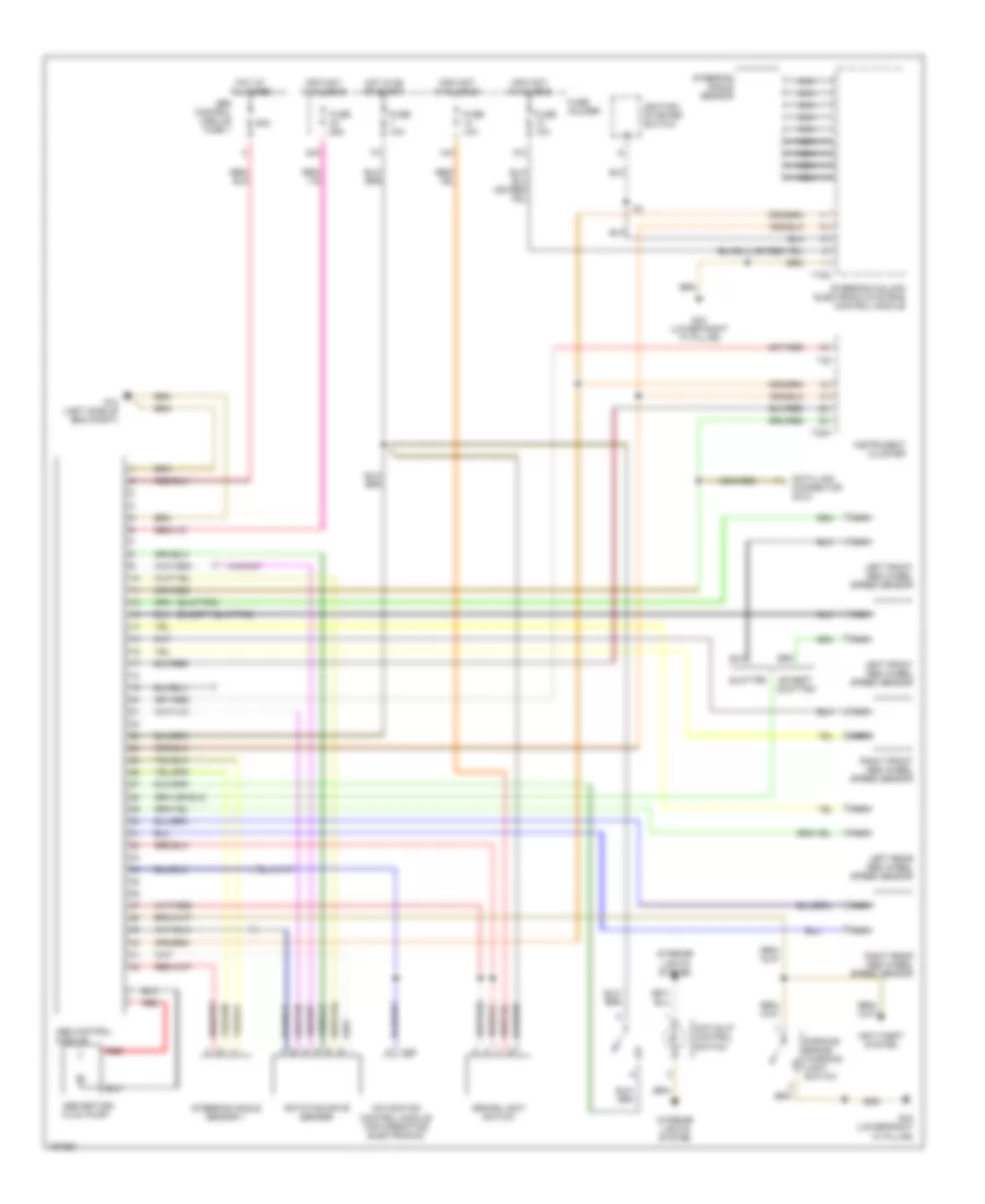
Anti-lock Brakes Wiring Diagram for Audi A4 2002
 https://portal-diagnostov.com/license.html
Automotive Electricians Portal FZCO
Automotive Electricians Portal FZCO
https://portal-diagnostov.com/license.html
https://portal-diagnostov.com/license.html
Automotive Electricians Portal FZCO
Automotive Electricians Portal FZCO
List of elements for Anti-lock Brakes Wiring Diagram for Audi A4 2002:
- (except quattro)
- (quattro)
- 13a
- 14a
- 42a
- 50a
- Abs control module
- Abs control module fuse 1
- Abs return flow pump
- Anti-slip control switch
- Anti-theft system
- Brake light switch
- Data link connector (dlc)
- Except quattro
- Fuse 10a
- Fuse 25a
- Fuse holder
- G12 (left side of eng compt)
- G43 (lower right "a" pillar)
- Hot at all times
- Hot in on or start
- Ignition/ starter switch
- Info not available
- Instrument cluster
- Interior lights system
- Left front abs wheel speed sensor
- Left rear abs wheel speed sensor
- Navigation control module for operating electronics
- Nca
- Parking brake warning light switch
- Quattro
- Red
- Right front abs wheel speed sensor
- Right rear abs wheel speed sensor
- Rotation rate sender
- Steering angle sensor
- Steering angle sensor 1
- Steering column electronic systems control module
- T16a
- T26
- T32
- T32a
 Čeština
 Dansk
Dansk Deutsch
 Ελληνικά
 English
 English
 Español
 Suomi
Suomi Français
 Français
 עברית
עברית Hrvatski
 Magyar
 Italiano
 日本語
日本語 Nederlands
 Polski
 Português
 Português
 Română
 Русский
 Slovenčina
 Slovenščina
 Svenska
 Türkçe
 中文 (中国)
 한국어
한국어
