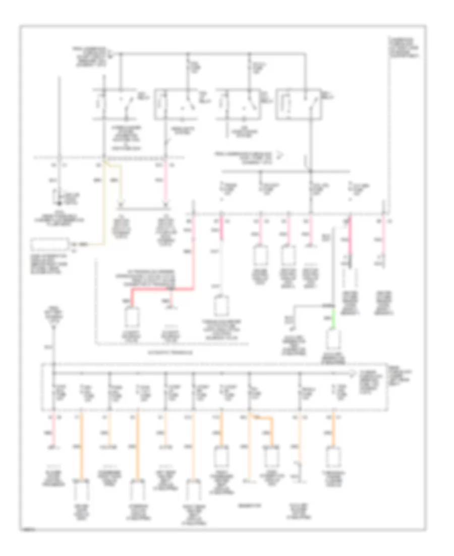
POWER DISTRIBUTION
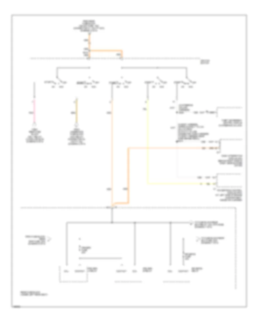
Power Distribution Wiring Diagram (1 of 8) for Cadillac DeVille DTS 2003
 https://portal-diagnostov.com/license.html
Automotive Electricians Portal FZCO
Automotive Electricians Portal FZCO
https://portal-diagnostov.com/license.html
https://portal-diagnostov.com/license.html
Automotive Electricians Portal FZCO
Automotive Electricians Portal FZCO
List of elements for Power Distribution Wiring Diagram (1 of 8) for Cadillac DeVille DTS 2003:
- (at right side of engine compartment) underhood fuse block
- (in dash harness approximately 31.5 cm (12.4 in) from 6 cavity gray in-line connector between dash harness & dash pad harness, near inflatable restraint i/p module, right side of dash) s209
- Abs fuse 50a
- Air pump fuse 50a
- Aldl fuse 10a
- Auxiliary generator
- Battery
- Coil
- Contact
- Cool fan 1 fuse 30a
- Cool fan 2 fuse 30a
- Coolfan 1 relay
- Coolfan 2 relay
- Coolfan s/p relay
- Data link connector (dlc) (partial)
- Drl fuse 15a
- Drl relay
- Electronic brake control module (ebcm)
- Evaporative emissions (evap) canister purge solenoid
- Fuel injector
- Fusible link
- Generator
- Hdlp hi bm relay
- Hdlp lo bm relay
- Horn fuse 15a
- Horn relay
- Ign 1 fuse 10a
- Injr 1 fuse 10a
- Injr 2 fuse 10a
- Instrument panel cluster (ipc)
- Ip fuse 10a
- Mass airflow (maf) sensor
- Nca
- Pcm batt fuse 10a
- Pcm/ign fuse 10a
- Pnk
- Powertrain control module (pcm)
- Red
- Secondary air injection (air) pump relay
- Secondary air injection (air) pump relay (if equipped)
- Secondary air injection (air) solenoid (if equipped)
- Start 1 relay
- Start circuit breaker 30a
- Starter solenoid
- Starting/charging system
- Theft deterrent control module
- To rear fuse block (diagram 2 of 8)
- To underhood fuse block (acc relay) (diagram 2 of 8)
- To underhood fuse block (ign 1 relay) (diagram 2 of 8)
- Valet switch
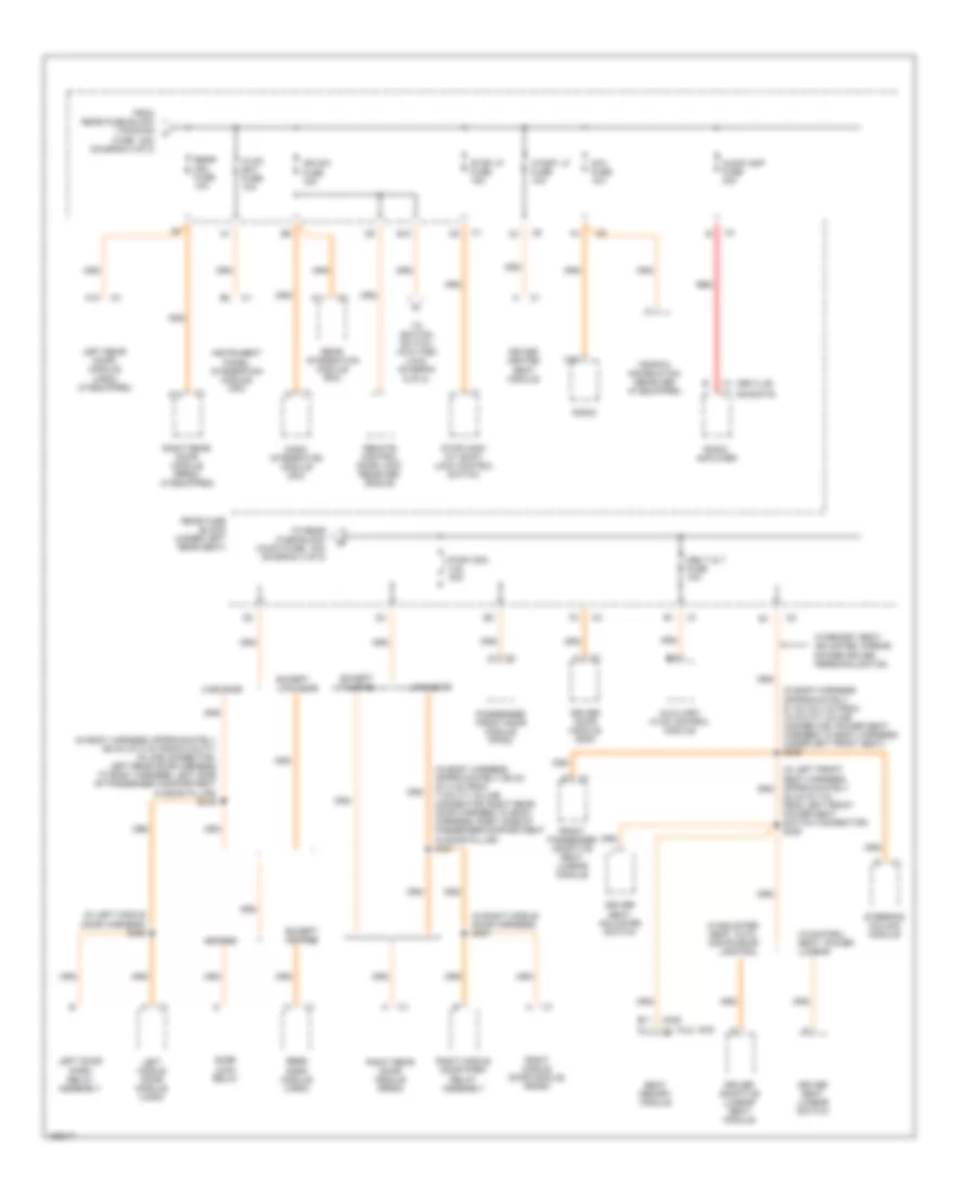
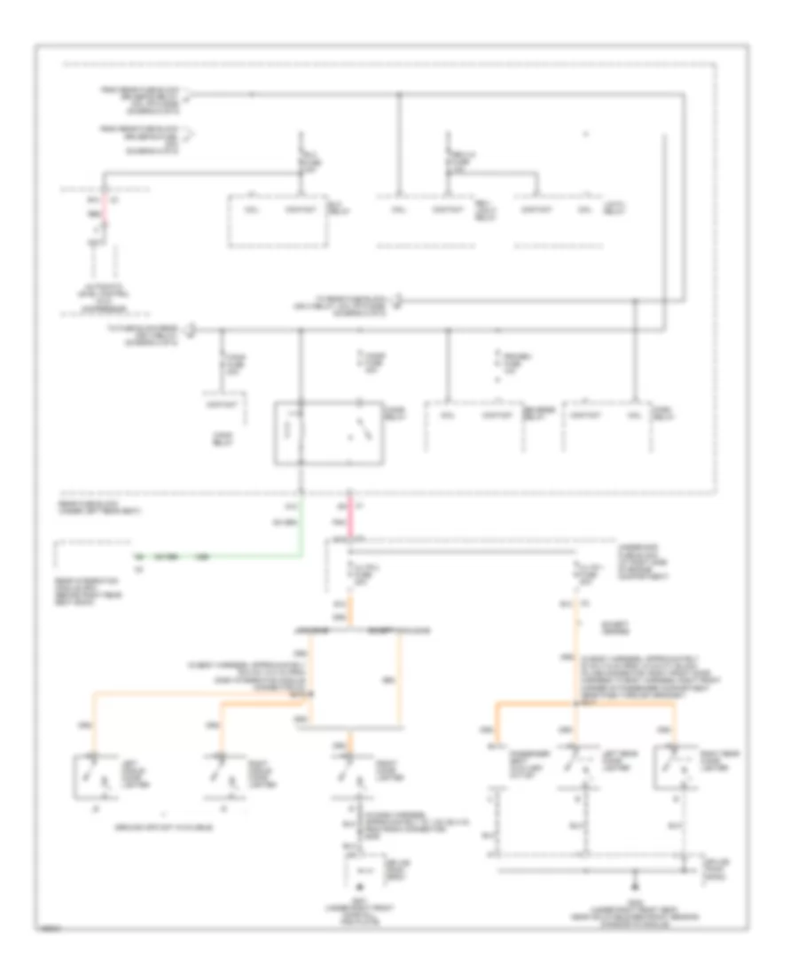
Power Distribution Wiring Diagram (2 of 8) for Cadillac DeVille DTS 2003
 https://portal-diagnostov.com/license.html
Automotive Electricians Portal FZCO
Automotive Electricians Portal FZCO
https://portal-diagnostov.com/license.html
https://portal-diagnostov.com/license.html
Automotive Electricians Portal FZCO
Automotive Electricians Portal FZCOList of elements for Power Distribution Wiring Diagram (2 of 8) for Cadillac DeVille DTS 2003:
- (in transaxle harness, approximately 33.5 cm (13.2 in) from 10 cavity in-line connector in transaxle) s113
- 1-2 shift solenoid valve
- 2-3 shift solenoid valve
- A/c clu relay
- A12
- Ac clu fuse 15a
- Acc relay
- Air conditioning system
- Automatic transaxle
- Auxiliary blower motor (if equipped)
- Auxiliary generator (if equipped)
- Auxiliary generator test connector (if equipped)
- B12
- Blower motor control processor
- Coil mdl fuse 20a
- Cr cont fuse 10a
- Cruise control module (ccm)
- D12
- Dash integration module (dim)
- Dash integration module (dim) (behind right side of dash, near blower motor)
- Dim fuse 10a
- Driver door module (ddm)
- Drv mdl fuse 10a
- E10
- F12
- Fog fuse 10a
- Fog lp relay
- From battery (diagram 1 of 8)
- From underhood fuse block (injr 1 fuse, 10a) (diagram 1 of 8)
- From underhood fuse block (start circuit breaker, 30a) (diagram 1 of 8)
- Front passenger heated seat module (if equipped)
- G104 (near windshield washer fluid reservoir filler neck)
- Generator
- Headlights system
- Heated oxygen sensor (ho2s) (bank 1, sensor 2)
- Heated oxygen sensor (ho2s) (bank 2, sensor 1)
- Htdst lr fuse 10a
- Htdst rf fuse 10a
- Htdst rr fuse 10a
- Hvac blo fuse 40a
- Ign 1 relay
- Ignition control module (icm) bank 1
- Ignition control module (icm) bank 2
- Left rear heated seat module (if equipped)
- Nca
- Oxy sen fuse 10a
- Pass mdl fuse 10a
- Passenger front door module (pfdm)
- Pnk
- Pwr t & t fuse 30a
- Rear fuse block (under left rear seat)
- Red
- Right rear heated seat module (if equipped)
- Rr blo fuse 10a
- S126
- Splice pack sp104
- Steering column module (if equipped)
- To ignition switch (cavity 7) (via splice s215) (diagram 5 of 8)
- To ignition switch (cavity 8) (diagram 6 of 8)
- To rear fuse block (rrdr mdl fuse, 10a) (diagram 3 of 8)
- Torque converter clutch pulse width modulation (tcc pwm) solenoid valve
- Trans fuse 10a
- Tsig/ haz fuse 15a
- Turn/signal hazard flasher module
- Underhood fuse block (at right side of engine compartment)
- Wiper/washer system (power for acc fuse (15a) & wsw fuse (30a)
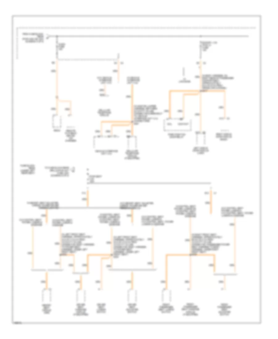
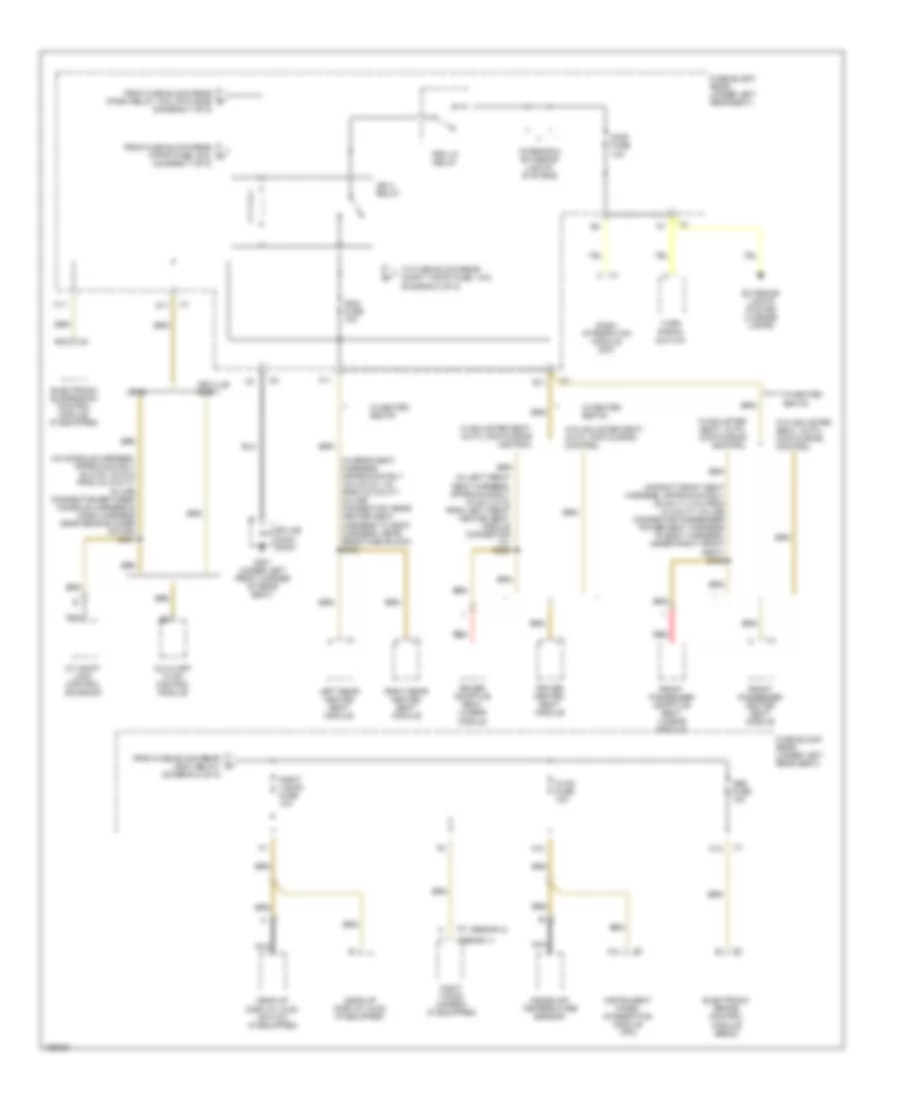
Power Distribution Wiring Diagram (3 of 8) for Cadillac DeVille DTS 2003
 https://portal-diagnostov.com/license.html
Automotive Electricians Portal FZCO
Automotive Electricians Portal FZCO
https://portal-diagnostov.com/license.html
https://portal-diagnostov.com/license.html
Automotive Electricians Portal FZCO
Automotive Electricians Portal FZCOList of elements for Power Distribution Wiring Diagram (3 of 8) for Cadillac DeVille DTS 2003:
- (ac9)
- (al2, am3)
- (deville)
- (dhs/dts)
- (in body harness approximately 69 cm (27.2 in) from 6 cavity in-line connector, left rear door harness to body harness, left side of passenger compartment in door pillar) s316
- (in body harness approximately 69 cm (27.2 in) from 7 cavity in-line connector, right rear door harness to body harness, right side of passenger compartment in door pillar) s321
- (in body harness approximately 87 cm (34.3 in) from 18 cavity in-line connector, power seat harness to body harness, under left front seat) s309
- (in left front seat harness, approximately 22 cm (8.7 in) from left front power seat switch connector) s328
- (in left middle door harness) s356
- (in right middle door harness) s357
- A11
- A12
- Audio amp fuse 30a
- Auxiliary hvac control module
- B11
- C15
- Dash integration module (dim)
- Door lock relay
- Driver adaptive lumbar seat module
- Driver door module (ddm)
- Driver heated seat module
- Driver seat adjuster switch
- Driver seat lumbar switch
- E10
- Except hearse
- Except limousine
- F11
- From rear fuse block (tsig/haz fuse, 15a) (diagram 2 of 8)
- Front passenger adaptive seat lumbar module
- Hearse
- Htdst lf fuse 10a
- Hvac bat fuse 10a
- Ign sw fuse 15a
- Instrument panel integration module (ipm)
- Left door park relay assembly
- Left middle door module (lmdm)
- Left rear door module (lrdm) (if equipped)
- Limousine
- Mem t & t fuse 10a
- Nav fuse 10a
- Passenger front door module (pfdm)
- Pwr wdo c.b. 30a
- Radio
- Radio amplifier
- Rear door module (lrdm)
- Rear fuse block (under left rear seat)
- Rear integration module (rim)
- Red
- Remote control door lock receiver (rcdlr)
- Right middle door module (rmdm)
- Right middle door park relay assembly
- Right rear door module (rrdm)
- Right rear door module (rrdm) (if equipped)
- Rrdr mdl fuse 10a
- Seat memory module
- Steering column module
- Stop lp fuse 15a
- Stoplamp/ a/t shift lock control switch
- To ignition switch (cavities 4 & 6) (diagram 6 of 8)
- To rear fuse block (audio fuse, 15a) (diagram 4 of 8)
- Traffic information receiver (if equipped)
- W/adjuster seat, auto, contouring control
- W/control seat, power lumbar
- W/memory seat adjuster, mirror, power driver personalization
Power Distribution Wiring Diagram (4 of 8) for Cadillac DeVille DTS 2003
 https://portal-diagnostov.com/license.html
Automotive Electricians Portal FZCO
Automotive Electricians Portal FZCO
https://portal-diagnostov.com/license.html
https://portal-diagnostov.com/license.html
Automotive Electricians Portal FZCO
Automotive Electricians Portal FZCOList of elements for Power Distribution Wiring Diagram (4 of 8) for Cadillac DeVille DTS 2003:
- (in body harness, on right rear of passenger compartment, approximately 22.5 cm (9 in) from cross car channel) s317
- (in onstar jumper harness, between 30 cavity in-line connector & breakout to vehicle interface unit (viu) connectors) s361
- 18 cavity in-line connector, body harness to power seat harness, under left front seat) s324
- 18 cavity in-line connector, passenger power seat harness to body harness, under right front seat) s330
- A12
- Audio fuse 15a
- Cellular telephone module
- Cellular telephone module (if equipped)
- Coil
- Contact
- Driver seat adjuster switch
- Driver seat lumbar switch
- Driver seat massage module (if equipped)
- E12
- E16
- Export ltg/ pwr lk fuse 15a
- F12
- From fuse block- rear (pwr wdo cb, 30a) (diagram 3 of 8)
- Front passenger seat adjuster switch
- Front passenger seat lumbar switch
- Front passenger seat massage module (if equipped)
- Fuse block- rear (under left rear seat)
- Left middle door module (lmdm)
- Memory seat module (msm)
- Park position door relay
- Pwr seat c.b. 30a
- Radio
- Remote playback device- (cd changer)
- Right middle door module (rmdm)
- To fuse block-rear (rrlum/pwr ant fuse, 20a) (diagram 5 of 8)
- Vehicle interface unit (viu)
- W/ limousine
- W/control seat power lumbar or w/control seat power lumbar & massage
- W/control seat power lumbar or w/control seat, power lumbar & massage
- W/control seat, power lumbar & massage
- W/memory seat adjuster, mirror, power driver personalization
- W/o control seat power lumbar & w/o control seat, power lumbar & massage
- W/o control seat, power lumbar & massage
- W/o memory seat adjuster, mirror, power driver personalization
- W/o vehicle interface unit (viu)
- W/vehicle interface unit (viu)
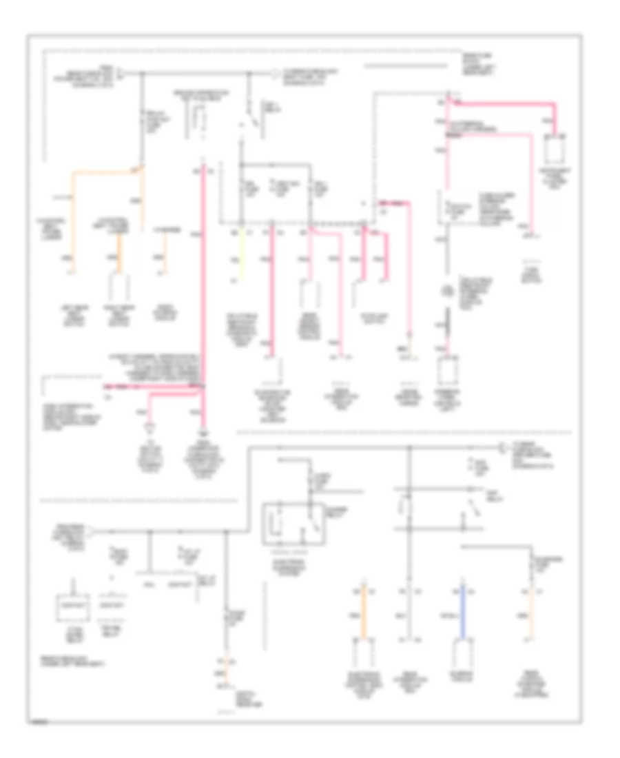
Power Distribution Wiring Diagram (5 of 8) for Cadillac DeVille DTS 2003
 https://portal-diagnostov.com/license.html
Automotive Electricians Portal FZCO
Automotive Electricians Portal FZCO
https://portal-diagnostov.com/license.html
https://portal-diagnostov.com/license.html
Automotive Electricians Portal FZCO
Automotive Electricians Portal FZCOList of elements for Power Distribution Wiring Diagram (5 of 8) for Cadillac DeVille DTS 2003:
- (in body harness, approximately 53.5 cm (21.1 in) from 40 cavity in-line connector, body harness to dash harness, under right side of dash) s215
- Body fuse 15a
- Coil
- Contact
- Cvrtd fuse 10a
- Damper relay
- Dash integration module (dim) (behind right side of dash, near blower motor)
- Digital radio receiver
- Electronic suspension control (esc) module (dts)
- Electronic suspension system
- Evaporative emissions (evap) canister vent solenoid
- F/tnk dr rel relay
- F2 c2
- From rear fuse block (power seat c.b., 30a) (diagram 4 of 8)
- From rear fuse block i (ign 1 relay) (diagram 5 of 8)
- From underhood fuse block (connector c2 cavity e10) (diagram 2 of 8)
- Fuse holder- steering column (near base of steering column)
- Ground information not available
- Ign 1 fuse 10a
- Ign 1 relay
- Inflatable restraint sensing & diagnostic module (sdm)
- Inflatable restraint steering wheel module coil
- Inside rearview mirror
- Instrument panel cluster (ipc)
- Int lp fuse 10a
- Int lp relay
- Left rear seat lumbar switch
- Nca
- Pnk
- Pnk (in steering column harness) s222
- Radio antenna module
- Rap fuse 30a
- Rap relay
- Rear fuse block (under left rear seat)
- Rear integration module (rim)
- Rear object sensor control module
- Rear window sunshade module (if equipped)
- Right rear seat lumbar switch
- Rrlum/ pwr ant fuse 20a
- S-dar fuse 5a
- Sir fuse 10a
- Steering wheel controls (left)
- Stoplamp switch
- Sunroof module
- Sunshade fuse 10a
- Switch fuse 2a
- To ignition switch (cavity 7) (diagram 6 of 8)
- To rear fuse block (body fuse, 15a) (diagram 5 of 8)
- To rear fuse block (prk brk fuse, 20a) (diagram 6 of 8)
- Trk rel relay
- Turn signal switch
- Vent sol fuse 10a
- W/control seat, power lumbar
- W/hearse
Power Distribution Wiring Diagram (6 of 8) for Cadillac DeVille DTS 2003
 https://portal-diagnostov.com/license.html
Automotive Electricians Portal FZCO
Automotive Electricians Portal FZCO
https://portal-diagnostov.com/license.html
https://portal-diagnostov.com/license.html
Automotive Electricians Portal FZCO
Automotive Electricians Portal FZCOList of elements for Power Distribution Wiring Diagram (6 of 8) for Cadillac DeVille DTS 2003:
- (in body harness, approximately 73.2 cm (28.8 in) from 40 cavity in-line connector, dash harness to body harness near park brake pedal) s213
- (in steering column harness) s220
- A11
- Acc
- Coil
- Contact
- Dash integration module (dim) (behind right side of dash, near blower motor)
- From fuse block- rear (rap fuse, 30a) (diagram 5 of 8)
- From rear fuse block (ign 1 relay) (via splice s215) (diagram 5 of 8)
- From rear fuse block (ign sw fuse, 15a) (connector c1, cavity e10) (diagram 3 of 8)
- From underhood fuse block (acc relay) (connector c2, cavity d2) (diagram 2 of 8)
- Ignition switch
- Nca
- Off
- Pnk
- Powertrain control module (pcm) (at left side of engine compartment, inside air cleaner)
- Prk brk a relay
- Prk brk b relay
- Prk/brk fuse 20a
- Rear fuse block (under left rear seat)
- Rr defog fuse 40a
- Rr defog relay
- S218
- Start
- Theft deterrent control module (in steering column)
- To fuse block-rear (elc fuse, 30a) (diagram 7 of 8)
- To fuse block-rear (elc relay, coil rtn side) (diagram 7 of 8)
Power Distribution Wiring Diagram (7 of 8) for Cadillac DeVille DTS 2003
 https://portal-diagnostov.com/license.html
Automotive Electricians Portal FZCO
Automotive Electricians Portal FZCO
https://portal-diagnostov.com/license.html
https://portal-diagnostov.com/license.html
Automotive Electricians Portal FZCO
Automotive Electricians Portal FZCOList of elements for Power Distribution Wiring Diagram (7 of 8) for Cadillac DeVille DTS 2003:
- (ground info not available)
- (in body harness, approximately 35.5 cm (14.0 in) from dash integration module connector c3) s216
- (in dash harness, approximately 72.1 cm (28.4 in) from radio connector) s206
- Automatic level control (alc) compressor
- B10
- B12
- C/ltr 1 fuse 20a
- C/ltr 2 fuse 20a
- Cigar fuse 40a
- Cigar relay
- Coil
- Contact
- D10
- D12
- E12
- Elc fuse 30a
- Elc relay
- Except hearse
- Except limousine
- F/pmp fuse 20a
- F/pmp relay
- From rear fuse block (rr defog fuse, l 40a) (diagram 6 of 8)
- From rear fuse block (rr defog relay, k coil rtn side) (diagram 6 of 8)
- Front cigar lighter
- G201 (under right front door sill trim plate)
- G302 (under right front seat, near inflatable restraint sensing diagnostic module)
- Left middle cigar lighter
- Left rear cigar lighter
- Limousine
- Lk/cyl relay
- Nca
- Park relay
- Passenger seat auxiliary outlet
- Pnk
- Prk/rev fuse 10a
- Rear fuse block (under left rear seat)
- Rear integration module (rim) (behind right rear seat back)
- Red
- Rev/ lkout relay
- Rev/lk fuse 10a
- Reverse relay
- Right middle cigar lighter
- Right rear cigar lighter
- Splice pack sp201
- Splice pack sp302
- To fuse block-rear (ign 3 relay) (diagram 8 of 8)
- To rear fuse block (ign 3 relay, coil rtn side) (diagram 8 of 8)
- Underhood fuse block (at right side of engine compartment)
Power Distribution Wiring Diagram (8 of 8) for Cadillac DeVille DTS 2003
 https://portal-diagnostov.com/license.html
Automotive Electricians Portal FZCO
Automotive Electricians Portal FZCO
https://portal-diagnostov.com/license.html
https://portal-diagnostov.com/license.html
Automotive Electricians Portal FZCO
Automotive Electricians Portal FZCOList of elements for Power Distribution Wiring Diagram (8 of 8) for Cadillac DeVille DTS 2003:
- (design 1)
- (design 2)
- (diagram 7 of 8)
- (in console harness, approximately 50.5 cm (19.9 in) from 30 cavity in-line connector between console harness & dash harness near rear blower motor) s301
- (in left front seat harness, approximately 19 cm (7.5 in) from left front heated seat module connector c1) s329
- (in rear seat harness, approximately 15.5 cm (6.1 in) from 30 cavity in-line connector, rear heated seat harness to body harness, near rear fuse block) s333
- (in right front seat harness, approximately 29 cm (11.4 in) from 18 cavity in-line connector passenger power seat harness to body harness, under right front seat) s332
- A/t shift lock control solenoid
- A10
- A11
- Abs fuse 10a
- Auxiliary hvac control module
- B12
- C1 h
- C11
- C12
- D11
- Dash integration module (dim)
- Deville/ dhs
- Dimr fuse 10a
- Driver adaptive seat lumbar module
- Driver heated seat module
- Dts
- E11
- Electronic brake control module (ebcm)
- Electronic suspension control module (if equipped)
- Exterior lights system (license lamps)
- F11
- From fuse block-rear (f/pmp fuse, 20a) n
- From fuse block-rear (ign 3 relay) (diagram 8 of 8)
- From fuse block-rear (park relay, coil rtn side) (diagram 7 of 8)
- Front passenger adaptive seat lumbar module
- Front passenger heated seat module
- Fuse block- rear (under left rear seat)
- G301 (under left front corner of rear seat)
- Head-up display (hud) (if equipped)
- Head-up display (hud) switch (if equipped)
- Hvac fuse 10a
- Ign 3 relay
- Ign3 fuse 10a
- Inside air temperature sensor
- Instrument panel integration module (ipm)
- Interior & exterior lights systems
- Left rear heated seat module
- Nca
- Night vision camera (if equipped)
- Night vision fuse 10a
- Prk lp relay
- Red
- Right rear heated seat module
- Splice pack sp301
- To fuse block-rear (night vision fuse, 10a) (diagram 8 of 8)
- Turn signal switch
- W/adjuster seat, auto, contouring control
- W/heated seats
- W/o adjuster seat, auto, contouring control

 Čeština
 Dansk
Dansk Deutsch
 Ελληνικά
 English
 English
 Español
 Suomi
Suomi Français
 Français
 עברית
עברית Hrvatski
 Magyar
 Italiano
 日本語
日本語 Nederlands
 Polski
 Português
 Português
 Română
 Русский
 Slovenčina
 Slovenščina
 Svenska
 Türkçe
 中文 (中国)
