AIR CONDITIONING
Automatic A/C Wiring Diagram (1 of 2) for Honda Accord EX 2001
 https://portal-diagnostov.com/license.html
Automotive Electricians Portal FZCO
Automotive Electricians Portal FZCO
https://portal-diagnostov.com/license.html
https://portal-diagnostov.com/license.html
Automotive Electricians Portal FZCO
Automotive Electricians Portal FZCO
List of elements for Automatic A/C Wiring Diagram (1 of 2) for Honda Accord EX 2001:
- A/c on output
- A/c pressure switch (behind right side of front bumper)
- A10
- A11
- A12
- A13
- A14
- A15
- A16
- A17
- A18
- A19
- A20
- Air mix control motor (below dash, on right side of heater unit)
- Air mix cool
- Air mix hot
- Air mix pot
- Amd-p
- Blower feedback
- Blower rly ctrl
- Climate control unit
- Driver's underdash fuse/relay box (behind left side of dash, behind left fuse box cover)
- Ect input
- Evap sen in
- Evaporator temperature sensor (behind glove box, in evaporator unit)
- Fresh ctrl
- Frs
- Fuse 13-pass
- Fuse 15a
- Fuse 7.5a
- G200 (left kick panel)
- Ground
- High
- Hot at all times
- Hot in on
- Hot in on or start
- Ig2
- Ign on input
- Illumination +
- Illumination -
- In-car temp in
- In-car temperature sensor (in left lower dash panel, right of steering column)
- Interior lights system
- J12
- Low
- M-cool
- M-def
- M-hot
- M-vent
- Mode 1
- Mode 2
- Mode 3
- Mode 4
- Mode control motor (on left side of heater unit)
- Mode-def
- Mode-vent
- O13
- O14
- Out air temp in
- Outside air temperature sensor (below center of front bumper)
- Passenger's fuse/relay box (behind right side of dash)
- Passenger's underdash fuse/relay box (behind right side of dash, behind right fuse box cover)
- Pwr tran ctrl
- Rear def on out
- Rec
- Recirc ctrl
- Recirculation control motor (behind glove box, on blower unit)
- Red
- Ref voltage
- S-com
- S5v
- Sensor gnd
- Sunlight sen in
- Sunlight sensor (on center front of dash)
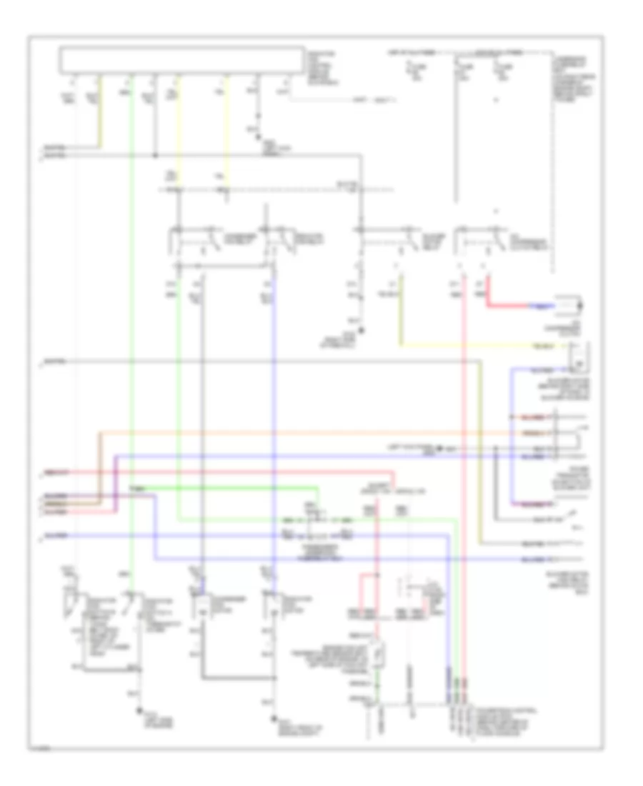
Automatic A/C Wiring Diagram (2 of 2) for Honda Accord EX 2001
 https://portal-diagnostov.com/license.html
Automotive Electricians Portal FZCO
Automotive Electricians Portal FZCO
https://portal-diagnostov.com/license.html
https://portal-diagnostov.com/license.html
Automotive Electricians Portal FZCO
Automotive Electricians Portal FZCOList of elements for Automatic A/C Wiring Diagram (2 of 2) for Honda Accord EX 2001:
- (left kick panel) g200
- (on bottom of blower unit)
- A/c compressor clutch
- A/c compressor clutch relay
- A/c on in
- A17
- A20
- A27
- Blower motor (behind right side of dash, in blower housing)
- Blower motor high relay (behind glove box)
- Blower motor relay
- C18
- C26
- Condenser fan motor
- Condenser fan relay
- D10
- D11
- D12
- D14
- D16
- Ect
- Engine coolant temperature sensor (ect) (on rear of engine, on left side of coolant passage)
- Except 2000-01 (v6) 2000-01 (v6)
- Fan cntrl
- Fuse 20a
- Fuse 40a
- G101 (right front of engine compt)
- G112 (left side of engine)
- G123 (right side of firewall)
- G200 (left kick panel)
- H17
- Hot at all times
- I17
- J/c- c108 (right side of dash)
- K14
- Nca
- Passenger's underdash fuse/relay box
- Power transistor
- Powertrain control module (pcm) (behind center of dash, forward of floor console)
- Radiator fan control module (behind glove box)
- Radiator fan motor
- Radiator fan relay
- Radiator fan switch a (on thermostat cover)
- Radiator fan switch b (behind
- Red
- Rel cntrl
- Sens grd
- Timing belt back cover, on front of left cylinder head)
- Underhood fuse/relay box (on right rear corner of engine compt, behind strut tower)
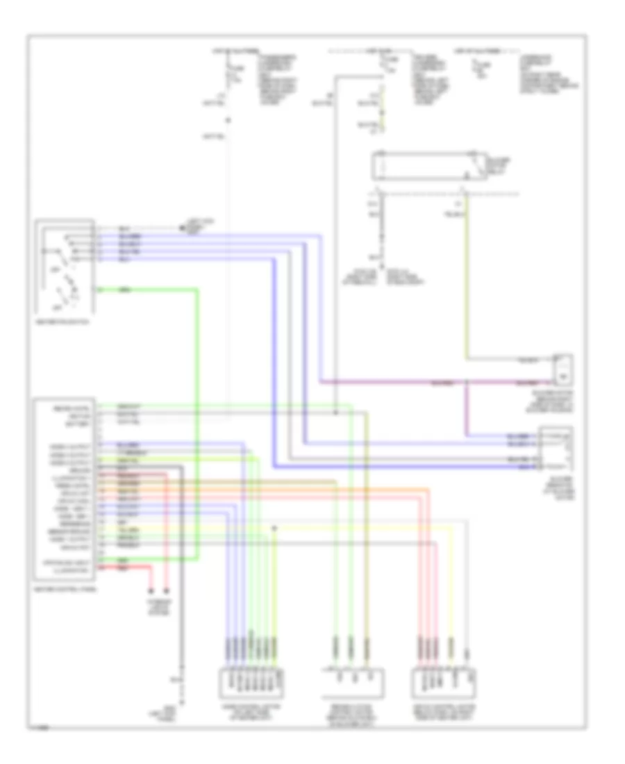
Heater Wiring Diagram for Honda Accord EX 2001
 https://portal-diagnostov.com/license.html
Automotive Electricians Portal FZCO
Automotive Electricians Portal FZCO
https://portal-diagnostov.com/license.html
https://portal-diagnostov.com/license.html
Automotive Electricians Portal FZCO
Automotive Electricians Portal FZCOList of elements for Heater Wiring Diagram for Honda Accord EX 2001:
- (at blower motor)
- (left kick panel) g200
- Air mix control motor (below dash, on right side of heater unit)
- Air mix cool
- Air mix hot
- Air mix pot
- Amd-p
- Battery
- Blower motor (behind right side of dash, in blower housing)
- Blower motor relay
- Blower resistor
- D14
- Driver's underdash fuse/relay box (behind left side of dash, behind left fuse box cover)
- Fresh cntrl
- Frs
- Fuse 40a
- Fuse 7.5a
- G103 (l4) (right side of eng compt)
- G123 (v6) (right side of firewall)
- G200 (left kick panel)
- Ground
- Heater control panel
- Heater fan switch
- Hot at all times
- Hot in on
- Htr fan sw input
- Ig2
- Ignition
- Illumination +
- Illumination -
- Interior lights system
- J12
- M-cool
- M-def
- M-hot
- M-vent
- Mode - def +
- Mode - vent +
- Mode 1
- Mode 1 output
- Mode 2
- Mode 2 output
- Mode 3
- Mode 3 output
- Mode 4
- Mode 4 output
- Mode control motor (on left side of heater unit)
- O13
- Off
- Passenger's underdash fuse/relay box (behind right side of dash, behind right fuse box cover)
- Rec
- Recirc cntrl
- Recirculation control motor (behind glove box on blower unit)
- Red
- Reference
- S-com
- S5v
- Sensor ground
- Underhood fuse/relay box (on right rear corner of engine compartment behind strut tower)
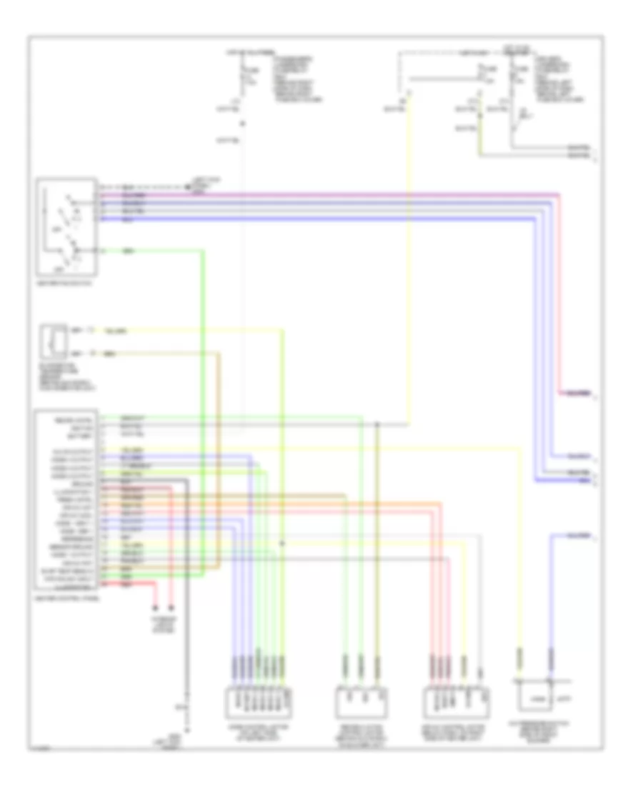
Manual A/C Wiring Diagram (1 of 2) for Honda Accord EX 2001
 https://portal-diagnostov.com/license.html
Automotive Electricians Portal FZCO
Automotive Electricians Portal FZCO
https://portal-diagnostov.com/license.html
https://portal-diagnostov.com/license.html
Automotive Electricians Portal FZCO
Automotive Electricians Portal FZCOList of elements for Manual A/C Wiring Diagram (1 of 2) for Honda Accord EX 2001:
- (left kick panel) g200
- A/c on output
- A/c pressure switch (behind right side of front bumper)
- Air mix control motor (below dash, on right side of heater unit)
- Air mix cool
- Air mix hot
- Air mix pot
- Amd-p
- Battery
- Driver's underdash fuse/relay box (behind left side of dash, behind left fuse box cover)
- Evap temp sens in
- Evaporator temperature sensor (behind glove box, in evaporator unit)
- Fresh cntrl
- Frs
- Fuse 15a
- Fuse 7.5a
- G200 (left kick panel)
- Ground
- Heater control panel
- Heater fan switch
- High
- Hot at all times
- Hot in on
- Hot in on or start
- Htr fan sw input
- Ig2
- Ignition
- Illumination +
- Illumination -
- Interior lights system
- J12
- Low
- M-cool
- M-def
- M-hot
- M-vent
- Mode - def +
- Mode - vent +
- Mode 1
- Mode 1 output
- Mode 2
- Mode 2 output
- Mode 3
- Mode 3 output
- Mode 4
- Mode 4 output
- Mode control motor (on left side of heater unit)
- O13
- O14
- Off
- Passenger's underdash fuse/relay box (behind right side of dash, behind right fuse box cover)
- Rec
- Recirc cntrl
- Recirculation control motor (behind glove box, on blower unit)
- Red
- Reference
- S-com
- S5v
- Sensor ground
- V6 only
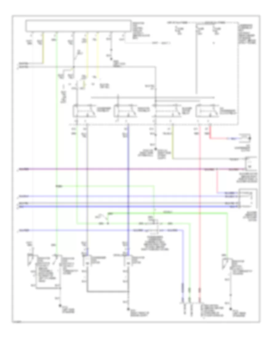
Manual A/C Wiring Diagram (2 of 2) for Honda Accord EX 2001
 https://portal-diagnostov.com/license.html
Automotive Electricians Portal FZCO
Automotive Electricians Portal FZCO
https://portal-diagnostov.com/license.html
https://portal-diagnostov.com/license.html
Automotive Electricians Portal FZCO
Automotive Electricians Portal FZCOList of elements for Manual A/C Wiring Diagram (2 of 2) for Honda Accord EX 2001:
- (behind timing belt back cover, on front of left cylinder head)
- A/c compressor clutch
- A/c compressor clutch relay
- A/c on in
- A17
- A20
- A27
- Blower motor (behind right side of dash, in blower housing)
- Blower motor relay
- Blower resistor (at blower motor)
- Condenser fan motor
- Condenser fan relay
- D10
- D11
- D12
- D14
- D16
- Ecm or pcm (behind center of dash, forward of floor console)
- Fan cntrl
- Fuse 20a
- Fuse 40a
- G101 (right front of engine compt)
- G103 (l4) (right side of eng compt)
- G112 (left side of engine)
- G114 (left rear of engine)
- G123 (v6) (right side of firewall)
- G200 (left kick panel)
- H17
- Hot at all times
- I17
- K14
- L4 only
- Nca
- Passenger's underdash fuse/relay box (behind right side of dash, behind right fuse box cover)
- Radiator fan control module (v6 only) (behind glove box)
- Radiator fan motor
- Radiator fan relay
- Radiator fan switch (l4 only) (on thermostat housing)
- Radiator fan switch a (v6 only) (on thermostat cover)
- Radiator fan switch b (v6 only)
- Red
- Rel cntrl
- Underhood fuse/relay box (on right rear corner of engine compt, behind strut tower)
- V6 only

 Čeština
 Dansk
Dansk Deutsch
 Ελληνικά
 English
 English
 Español
 Suomi
Suomi Français
 Français
 עברית
עברית Hrvatski
 Magyar
 Italiano
 日本語
日本語 Nederlands
 Polski
 Português
 Português
 Română
 Русский
 Slovenčina
 Slovenščina
 Svenska
 Türkçe
 中文 (中国)
