ANTI-THEFT
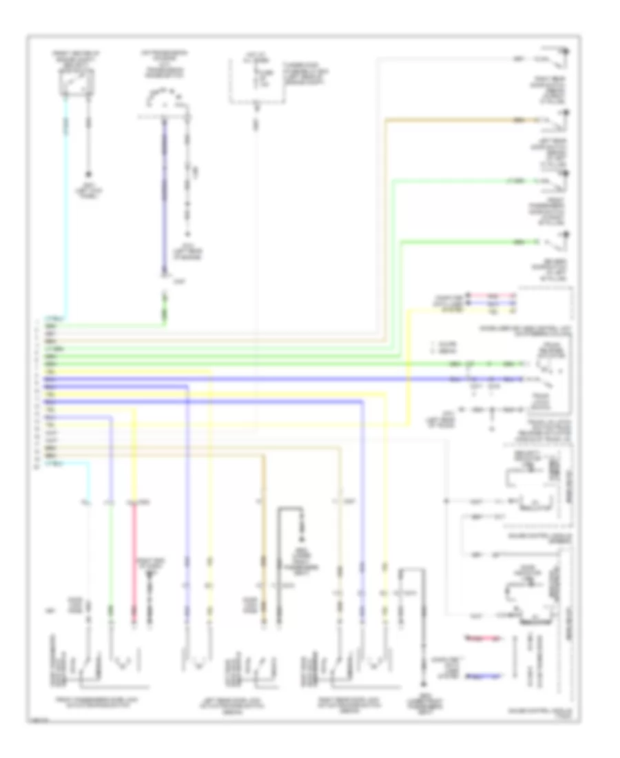
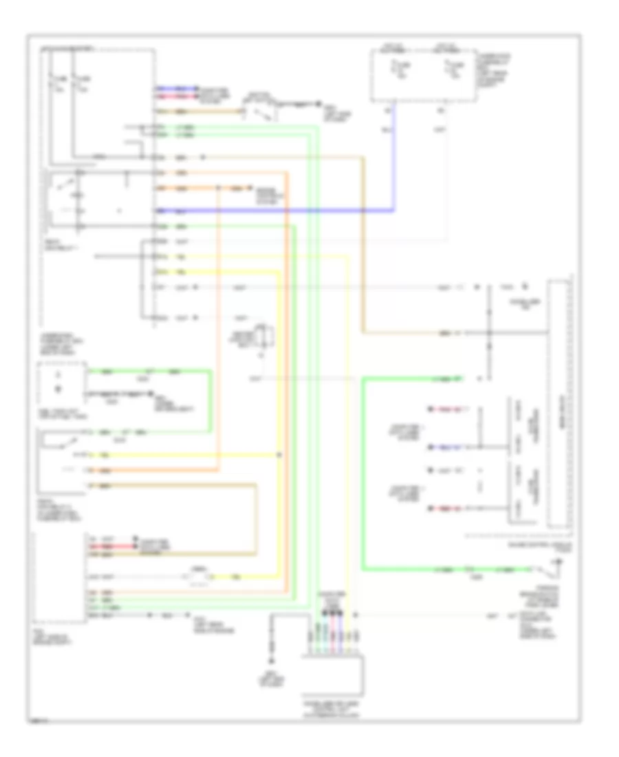
Forced Entry Wiring Diagram, Except Hybrid (1 of 2) for Honda Civic LX 2013
 https://portal-diagnostov.com/license.html
Automotive Electricians Portal FZCO
Automotive Electricians Portal FZCO
https://portal-diagnostov.com/license.html
https://portal-diagnostov.com/license.html
Automotive Electricians Portal FZCO
Automotive Electricians Portal FZCO
List of elements for Forced Entry Wiring Diagram, Except Hybrid (1 of 2) for Honda Civic LX 2013:
- (left side of dash) g502
- (right end of dash) g504
- (under front passenger's seat) g602
- B11
- B15
- B18
- B22
- B29
- B32
- B33
- B34
- B40
- C19
- C202
- C210
- C27
- C37
- Computer data lines system
- D/l dr unlock relay
- D/l lock relay
- D/l unlock relay
- D23
- D28
- D29
- Driver's door lock actuator/knob switch/key cylinder switch
- Driver's door lock knob switch
- Ex-l
- Except ex-l
- Exterior lights system
- Front passenger's power window switch
- Fuse 10a
- Fuse 15a
- Fuse 20a
- Fuse 7.5a
- G502 (left side of dash)
- G503 (under left side of dash)
- Headlights system
- Horns system
- Hot at all times
- Hot in on or start
- Ignition key switch
- J/c c010
- Key cylinder switch driver's door
- Knob lock door key
- Lock
- Micu
- N10
- N12
- Neutral
- P11
- P18
- P20
- Pnk
- Power window master switch
- Q10
- Sedan
- Trunk release actuator relay
- Under-dash fuse/relay box (under left end of dash)
- Unlock
- W10
- X10
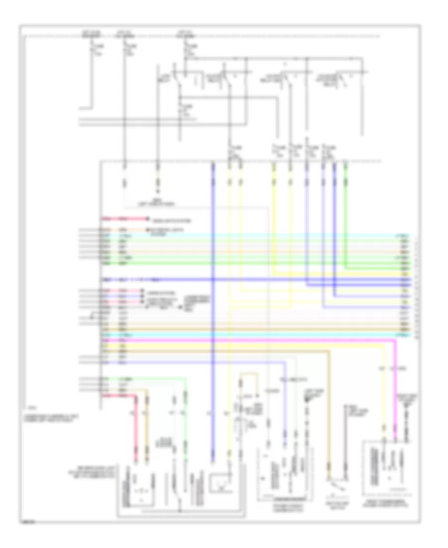
Forced Entry Wiring Diagram, Except Hybrid (2 of 2) for Honda Civic LX 2013
 https://portal-diagnostov.com/license.html
Automotive Electricians Portal FZCO
Automotive Electricians Portal FZCO
https://portal-diagnostov.com/license.html
https://portal-diagnostov.com/license.html
Automotive Electricians Portal FZCO
Automotive Electricians Portal FZCOList of elements for Forced Entry Wiring Diagram, Except Hybrid (2 of 2) for Honda Civic LX 2013:
- (front center of engine compt) security hood switch
- (on transmission housing) (a/t) transmission range switch
- (right end of dash) g504
- 5v regulator
- B-can h
- B-can l
- B-can transceiver
- Blinking circuit
- C202
- C207
- C212
- C213
- C217
- C219
- C405
- C407
- Computer data lines system
- Coupe
- Door indicator (led)
- Driver's door switch (in left "b" pillar)
- Front passenger's door lock actuator/knob switch
- Front passenger's door switch (in right "b" pillar)
- Fuse 10a
- G101 (left rear of engine)
- G401 (left kick panel)
- G602 (under front passenger's seat)
- G701 (left rear of trunk)
- Gauge control module (speedo)
- Gauge control module (tach)
- Hot at all times
- Immobilizer keyless control unit (on steering column)
- Indicator drive circuit
- Key
- Knob switch door lock front passenger's
- Knob switch door lock left rear
- Knob switch door lock right rear
- Left rear door lock actuator/knob switch (sedan)
- Left rear door switch (sedan) (in left "c" pillar)
- Lock
- Main circuit
- Pnk
- Right rear door lock actuator/knob switch (sedan)
- Right rear door switch (sedan) (in right "c" pillar)
- Security indicator (led)
- Sedan
- Trunk latch switch
- Trunk lid latch switch/trunk release actuator (middle of trunk lid)
- Trunk release actuator
- Under-hood fuse/relay box (left rear of engine compt)
- Unlock
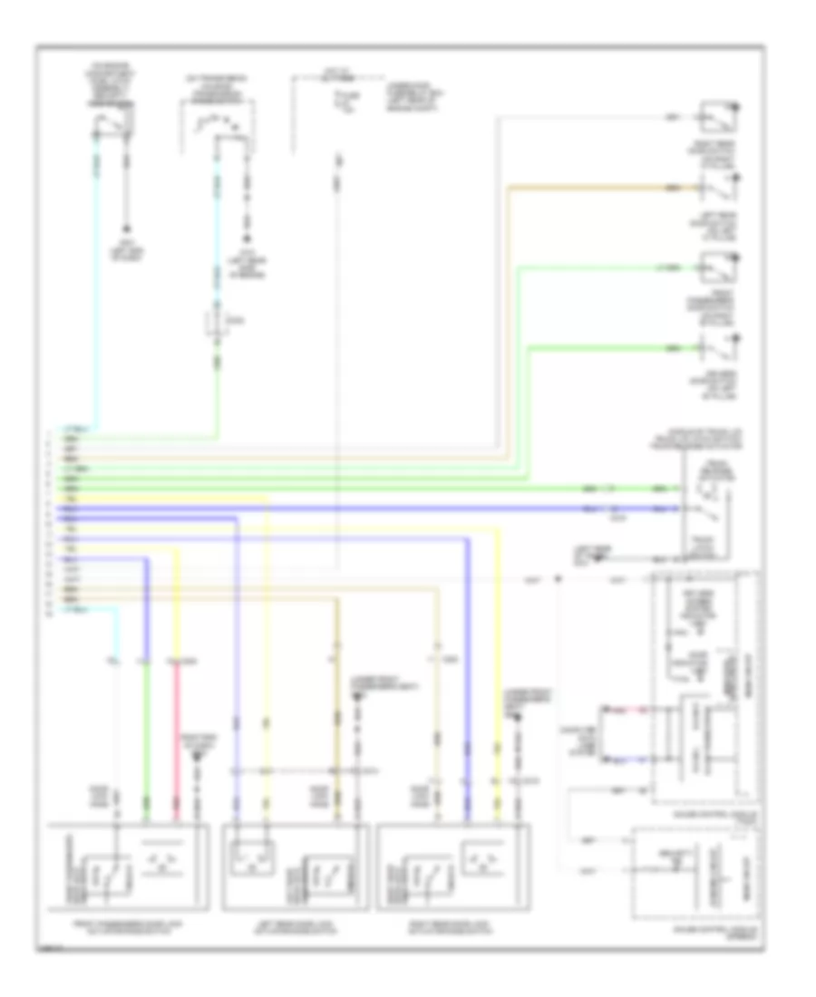
Forced Entry Wiring Diagram, Hybrid (1 of 2) for Honda Civic LX 2013
 https://portal-diagnostov.com/license.html
Automotive Electricians Portal FZCO
Automotive Electricians Portal FZCO
https://portal-diagnostov.com/license.html
https://portal-diagnostov.com/license.html
Automotive Electricians Portal FZCO
Automotive Electricians Portal FZCOList of elements for Forced Entry Wiring Diagram, Hybrid (1 of 2) for Honda Civic LX 2013:
- (left side of dash) g502
- (right end of dash) g504
- (under front passenger's seat) g602
- B11
- B15
- B18
- B22
- B29
- B32
- B33
- B34
- B40
- C18
- C19
- C202
- C203
- C212
- C27
- C37
- Computer data lines system
- Control block
- D23
- D28
- Door lock switch front passenger's
- Driver's door lock actuator/knob switch/ key cylinder switch
- Driver's door lock knob switch
- Exterior lights system
- Front passenger's power window switch
- Fuse 10a
- Fuse 15a
- Fuse 20a
- Fuse 7.5a
- G502 (left side of dash)
- G503 (left side of dash)
- Headlights system
- Horns system
- Hot at all times
- Hot in on or start
- Ignition key switch
- J/c c008
- Key cylinder switch driver's door
- Knob lock door key
- Lock
- Lock relay
- Lock switch driver's door
- Micu
- N10
- N12
- Neutral
- P11
- P20
- Pnk
- Power window master switch
- Tailgate actuator relay
- U10
- Under-dash fuse/relay box (under left end of dash)
- Unlock
- Unlock relay
- Unlock relay (dr)
- V10
Forced Entry Wiring Diagram, Hybrid (2 of 2) for Honda Civic LX 2013
 https://portal-diagnostov.com/license.html
Automotive Electricians Portal FZCO
Automotive Electricians Portal FZCO
https://portal-diagnostov.com/license.html
https://portal-diagnostov.com/license.html
Automotive Electricians Portal FZCO
Automotive Electricians Portal FZCOList of elements for Forced Entry Wiring Diagram, Hybrid (2 of 2) for Honda Civic LX 2013:
- (left rear of trunk) g701
- (middle of trunk lid) trunk lid latch switch/ trunk release actuator
- (on engine compartment hood latch assembly) security hood switch
- (on transmission housing) transmission range switch
- (right end of dash) g504
- (under front passenger's seat) g602
- B-can h
- B-can l
- B-can transceiver
- Blinking circuit
- C202
- C208
- C214
- C215
- C219
- C302
- Computer data lines system
- Door indicator (led)
- Driver's door switch (on left "b" pillar)
- Front passenger's door lock actuator/knob switch
- Front passenger's door switch (on right "b" pillar)
- Fuse 10a
- G101 (left rear side of engine)
- G401 (left end of dash)
- Gauge control module (speedo)
- Gauge control module (tach)
- Hot at all times
- Indicator drive circuit
- Keyless access system indicator (led)
- Knob switch door lock front passenger's
- Knob switch door lock left rear
- Knob switch door lock right rear
- Left rear door lock actuator/knob switch
- Left rear door switch (on left "c" pillar)
- Lock
- Main circuit
- Pnk
- Right rear door lock actuator/knob switch
- Right rear door switch (on right "c" pillar)
- Security ind
- Trunk latch switch
- Trunk release actuator
- Under-hood fuse/relay box (left rear of engine compt)
- Unlock
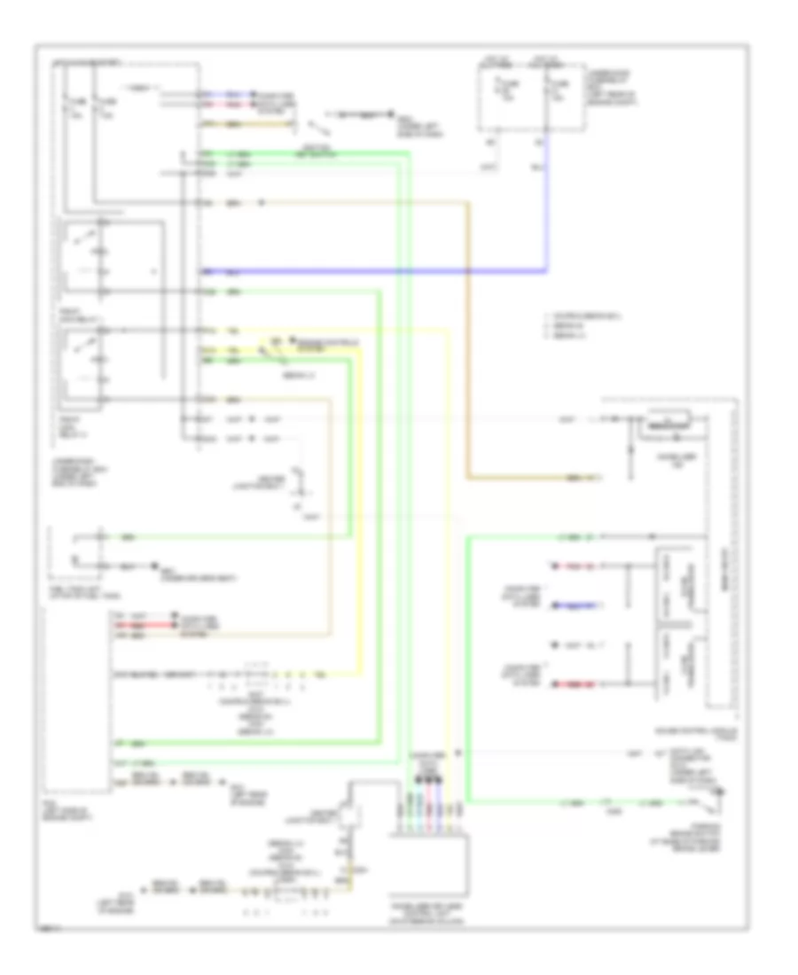
Immobilizer Wiring Diagram, Except Hybrid for Honda Civic LX 2013
 https://portal-diagnostov.com/license.html
Automotive Electricians Portal FZCO
Automotive Electricians Portal FZCO
https://portal-diagnostov.com/license.html
https://portal-diagnostov.com/license.html
Automotive Electricians Portal FZCO
Automotive Electricians Portal FZCOList of elements for Immobilizer Wiring Diagram, Except Hybrid for Honda Civic LX 2013:
- (sedan lx) c404 (sedan si) c410 (coupe & sedan ex-l) c407
- 5v regulator
- A17
- A40
- B-can h
- B-can l
- C10
- C13
- C20
- C204
- C205
- C24
- C25
- C35
- C407 (coupe & sedan ex-l) c410 (sedan si) c404 (sedan lx)
- Center junction box 1
- Computer data lines system
- Coupe & sedan ex-l
- D28
- Data link connector (dlc) (under left side of dash)
- Engine controls system
- F-can h
- F-can l
- Fuel tank unit (in top of fuel tank)
- Fuse 10a
- Fuse 15a
- Fuse 7.5a
- G101 (left rear of engine)
- G503 (under left side of dash)
- G601 (under driver's seat)
- Gauge control module (tach)
- Hot at all times
- Hot in on or start
- Ignition key switch
- Immobilizer ind
- Immobilizer keyless control unit (on steering column)
- Main circuit
- Micu
- P11
- P18
- Parking brake switch (at base of parking brake lever)
- Pcm (left side of engine compt)
- Pgm-fi main relay 1
- Pgm-fi main relay 2
- Pnk
- Q16
- Red
- Sedan lx
- Sedan si
- Transceiver b-can
- Transceiver f-can
- Under-dash fuse/relay box (under left end of dash)
- Under-hood fuse/relay box (left rear of engine compt)
Immobilizer Wiring Diagram, Hybrid for Honda Civic LX 2013
 https://portal-diagnostov.com/license.html
Automotive Electricians Portal FZCO
Automotive Electricians Portal FZCO
https://portal-diagnostov.com/license.html
https://portal-diagnostov.com/license.html
Automotive Electricians Portal FZCO
Automotive Electricians Portal FZCOList of elements for Immobilizer Wiring Diagram, Hybrid for Honda Civic LX 2013:
- A17
- A40
- B-can h
- B-can l
- B10
- C10
- C13
- C206
- C216
- C223
- C24
- C25
- C302
- Center junction box 1
- Computer data lines system
- D28
- Data link connector (dlc) (under left side of dash)
- Engine controls system
- F-can h
- F-can l
- Fuel tank unit (top of fuel tank)
- Fuse 10a
- Fuse 15a
- Fuse 7.5a
- G101 (left rear side of engine)
- G501 (left end of dash)
- G503 (left side of dash)
- G601 (under driver's seat)
- Gauge control module (tach)
- Hot at all times
- Hot in on or start
- Ignition key switch
- Immobilizer ind
- Immobilizer keyless control unit (in steering column)
- Main circuit
- Micu
- P11
- P18
- Parking brake switch (at base of park lever)
- Pcm (left side of engine compt)
- Pgm-fi main relay 1
- Pgm-fi main relay 2 (in under dash fuse/relay box)
- Pnk
- Q16
- Red
- Transceiver b-can
- Transceiver f-can
- Under-dash fuse/relay box (under left end of dash)
- Under-hood fuse/relay box (left rear of engine compt)

 Čeština
 Dansk
Dansk Deutsch
 Ελληνικά
 English
 English
 Español
 Suomi
Suomi Français
 Français
 עברית
עברית Hrvatski
 Magyar
 Italiano
 日本語
日本語 Nederlands
 Polski
 Português
 Português
 Română
 Русский
 Slovenčina
 Slovenščina
 Svenska
 Türkçe
 中文 (中国)
