POWER DISTRIBUTION
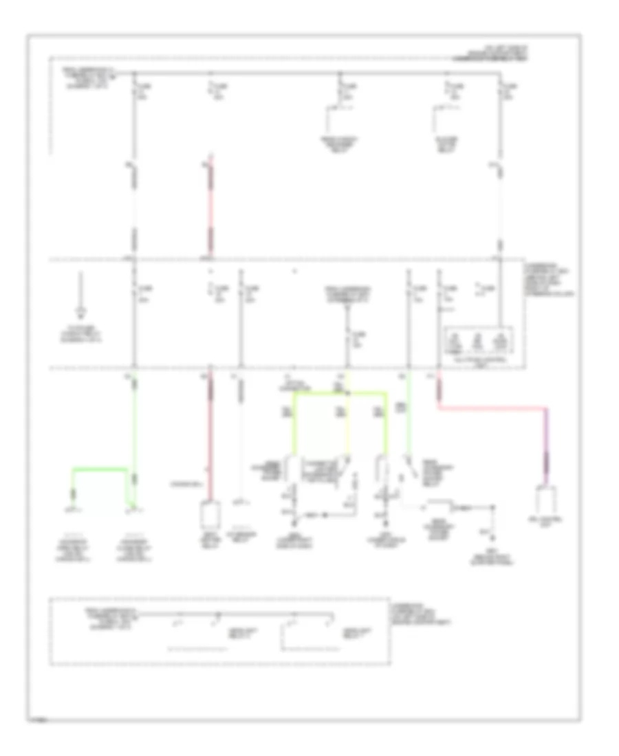
Power Distribution Wiring Diagram (1 of 4) for Honda CR-V LX 2003
 https://portal-diagnostov.com/license.html
Automotive Electricians Portal FZCO
Automotive Electricians Portal FZCO
https://portal-diagnostov.com/license.html
https://portal-diagnostov.com/license.html
Automotive Electricians Portal FZCO
Automotive Electricians Portal FZCO
List of elements for Power Distribution Wiring Diagram (1 of 4) for Honda CR-V LX 2003:
- (not used)
- (on left side of engine compartment) underhood fuse/relay box
- A/c compressor clutch relay
- A/c condenser fan relay
- A10
- Abs modulator control unit (ex, canada: ex-l)
- Alternator
- Audio unit
- B19
- Battery
- Brake pedal position switch
- C10
- D11
- Data link connector (dlc)
- E12
- Eld unit
- From battery a (diagram 1 of 4)
- Front ceiling light
- Fuse 100a
- Fuse 10a
- Fuse 15a
- Fuse 20a
- Fuse 30a
- Fuse 50a
- Fuse 8 (not used)
- Gauge assembly
- Hazard warning switch
- Horn relay
- Ignition key switch/ key light
- Immobilizer control unit- receiver
- K13
- Keyless receiver unit
- Multiplex control unit
- O12
- Pgm-fi main relay 1
- Radiator fan relay
- Rear ceiling light
- Rear wiper control unit
- Spotlights
- Starter
- Starter solenoid
- T101
- T102
- Taillight relay
- To ignition switch (diagram 3 of 4)
- To underhood fuse/relay box (fuse 13, 40a) (diagram 2 of 4)
- To underhood fuse/relay box (fuse 5, 10a) (diagram 1 of 4)
- To underhood fuse/relay box (headlight relay 2) (diagram 2 of 4)
- Trailer lighting connector
- Underdash fuse/relay box (behind left side of dash, right of steering column)
- Underdash fuse/relay box (under left side of dash)
- Underhood fuse/relay box (on left side of engine compartment)
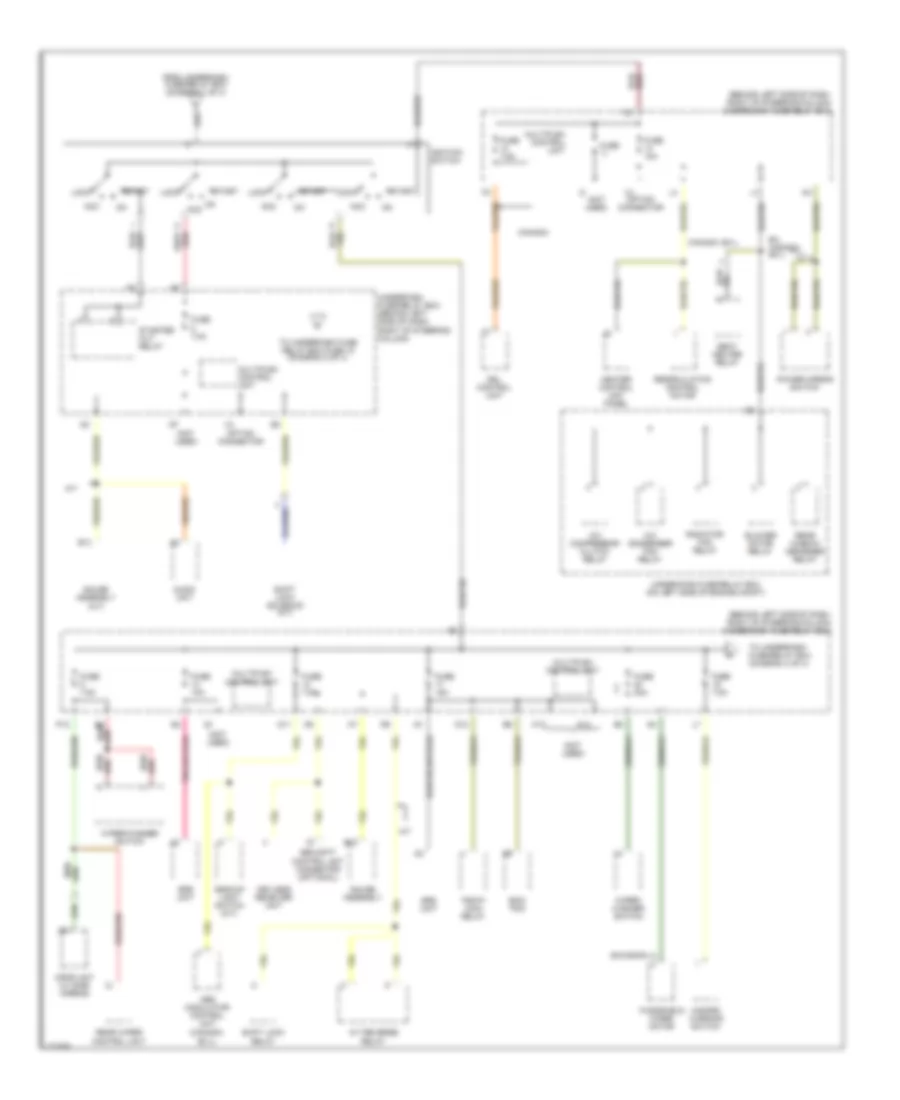
Power Distribution Wiring Diagram (2 of 4) for Honda CR-V LX 2003
 https://portal-diagnostov.com/license.html
Automotive Electricians Portal FZCO
Automotive Electricians Portal FZCO
https://portal-diagnostov.com/license.html
https://portal-diagnostov.com/license.html
Automotive Electricians Portal FZCO
Automotive Electricians Portal FZCOList of elements for Power Distribution Wiring Diagram (2 of 4) for Honda CR-V LX 2003:
- (behind left side of dash right of steering column)
- (on left side of engine compartment) underhood fuse/relay box
- +b day lt/fr fog
- +b door lock
- +b rr fog
- A/f sensor relay
- Blower motor relay
- Canada ex-l
- Cigarette lighter (accessory installed)
- Drl control unit
- From underdash fuse/relay box (diagram 3 of 4)
- From underhood fuse/relay box b (fuse 9, 10a) (diagram 1 of 4)
- From underhood fuse/relay box c (fuse 6, 15a) (diagram 1 of 4)
- Front accessory power socket
- Fuse
- Fuse 10a
- Fuse 15a
- Fuse 20a
- Fuse 40a
- G451 (under middle of dash)
- G502 (under right side of dash)
- G601 (behind right quarter panel)
- Headlight relay 1
- Headlight relay 2
- Moonroof close relay (usa ex, canada ex-l)
- Moonroof open relay (usa ex, canada ex-l)
- Multiplex control unit
- Option connector
- Rear accessory power socket
- Rear accessory power socket relay
- Rear window defogger relay
- Seat heater relay
- To power window relay (diagram 4 of 4)
- Underdash fuse/relay box
- Underhood fuse/relay box (on left side of engine compartment)
Power Distribution Wiring Diagram (3 of 4) for Honda CR-V LX 2003
 https://portal-diagnostov.com/license.html
Automotive Electricians Portal FZCO
Automotive Electricians Portal FZCO
https://portal-diagnostov.com/license.html
https://portal-diagnostov.com/license.html
Automotive Electricians Portal FZCO
Automotive Electricians Portal FZCOList of elements for Power Distribution Wiring Diagram (3 of 4) for Honda CR-V LX 2003:
- (behind left side of dash, right of steering column) underdash fuse/relay box
- (not used)
- (swindon)
- A/c compressor clutch relay
- A/c condenser fan relay
- A/t
- A/t reverse relay
- Abs modulator control unit (canada: ex-l)
- Acc
- Audio unit
- B13
- B18
- B4 red/
- Backup light switch (m/t)
- Blower motor relay
- Canada
- Canada: ex-l
- D11
- D12
- Drl control unit
- Ecm/ pcm
- Ex, canada: ex-l
- From underdash fuse/relay box (diagram 1 of 4)
- Fuse
- Fuse 10a
- Fuse 15a
- Fuse 20a
- Fuse 7.5a
- Gauge assembly
- Gauge assembly (a/t)
- Hazard warning switch
- Heater control unit panel
- Ignition switch
- K12
- K14
- Keyless receiver unit
- Lock
- Multiplex control unit
- Opds unit (w/ side airbag)
- Option connector
- P12
- Pgm-fi main relay
- Power mirror switch
- Radiator fan relay
- Rear window defogger relay
- Rear wiper control unit
- Recirculation control motor
- Red/
- Seat heater relay
- Security control unit connector (optional)
- Shift lock relay
- Shift lock solenoid (a/t)
- Srs unit
- Start
- Starter cut relay
- To underdash fuse/relay box (diagram 4 of 4)
- To underdash fuse relay box fuse 18 (diagram 2 of 4)
- Underdash fuse/relay box (behind left side of dash, right of steering column)
- Underhood fuse/relay box (on left side of engine compt)
- Windshield wiper motor
- Wiper/ washer switch
- Wiper/washer switch
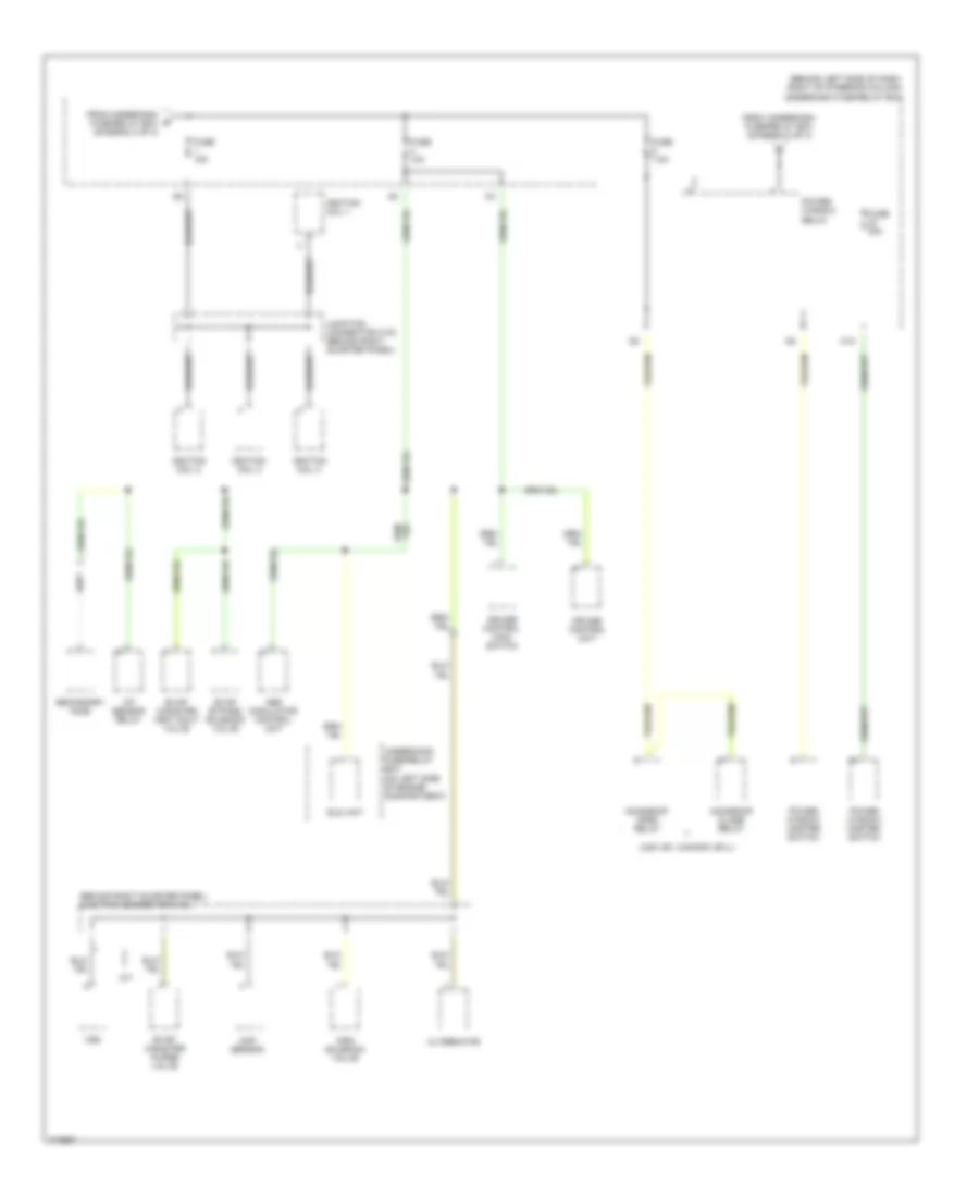
Power Distribution Wiring Diagram (4 of 4) for Honda CR-V LX 2003
 https://portal-diagnostov.com/license.html
Automotive Electricians Portal FZCO
Automotive Electricians Portal FZCO
https://portal-diagnostov.com/license.html
https://portal-diagnostov.com/license.html
Automotive Electricians Portal FZCO
Automotive Electricians Portal FZCOList of elements for Power Distribution Wiring Diagram (4 of 4) for Honda CR-V LX 2003:
- (behind left side of dash, right of steering column) underdash fuse/relay box
- (behind right quarter panel) junction connector c103
- (usa: ex, canada: ex-l)
- A/f sensor relay
- Abs modulator control unit
- Alternator
- Cmp sensor
- Cruise control main switch
- Cruise control unit
- Eld unit
- Evap bypass solenoid valve
- Evap canister purge valve
- Evap canister vent shut valve
- From underdash fuse/relay box (diagram 2 of 4)
- From underdash g fuse/relay box (diagram 3 of 4)
- Fuse 10a
- Fuse 15a
- Fuse 20a
- Fuse 7.5a
- Ignition coil 1
- Ignition coil 2
- Ignition coil 3
- Ignition coil 4
- Imrc solenoid valve
- Junction connector c103 (behind right quarter panel)
- M/t
- M10
- Moonroof close relay
- Moonroof open relay
- Power window master switch
- Power window relay
- Secondary ho2s
- Underhood fuse/relay box (on left side of engine compartment)
- Vss

 Čeština
 Dansk
Dansk Deutsch
 Ελληνικά
 English
 English
 Español
 Suomi
Suomi Français
 Français
 עברית
עברית Hrvatski
 Magyar
 Italiano
 日本語
日本語 Nederlands
 Polski
 Português
 Português
 Română
 Русский
 Slovenčina
 Slovenščina
 Svenska
 Türkçe
 中文 (中国)
