AIR CONDITIONING
4.9L
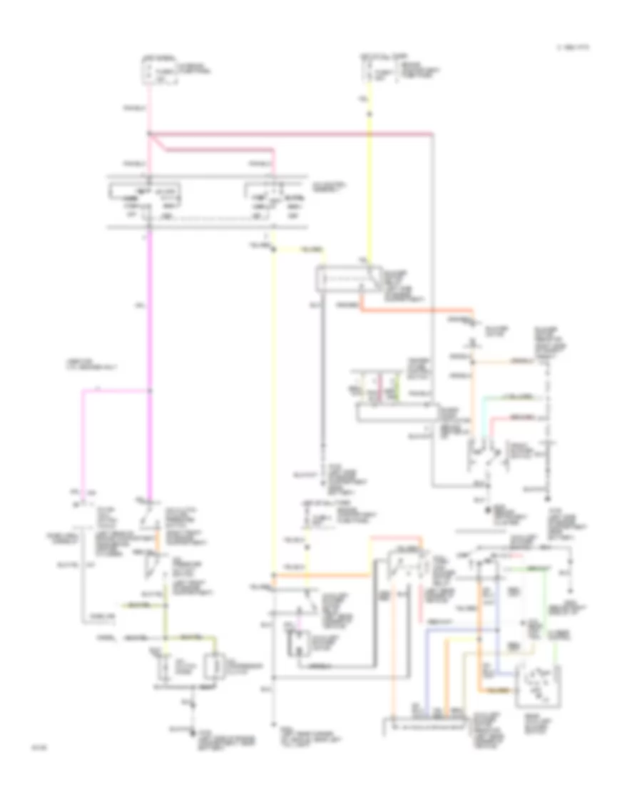
4.9L, A/C Wiring Diagram, California for Ford Club Wagon E150 1995
 https://portal-diagnostov.com/license.html
Automotive Electricians Portal FZCO
Automotive Electricians Portal FZCO
https://portal-diagnostov.com/license.html
https://portal-diagnostov.com/license.html
Automotive Electricians Portal FZCO
Automotive Electricians Portal FZCO
List of elements for 4.9L, A/C Wiring Diagram, California for Ford Club Wagon E150 1995:
- (behind right side of i/p)
- (left front of engine compartment)
- (left rear corner of vehicle)
- (left rear of engine compartment
- (right front of engine compartment)
- (right side of safety wall)
- 15a
- A/c pressure cut out switch
- A/c clutch cycling pressure switch
- A/c clutch diode
- A/c compressor clutch
- A/c control assembly
- Aux- iliary high blower motor relay
- Auxiliary blower motor
- Auxiliary blower motor relay (left rear corner of vehicle)
- Auxiliary blower motor resistor (left rear corner of vehicle)
- Auxiliary blower switch
- Blend door actuator (behind center of i/p)
- Blower motor
- Blower motor relay (left side of engine compartment)
- Blower motor resistor
- C 1995 vftc
- Def
- Engine compartment fuse panel
- Floor
- Front blower switch
- Fuse 9
- Fuse a 60a
- Fuse f 60a
- G108 (left side of engine compartment near battery)
- G108 (left side of engine compartment, near battery)
- G202
- G206 (behind instrument cluster)
- G404 (left rear corner of vehicle, near left tail light)
- Hot at all times
- Hot in run
- Interior fuse panel
- Lo/ rear
- Max
- Mix
- Near brake master cylinder)
- Norm
- Off
- Pcm power relay
- Power- train control module
- Rear auxiliary blower switch
- Red
- Temper- ature control switch
- Vent
- W/ rear control
- W/o rear con- trol
- Wide open throttle relay (lower left side of engine compartment)
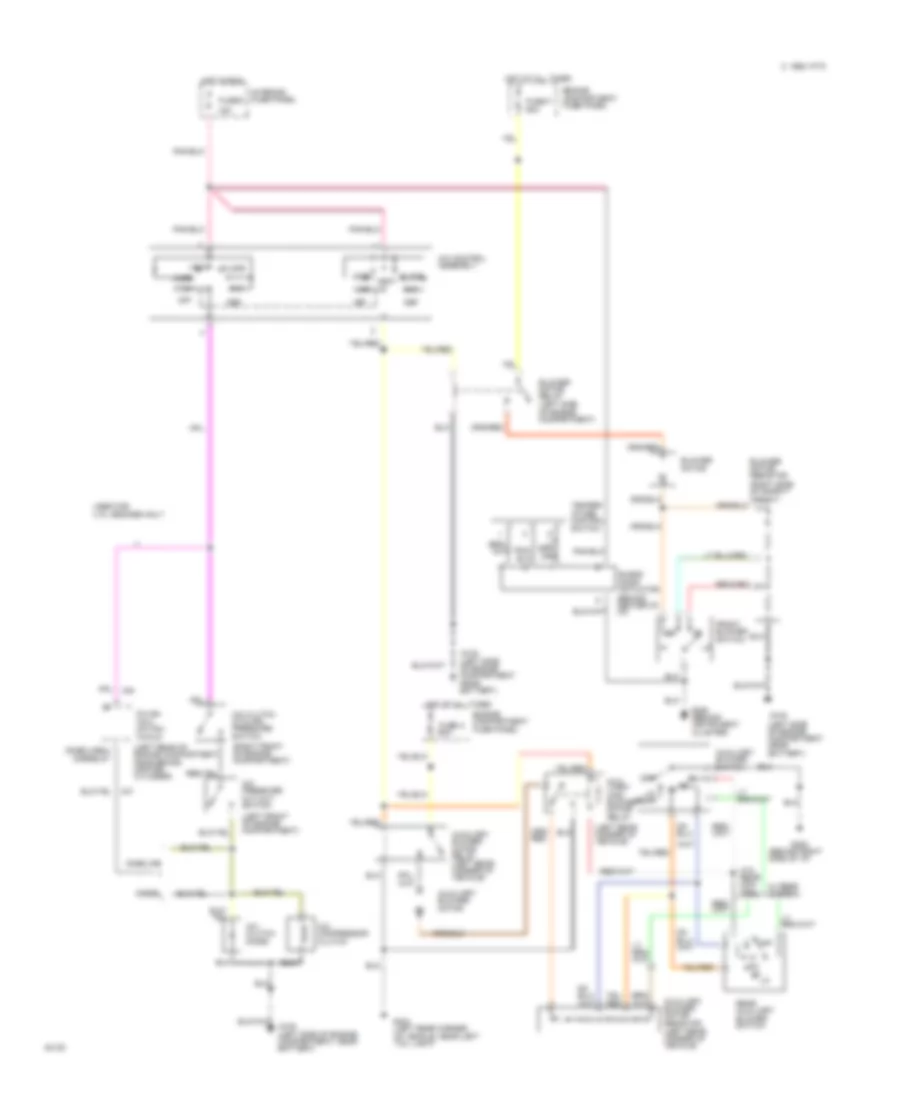
4.9L, A/C Wiring Diagram, Federal for Ford Club Wagon E150 1995
 https://portal-diagnostov.com/license.html
Automotive Electricians Portal FZCO
Automotive Electricians Portal FZCO
https://portal-diagnostov.com/license.html
https://portal-diagnostov.com/license.html
Automotive Electricians Portal FZCO
Automotive Electricians Portal FZCOList of elements for 4.9L, A/C Wiring Diagram, Federal for Ford Club Wagon E150 1995:
- (behind right side of i/p)
- (diesel)
- (gasoline)
- (left front of engine compartment)
- (left rear corner of vehicle)
- (left rear of engine compartment near brake master cylinder)
- (right front of engine compartment)
- (right side of safety wall)
- 15a
- A/c pressure cut out switch
- A/c clutch cycling pressure switch
- A/c clutch diode
- A/c compressor clutch
- A/c control assembly
- Aux- iliary high blower motor relay
- Auxiliary blower motor
- Auxiliary blower motor relay (left rear corner of vehicle)
- Auxiliary blower motor resistor (left rear corner of vehicle)
- Auxiliary blower switch
- Blend door actuator (behind center of i/p)
- Blower motor
- Blower motor relay (left side of engine compartment)
- Blower motor resistor
- C 1995 vftc
- Def
- Diesel
- Engine compartment fuse panel
- Floor
- Front blower switch
- Fuse 9
- Fuse a 60a
- Fuse f 60a
- G108 (left side of engine compartment near battery)
- G108 (left side of engine compartment, near battery)
- G202
- G206 (behind instrument cluster)
- G404 (left rear corner of vehicle, near left tail light)
- Gasoline
- Hot at all times
- Hot in run
- Interior fuse panel
- Max
- Mix
- Norm
- Off
- Power- train control module
- Rear auxiliary blower switch
- Temper- ature control switch
- Used for 4.9 l engines only
- Vent
- W/ rear control
- W/o rear con- trol
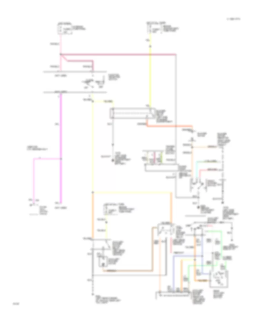
4.9L, Heater Wiring Diagram for Ford Club Wagon E150 1995
 https://portal-diagnostov.com/license.html
Automotive Electricians Portal FZCO
Automotive Electricians Portal FZCO
https://portal-diagnostov.com/license.html
https://portal-diagnostov.com/license.html
Automotive Electricians Portal FZCO
Automotive Electricians Portal FZCOList of elements for 4.9L, Heater Wiring Diagram for Ford Club Wagon E150 1995:
- (behind right side of i/p)
- (left rear corner of vehicle)
- (not used)
- (right side of safety wall)
- 15a
- Aux- iliary high blower motor relay
- Auxiliary blower motor
- Auxiliary blower motor relay (left rear corner of vehicle)
- Auxiliary blower motor resistor (left rear corner of vehicle)
- Auxiliary blower switch
- Blend door actuator (behind center of i/p)
- Blower motor
- Blower motor relay (left side of engine compartment)
- Blower motor resistor
- C 1995 vftc
- Def
- Engine compartment fuse panel
- Floor
- Front blower switch
- Function selector switch
- Fuse 9
- Fuse a 60a
- Fuse f 60a
- G108 (left side of engine compartment near battery)
- G202
- G206 (behind instrument cluster)
- G404 (left rear corner of vehicle, near left tail light)
- Hot at all times
- Hot in run
- Interior fuse panel
- Mix
- Off
- Power- train control module
- Rear auxiliary blower switch
- Temper- ature control switch
- Used for 4.9 l engines only
- Vent
- W/ rear control
- W/o rear con- trol
5.0L
5.0L, A/C Wiring Diagram for Ford Club Wagon E150 1995
 https://portal-diagnostov.com/license.html
Automotive Electricians Portal FZCO
Automotive Electricians Portal FZCO
https://portal-diagnostov.com/license.html
https://portal-diagnostov.com/license.html
Automotive Electricians Portal FZCO
Automotive Electricians Portal FZCOList of elements for 5.0L, A/C Wiring Diagram for Ford Club Wagon E150 1995:
- (behind right side of i/p)
- (diesel)
- (gasoline)
- (left front of engine compartment)
- (left rear corner of vehicle)
- (left rear of engine compartment near brake master cylinder)
- (right front of engine compartment)
- (right side of safety wall)
- 15a
- A/c pressure cut out switch
- A/c clutch cycling pressure switch
- A/c clutch diode
- A/c compressor clutch
- A/c control assembly
- Aux- iliary high blower motor relay
- Auxiliary blower motor
- Auxiliary blower motor relay (left rear corner of vehicle)
- Auxiliary blower motor resistor (left rear corner of vehicle)
- Auxiliary blower switch
- Blend door actuator (behind center of i/p)
- Blower motor
- Blower motor relay (left side of engine compartment)
- Blower motor resistor
- C 1995 vftc
- Def
- Diesel
- Engine compartment fuse panel
- Floor
- Front blower switch
- Fuse 9
- Fuse a 60a
- Fuse f 60a
- G108 (left side of engine compartment near battery)
- G108 (left side of engine compartment, near battery)
- G202
- G206 (behind instrument cluster)
- G404 (left rear corner of vehicle, near left tail light)
- Gasoline
- Hot at all times
- Hot in run
- Interior fuse panel
- Lo/ rear
- Max
- Mix
- Norm
- Off
- Power- train control module
- Rear auxiliary blower switch
- Temper- ature control switch
- Used for 4.9 l engines only
- Vent
- W/ rear control
- W/o rear con- trol
5.0L, Heater Wiring Diagram for Ford Club Wagon E150 1995
 https://portal-diagnostov.com/license.html
Automotive Electricians Portal FZCO
Automotive Electricians Portal FZCO
https://portal-diagnostov.com/license.html
https://portal-diagnostov.com/license.html
Automotive Electricians Portal FZCO
Automotive Electricians Portal FZCOList of elements for 5.0L, Heater Wiring Diagram for Ford Club Wagon E150 1995:
- (behind right side of i/p)
- (left rear corner of vehicle)
- (not used)
- (right side of safety wall)
- 15a
- Aux- iliary high blower motor relay
- Auxiliary blower motor
- Auxiliary blower motor relay (left rear corner of vehicle)
- Auxiliary blower motor resistor (left rear corner of vehicle)
- Auxiliary blower switch
- Blend door actuator (behind center of i/p)
- Blower motor
- Blower motor relay (left side of engine compartment)
- Blower motor resistor
- C 1995 vftc
- Def
- Engine compartment fuse panel
- Floor
- Front blower switch
- Function selector switch
- Fuse 9
- Fuse a 60a
- Fuse f 60a
- G108 (left side of engine compartment near battery)
- G202
- G206 (behind instrument cluster)
- G404 (left rear corner of vehicle, near left tail light)
- Hot at all times
- Hot in run
- Interior fuse panel
- Mix
- Off
- Power- train control module
- Rear auxiliary blower switch
- Temper- ature control switch
- Used for 4.9 l engines only
- Vent
- W/ rear control
- W/o rear con- trol
5.8L
5.8L, A/C Wiring Diagram for Ford Club Wagon E150 1995
 https://portal-diagnostov.com/license.html
Automotive Electricians Portal FZCO
Automotive Electricians Portal FZCO
https://portal-diagnostov.com/license.html
https://portal-diagnostov.com/license.html
Automotive Electricians Portal FZCO
Automotive Electricians Portal FZCOList of elements for 5.8L, A/C Wiring Diagram for Ford Club Wagon E150 1995:
- (behind right side of i/p)
- (diesel)
- (gasoline)
- (left front of engine compartment)
- (left rear corner of vehicle)
- (left rear of engine compartment near brake master cylinder)
- (right front of engine compartment)
- (right side of safety wall)
- 15a
- A/c pressure cut out switch
- A/c clutch cycling pressure switch
- A/c clutch diode
- A/c compressor clutch
- A/c control assembly
- Aux- iliary high blower motor relay
- Auxiliary blower motor
- Auxiliary blower motor relay (left rear corner of vehicle)
- Auxiliary blower motor resistor (left rear corner of vehicle)
- Auxiliary blower switch
- Blend door actuator (behind center of i/p)
- Blower motor
- Blower motor relay (left side of engine compartment)
- Blower motor resistor
- C 1995 vftc
- Def
- Diesel
- Engine compartment fuse panel
- Floor
- Front blower switch
- Fuse 9
- Fuse a 60a
- Fuse f 60a
- G108 (left side of engine compartment near battery)
- G108 (left side of engine compartment, near battery)
- G202
- G206 (behind instrument cluster)
- G404 (left rear corner of vehicle, near left tail light)
- Gasoline
- Hot at all times
- Hot in run
- Interior fuse panel
- Lo/ rear
- Max
- Mix
- Norm
- Off
- Power- train control module
- Rear auxiliary blower switch
- Temper- ature control switch
- Used for 4.9 l engines only
- Vent
- W/ rear control
- W/o rear con- trol
5.8L, Heater Wiring Diagram for Ford Club Wagon E150 1995
 https://portal-diagnostov.com/license.html
Automotive Electricians Portal FZCO
Automotive Electricians Portal FZCO
https://portal-diagnostov.com/license.html
https://portal-diagnostov.com/license.html
Automotive Electricians Portal FZCO
Automotive Electricians Portal FZCOList of elements for 5.8L, Heater Wiring Diagram for Ford Club Wagon E150 1995:
- (behind right side of i/p)
- (left rear corner of vehicle)
- (not used)
- (right side of safety wall)
- 15a
- Aux- iliary high blower motor relay
- Auxiliary blower motor
- Auxiliary blower motor relay (left rear corner of vehicle)
- Auxiliary blower motor resistor (left rear corner of vehicle)
- Auxiliary blower switch
- Blend door actuator (behind center of i/p)
- Blower motor
- Blower motor relay (left side of engine compartment)
- Blower motor resistor
- C 1995 vftc
- Def
- Engine compartment fuse panel
- Floor
- Front blower switch
- Function selector switch
- Fuse 9
- Fuse a 60a
- Fuse f 60a
- G108 (left side of engine compartment near battery)
- G202
- G206 (behind instrument cluster)
- G404 (left rear corner of vehicle, near left tail light)
- Hot at all times
- Hot in run
- Interior fuse panel
- Mix
- Off
- Power- train control module
- Rear auxiliary blower switch
- Temper- ature control switch
- Used for 4.9 l engines only
- Vent
- W/ rear control
- W/o rear con- trol
7.3L
7.3L Diesel, A/C Wiring Diagram for Ford Club Wagon E150 1995
 https://portal-diagnostov.com/license.html
Automotive Electricians Portal FZCO
Automotive Electricians Portal FZCO
https://portal-diagnostov.com/license.html
https://portal-diagnostov.com/license.html
Automotive Electricians Portal FZCO
Automotive Electricians Portal FZCOList of elements for 7.3L Diesel, A/C Wiring Diagram for Ford Club Wagon E150 1995:
- (behind right side of i/p)
- (diesel)
- (gasoline)
- (left front of engine compartment)
- (left rear corner of vehicle)
- (left rear of engine compartment near brake master cylinder)
- (right front of engine compartment)
- (right side of safety wall)
- 15a
- A/c pressure cut out switch
- A/c clutch cycling pressure switch
- A/c clutch diode
- A/c compressor clutch
- A/c control assembly
- Aux- iliary high blower motor relay
- Auxiliary blower motor
- Auxiliary blower motor relay (left rear corner of vehicle)
- Auxiliary blower motor resistor (left rear corner of vehicle)
- Auxiliary blower switch
- Blend door actuator (behind center of i/p)
- Blower motor
- Blower motor relay (left side of engine compartment)
- Blower motor resistor
- C 1995 vftc
- Def
- Diesel
- Engine compartment fuse panel
- Floor
- Front blower switch
- Fuse 9
- Fuse a 60a
- Fuse f 60a
- G108 (left side of engine compartment near battery)
- G108 (left side of engine compartment, near battery)
- G202
- G206 (behind instrument cluster)
- G404 (left rear corner of vehicle, near left tail light)
- Gasoline
- Hot at all times
- Hot in run
- Interior fuse panel
- Lo/ rear
- Max
- Mix
- Norm
- Off
- Power- train control module
- Rear auxiliary blower switch
- Temper- ature control switch
- Used for 4.9 l engines only
- Vent
- W/ rear control
- W/o rear con- trol
7.3L Diesel, Heater Wiring Diagram for Ford Club Wagon E150 1995
 https://portal-diagnostov.com/license.html
Automotive Electricians Portal FZCO
Automotive Electricians Portal FZCO
https://portal-diagnostov.com/license.html
https://portal-diagnostov.com/license.html
Automotive Electricians Portal FZCO
Automotive Electricians Portal FZCOList of elements for 7.3L Diesel, Heater Wiring Diagram for Ford Club Wagon E150 1995:
- (behind right side of i/p)
- (left rear corner of vehicle)
- (not used)
- (right side of safety wall)
- 15a
- Aux- iliary high blower motor relay
- Auxiliary blower motor
- Auxiliary blower motor relay (left rear corner of vehicle)
- Auxiliary blower motor resistor (left rear corner of vehicle)
- Auxiliary blower switch
- Blend door actuator (behind center of i/p)
- Blower motor
- Blower motor relay (left side of engine compartment)
- Blower motor resistor
- C 1995 vftc
- Def
- Engine compartment fuse panel
- Floor
- Front blower switch
- Function selector switch
- Fuse 9
- Fuse a 60a
- Fuse f 60a
- G108 (left side of engine compartment near battery)
- G202
- G206 (behind instrument cluster)
- G404 (left rear corner of vehicle, near left tail light)
- Hot at all times
- Hot in run
- Interior fuse panel
- Mix
- Off
- Power- train control module
- Rear auxiliary blower switch
- Temper- ature control switch
- Used for 4.9 l engines only
- Vent
- W/ rear control
- W/o rear con- trol
7.5L
7.5L, A/C Wiring Diagram for Ford Club Wagon E150 1995
 https://portal-diagnostov.com/license.html
Automotive Electricians Portal FZCO
Automotive Electricians Portal FZCO
https://portal-diagnostov.com/license.html
https://portal-diagnostov.com/license.html
Automotive Electricians Portal FZCO
Automotive Electricians Portal FZCOList of elements for 7.5L, A/C Wiring Diagram for Ford Club Wagon E150 1995:
- (behind right side of i/p)
- (diesel)
- (gasoline)
- (left front of engine compartment)
- (left rear corner of vehicle)
- (left rear of engine compartment near brake master cylinder)
- (right front of engine compartment)
- (right side of safety wall)
- 15a
- A/c pressure cut out switch
- A/c clutch cycling pressure switch
- A/c clutch diode
- A/c compressor clutch
- A/c control assembly
- Aux- iliary high blower motor relay
- Auxiliary blower motor
- Auxiliary blower motor relay (left rear corner of vehicle)
- Auxiliary blower motor resistor (left rear corner of vehicle)
- Auxiliary blower switch
- Blend door actuator (behind center of i/p)
- Blower motor
- Blower motor relay (left side of engine compartment)
- Blower motor resistor
- C 1995 vftc
- Def
- Diesel
- Engine compartment fuse panel
- Floor
- Front blower switch
- Fuse 9
- Fuse a 60a
- Fuse f 60a
- G108 (left side of engine compartment near battery)
- G108 (left side of engine compartment, near battery)
- G202
- G206 (behind instrument cluster)
- G404 (left rear corner of vehicle, near left tail light)
- Gasoline
- Hot at all times
- Hot in run
- Interior fuse panel
- Lo/ rear
- Max
- Mix
- Norm
- Off
- Power- train control module
- Rear auxiliary blower switch
- Temper- ature control switch
- Used for 4.9 l engines only
- Vent
- W/ rear control
- W/o rear con- trol
7.5L, Heater Wiring Diagram for Ford Club Wagon E150 1995
 https://portal-diagnostov.com/license.html
Automotive Electricians Portal FZCO
Automotive Electricians Portal FZCO
https://portal-diagnostov.com/license.html
https://portal-diagnostov.com/license.html
Automotive Electricians Portal FZCO
Automotive Electricians Portal FZCOList of elements for 7.5L, Heater Wiring Diagram for Ford Club Wagon E150 1995:
- (behind right side of i/p)
- (left rear corner of vehicle)
- (not used)
- (right side of safety wall)
- 15a
- Aux- iliary high blower motor relay
- Auxiliary blower motor
- Auxiliary blower motor relay (left rear corner of vehicle)
- Auxiliary blower motor resistor (left rear corner of vehicle)
- Auxiliary blower switch
- Blend door actuator (behind center of i/p)
- Blower motor
- Blower motor relay (left side of engine compartment)
- Blower motor resistor
- C 1995 vftc
- Def
- Engine compartment fuse panel
- Floor
- Front blower switch
- Function selector switch
- Fuse 9
- Fuse a 60a
- Fuse f 60a
- G108 (left side of engine compartment near battery)
- G202
- G206 (behind instrument cluster)
- G404 (left rear corner of vehicle, near left tail light)
- Hot at all times
- Hot in run
- Interior fuse panel
- Mix
- Off
- Power- train control module
- Rear auxiliary blower switch
- Temper- ature control switch
- Used for 4.9 l engines only
- Vent
- W/ rear control
- W/o rear con- trol

 Čeština
 Dansk
Dansk Deutsch
 Ελληνικά
 English
 English
 Español
 Suomi
Suomi Français
 Français
 עברית
עברית Hrvatski
 Magyar
 Italiano
 日本語
日本語 Nederlands
 Polski
 Português
 Português
 Română
 Русский
 Slovenčina
 Slovenščina
 Svenska
 Türkçe
 中文 (中国)
