AIR CONDITIONING
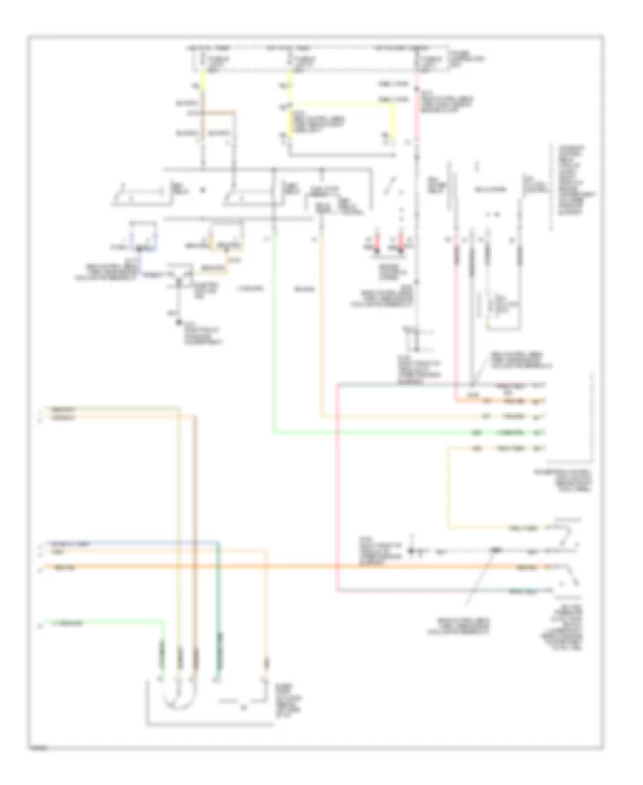
A/C Wiring Diagram, Auto A/C (1 of 2) for Ford Thunderbird LX 1997
 https://portal-diagnostov.com/license.html
Automotive Electricians Portal FZCO
Automotive Electricians Portal FZCO
https://portal-diagnostov.com/license.html
https://portal-diagnostov.com/license.html
Automotive Electricians Portal FZCO
Automotive Electricians Portal FZCO
List of elements for A/C Wiring Diagram, Auto A/C (1 of 2) for Ford Thunderbird LX 1997:
- 2 std fuse 5a
- 30a
- A/c clutch cycling pressure switch (right rear of engine compartment on accumulator)
- A/c fuse 10a
- Acc
- Atc ambient temperature sensor (right front of vehicle, on lower radiator support)
- Blower in-line fuse holder (behind left side of i/p, taped to harness)
- Blower motor
- Blower motor speed controller (behind right side of i/p)
- C232
- C233
- C240
- C258
- C259
- C260
- C298
- Cold engine lockout switch (top right side of engine)
- Def
- Flr
- Flr/def
- G202 (behind i/p, right of steering column)
- G203 (behind right cowl panel)
- Hot at all times
- Hot in run
- Ignition switch
- In-car temperature sensor (behind top left side of i/p)
- Interior lights system
- J/c 1
- Junction connector
- Lock
- Max
- Norm
- Norm panel
- Off
- Off pan/flr
- Outside/ recirculate solenoid (behind right side of i/p)
- Pan/flr flr
- Panel
- Power distribution box
- Primary junction block
- Run
- Run fuse 5a
- S209 (main harn, behind left side of i/p)
- Secondary junction block
- Semi-automatic temperature control module (center of i/p)
- Solid state
- Start
- Sunload sensor (behind right top of i/p)
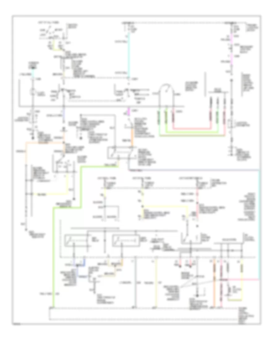
A/C Wiring Diagram, Auto A/C (2 of 2) for Ford Thunderbird LX 1997
 https://portal-diagnostov.com/license.html
Automotive Electricians Portal FZCO
Automotive Electricians Portal FZCO
https://portal-diagnostov.com/license.html
https://portal-diagnostov.com/license.html
Automotive Electricians Portal FZCO
Automotive Electricians Portal FZCOList of elements for A/C Wiring Diagram, Auto A/C (2 of 2) for Ford Thunderbird LX 1997:
- (eng control sens harn, near engine cooling fan breakout)
- A/c clutch coil
- A/c clutch control
- A/c high pressure cutout/fan switch (lower right rear of engine compartment on a/c line)
- Blend door actuator (behind left side of i/p)
- Constant control relay module (ccrm) (right front of engine compartment on upper radiator support
- Edf relay
- Edf relay control
- Electric cooling fan
- Engine controls system
- Fuel pump relay
- Fusible link 15 20a
- Fusible link 3 20a
- Fusible link 5 60a
- G101 (right front of engine compartment)
- G109 (right front of vehicle, on upper radiator support)
- Hedf relay
- Hot at all times
- Hot in start or run
- Pcm power relay
- Power distribution box
- Powertrain control module (pcm) (behind right cowl panel)
- Red
- S123
- S124 (eng control sens harn, behind right headlight)
- S125
- S125 (eng control sens harn, near engine cooling fan breakout)
- S126
- S170 (eng control sens harn, right side of engine compt)
- S177 (eng control sens harn, near engine cooling fan breakout)
- Solid state
A/C Wiring Diagram, Manual A/C for Ford Thunderbird LX 1997
 https://portal-diagnostov.com/license.html
Automotive Electricians Portal FZCO
Automotive Electricians Portal FZCO
https://portal-diagnostov.com/license.html
https://portal-diagnostov.com/license.html
Automotive Electricians Portal FZCO
Automotive Electricians Portal FZCOList of elements for A/C Wiring Diagram, Manual A/C for Ford Thunderbird LX 1997:
- (behind right
- (eng control sens harn, near eng cooling fan motor breakout)
- (right front of engine compartment on upper radiator support)
- 30a
- A/c clutch coil
- A/c clutch control
- A/c clutch cycling pressure switch (right rear of engine compartment on accumulator)
- A/c fuse 10a
- A/c high pressure cutout/fan switch (lower right rear of engine on a/c line)
- A/c-heater function selector switch
- Acc
- Blend door motor control (behind left side of i/p)
- Blower in-line fuse holder (behind left side of i/p, taped to harness)
- Blower motor
- Blower motor switch
- Blower resistors (behind right side of i/p, in plenum)
- C2001
- C2003
- C211
- C232
- C233
- C263
- C298
- Cold
- Constant control relay module (ccrm)
- Def
- Def/flr
- Edf relay
- Edf relay control
- Electric cooling fan
- Engine controls system
- Flr
- Fuel pump relay
- Fusible link 15 20a
- Fusible link 3 20a
- Fusible link 5 60a
- G101 (right front of engine compartment)
- G109 (right front of vehicle, on upper radiator support)
- G202 (behind i/p, right side of steering column)
- G203
- G203 (behind right side of i/p)
- G205 (behind i/p, right side of steering column)
- Hedf relay
- Hot at all times
- Hot in run
- Hot in start or run
- Ignition switch
- Illumi- nation
- Interior lights system
- Junction connector
- Lock
- Max
- Nca
- Norm
- Off
- Pan/flr
- Panel
- Pcm power relay
- Power distribution box
- Power- train control module (pcm) (behind right cowl)
- Primary junction block
- Red
- Run
- Run fuse 5a
- S123
- S124 (engine control sens harn, behind right headlight)
- S125
- S126
- S177 (eng control sens harn, near eng cooling fan motor breakout)
- S178
- S209 (main harn, behind left side of i/p)
- Secondary junction block
- Side of i/p)
- Solid state
- Start
- Warm

 Čeština
 Dansk
Dansk Deutsch
 Ελληνικά
 English
 English
 Español
 Suomi
Suomi Français
 Français
 עברית
עברית Hrvatski
 Magyar
 Italiano
 日本語
日本語 Nederlands
 Polski
 Português
 Português
 Română
 Русский
 Slovenčina
 Slovenščina
 Svenska
 Türkçe
 中文 (中国)
