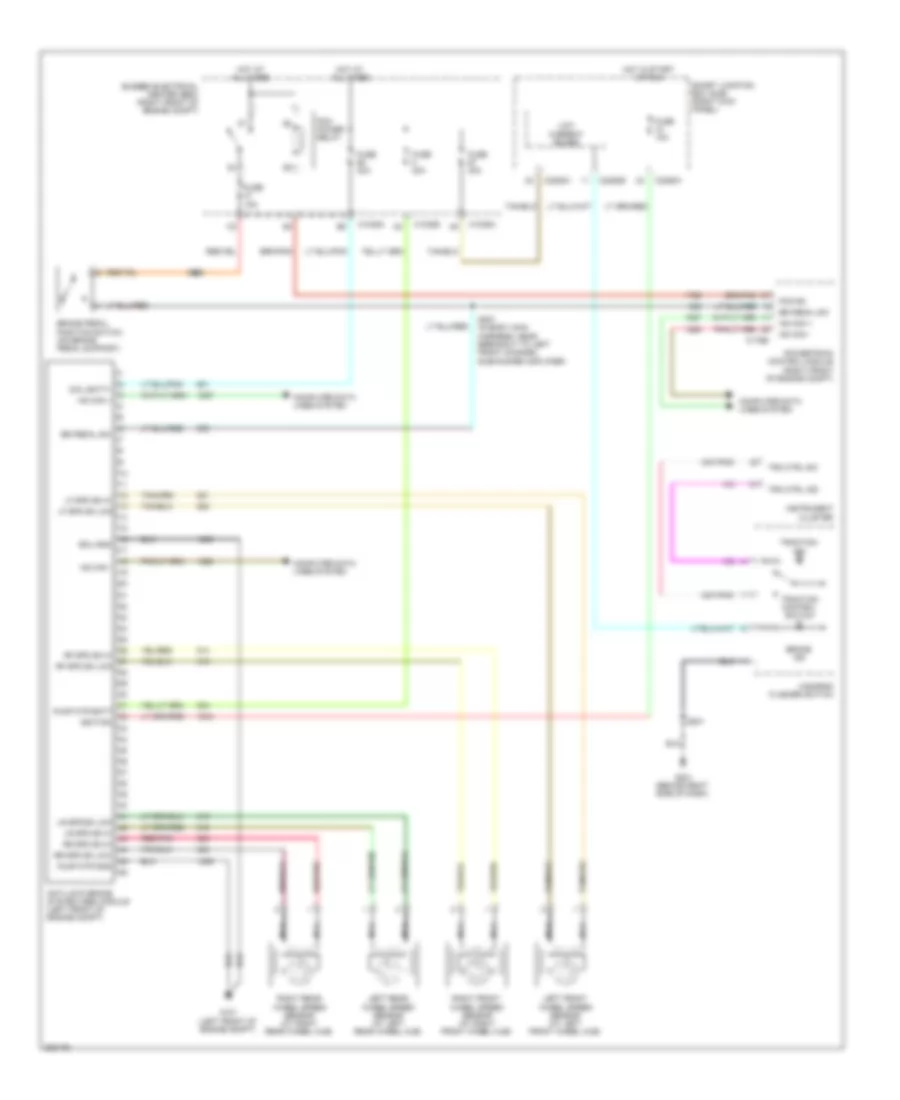
ANTI-LOCK BRAKES
Anti-lock Brakes Wiring Diagram for Ford Mustang GT 2009
 https://portal-diagnostov.com/license.html
Automotive Electricians Portal FZCO
Automotive Electricians Portal FZCO
https://portal-diagnostov.com/license.html
https://portal-diagnostov.com/license.html
Automotive Electricians Portal FZCO
Automotive Electricians Portal FZCO
List of elements for Anti-lock Brakes Wiring Diagram for Ford Mustang GT 2009:
- Anti-lock brake system (abs) module (left front of engine compt)
- Br pedal sw
- Brake ind
- Brake pedal position switch (on brake pedal support)
- Bussed electrical center (bec) (right front of engine compt)
- C1035a
- C1035d
- C175b
- C2280b
- C2280h
- Coil batt+
- Computer data lines system
- Ecu gnd
- Fuse 10a
- Fuse 15a
- Fuse 30a
- Fuse 40a
- G101 (left front of engine compt)
- G201 (behind right side of dash)
- Hazarad flasher switch
- Hot at all times
- Hot in start or run
- Hs can +
- Hs can -
- Ignition
- Instrument cluster
- Left front wheel speed sensor (at left front wheel hub)
- Left rear wheel speed sensor (at left rear wheel hub)
- Lf spd sn hi
- Lf spd sn low
- Low current board
- Lr spd sn hi
- Lr spd sn low
- Nca
- Pcm power relay
- Pcm rc
- Powertrain control module (right front of engine compt)
- Pump mtr batt
- Pump mtr gnd
- Red/pnk
- Rf spd sn hi
- Rf spd sn low
- Right front wheel speed sensor (at right front wheel hub)
- Right rear wheel speed sensor (at right rear wheel hub)
- Rr spd sn hi
- Rr spd sn low
- S201
- S225
- S227 (in body main harness, near breakout to left front channel subwoofer amplifier)
- Smart junction box (sjb) (right kick panel)
- Tra ctrl ind
- Tra ctrl sw
- Traction control switch
- Traction ind
 Čeština
 Dansk
Dansk Deutsch
 Ελληνικά
 English
 English
 Español
 Suomi
Suomi Français
 Français
 עברית
עברית Hrvatski
 Magyar
 Italiano
 日本語
日本語 Nederlands
 Polski
 Português
 Português
 Română
 Русский
 Slovenčina
 Slovenščina
 Svenska
 Türkçe
 中文 (中国)
 한국어
한국어
