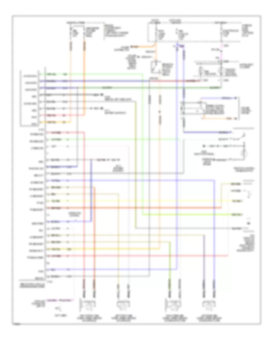
ANTI-LOCK BRAKES
Anti-lock Brake Wiring Diagrams for Mercury Mystique GS 1995
 https://portal-diagnostov.com/license.html
Automotive Electricians Portal FZCO
Automotive Electricians Portal FZCO
https://portal-diagnostov.com/license.html
https://portal-diagnostov.com/license.html
Automotive Electricians Portal FZCO
Automotive Electricians Portal FZCO
List of elements for Anti-lock Brake Wiring Diagrams for Mercury Mystique GS 1995:
- (not used)
- 15s
- 29s
- 31s
- Abs control module (near brake booster)
- Abs fuse 30a
- Abs ind
- Abs indicator
- Abs module fuse 7.5a
- Abs/heater blower fuse 60a
- All times
- And run
- Brake input
- Brake on/ off (boo) switch (top of pedal)
- C130
- C132
- C201
- C262
- C283
- C290
- Cruise control system
- Cruise control system (brake pedal switch)
- Electronics fuse 7.5a
- Engine compartment fuse box (left front corner of engine compt.)
- G106 (behind left headlamp)
- G111 (battery support)
- G203 (right kick panel)
- Grd
- Hot at
- Hot at all times
- Hot in acc
- Hot in run
- Identifier
- Indicator
- Instrument cluster
- Interior fuse panel (left side of i/p)
- Interior lights system
- Left front abs wheel speed sensor (on spindle)
- Left rear abs wheel speed sensor (on backing plate)
- Lf sens ret
- Lf sens sig
- Lr sens ret
- Lr sens sig
- Motor grd
- Motor pwr
- Nca
- Power distribution
- Pwr
- Rf sens ret
- Rf sens sig
- Right front abs wheel speed sensor (on spindle)
- Right rear abs wheel speed sensor (on backing plate)
- Rr sens ret
- Rr sens sig
- Sdl
- Seq out
- Speed control cut-out relay (interior fuse panel bracket)
- Stop lamps fuse 15a
- Tcs throttle position sensor (right front corner of engine compt.)
- Tp sens ret
- Tp sens wiper
- Tp sig
- Traction control disable switch
- Traction control indicator
- Traction ind
- W/traction control
 Čeština
 Dansk
Dansk Deutsch
 Ελληνικά
 English
 English
 Español
 Suomi
Suomi Français
 Français
 עברית
עברית Hrvatski
 Magyar
 Italiano
 日本語
日本語 Nederlands
 Polski
 Português
 Português
 Română
 Русский
 Slovenčina
 Slovenščina
 Svenska
 Türkçe
 中文 (中国)
 한국어
한국어
