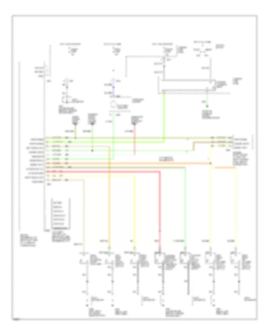
ANTI-THEFT
Anti-theft Wiring Diagram for Ford Probe GT 1993
 https://portal-diagnostov.com/license.html
Automotive Electricians Portal FZCO
Automotive Electricians Portal FZCO
https://portal-diagnostov.com/license.html
https://portal-diagnostov.com/license.html
Automotive Electricians Portal FZCO
Automotive Electricians Portal FZCO
List of elements for Anti-theft Wiring Diagram for Ford Probe GT 1993:
- 15a
- Acc
- Anti-theft control unit (behind left side of i/p, on central processing unit)
- Anti-theft indicator
- Armed signal
- Arming out
- Battery
- C2000
- C201
- C204
- C213
- C214
- C215
- C240
- C409
- Central processing unit (behind left side of i/p, rear of interior panel)
- Disarm input
- Engine fuse
- Exterior lights system (hazard lights)
- G106 (left front of vehicle, near fog light)
- G300 (below left front seat)
- G407 (lower center rear of luggage compartment)
- Ground
- Hazard lights
- Headlights
- Headlights system (headlight relay)
- Hood open
- Hood switch
- Hood switch (on engine compt latch assy)
- Horn
- Horn enable
- Horns system (horn relay)
- Hot at all times
- Hot in run or start
- Ignition
- Ignition switch
- Instrument cluster
- Interior fuse panel
- Joint connector
- Keyless entry module (in front of right quarter panel, behind quarter trim)
- Left door key cylinder switch (part of key cyl)
- Left door lk sw
- Left door lock switch (part of key cyl)
- Liftgate key cyl
- Liftgate key switch (right rear of luggage compt)
- Liftgate open
- Luggage compart- ment light switch (center of luggage compt)
- Meter fuse
- Nca
- Off
- Option #1
- Option #2
- Option sw
- Red
- Right door key cylinder switch (part of key cyl)
- Right door lk sw
- Right door lock switch (part of key cyl)
- Room fuse
- Run
- Start
- Start enable
- Starter interrupt relay
- Starting/ charging system (starter motor)
- With remote keyless entry
 Čeština
 Dansk
Dansk Deutsch
 Ελληνικά
 English
 English
 Español
 Suomi
Suomi Français
 Français
 עברית
עברית Hrvatski
 Magyar
 Italiano
 日本語
日本語 Nederlands
 Polski
 Português
 Português
 Română
 Русский
 Slovenčina
 Slovenščina
 Svenska
 Türkçe
 中文 (中国)
 한국어
한국어
