CRUISE CONTROL
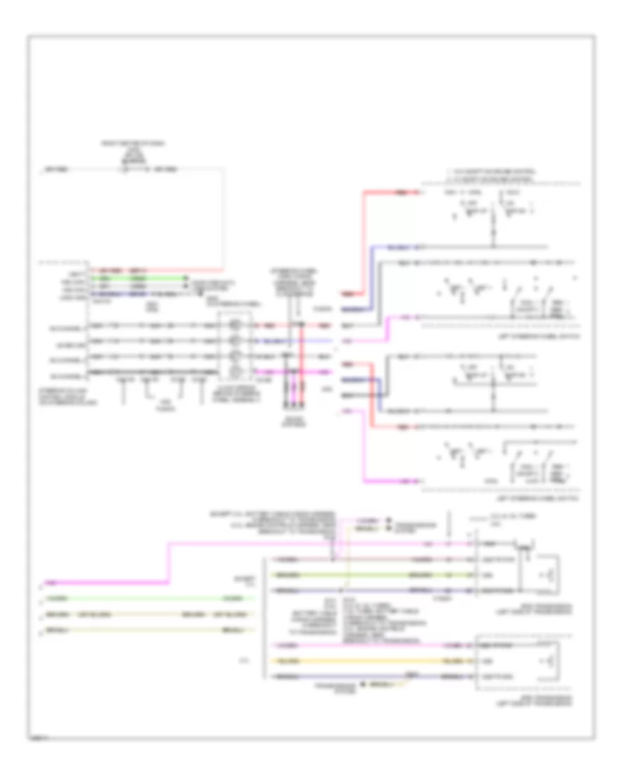
Cruise Control Wiring Diagram, Except Hybrid (1 of 2) for Ford Fusion SE 2013
 https://portal-diagnostov.com/license.html
Automotive Electricians Portal FZCO
Automotive Electricians Portal FZCO
https://portal-diagnostov.com/license.html
https://portal-diagnostov.com/license.html
Automotive Electricians Portal FZCO
Automotive Electricians Portal FZCO
List of elements for Cruise Control Wiring Diagram, Except Hybrid (1 of 2) for Ford Fusion SE 2013:
- (left front of engine compt) g101
- (not used)
- (or ret04)
- 1.6l
- 1.6l turbo
- 1.6l turbo a/t
- 2.0l
- 2.5l
- 3.7l
- A/t
- Accelerator pedal position sensor (left side of dash)
- App1
- App2
- Apprtn1
- Apprtn2
- Appvref1
- Appvref2
- Battery junction box (bjb) (left side of engine compt)
- Body control module (left end of dash)
- Bpp
- Bps
- C1035a
- C1035b
- C1232b
- C1232e
- C1381b
- C1381e
- C1551b
- C1551e
- C1551t
- C175b
- C175e
- C215
- C219
- C2280b
- C2280f
- C2280h
- Cbb23
- Ccb08
- Ce412
- Ce426
- Ces09
- Computer data lines system
- Electronic throttle control (etc) (2.0l & 2.5l:
- Etcref
- Etcrtn
- Except 1.6l turbo
- Except 3.7l
- Fuse 10a
- Fuse 15a
- Fuse 5a
- Fuse 7.5a
- G101 (left front of engine compt)
- G104 (right side of engine compt)
- Gd113
- Gd120
- Gnd
- Hot at all times
- Hot in start or run
- Hs can+
- Hs can-
- Hs1 can+
- Hs1 can-
- Hs2 can+
- Hs2 can-
- Le111
- Le134
- Le136
- Le137
- M/t
- Micro
- On throttle body)
- Oss
- Powertrain control module (pcm)
- Proximity warning radar unit (left front of engine compt)
- Pwr gnd
- Re134
- Re136
- Re137
- Ret24
- S204 (engine controls sensor harness, near breakout to coil on plug 3)
- S206 (fusion)
- S214
- S305
- Sbp32
- Stop lamp switch (under left side of dash)
- Tacm +
- Tacm -
- Tp1
- Tp2
- Trp
- Tss/oss/ tr gnd c175t
- Turbo
- Vbatt
- Vdb04
- Vdb05
- Vdb25
- Vdb26
- Ve701
- Ve702
- Ve818
- Ve819
- Vet26
- Vet32
- Vpwr
- Vref tss/oss/ tr vppwr
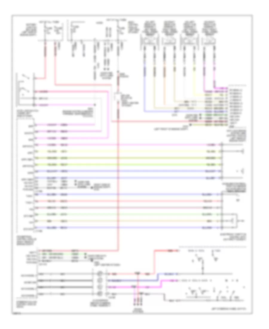
Cruise Control Wiring Diagram, Except Hybrid (2 of 2) for Ford Fusion SE 2013
 https://portal-diagnostov.com/license.html
Automotive Electricians Portal FZCO
Automotive Electricians Portal FZCO
https://portal-diagnostov.com/license.html
https://portal-diagnostov.com/license.html
Automotive Electricians Portal FZCO
Automotive Electricians Portal FZCOList of elements for Cruise Control Wiring Diagram, Except Hybrid (2 of 2) for Ford Fusion SE 2013:
- (2.0l & 1.6l turbo) (1.6l turbo: battery cable (battery cable
- (except 2.0l: battery cable wiring harness, in breakout to transmission) (2.0l: engine controls harness, near breakout to transmission) s142
- (right center of dash) (mkz) splice block 26
- (steering wheel horn wiring harness, near breakout to clockspring)
- 0ss vp pwr
- 2.0l & 1.6l turbo
- 2.5l
- 3.7l
- 6f35 transmission (left side of transmission)
- 6f50 transmission (left side of transmission)
- Ad channel 2
- Ad channel 3
- Ad channel 4
- Ad return
- C1520a
- C218b
- C218c
- C2414a
- C2414d
- Clock spring (behind steering wheel assembly)
- Cncl
- Computer data lines system
- Except 3.7l
- Fusion
- G200 (in steering wheel)
- Gap dn
- Gap up
- Gd124
- Hs2 can+
- Hs2 can-
- Left steering wheel switch
- Logic gnd
- Mkz
- Nca
- Off
- On/off
- Oss
- Oss/tr gnd
- Oss/tr pwr
- Red
- Res
- Res/ cncl
- S143
- S143 s141 (2.5l)
- S221 (mkz)
- S237
- S238
- S239
- Sbp13
- Set +
- Set -
- Sound systems
- Steering column control module (on steering column)
- To transmission)
- Tr-p
- Transmissions system
- Trs
- Vbatt
- Vdb25
- Vdb26
- W/ adaptive cruise control
- W/o adaptive cruise control
- Wiring harness, in breakout
- Wiring harness, in breakout to transmission) (2.0l: engine controls harness, near breakout to transmission)
Cruise Control Wiring Diagram, Hybrid for Ford Fusion SE 2013
 https://portal-diagnostov.com/license.html
Automotive Electricians Portal FZCO
Automotive Electricians Portal FZCO
https://portal-diagnostov.com/license.html
https://portal-diagnostov.com/license.html
Automotive Electricians Portal FZCO
Automotive Electricians Portal FZCOList of elements for Cruise Control Wiring Diagram, Hybrid for Ford Fusion SE 2013:
- (not used)
- (on left front hub assembly) left front wheel speed sensor
- (on left rear hub assembly) left rear wheel speed sensor
- (on right front hub assembly) right front wheel speed sensor
- (on right rear hub assembly) right rear wheel speed sensor
- (right side of engine compt) g105
- Accelerator pedal position sensor (on accelerator pedal bracket)
- Ad channel 2
- Ad channel 3
- Ad channel 4
- Ad return
- Anti-lock brake system (abs) control module (left rear of engine compt)
- App rtn1
- App rtn2
- App1
- App2
- Appv ref1
- Appv ref2
- Battery junction box (bjb) (left side of engine compt)
- Body control module (left end of dash)
- Bpp
- Bps
- C1010
- C1035a
- C175b
- C175e
- C2114a
- C215
- C218b
- C219
- C2280b
- C2280h
- Ccb08
- Ce412
- Ce426
- Ces09
- Clockspring (behind steering wheel assembly)
- Cncl
- Computer data lines system
- Electronic throttle control (etc) (on throttle body)
- Etc ref
- Etc rtn
- Fuse 10a
- Fuse 30a
- Fuse 5a
- Fuse 7.5a
- G102 (left front of engine compt)
- G200 (left center of dash)
- Gd113
- Gd121
- Gd124
- Gnd
- Hot at all times
- Hs can+
- Hs can-
- Hs1 can+
- Hs1 can-
- Hs2 can+
- Hs2 can-
- Le134
- Le136
- Le137
- Left steering wheel switch
- Lf sens hi
- Lf sens lo
- Lr sens hi
- Lr sens lo
- Micro
- Nca
- Off
- Powertrain control module (right rear of engine compt)
- Pwr gnd
- Rca17
- Rca18
- Rca19
- Rca20
- Re134
- Re136
- Re137
- Re406
- Red
- Res
- Rf sens hi
- Rf sens lo
- Rr sens hi
- Rr sens lo
- S204 (engine controls sensor harness, near breakout to c1010)
- S237
- S238
- S239
- Sbb69
- Sbp13
- Set +
- Set -
- Sig
- Sig rtn
- Sound systems
- Splice block 26 (mkz) (right center of dash)
- Steering column control module (sccm)
- Stop lamp switch (under left side of dash)
- Tacm +
- Tacm -
- Tp1
- Tp2
- Vbatt
- Vca03
- Vca04
- Vca05
- Vca06
- Vdb04
- Vdb05
- Vdb25
- Vdb26
- Ve701
- Ve702
- Ve818
- Ve819

 Čeština
 Dansk
Dansk Deutsch
 Ελληνικά
 English
 English
 Español
 Suomi
Suomi Français
 Français
 עברית
עברית Hrvatski
 Magyar
 Italiano
 日本語
日本語 Nederlands
 Polski
 Português
 Português
 Română
 Русский
 Slovenčina
 Slovenščina
 Svenska
 Türkçe
 中文 (中国)
