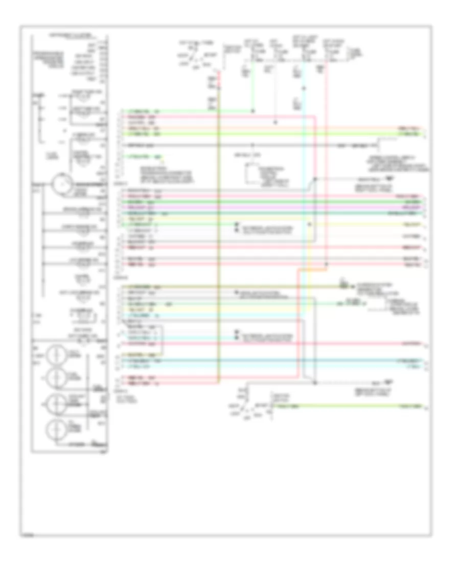
INSTRUMENT CLUSTER
Instrument Cluster Wiring Diagram (1 of 2) for Ford Bronco 1995
 https://portal-diagnostov.com/license.html
Automotive Electricians Portal FZCO
Automotive Electricians Portal FZCO
https://portal-diagnostov.com/license.html
https://portal-diagnostov.com/license.html
Automotive Electricians Portal FZCO
Automotive Electricians Portal FZCO
List of elements for Instrument Cluster Wiring Diagram (1 of 2) for Ford Bronco 1995:
- (behind bottom of left cowl panel)
- (behind bottom of right cowl panel)
- (behind lower center of i/p)
- (behind lower right side of i/p, below glove compt)
- (left side of engine compt,
- (left side of safety wall)
- (w/ tach) (w/o tach)
- 20 ohms
- 4x4 ind.
- 500 ohms
- A10
- A11
- A12
- A13
- A14
- A5 b6
- Acc
- Air bag ind.
- Amplifier assembly
- Anti-lock brake ind.
- Anti-theft ind.
- B10
- B12
- B13
- Bat
- Brake warning ind.
- Charge ind.
- Charging system (generator/ voltage regulator)
- Check engine ind.
- Chime module
- Conn a
- Conn b
- Conn c
- Control
- Coolant temp.
- Coolant temp. gauge
- Enable psom programming connector
- Engine speed
- Exterior lights system (multi-function switch)
- Fasten seat belt ind.
- Fuel gauge
- Fuel level
- Fuse 10a
- Fuse 15a
- Fuse 4a
- Fuse panel: i/p
- G200
- G203
- Gnd
- Headlights system (multi-function switch)
- Hi beam ind.
- Hot at all times
- Hot in run
- Hot in run or start
- Hot w/ light sw in head or park
- Ign
- Ign (run)
- Ignition switch
- Illum.
- Illum. lamps
- Instrument cluster
- Left turn ind.
- Lock
- Low range ind.
- Module
- Near brake master cylinder)
- Off
- Oil press.
- Oil press. gauge
- Powertrain
- Programmable speedometer/ odometer module
- Right turn ind.
- Run
- Speed control servo/
- Start
- Tacho- meter
- Test
- Volt- meter
- Vss input
- Vss output
- Vss return
- Warning
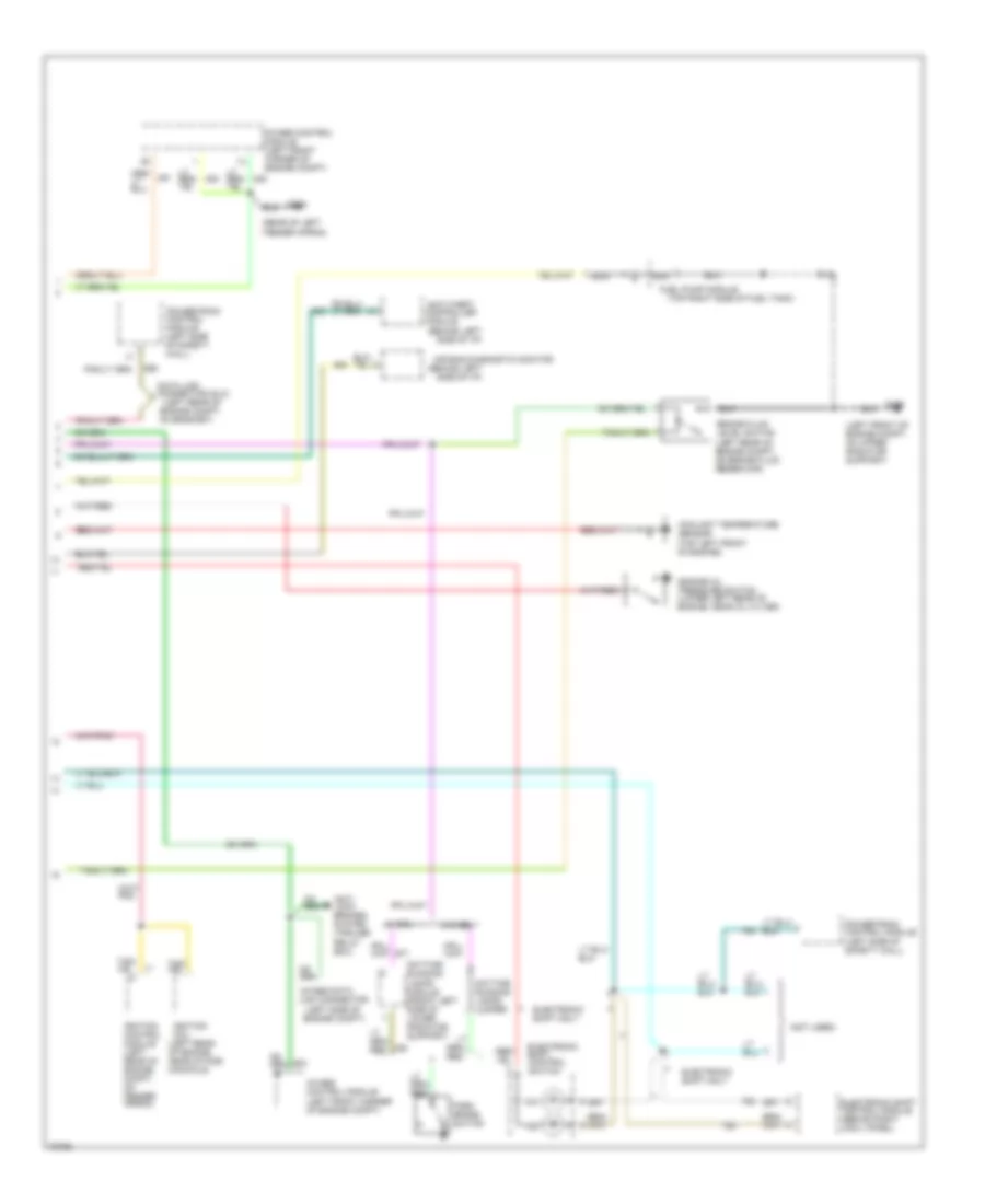
Instrument Cluster Wiring Diagram (2 of 2) for Ford Bronco 1995
 https://portal-diagnostov.com/license.html
Automotive Electricians Portal FZCO
Automotive Electricians Portal FZCO
https://portal-diagnostov.com/license.html
https://portal-diagnostov.com/license.html
Automotive Electricians Portal FZCO
Automotive Electricians Portal FZCOList of elements for Instrument Cluster Wiring Diagram (2 of 2) for Ford Bronco 1995:
- (behind left side of i/p)
- (left front of engine compt, on upper radiator support)
- (left rear of engine compt,
- (left rear of engine, near intake manifold)
- (left side of engine compt)
- (not used)
- (rear of left fender apron)
- (top left front of engine)
- (top right side of fuel tank)
- 4wabs control module (left front corner of engine compt)
- 4wabs data link connector
- 4x4
- Air bag diagnostic monitor
- Anti- lock brakes system (trailer relay box)
- Anti-theft controller
- Brake fluid level switch (left rear of engine compt, on brake fluid reservoir)
- Coolant temperature sensor
- Data link connector (dlc)
- Daytime running lamps jumper
- Daytime running lamps module (front left side of lower radiator support)
- Electronic shift control module (behind right cowl panel)
- Electronic shift control switch
- Electronic shift only
- Engine oil pressure switch (lower left rear of engine, near oil filter)
- Fuel pump module
- G104
- G108
- Ignition coil
- Ignition control module (left rear of engine compt, on fender apron)
- Module
- Nca
- On bracket)
- Park brake switch
- Powertrain control module (left side of safety wall)
- Powertrain control module (left side of safety wall)
- W/ drl
- W/o drl
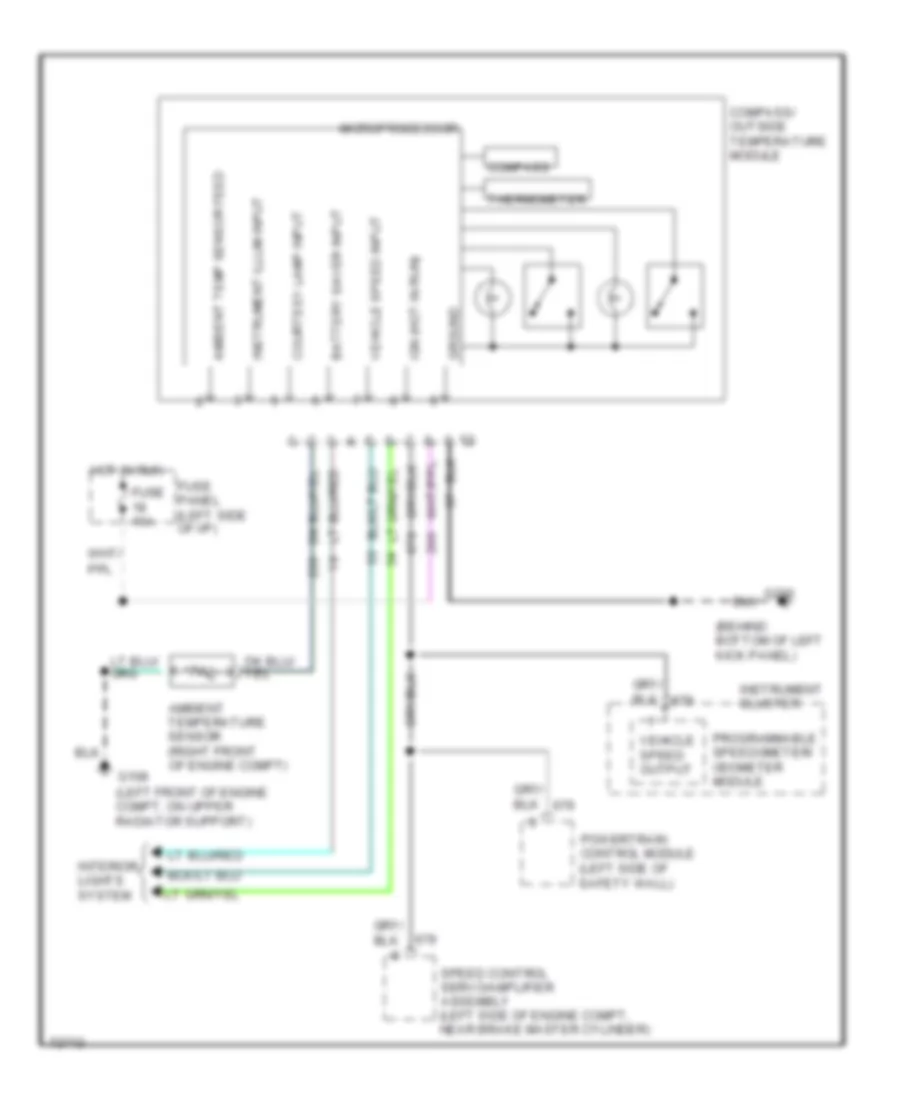
Overhead Console Wiring Diagram for Ford Bronco 1995
 https://portal-diagnostov.com/license.html
Automotive Electricians Portal FZCO
Automotive Electricians Portal FZCO
https://portal-diagnostov.com/license.html
https://portal-diagnostov.com/license.html
Automotive Electricians Portal FZCO
Automotive Electricians Portal FZCOList of elements for Overhead Console Wiring Diagram for Ford Bronco 1995:
- (behind bottom of left kick panel)
- (left front of engine compt, on upper radiator support)
- Ambient temp sensor feed
- Ambient temperature sensor (right front of engine compt)
- Battery saver input
- Compass
- Compass/ outside temperature module
- Courtesy lamp input
- Fuse 10a
- Fuse panel (left side of i/p)
- G108
- G200
- Ground
- Hot in run
- Ign (hot in run)
- Instrument cluster
- Instrument illum input
- Interior lights system
- Microprocessor
- Powertrain control module (left side of safety wall)
- Programmable speedometer/ odometer module
- Speed control servo/amplifier assembly (left side of engine compt, near brake master cylinder)
- Thermometer
- Vehicle speed input
- Vehicle speed output

 Čeština
 Dansk
Dansk Deutsch
 Ελληνικά
 English
 English
 Español
 Suomi
Suomi Français
 Français
 עברית
עברית Hrvatski
 Magyar
 Italiano
 日本語
日本語 Nederlands
 Polski
 Português
 Português
 Română
 Русский
 Slovenčina
 Slovenščina
 Svenska
 Türkçe
 中文 (中国)
