POWER DISTRIBUTION
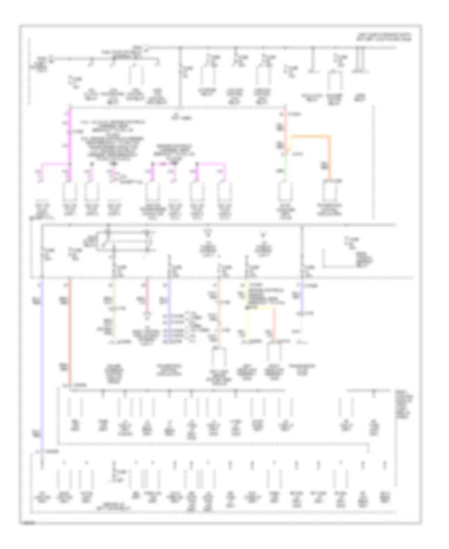
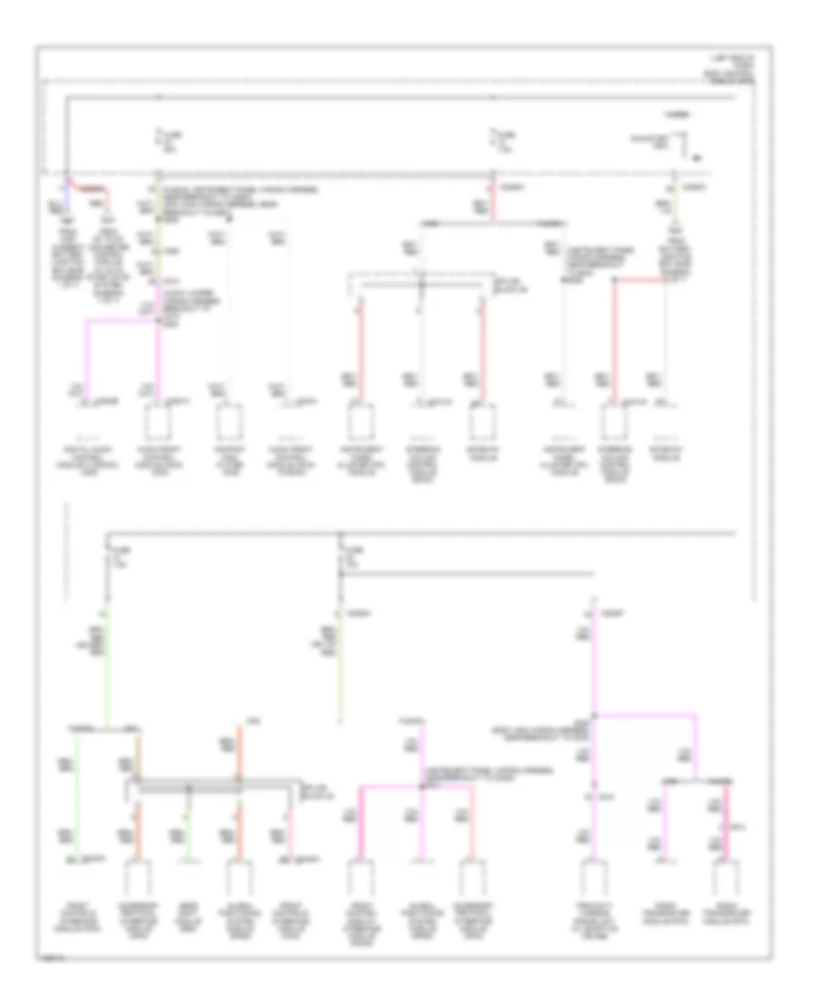
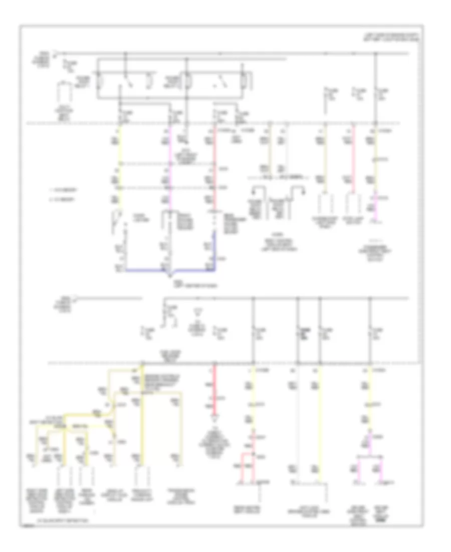
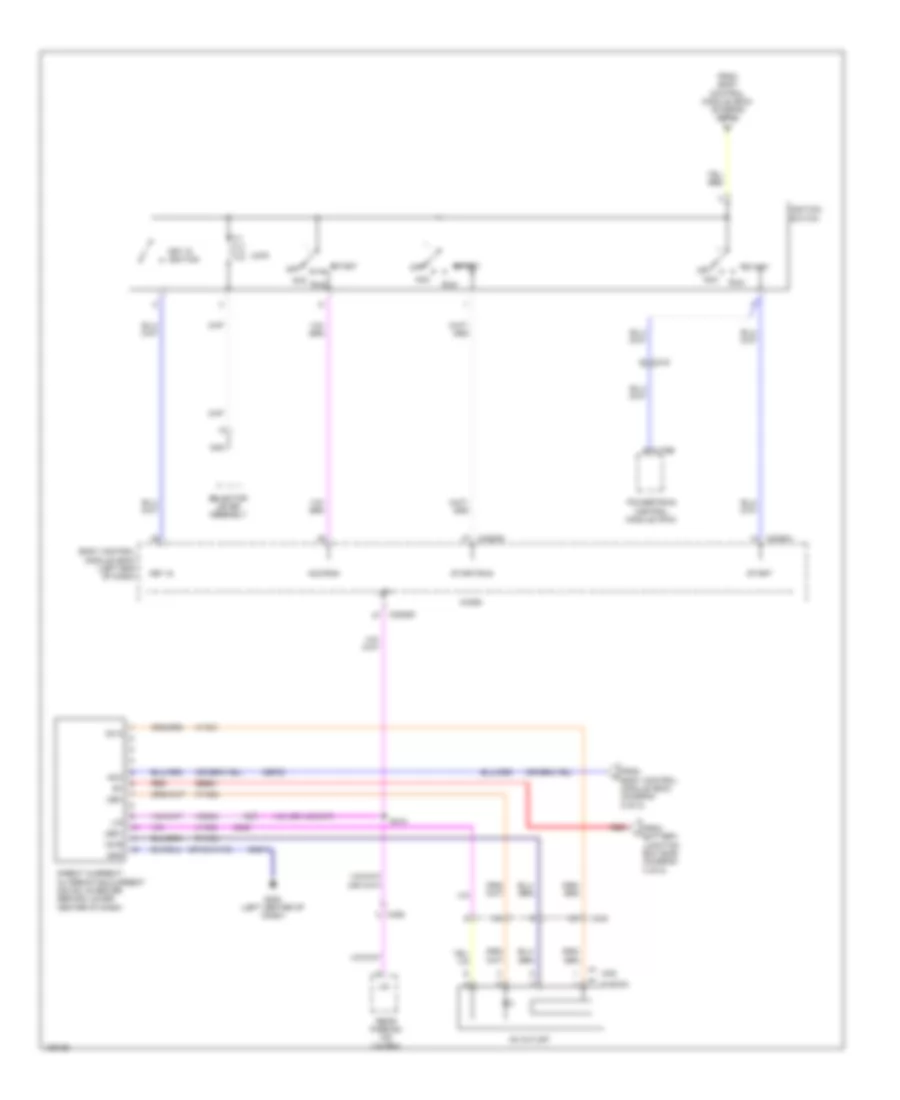
Power Distribution Wiring Diagram, Except Hybrid (1 of 7) for Ford Fusion Titanium 2014
 https://portal-diagnostov.com/license.html
Automotive Electricians Portal FZCO
Automotive Electricians Portal FZCO
https://portal-diagnostov.com/license.html
https://portal-diagnostov.com/license.html
Automotive Electricians Portal FZCO
Automotive Electricians Portal FZCO
List of elements for Power Distribution Wiring Diagram, Except Hybrid (1 of 7) for Ford Fusion Titanium 2014:
- (1.5l & 2.0l: engine controls harness, near breakout to coil on plug 1) (1.6l: engine control wiring harness, near breakout to knock sensor 2) (2.5l: engine controls harness, near breakout to fuel injector 2) (3.7l: engine controls harness, near breakout to coil on plug 3)
- (engine controls sensor harness, near breakout to c134)
- (engine controls sensor harness, near breakout to g101)
- (engine controls sensor harness, near breakout to g101) s112
- (except 1.5l: engine controls harness, near breakout to crankshaft position sensor) (1.5l: engine controls harness, near breakout to variable camshaft timing 11 solenoid)
- (left side of engine compt) battery junction box (bjb)
- (not used)
- 1.5l & 1.6l turbo
- 1.5l turbo
- 1.6l turbo
- 1.6l turbo & 2.5l
- 2.0l turbo
- 2.5l
- 2.5l, 1.6l & 1.5l turbo
- 3.7l
- 3.7l & 2.0l turbo
- 3.7l & 2.5l)
- 3.7l, 2.0l turbo & 1.5l turbo
- Active grille shutter
- Air conditioning (a/c) compressor control solenoid
- Battery
- Battery monitoring sensor (w/ auto start/stop system)
- C1010
- C1026
- C102c
- C1035a
- C1035c
- C1232b
- C134
- C1381b
- C146
- C1463a
- C1551b
- C1558c
- C1617a
- C1617b
- C1617c
- C1617e
- C1617f
- C1617h
- C1716a red
- C1716b
- C1716c
- C1716e
- C1716f
- C1716h
- C175b
- C19151b
- C1915b
- Cabin heater coolant pump (w/ auto start/ stop system)
- Charger cooler (cac) pump (1.5l)
- Egr stepper motor (2.5l)
- Engine coolant valve (1.6l turbo)
- Engine cooling bypass solenoid (1.6l turbo)
- Evap canister vent valve (except
- Evap vapor blocking valve (except 2.5l & 3.7l)
- Evaporative emission (evap) purge valve
- Except 2.5l & 3.7l
- Fuel pump (fp) relay
- Fuse 10a
- Fuse 15a
- Fuse 20a
- Generator
- Generator current sensor
- Heated oxygen sensor (ho2s) 12 (3.7l)
- Heated oxygen sensor (ho2s) 22 (3.7l)
- High current battery junction box (bjb) (left side of engine compt)
- Mass air flow intake air temperature (maf/iat) sensor (2.5l & 3.7l)
- Mega fuse 125a
- Mega fuse 50a
- Mega fuse 70a
- Mega fuse 8 275a (mkz) 200a (fusion)
- Nca
- Near breakout to g109)
- Pcm power relay
- Power steering control module (pscm)
- Powertrain control module (pcm)
- Red
- S110
- S113
- S147
- S151
- S315 (except 3.7 & 2.5l)
- Starter motor
- To body control module (bcm) (diagram 4 of 7)
- To body control module (bcm) (diagram 6 of 7)
- To dc to dc converter control module (diagram 7 of 7)
- To fuse 11 (diagram 2 of 7)
- To fuse 37 (diagram 2 of 7)
- Turbo- charger (tc) wastegate regulating solenoid valve (1.5l turbo, 1.6l turbo & 2.0l turbo)
- Turbo- charger bypass valve (tcby) (1.6l turbo, 2.0l turbo & 1.5l turbo)
- Universal heated oxygen sensor (ho2s) 11
- Universal heated oxygen sensor (ho2s) 11 (2.5l)
- Universal heated oxygen sensor (ho2s) 11 (3.7l)
- Universal heated oxygen sensor (ho2s) 21 (3.7l)
- Variable camshaft timing 11 (vct11) solenoid
- Variable camshaft timing 12 (vct12) solenoid
- Variable camshaft timing 21 (vct21) solenoid (3.7l)
- Variable camshaft timing 22 (vct22) solenoid (3.7l)
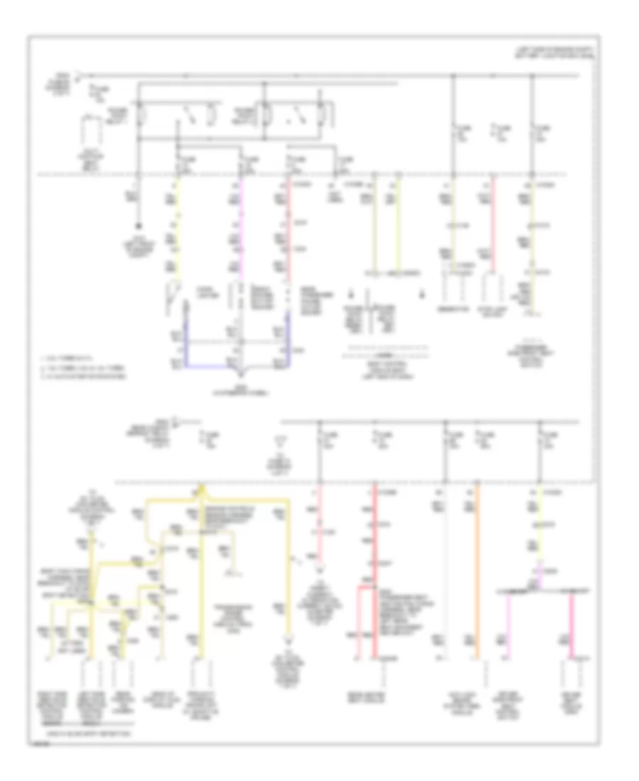
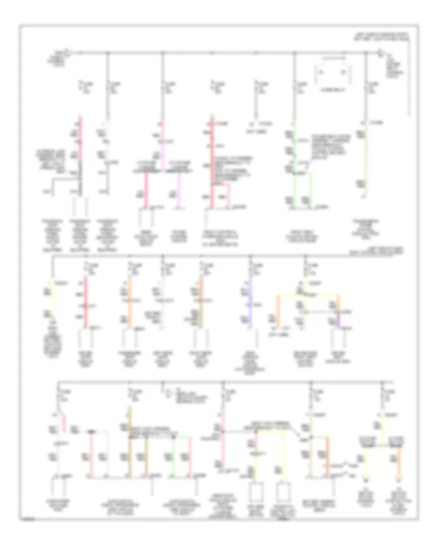
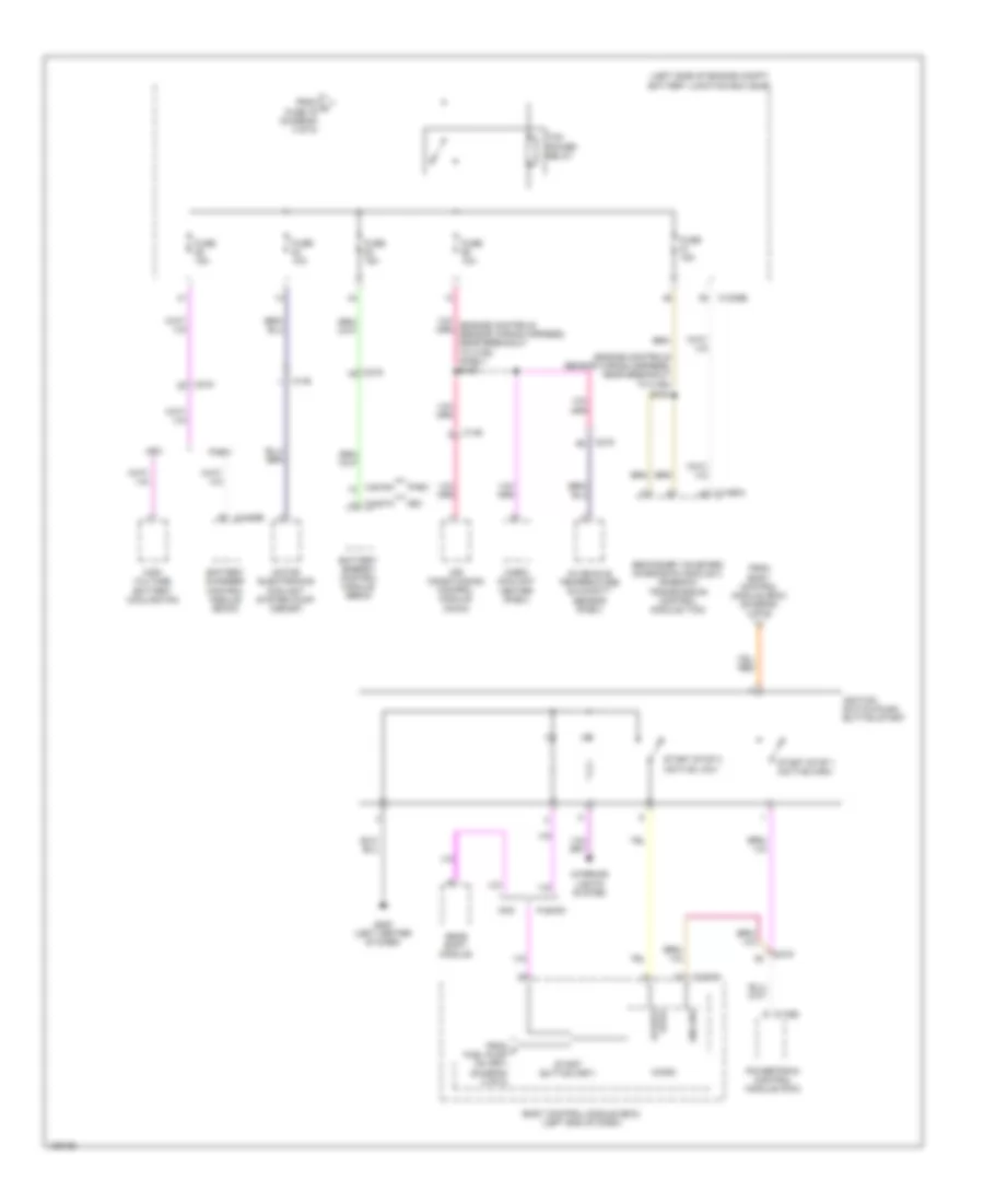
Power Distribution Wiring Diagram, Except Hybrid (2 of 7) for Ford Fusion Titanium 2014
 https://portal-diagnostov.com/license.html
Automotive Electricians Portal FZCO
Automotive Electricians Portal FZCO
https://portal-diagnostov.com/license.html
https://portal-diagnostov.com/license.html
Automotive Electricians Portal FZCO
Automotive Electricians Portal FZCOList of elements for Power Distribution Wiring Diagram, Except Hybrid (2 of 7) for Ford Fusion Titanium 2014:
- (1.5l, 1.6l & 2.0l: engine controls harness, near breakout to coil on plug 2) (2.5l: engine controls harness, near breakout to ignition transformer capacitor) (3.7l: engine controls harness, near breakout to coil on plug 3) s144
- (engine controls harness, near breakout to coil on plug 56) s154
- (left side of engine compt) battery junction box (bjb)
- (not used)
- 1.5l turbo
- 2.0l turbo 1.6l turbo
- 2.5l
- 3.7l
- A/c clutch relay
- Anti-lock brake system (abs) module
- Auto park ind (fet)
- Back lighting (fet)
- Blower motor relay
- Body control module (bcm) (left end of dash)
- Bsi (fet)
- C1010
- C1026
- C1035a
- C1035b
- C1232b
- C1381b
- C146
- C1463b
- C1509a
- C1510a
- C1551b
- C175b
- C1915b
- C192
- C2280b
- Coil on plug (cop) 1
- Coil on plug (cop) 2
- Coil on plug (cop) 3
- Coil on plug (cop) 4 (3.7l)
- Coil on plug (cop) 4 (except 3.7l)
- Coil on plug (cop) 5 (3.7l)
- Coil on plug (cop) 6 (3.7l)
- Demand lp/ batt save relay
- Evap canister vent valve
- Except 2.5l
- Fan control (fc) relay
- From e fuel pump (fp) relay (diagram 1 of 7)
- From fuse 7 (diagram 1 of 7)
- Fuse 10a
- Fuse 15a
- Fuse 30a
- Fuse 40a
- Fuse 50a
- Fuse 5a
- High fan control (hfc) relay
- Horn relay
- Ignition transformer capacitor (2.5l)
- Int lighting (fet)
- Left headlamp assembly (mkz)
- Lf drl lp (fet) (mkz)
- Lf fog lp (fet) (fusion)
- Lf hi beam (fet)
- Lf low beam (fet)
- Lf pos lp (fet) (mkz)
- Lf turn lp (fet) (mkz)
- Low fan control (lfc) relay
- Lr stop pos lps (fet)
- Lr turn lp (fet)
- Park aid ind (fet)
- Park lps (fet)
- Pcm wake up (fet)
- Power steering control module (pscm)
- Powertrain control module (pcm)
- Rear window defrost relay
- Rev lps (fet)
- Rf drl lp (fet) (mkz)
- Rf fog lp (fet)
- Rf hi beam (fet)
- Rf low beam (fet)
- Rf pos lp (fet) (mkz)
- Rf turn lamp (fet)
- Rf turn lp (fet)
- Right headlamp assembly (mkz)
- Rr stop pos lps (fet)
- Rr turn lp (fet)
- Run/ start relay
- Starter relay
- Stop/ chmsl (fet)
- To body control module (bcm) (diagram 6 of 7)
- To fuse 23 (diagram 3 of 7)
- To fuse 53 (diagram 3 of 7)
- Transmission fluid pump
- White light (fet)
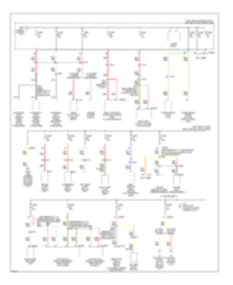
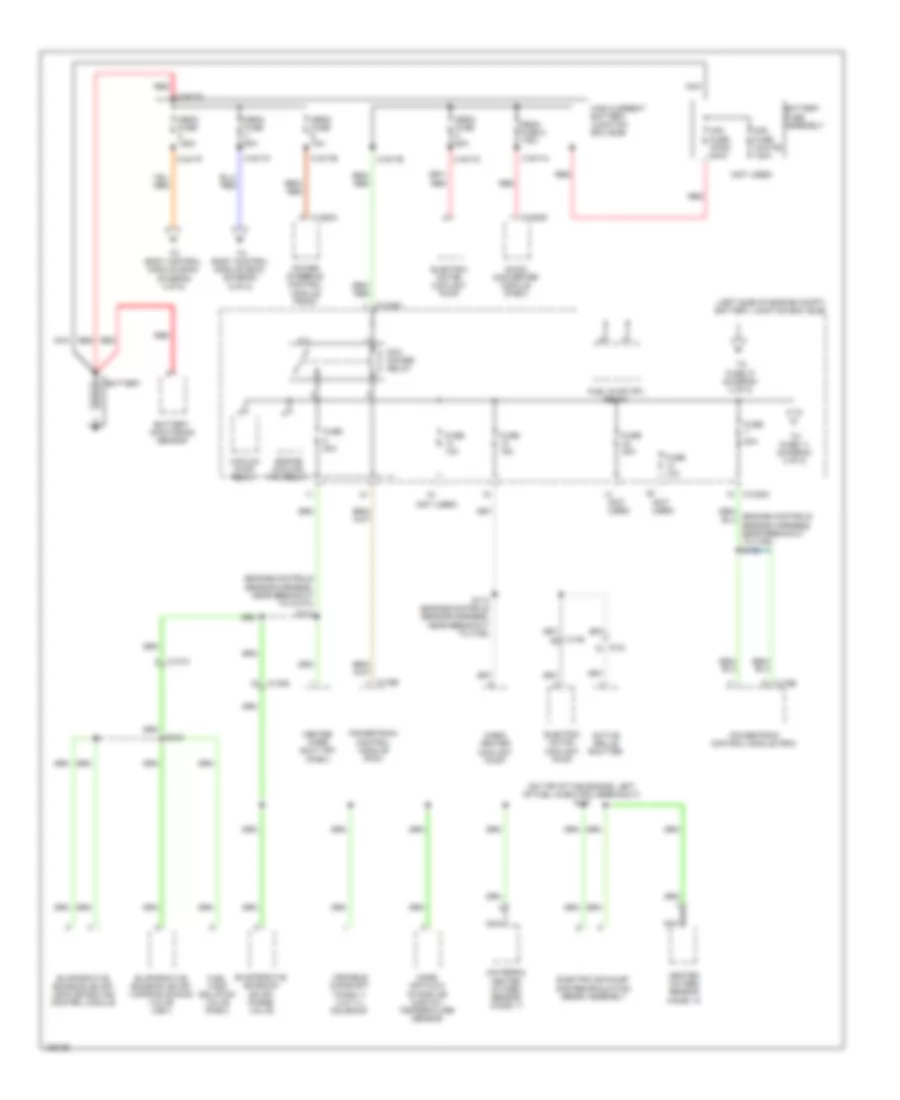
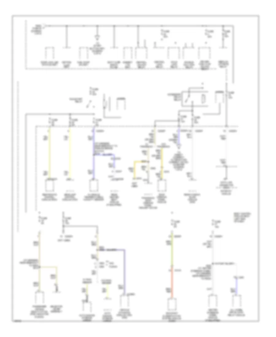
Power Distribution Wiring Diagram, Except Hybrid (3 of 7) for Ford Fusion Titanium 2014
 https://portal-diagnostov.com/license.html
Automotive Electricians Portal FZCO
Automotive Electricians Portal FZCO
https://portal-diagnostov.com/license.html
https://portal-diagnostov.com/license.html
Automotive Electricians Portal FZCO
Automotive Electricians Portal FZCOList of elements for Power Distribution Wiring Diagram, Except Hybrid (3 of 7) for Ford Fusion Titanium 2014:
- (body main wiring harness, near breakout to c275) (w/ blind spot detection) s308
- (left end of dash)
- (left side of engine compt) battery junction box (bjb)
- (mkz w/ blind spot detection)
- (not used)
- 1.6l turbo, 2.5l & 1.5l turbo
- 2.0l turbo & 3.7l
- Anti-lock brake system (abs) module
- Body control module (bcm)
- C1010
- C102a
- C1035a
- C1035b
- C129
- C146
- C1558a
- C215
- C219
- C2280c
- C263
- C3047
- C3053
- C3133
- C3304b
- C340
- C341a
- C406
- C922
- Cigar lighter
- Driver seat module (dsm)
- Driver side front seat control switch
- From fuse 68 (diagram 2 of 7)
- From rear window defrost relay (diagram 2 of 7)
- Front power outlet socket
- Fuse 10a
- Fuse 15a
- Fuse 20a
- Fuse 30a
- Fuse 40a
- Fuse 60a
- G101 (left front of engine compt)
- G200 (in steering wheel)
- Generator
- Head up display (hud) module
- Left side obstacle detection control module (sod-l)
- Micro
- Multi contour seat relay
- Passenger side front seat control switch
- Power point relay 1
- Power point relay 2
- Power point relay reset (fet)
- Power point relay set (fet)
- Proximity warning radar unit (w/ adaptive cruise)
- Rear heated seat module
- Rear parking aid camera
- Rear passenger power outlet socket
- Red
- Right side obstacle detection control module (sod-r)
- S302 (passenger seat heating pad wiring harness, near breakout to left rear seat backrest heater mat)
- S316
- Sensor harness, near breakout to g101) s114
- Stop lamp switch
- To dc to dc converter control module (diagram 7 of 7)
- To dc to dc converter module control (diagram 7 of 7)
- To direct current/ alternating current (dc/ac) inverter (diagram 7 of 7)
- To fuse 72 (diagram 4 of 7)
- Transmission range control module (trcm) (mkz)
- W/ auto start/stop system
- W/ memory
- W/o memory
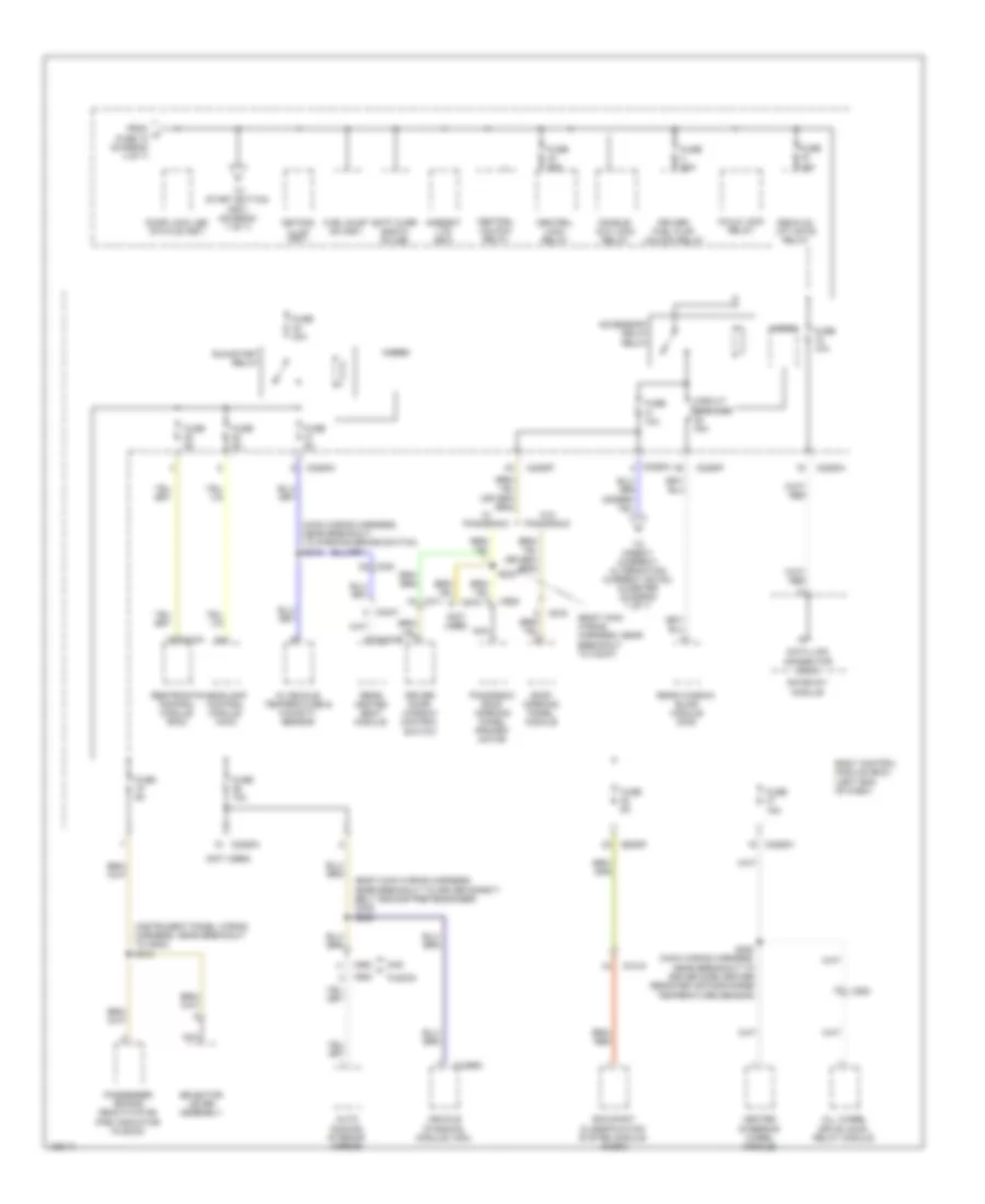
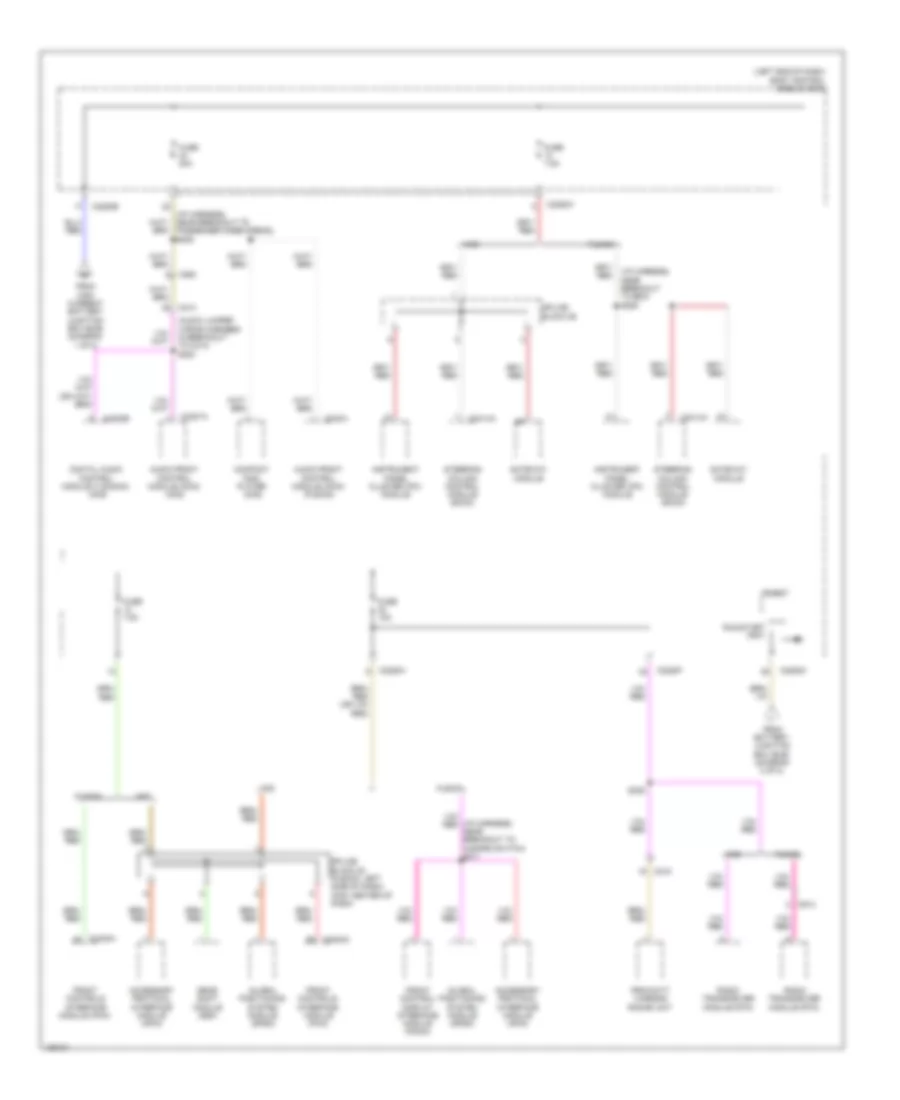
Power Distribution Wiring Diagram, Except Hybrid (4 of 7) for Ford Fusion Titanium 2014
 https://portal-diagnostov.com/license.html
Automotive Electricians Portal FZCO
Automotive Electricians Portal FZCO
https://portal-diagnostov.com/license.html
https://portal-diagnostov.com/license.html
Automotive Electricians Portal FZCO
Automotive Electricians Portal FZCOList of elements for Power Distribution Wiring Diagram, Except Hybrid (4 of 7) for Ford Fusion Titanium 2014:
- (left end of dash) body control module (bcm)
- (left side of engine compt) battery junction box (bjb)
- (near breakout to driver side seat cushion blower motor) (w/ heated seats) s227
- (near breakout to passenger safety belt anchor pretensioner) s306
- (not used)
- A16
- Audio digital signal processing (dsp) module (thx audio)
- Audio digital signal processing (dsp) module (w/ sony)
- B3 c311
- C1010
- C1035b
- C146
- C214
- C215
- C219
- C2280a
- C2280f
- C2280h
- C2402b
- C3052
- C311
- C312
- C313
- C3133
- C314
- C3265a
- C341b
- C4174a
- C4326b
- C4452c
- C466a
- C501a
- C652a
- C919
- C925
- Driver door module (ddm)
- Driver safety belt anchor pretensioner)
- Driver seat module (dsm)
- Driver side front seat control switch
- From fuse 81 (diagram 3 of 7)
- From high current battery junction box (bjb) (diagram 1 of 7)
- Front controls interface module (fcim) (w/ heated seats)
- Front seat climate control module (scme)
- Fuse 20a
- Fuse 30a
- Fuse 5a
- Fuse 7.5a
- Keyless entry keypad
- Left rear door module (rdm)
- Nca
- Panoramic roof opening panel primary motor (if equipped)
- Panoramic roof opening panel secondary motor (if equipped)
- Panoramic roof opening panel shield motor (if equipped)
- Passenger door module (pdm)
- Power striker module
- Rear gate trunk module (rgtm)
- Rear gate trunk module (rgtm) (w/ power luggage compartment)
- Red
- Right rear door module (rdm)
- Roof opening panel module (w/o panoromic roof)
- S210 (near breakout to g201)
- S318 (near breakout to driver safety belt anchor pretensioner)
- S327 (near breakout to front seat climate control module)
- S411
- S902 (near breakout to left vanity mirror lamp)
- Subwoofer amplifier (mkz)
- To door lock led status (fet) (diagram 5 of 7)
- To ignition switch (diagram 7 of 7)
- To push button start ignition switch (diagram 7 of 7)
- Transmission fluid pump
- Transmission range control module (trcm) (mkz)
- W/ heated seats
- W/ power luggage compartment
- W/ push button start
- W/o power luggage compartment
- W/o push button start
- Wiper relay
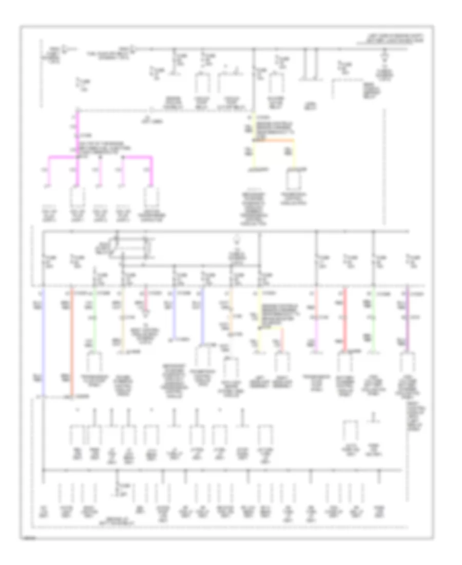
Power Distribution Wiring Diagram, Except Hybrid (5 of 7) for Ford Fusion Titanium 2014
 https://portal-diagnostov.com/license.html
Automotive Electricians Portal FZCO
Automotive Electricians Portal FZCO
https://portal-diagnostov.com/license.html
https://portal-diagnostov.com/license.html
Automotive Electricians Portal FZCO
Automotive Electricians Portal FZCOList of elements for Power Distribution Wiring Diagram, Except Hybrid (5 of 7) for Ford Fusion Titanium 2014:
- (body main wiring harness, near breakout to c3047)
- (body main wiring harness, near breakout to driver safety belt anchor pretensioner) (mkz) s323
- (instrument panel wiring harness, near breakout to g202) s212
- (main wiring harness, near breakout to parking brake switch) s219
- (not used)
- Accessory delay relay
- All wheel drive (awd) relay module
- Ambient ltg (fet)
- Auto dimming interior mirror
- Batt curr sns 5v fd (hb)
- Body control module (bcm) (left end of dash)
- C2280f
- C2280h
- C248
- C263
- C3047
- C310a
- C311
- C3133
- C3304b
- C4396c
- C900
- C919
- C925
- Central lock relay
- Central unlock relay
- Child lock relay
- Circuit breaker 30a
- Data link c0nnector (dlc)
- Decklid/ lift gate relay
- Door lock led status (fet)
- Double/ aux lock relay
- Driver door window control switch
- Driver/ fuel flap unlock relay
- From k fuse 18 (diagram 4 of 7)
- Fuel pump on (fet)
- Fuse 10a
- Fuse 15a
- Fuse 20a
- Fuse 30a
- Fuse 5a
- Fusion
- Gateway module
- Headlamp control module (hcm)
- Heated steering wheel module
- In vehicle temperature & humidity sensor
- Keypad illum (fet)
- Micro
- Mkz
- Nca
- Occupant classification system module (ocsm)
- Panoramic roof opening panel primary motor
- Passenger air bag deactivation (pad) indicator (fusion)
- Rear heated seat module
- Rear window blind module (mkz)
- Restraints control module (rcm)
- Roof opening panel module
- Run/start relay
- S220 (main wiring harness, near breakout to driver side center register air discharge temperature sensor)
- S233
- Selector lever assembly
- To direct current/ alternating current (dc/ac) inverter (diagram 7 of 7)
- To start button (fet) (diagram 7 of 7)
- Vehicle dynamics module (vdm)
- W/ panoramic
- W/o panoramic
Power Distribution Wiring Diagram, Except Hybrid (6 of 7) for Ford Fusion Titanium 2014
 https://portal-diagnostov.com/license.html
Automotive Electricians Portal FZCO
Automotive Electricians Portal FZCO
https://portal-diagnostov.com/license.html
https://portal-diagnostov.com/license.html
Automotive Electricians Portal FZCO
Automotive Electricians Portal FZCOList of elements for Power Distribution Wiring Diagram, Except Hybrid (6 of 7) for Ford Fusion Titanium 2014:
- (audio jumper wiring harness breakout to c214) s200
- (fusion: instrument panel wiring harness, near breakout to c2607) (mkz: main wiring harness, near breakout to c2607) s209
- (instrument panel wiring harness, near breakout to bcm) s206
- (instrument panel wiring harness, near breakout to c2480) s211
- (left end of dash) body control module (bcm)
- Accessory protocol interface module (apim)
- Audio front control module (acim) (fusion)
- Audio front control module (acim) (mkz)
- C214
- C215
- C2280b
- C2280c
- C2280f
- C2280h
- C2402a
- C240a
- C2414a
- C263
- C4820b
- C4821a
- C913
- Compact disc player (mkz)
- Digital audio control module c (dacmc) (mkz)
- From battery junction box (bjb) (diagram 2 of 7)
- From dc to dc converter control module (w/ auto start stop system) (diagram 7 of 7)
- From high current battery junction box (bjb) (diagram 1 of 7)
- Front control/ display interface module (fcdim)
- Front controls interface module (fcim)
- Fuse 10a
- Fuse 20a
- Fuse 7.5a
- Fusion
- Gateway module
- Gear shift module (gsm)
- Global positioning system module (gpsm)
- Instrument panel cluster (ipc) module
- Micro
- Mkz
- Proximity warning radar unit (w/ adaptive cruise)
- Radio transceiver module (rtm)
- Red
- Run/start (fet)
- S305 (body main wiring harness, near breakout to c300)
- Splice block 22
- Splice block 26
- Steering column control module (sccm)
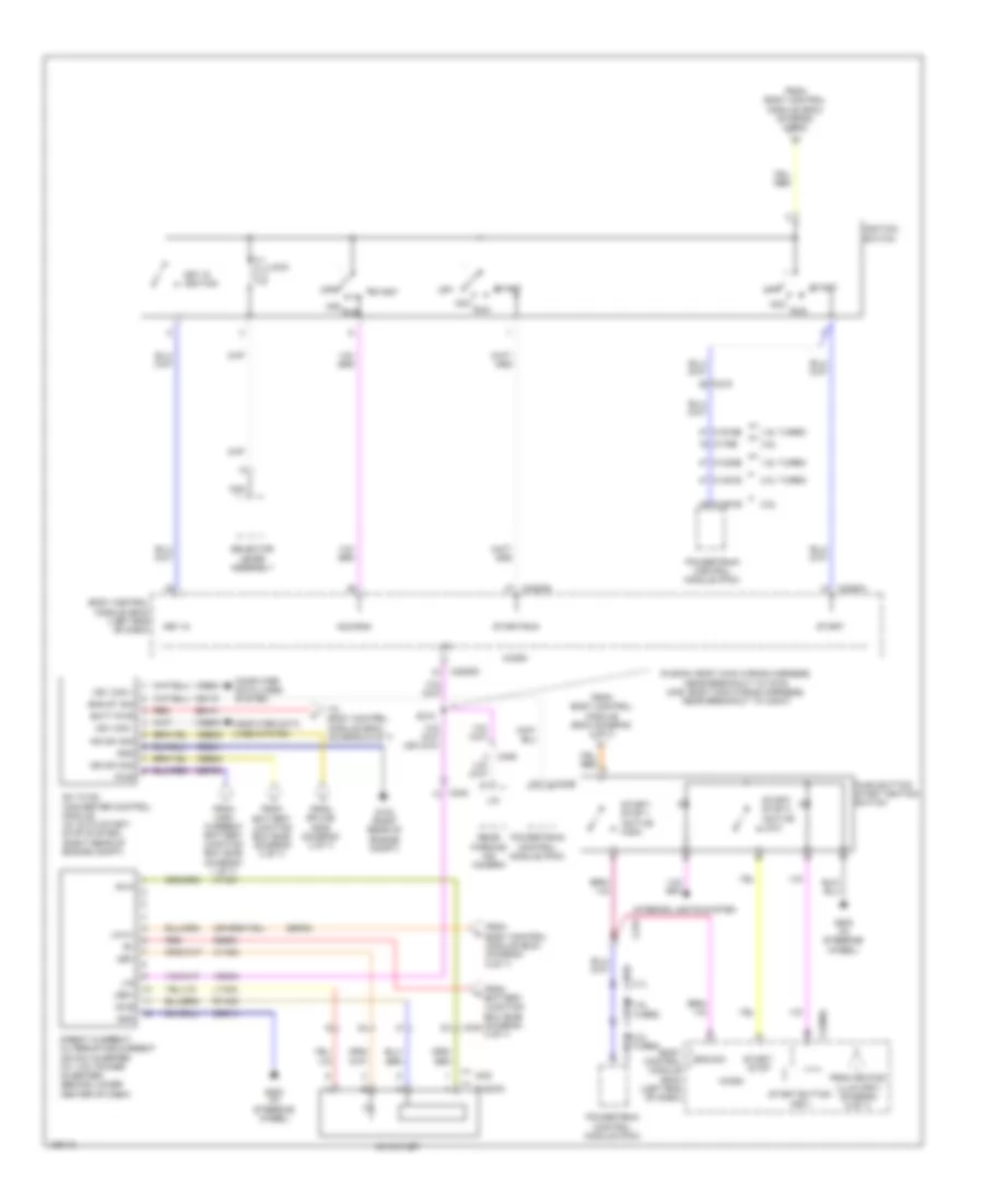
Power Distribution Wiring Diagram, Except Hybrid (7 of 7) for Ford Fusion Titanium 2014
 https://portal-diagnostov.com/license.html
Automotive Electricians Portal FZCO
Automotive Electricians Portal FZCO
https://portal-diagnostov.com/license.html
https://portal-diagnostov.com/license.html
Automotive Electricians Portal FZCO
Automotive Electricians Portal FZCOList of elements for Power Distribution Wiring Diagram, Except Hybrid (7 of 7) for Ford Fusion Titanium 2014:
- (fusion: body main wiring harness, near breakout to c275) (mkz: body main wiring harness, near breakout to c3047)
- 1.5l turbo
- 1.6l turbo
- 2.0l turbo
- 2.5l
- 3.5l
- 3.7l
- Ac outlet
- Ac-a
- Ac-b
- Acc
- Acc/run
- Batt pwr
- Battery junction box (bjb) (diagram 3 of 7)
- Body control module (bcm) (left end of dash)
- C1232b
- C1381b
- C1551b
- C175b
- C1915b
- C219
- C2280d
- C2280g
- C2280h
- C248
- C406
- Cbb23
- Ce170
- Computer data lines system
- Dc to dc converter control module (w/ auto start/ stop system) (right rear of engine compt)
- Direct current/ alternating current (dc/ac) inverter (w/ 110v power inverter) (behind lower center of dash)
- Eng st sig
- Eng sw
- From
- From battery junction box (bjb) (diagram c340 3 of 7)
- From body control module (bcm) (diagram 4 of 7)
- From body control module (bcm) (diagram 5 of 7)
- From high current battery junction box (bjb) (diagram 1 of 7)
- From keypad illum (fet) (diagram 5 of 7)
- From splice s308 (diagram 3 of 7)
- Fusion
- G103 (right rear of engine compt)
- G200 (in steering wheel)
- Gd214
- Gd241
- Gnd
- Hs1 can +
- Hs1 can -
- Hya01
- Hya02
- Ign sw sig
- Ignition switch
- Inn sw sig
- Interior lights system
- Key in
- Key in ignition
- Led+
- Led-
- Lin
- Lin 01
- Lock
- Lya03
- Micro
- Mkz
- Nca
- Off
- Powertrain control module (pcm)
- Push button start ignition switch
- Pwr
- Rear parking aid camera
- Red
- Run
- Rya03
- S310
- Sb101
- Sbb81
- Sbf03
- Sbp23
- Selector lever assembly
- Start
- Start button (fet)
- Start/ stop
- Start/ stop 1 (active high)
- Start/ stop 2 (active low)
- Start/run
- To body control module (bcm) (diagram 6 of 7)
- Vdb04
- Vdb05
- Vdn04
Power Distribution Wiring Diagram, Hybrid (1 of 8) for Ford Fusion Titanium 2014
 https://portal-diagnostov.com/license.html
Automotive Electricians Portal FZCO
Automotive Electricians Portal FZCO
https://portal-diagnostov.com/license.html
https://portal-diagnostov.com/license.html
Automotive Electricians Portal FZCO
Automotive Electricians Portal FZCOList of elements for Power Distribution Wiring Diagram, Hybrid (1 of 8) for Ford Fusion Titanium 2014:
- (engine controls sensor harness, near breakout to g1010)
- (left side of engine compt) battery junction box (bjb)
- (not used)
- (on top of the engine, left of fuel injector 4 breakout) s147
- Active grille shutter
- Battery
- Battery fuse assembly
- Battery monitoring sensor
- C1010
- C1026
- C1035a
- C1035c
- C134
- C146
- C1463a
- C1617a
- C1617b
- C1617c
- C1617e
- C1617f
- C1617h
- C1617k
- C175b
- C4453d
- Cabin heater coolant pump
- Dc/dc converter module (phev)
- Electric exhaust gas recirculation (eegr) assembly
- Electric motor coolant pump
- Engine cooling fan relay
- Evaporative emission (evap) leak detection control module
- Evaporative emission (evap) purge valve
- Evaporative emission (evap) vapor blocking valve (hev)
- Fuel pump (fp) relay
- Fuel tank isolation valve (phev)
- Fuse 10a
- Fuse 15a
- Fuse 20a
- Heated oxygen sensor (ho2s) 12
- Heater core shut off (phev)
- High current battery junction box (bjb)
- Mass air flow/ intake air (maf/iat) temperature sensor
- Mega fuse 125a
- Mega fuse 50a
- Mega fuse 70a
- Mega fuse 8 175a
- Midi fuse (pink) 200a
- Midi fuse (white) 120a
- Nca
- Pcm power relay
- Power steering control module (pscm)
- Powertrain control module (pcm)
- Red
- S110 (engine controls sensor harness, near breakout to c192)
- S113
- S315
- To body control module (bcm) (diagram 4 of 8)
- To body control module (bcm) (diagram 6 of 8)
- To fuse 11 (diagram 2 of 8)
- To fuse 37 (diagram 2 of 8)
- Universal heated oxygen sensor (ho2s) 11
- Vacuum pump relay
- Variable camshaft timing 11 (vct11) solenoid
Power Distribution Wiring Diagram, Hybrid (2 of 8) for Ford Fusion Titanium 2014
 https://portal-diagnostov.com/license.html
Automotive Electricians Portal FZCO
Automotive Electricians Portal FZCO
https://portal-diagnostov.com/license.html
https://portal-diagnostov.com/license.html
Automotive Electricians Portal FZCO
Automotive Electricians Portal FZCOList of elements for Power Distribution Wiring Diagram, Hybrid (2 of 8) for Ford Fusion Titanium 2014:
- (engine controls sensor harness, near breakout to c192) s141
- (left side of engine compt) battery junction box (bjb)
- (not used)
- Anti-lock brake system (abs) module
- Auto park ind (fet)
- Back lighting (fet)
- Battery charger control module (phev)
- Blower motor relay
- Body control module (bcm) (left end of dash)
- Brake booster solenoid) s109
- Bsi (fet)
- C1026
- C1035a
- C1035b
- C1458a
- C146
- C1463b
- C175b
- C192
- C215
- C2280b
- C4455b
- Coil on plug (cop) 1
- Coil on plug (cop) 2
- Coil on plug (cop) 3
- Coil on plug (cop) 4
- Demand lp/ batt save relay
- Engine cooling fan relay
- From d fuel pump (fp) relay (diagram 1 of 8)
- From fuse 7 (diagram 1 of 8)
- Fuse 10a
- Fuse 15a
- Fuse 20a
- Fuse 30a
- Fuse 40a
- Fuse 50a
- Fuse 5a
- High voltage battery charger cooling fan (phev)
- High voltage battery cooling fan (phev)
- Horn relay
- Ignition transformer capacitor
- Int ltg (fet)
- Left headlamp assembly
- Lf drl lp (fet)
- Lf fog lp (fet)
- Lf hi beam (fet)
- Lf low beam (fet)
- Lf pos lp (fet)
- Lf turn lp (fet)
- Lr pos stop lps (fet)
- Lr turn turn lp (fet)
- Park aid ind (fet)
- Park lps (fet)
- Pcm wake up (fet)
- Power steering control module (pscm)
- Powertrain control module (pcm)
- Rear window defrost relay
- Red
- Rev lps (fet)
- Rf drl lp (fet)
- Rf fog lp (fet)
- Rf hi beam (fet)
- Rf low beam (fet)
- Rf pos lp (fet)
- Rf turn lp (fet)
- Right headlamp assembly
- Rr stop pos lps (fet)
- Rr turn lp (fet)
- Run/ start relay
- Secondary on board diagnostic module c (sobdmc)/ transmission control module (tcm)
- Secondary on board diagnostic module c (sobodmc) transmission control module
- Stop/ chmsl (fet)
- To body control module (bcm) (diagram 6 of 8)
- To fuse 23 (diagram 3 of 8)
- To fuse 53 (diagram 3 of 8)
- Transmission fluid pump (phev)
- Vacuum pump cut-off relay
- Vacuum pump relay
- White light (fet)
Power Distribution Wiring Diagram, Hybrid (3 of 8) for Ford Fusion Titanium 2014
 https://portal-diagnostov.com/license.html
Automotive Electricians Portal FZCO
Automotive Electricians Portal FZCO
https://portal-diagnostov.com/license.html
https://portal-diagnostov.com/license.html
Automotive Electricians Portal FZCO
Automotive Electricians Portal FZCOList of elements for Power Distribution Wiring Diagram, Hybrid (3 of 8) for Ford Fusion Titanium 2014:
- (left side of engine compt) battery junction box (bjb)
- (not used)
- (w/ blind spot detection)
- (w/ blind spot detection) s308
- Anti-lock brakes system (abs) module
- Body control module (bcm) (left end of dash)
- C1010
- C1035a
- C1035b
- C215
- C219
- C2280c
- C263
- C3047
- C3053
- C3133
- C3304b
- C340
- C341a
- C406
- C922
- Charge port light ring (phev)
- Cigar lighter
- Driver seat module (dsm) (dsm) (dsm) (dsm)
- Driver side front seat control switch
- From fuse 68 (diagram 2 of 8)
- From m fuse 20 (diagram 2 of 8)
- Front power outlet socket
- Fuel door release relay
- Fuse 10a
- Fuse 15a
- Fuse 20a
- Fuse 30a
- Fuse 40a
- Fuse 60a
- Fuse fuse fuse fuse 30a 30a 30a 30a
- G101 (left front of engine compt)
- G200 (left center of dash)
- Head up display (hud) module
- Left side obstacle detection control module (sod-l)
- Micro
- Multi contour seat relay
- Passenger side front seat control switch
- Power point relay 1
- Power point relay 2
- Power point relay reset (fet)
- Power point relay set (fet)
- Proximity warning radar unit
- Rear heated seat module
- Rear parking aid camera
- Rear passenger power outlet socket
- Red
- Right side obstacle detection control module (sod-r)
- S302
- Sensor harness, near breakout to c192) s114
- Stop lamp switch
- To direct current/ alternating current (dc/ac) inverter (diagram 7 of 8)
- To fuse 72 (diagram 4 of 8)
- Transmission range control module (trcm)
- W/ memory
- W/o memory
Power Distribution Wiring Diagram, Hybrid (4 of 8) for Ford Fusion Titanium 2014
 https://portal-diagnostov.com/license.html
Automotive Electricians Portal FZCO
Automotive Electricians Portal FZCO
https://portal-diagnostov.com/license.html
https://portal-diagnostov.com/license.html
Automotive Electricians Portal FZCO
Automotive Electricians Portal FZCOList of elements for Power Distribution Wiring Diagram, Hybrid (4 of 8) for Ford Fusion Titanium 2014:
- (body main harness, near breakout to c313) s411
- (body main harness, near breakout to c913)
- (fusion: i/p harness, near breakout to red apim) (mkz: i/p harness, near breakout to cd changer) s210
- (interior lamp harness, near breakout to left vanity mirror lamp) s902
- (left end of dash) body control module (bcm)
- (left side of engine compt) battery junction box (bjb)
- (not used)
- (power seat motor assembly harness, near breakout to dual climate controlled seat module)
- A16
- Audio digital signal processing (dsp) module (w/ sony)
- Audio digital signal processing (dsp) module (w/ thx audio)
- B3 c311
- Battery energy control module (becm)
- C1010
- C1035a
- C1035b
- C214
- C215
- C219
- C2280a
- C2280f
- C2280h
- C2402b
- C3052
- C311
- C312
- C313
- C3133
- C314
- C3265a
- C341b
- C4174a
- C4237a
- C4326b
- C4452c
- C466a
- C4816a
- C501a
- C652a
- C919
- C925
- Driver door module (ddm)
- Driver seat module (dsm)
- Driver side front seat control switch
- From h fuse 81 (diagram 3 of 8)
- From high current battery junction box (bjb) (diagram 1 of 8)
- Front controls interface module (fcim) (w/ heated seats)
- Front seat climate control module (scme)
- Fuse 10a
- Fuse 20a
- Fuse 30a
- Fuse 40a
- Fuse 5a
- Fuse 7.5a
- Hev
- Keyless entry keypad
- Left rear door module (rdm)
- Nca
- Panoramic roof opening panel primary motor (if equipped)
- Panoramic roof opening panel secondary motor (if equipped)
- Panoramic roof opening panel shield motor (if equipped)
- Passenger door module (pdm)
- Phev
- Power striker module
- Rear gate trunk module (rgtm)
- Rear gate trunk module (rgtm) (w/ power luggage compartment)
- Red
- Right rear door module (rdm)
- Roof opening panel module (w/o panoramic roof)
- S227
- S306
- S318 (mkz,phev)
- S327
- S999
- Subwoofer amplifier (mkz)
- Telematic control unit module (tcu) (phev)
- To door lock led status (fet) (diagram 5 of 8)
- To ignition switch (diagram 7 of 8)
- To ignition switch push button start (diagram 8 of 8)
- To tcm power relay (diagram 8 of 8)
- Transmission range control module (trcm) (mkz)
- W/ power luggage compartment
- W/ push button start
- W/o power luggage compartment
- W/o push button start
- Wiper relay
Power Distribution Wiring Diagram, Hybrid (5 of 8) for Ford Fusion Titanium 2014
 https://portal-diagnostov.com/license.html
Automotive Electricians Portal FZCO
Automotive Electricians Portal FZCO
https://portal-diagnostov.com/license.html
https://portal-diagnostov.com/license.html
Automotive Electricians Portal FZCO
Automotive Electricians Portal FZCOList of elements for Power Distribution Wiring Diagram, Hybrid (5 of 8) for Ford Fusion Titanium 2014:
- (i/p harness, near breakout to g202) s212
- (i/p harness, near breakout to parking brake switch) s219
- (not used)
- Accessory delay relay
- All wheel drive (awd) relay module
- Ambient ltg (fet)
- Auto dimming interior mirror
- Batt curr sns 5v fd (hb)
- Body control module (bcm) (left end of dash)
- C2280f
- C2280h
- C248
- C263
- C3047
- C310a
- C3133
- C3304b
- C4396c
- C900
- C919
- C919 nca
- C925
- Central lock relay
- Central unlock relay
- Child lock relay
- Data link c0nnector (dlc)
- Decklid/ liftgate relay
- Door lock led status (fet)
- Double/ aux lock relay
- Driver/ fuel flap unlock relay
- From j fuse 28 (diagram 4 of 8)
- Fuel pump on (fet)
- Fuse 10a
- Fuse 15a
- Fuse 20a
- Fuse 30a
- Fuse 5a
- Fusion
- Gateway module
- Headlamp control module (hcm)
- Heated steering wheel module (if equipped)
- In vehicle temperature & humidity sensor
- Keypad illum (fet)
- Micro
- Mkz
- Nca
- Occupant classification system module (ocsm)
- Panoramic roof opening panel primary motor
- Passenger air bag deactivation (pad) indicator (fusion)
- Rear heated seat module (if equipped)
- Rear window blind module (mkz)
- Restraints control module (rcm)
- Roof opening panel module
- Run/start relay
- S220 (w/ heated steering wheel) (i/p harness, near breakout to pscm)
- S233
- S323 (mkz)
- Selector lever assembly
- To direct current/ alternating current (dc/ac) inverter (diagram 7 of 8)
- To start button (fet) (diagram 8 of 8)
- Vehicle dynamics module (vdm) (mkz)
- W/ panoramic
- W/ rain sensor
- W/o panoramic
- W/o rain sensor
Power Distribution Wiring Diagram, Hybrid (6 of 8) for Ford Fusion Titanium 2014
 https://portal-diagnostov.com/license.html
Automotive Electricians Portal FZCO
Automotive Electricians Portal FZCO
https://portal-diagnostov.com/license.html
https://portal-diagnostov.com/license.html
Automotive Electricians Portal FZCO
Automotive Electricians Portal FZCOList of elements for Power Distribution Wiring Diagram, Hybrid (6 of 8) for Ford Fusion Titanium 2014:
- (audio jumper wiring harness in breakout to c214) s200
- (i/p harness, near breakout to bcm) s206
- (i/p harness, near breakout to hazard switch) s211
- (left end of dash) body control module (bcm)
- Accessory protocol interface module (apim)
- Audio front control module (acim) (fusion)
- Audio front control module (acim) (mkz)
- C214
- C215
- C2280b
- C2280c
- C2280f
- C2280h
- C2402a
- C240a
- C2414a
- C263
- C4820b
- C4821a
- C913
- Compact disc player (mkz)
- Digital audio control module c (dacmc) (mkz)
- From battery junction box (bjb) (diagram 2 of 8)
- From high current battery junction box (bjb) (diagram 1 of 8)
- Front control/ display interface module (fcdim)
- Front controls interface module (fcim)
- Fuse 10a
- Fuse 20a
- Fuse 7.5a
- Fusion
- Gateway module
- Gear shift module (gsm)
- Global positioning system module (gpsm)
- Instrument panel cluster (ipc) module
- Micro
- Mkz
- Passenger knee airbag) s209
- Proximity warning radar unit
- Radio transceiver module (rtm)
- Run/start (fet)
- S305
- Splice block 22 (fusion: left side of dash) (mkz: center of dash)
- Splice block 26
- Steering column control module (sccm)
Power Distribution Wiring Diagram, Hybrid (7 of 8) for Ford Fusion Titanium 2014
 https://portal-diagnostov.com/license.html
Automotive Electricians Portal FZCO
Automotive Electricians Portal FZCO
https://portal-diagnostov.com/license.html
https://portal-diagnostov.com/license.html
Automotive Electricians Portal FZCO
Automotive Electricians Portal FZCOList of elements for Power Distribution Wiring Diagram, Hybrid (7 of 8) for Ford Fusion Titanium 2014:
- Ac outlet
- Ac-a
- Ac-b
- Acc
- Acc/run
- Body control module (bcm) (left end of dash)
- C175b
- C219
- C2280d
- C2280g
- C2280h
- C248
- C340
- C406
- Cbp23
- Direct current/ alternating current (dc/ac) inverter (behind lower center of dash)
- From battery junction box (bjb) (diagram 3 of 8)
- From body control module (bcm) (diagram 4 of 8)
- From body control module (bcm) (diagram 5 of 8)
- Fusion
- G200 (left center of dash)
- Gd214
- Gnd
- Hya01
- Hya02
- Ignition switch
- Key in
- Key in ignition
- Led+
- Led-
- Lin
- Lock
- Lya03
- Micro
- Mkz
- Nca
- Off
- Powertrain control module (pcm)
- Rear parking aid camera
- Red
- Run
- Rya03
- S310
- Sbb81
- Selector lever assembly
- Start
- Start/run
- Vdn04
Power Distribution Wiring Diagram, Hybrid (8 of 8) for Ford Fusion Titanium 2014
 https://portal-diagnostov.com/license.html
Automotive Electricians Portal FZCO
Automotive Electricians Portal FZCO
https://portal-diagnostov.com/license.html
https://portal-diagnostov.com/license.html
Automotive Electricians Portal FZCO
Automotive Electricians Portal FZCOList of elements for Power Distribution Wiring Diagram, Hybrid (8 of 8) for Ford Fusion Titanium 2014:
- (engine controls sensor wiring harness, near breakout to c192)
- (left side of engine compt) battery junction box (bjb)
- Air conditioning control module (accm)
- Battery charger control module (bccm)
- Battery energy control module (becm)
- Body control module (bcm) (left end of dash)
- C1035b
- C145
- C1458a
- C146
- C175b
- C215
- C219
- C2280g
- C4237a
- C4455b
- C4816a
- Cabin coolant heater (phev)
- Eng sw
- From body control module (bcm) (diagram 4 of 8)
- From n fuse 76 (diagram 4 of 8)
- From p fuel pump on (fet) (diagram 5 of 8)
- Fuse 10a
- Fuse 15a
- Fusion
- G200 (left center of dash)
- Gear shift module
- Hev
- High voltage battery cooling fan
- Ignition switch-push button start
- In-vehicle temperature & humidity sensor (phev)
- Interior lights system
- Micro
- Mkz
- Motor electronics coolant system pump (mecsp)
- Phev
- Powertrain control module (pcm)
- S104
- Secondary on board diagnostic module c (sobdmc)/ transmission control module (tcm)
- Start button (fet)
- Start stop 1 (active high)
- Start stop 2 (active low)
- Stop start/
- Tcm power relay

 Čeština
 Dansk
Dansk Deutsch
 Ελληνικά
 English
 English
 Español
 Suomi
Suomi Français
 Français
 עברית
עברית Hrvatski
 Magyar
 Italiano
 日本語
日本語 Nederlands
 Polski
 Português
 Português
 Română
 Русский
 Slovenčina
 Slovenščina
 Svenska
 Türkçe
 中文 (中国)
