POWER DISTRIBUTION
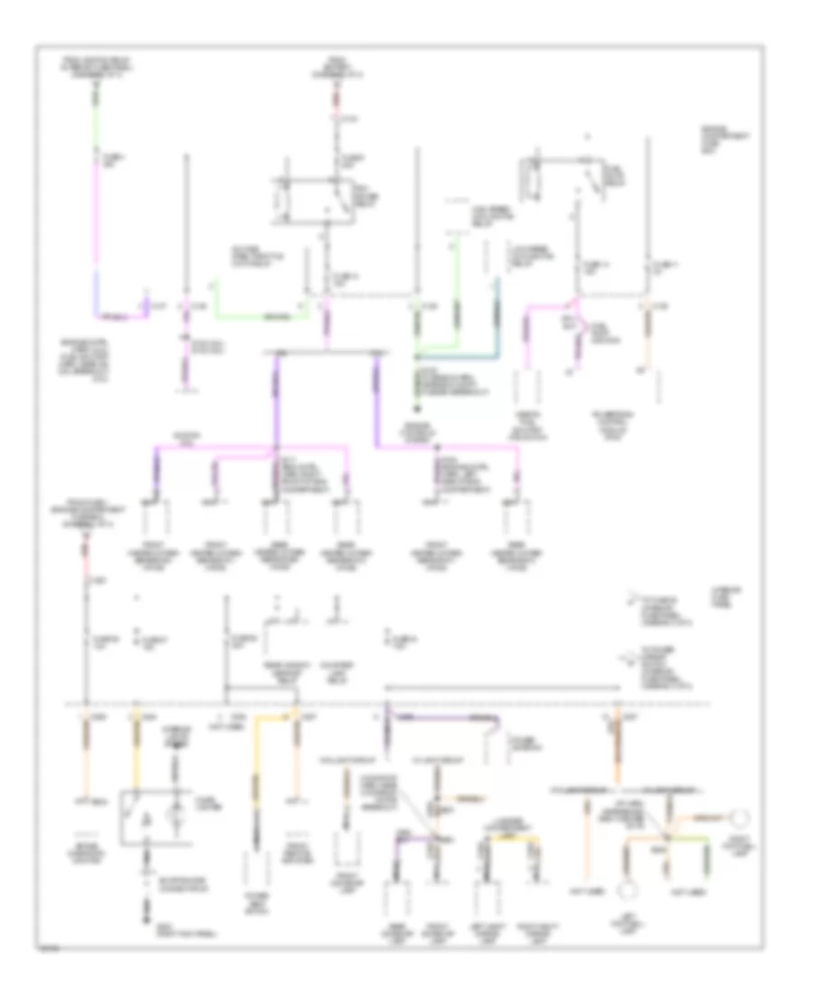
Power Distribution Wiring Diagram (1 of 3) for Mercury Mystique 1997
 https://portal-diagnostov.com/license.html
Automotive Electricians Portal FZCO
Automotive Electricians Portal FZCO
https://portal-diagnostov.com/license.html
https://portal-diagnostov.com/license.html
Automotive Electricians Portal FZCO
Automotive Electricians Portal FZCO
List of elements for Power Distribution Wiring Diagram (1 of 3) for Mercury Mystique 1997:
- (fuse box harn, above int fuse panel)
- (fuse box harn, in int fuse panel breakout) s205
- (fuse box harn, near abs control module breakout)
- (i/p harn, near inst cluster breakout) s216
- (moonroof harn, center of windshield header)
- (not used)
- 0.200
- A/t
- Abs control module
- Abs hydraulic unit
- Air temperature actuator
- Battery
- Blower motor relay
- C133
- C136
- C137
- C201
- C203
- C205
- C277
- C281
- C282
- C284
- C285
- C288
- C298
- C523
- Circuit breaker 20 10a
- Combination switch
- Combination switch (hazard switch)
- Daytime running lamps (drl) relay
- Engine compartment fuse box
- Fog lamp relay
- From ignition switch diode #2 (interior fuse panel) (diagram 3 of 3)
- Fuse 1 80a
- Fuse 10 20a
- Fuse 10 7.5a
- Fuse 12 15a
- Fuse 2 60a
- Fuse 21 40a
- Fuse 23 15a
- Fuse 3 60a
- Fuse 37 30a
- Fuse 5 15a
- Fuse 7 30a
- Gearshift lever unit
- Generator
- Heater- a/c mode switch
- High beam headlamp relay
- High speed cooling fan relay
- Horn relay
- Ignition relay
- Interior fuse panel
- Interval wiper relay
- Lo beam headlamp relay
- Low speed cooling fan relay
- M/t
- Main light switch
- Master window control switch
- Mega fuse 175a
- Moon- roof switch
- Nca
- One touch down window relay
- Park/neutral position (pnp) switch
- Red
- Resistance wire
- Right front window switch
- S173
- S175 (fuse box harn, near windshield wiper module breakout)
- S201
- S309 (door lock feed harn, near park break switch breakout)
- S503 (left front door lock jumper harn, near left front speaker breakout)
- S902
- Spare
- Speed control module
- Starter motor
- Starter relay
- To fuse 36 (interior fuse panel) (diagram 2 of 3)
- To fuse 4 (engine compartment fuse box) (diagram 2 of 3)
- To fuse 9 (engine compartment fuse box) (diagram 2 of 3)
- To ignition switch (diagram 3 of 3)
- Transmission range (tr) sensor
- W/ drl
- W/ mec iii abs
- W/o mec iii abs
- Windshield wiper motor
- Wiper/ washer switch
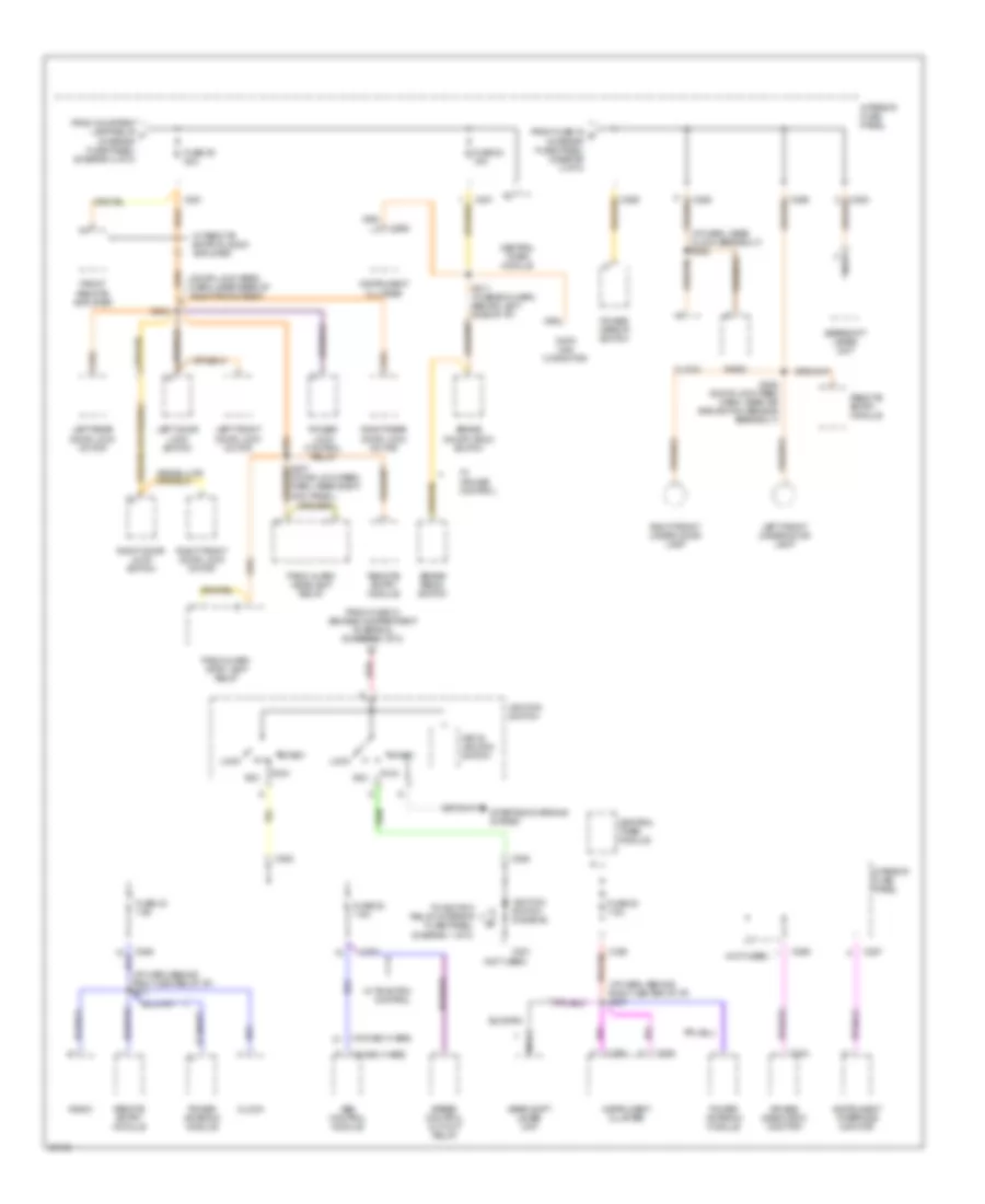
Power Distribution Wiring Diagram (2 of 3) for Mercury Mystique 1997
 https://portal-diagnostov.com/license.html
Automotive Electricians Portal FZCO
Automotive Electricians Portal FZCO
https://portal-diagnostov.com/license.html
https://portal-diagnostov.com/license.html
Automotive Electricians Portal FZCO
Automotive Electricians Portal FZCOList of elements for Power Distribution Wiring Diagram (2 of 3) for Mercury Mystique 1997:
- (engine cntrl harn) (2.0l) (fuel shutoff harn, near ign coil breakout) (2.5l)
- (fuse box harn, near eng compt fuse box breakout)
- (i/p harn, near behind right center of i/p)
- (moonfoof harn, near moonroof motor breakout)
- (not used)
- 2.0l
- 2.5l
- A/c wide open throttle (wot) relay
- Air bag diagnostic monitor
- C133
- C136
- C137
- C203
- C205
- C234
- C284
- C285
- C287
- C298
- Cigar lighter
- Courtesy lamp relay
- Engine compartment fuse box
- Engine controls system
- From battery (diagram 1 of 3)
- From fuse 1 (engine compartment fuse box) (diagram 1 of 3)
- From ignition relay (interior fuse panel) (diagram 1 of 3)
- Front dome/map lamp
- Front heated oxygen sensor #11 (ho2s)
- Front heated oxygen sensor #21 (ho2s)
- Front remote amplifier
- Fuel pump monitor
- Fuel pump relay
- Fuse 11 3a
- Fuse 13 15a
- Fuse 14 15a
- Fuse 27 15a
- Fuse 28 30a
- Fuse 34 7.5a
- Fuse 36 10a
- Fuse 4 20a
- Fuse 9 20a
- G203 (right kick panel)
- High speed cooling fan relay
- Ignition coil
- Inertia fuel shutoff (ifs) switch
- Interior fuse panel
- Interior lights system
- Left footwell lamp
- Left vanity mirror lamp
- Low speed cooling fan relay
- Luggage compartment lamp
- Nca
- Pcm power relay
- Power antenna
- Power seat switch
- Powertrain control module (pcm)
- Rear dome/map lamp
- Rear heated oxygen sensor #12 (ho2s)
- Rear heated oxygen sensor #22 (ho2s)
- Rear window defrost relay
- Red
- Right footwell lamp
- Right vanity mirror lamp
- S153 (2.0l) s132 (2.5l)
- S164 (engine cntrl harn, left side of eng compartment)
- S236
- S251
- S904
- Shorting bar connector #3
- To fuse 25 (interior fuse panel) (diagram 3 of 3)
- To power mirror switch (interior fuse panel) (diagram 3 of 3)
- W/o light group
Power Distribution Wiring Diagram (3 of 3) for Mercury Mystique 1997
 https://portal-diagnostov.com/license.html
Automotive Electricians Portal FZCO
Automotive Electricians Portal FZCO
https://portal-diagnostov.com/license.html
https://portal-diagnostov.com/license.html
Automotive Electricians Portal FZCO
Automotive Electricians Portal FZCOList of elements for Power Distribution Wiring Diagram (3 of 3) for Mercury Mystique 1997:
- (door lock feed harn, near rear of right front seat)
- (i/p harn, behind right center of i/p) s217
- (i/p harn, behind right center of i/p) s237
- (i/p harn, near clock breakout) s222
- (not used)
- (w/ mec iii abs)
- (w/o mec iii abs)
- Abs control module
- Acc
- Air bag diagnostic monitor
- Brake on/off (boo) switch
- Brake pedal switch
- C201
- C234
- C262
- C281
- C282
- C283
- C285
- C286
- C287
- C288
- C290
- Central timer module
- Clock
- Data link connctor
- From courtesy lamp relay f (interior fuse panel) (diagram 2 of 3)
- From fuse 10 (engine compartment fuse box) (diagram 1 of 3)
- From fuse 34 g (interior fuse panel) (diagram 2 of 3)
- Front remote amplifier
- Fuse 22 7.5a
- Fuse 24 15a
- Fuse 25 20a
- Fuse 30 7.5a
- Fuse 32 7.5a
- Gear shift lever unit
- Gearshift lever unit
- Ignition switch
- Ignition switch diode #2
- Instrument cluster
- Instrument interface monitor
- Interior fuse panel
- Key in ignition switch
- Left door lock switch
- Left front door lock motor
- Left front under door lamp
- Left rear door lock motor
- Lock
- Nca
- Panic alarm headlamp relay
- Panic alarm stop lamp relay
- Power antenna module
- Power lock control relay
- Power mirror switch
- Radio
- Red
- Remote entry module
- Right door lock switch
- Right front door lock motor
- Right front under door lamp
- Right rear door lock motor
- Run
- S207 (door lock feed harn, near right kick panel)
- S208 (door lock feed harn, near air bag switch sensor breakout)
- S211 (fuse box harn, behind left side of i/p)
- S304
- Speed control cut-out relay
- Start
- Starting/charging system
- To ignition relay (interior fuse panel) (diagram 1 of 3)
- W/ cruise control
- W/ remote entry & audi0 amplifier
- W/ traction control

 Čeština
 Dansk
Dansk Deutsch
 Ελληνικά
 English
 English
 Español
 Suomi
Suomi Français
 Français
 עברית
עברית Hrvatski
 Magyar
 Italiano
 日本語
日本語 Nederlands
 Polski
 Português
 Português
 Română
 Русский
 Slovenčina
 Slovenščina
 Svenska
 Türkçe
 中文 (中国)
