SUPPLEMENTAL RESTRAINTS
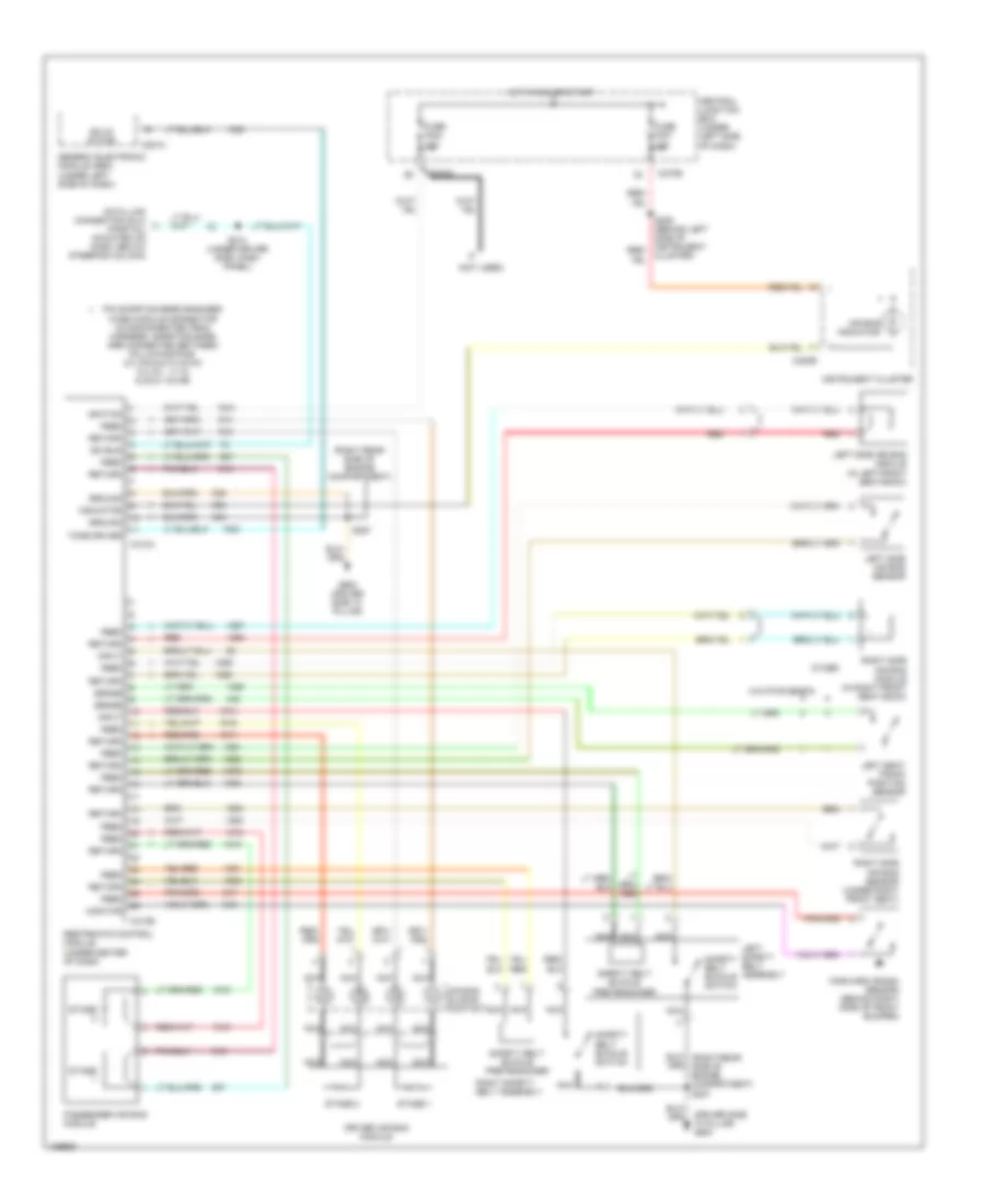
Supplemental Restraint Wiring Diagram for Ford Taurus SES 2001
 https://portal-diagnostov.com/license.html
Automotive Electricians Portal FZCO
Automotive Electricians Portal FZCO
https://portal-diagnostov.com/license.html
https://portal-diagnostov.com/license.html
Automotive Electricians Portal FZCO
Automotive Electricians Portal FZCO
List of elements for Supplemental Restraint Wiring Diagram for Ford Taurus SES 2001:
- (driver side "a' pillar) g900
- (not used)
- (right rear side of engine compartment)
- Air bag indicator
- Air bag sliding contact
- C201c
- C220b
- C270b
- C270c
- C310a
- C310b
- Central junction box (under left side of dash)
- Data link connector (dlc) (partial) (mounted on dash, below steering column)
- Driver air bag module
- Feed
- Forward crash sensor (behind right side of front bumper)
- Fuse f223 10a
- Fuse f227 10a
- G900 (driver side "a" pillar)
- Generic electronic module (gem) (under left side of dash)
- Ground
- Hot in run or start
- Ignition
- Indicator
- Input
- Instrument cluster
- Iso bus
- Left safety belt assembly
- Left seat track position sensor
- Left side air bag module (in left front seat back)
- Left side air bag sensor
- Monitor
- Nca
- Other
- Passenger air bag module
- Pin shorting bars engaged when module connector is disconnected from harness. shorting bars are connected between following pins: 2-3, 5-6 & 9-10 c310a 3-4, 6-7, 11-12 & 20-21 c310b
- Red
- Restraints control module (under center of dash)
- Return
- Right safety belt assembly
- Right side air bag module (in right front seat back)
- Right side air bag sensor (under right front seat)
- S213 (under driver side, dash panel)
- S227
- Safety belt buckle pretensioner
- Safety belt buckle switch
- Sense
- Solid state
- Stage
- Stage 1
- Stage 2
- Tone driver
- W/o pwr seats
 Čeština
 Dansk
Dansk Deutsch
 Ελληνικά
 English
 English
 Español
 Suomi
Suomi Français
 Français
 עברית
עברית Hrvatski
 Magyar
 Italiano
 日本語
日本語 Nederlands
 Polski
 Português
 Português
 Română
 Русский
 Slovenčina
 Slovenščina
 Svenska
 Türkçe
 中文 (中国)
 한국어
한국어
