WARNING SYSTEMS
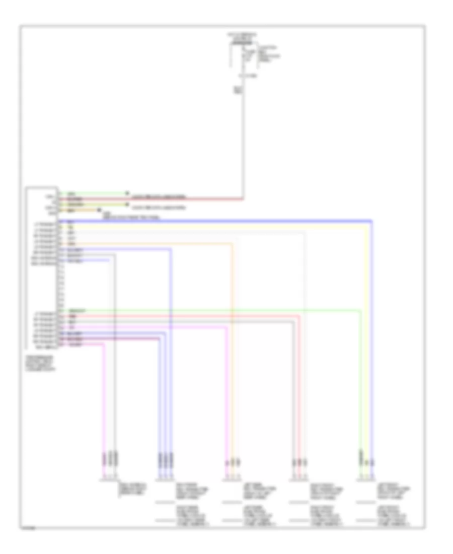
Warning Systems Wiring Diagram for MINI Cooper Paceman 2013
 https://portal-diagnostov.com/license.html
Automotive Electricians Portal FZCO
Automotive Electricians Portal FZCO
https://portal-diagnostov.com/license.html
https://portal-diagnostov.com/license.html
Automotive Electricians Portal FZCO
Automotive Electricians Portal FZCO
List of elements for Warning Systems Wiring Diagram for MINI Cooper Paceman 2013:
- Can h
- Can l
- Computer data lines system
- Fuse f19 5a
- Gnd
- Hot w/ terminal 30g relay energized
- Junction box (right kick panel)
- Left front electronic wheel module (on left front wheel assembly)
- Left front rdc transmitter (front of left front wheel)
- Left rear electronic wheel module (on left rear wheel assembly)
- Left rear rdc transmitter (front of left rear wheel)
- Lf transmit
- Lr transmit
- Rdc aerial
- Rdc antenna
- Rdc antenna (behind right rear wheel)
- Red
- Rf transmit
- Right front electronic wheel module (on right front wheel assembly)
- Right front rdc transmitter (front of right front wheel)
- Right rear electronic wheel module (on right rear wheel assembly)
- Right rear rdc transmitter (front of right rear wheel)
- Rr transmit
- Tire pressure control (rdc) (right side of luggage compt)
- X11008
- X490 (behind right rear trim panel)
 Čeština
 Dansk
Dansk Deutsch
 Ελληνικά
 English
 English
 Español
 Suomi
Suomi Français
 Français
 עברית
עברית Hrvatski
 Magyar
 Italiano
 日本語
日本語 Nederlands
 Polski
 Português
 Português
 Română
 Русский
 Slovenčina
 Slovenščina
 Svenska
 Türkçe
 中文 (中国)
 한국어
한국어
