POWER DISTRIBUTION
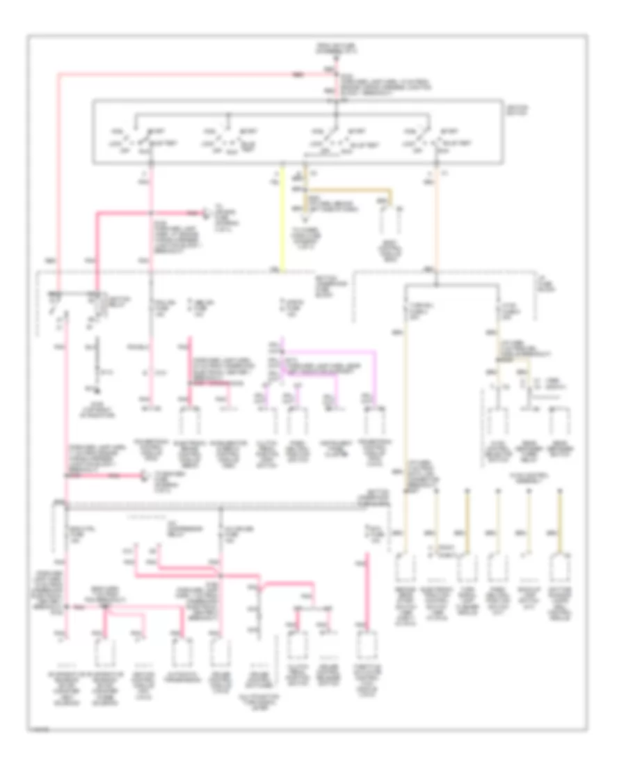
Power Distribution Wiring Diagram (1 of 4) for Pontiac Firebird 2001
 https://portal-diagnostov.com/license.html
Automotive Electricians Portal FZCO
Automotive Electricians Portal FZCO
https://portal-diagnostov.com/license.html
https://portal-diagnostov.com/license.html
Automotive Electricians Portal FZCO
Automotive Electricians Portal FZCO
List of elements for Power Distribution Wiring Diagram (1 of 4) for Pontiac Firebird 2001:
- (1999)
- (2000/2001)
- (eng harn, near powertrain control module) s106
- (forward lamp harn, 25 cm from underhood electrical center 1 breakout)
- (forward lamp harn, 4 cm from ign switch) breakout) s203
- (forward lamp harn, 8 cm from underhood electrical center 1 breakout) s168
- 30a
- A10
- Abs bat 1 fuse 40a
- Abs bat 2 fuse 50a
- Abs bat fuse 25a
- Accelerator & servo control module
- Air pump fuse 25a
- Air pump relay (vin g)
- Air solenoid relay (1999 w/vin g)
- Battery
- Blower motor relay
- Body control module (bcm)
- Bottom underhood fuse block
- Cool fan fuse 10a
- Cool fan fuse 40a
- Cooling fan 1 relay
- Cooling fan 2 relay
- Cooling fan 3 relay
- Electronic brake control module (ebcm)
- Eng ctrl fuse 50a
- Fuel pump fuse 20a
- Fuel pump relay
- Generator
- Headlamp opening door actuator control module
- Headlamp switch
- Hl door-horn fuse 50a
- Horn fuse 20a
- Horn relay
- I/p 1 fuse 40a
- I/p 2 fuse 40a
- Ign fuse 50a
- L hdlp door fuse 15a
- Nca
- Pcm bat fuse 10a
- Powertrain control module (pcm)
- R hdlp door fuse 15a
- Red
- S169 (forward lamp harn, 6 cm from underhood electrical center 1 breakout)
- S177 (forward lamp harn, 5 cm from underhood electrical center breakout)
- S179
- Secondary air injection (air) solenoid (2000/2001 vin g)
- Starter solenoid
- Tcs bat fuse 20a
- Throttle actuator control (tac) module
- To cigar accy fuse (diagram 3 of 4)
- To ignition switch pin b (diagram 2 of 4)
- To radio accy fuse (diagram 3 of 4)
- To tail lts fuse (diagram 3 of 4)
- Top underhood fuse block
- Vin g
- Vin k
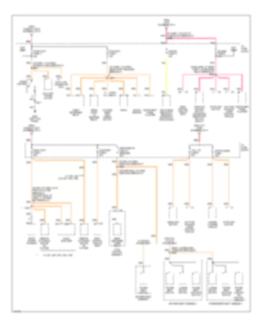
Power Distribution Wiring Diagram (2 of 4) for Pontiac Firebird 2001
 https://portal-diagnostov.com/license.html
Automotive Electricians Portal FZCO
Automotive Electricians Portal FZCO
https://portal-diagnostov.com/license.html
https://portal-diagnostov.com/license.html
Automotive Electricians Portal FZCO
Automotive Electricians Portal FZCOList of elements for Power Distribution Wiring Diagram (2 of 4) for Pontiac Firebird 2001:
- (1999) (2000-01)
- (chevy) b
- (eng harn, 7 cm from pcm breakout) s107
- (forward lamp harn, 11 cm from engine wiring harness junction block 1 breakout) s164
- (forward lamp harn, 15 cm from underhood electrical center 1 breakout) s182
- (forward lamp harn, 20 cm from underhood electrical center 1 breakout) s181
- (forward lamp harn, near left radiator support)
- (i/p harn, 2 cm from drl module breakout) s248
- (pont) a
- (vin g w/nw9)
- A/c compressor relay
- A/c cruise fuse 15a
- A/t
- Abs ign fuse 10a
- Acc
- Accelerator & servo control module (asm)
- Automatic transmission
- Back-up lamp switch (m/t)
- Body control module (bcm)
- Bottom underhood fuse block
- Bulb test
- C c
- C1 c4
- C101
- Clutch pedal position switch
- Clutch pedal positon (cpp) switch
- Cruise control module (vin g)
- Cruise control release switch
- Cruise control switches
- D10
- Daytime running lamps (drl) control module
- Electronic brake control module (ebcm)
- Electronic traction control switch (1999 w/vin g)
- Eng ctrl fuse 15a
- Etc fuse 10a
- Evaporative emission (evap) canister purge solenoid
- Evaporative emission (evap) canister vent solenoid
- From ign fuse (diagram 1 of 4)
- G109 (top right of radiator)
- Hvac control assembly
- Hvac control selector switch
- Hvac fuse 6 20a
- I/p fuse block
- Ignition control module (icm) (vin k)
- Ignition relay
- Ignition switch
- Instrument panel cluster
- Lock
- M/t
- Multifunction turn signal lever
- Nca
- Off
- Park/ neutral position switch
- Park/ neutral position switch (a/t)
- Pcm ign fuse 15a
- Pnk
- Powertrain control module (pcm)
- Powertrain control module (pcm) (vin k)
- Rear defogger switch
- Rear defogger timer/ relay
- Red
- Run
- S112
- S165 (forward lamp harn, 7 cm from underhood electrical center 2 breakout)
- S183 (forward lamp harn, 10 cm from engine wiring harness junction block 1 breakout)
- S185 (forward lamp harn, at engine wiring harness junction block 1 breakout)
- S254 (i/p harn, behind left side of dash)
- Second gear start switch (1999 chevy w/vin k)
- Start
- Strtr fuse 15a
- Throttle actuator control (tac) module (vin k)
- To air bag fuse (diagram 3 of 4)
- To eng sen fuse (diagram 4 of 4)
- To wiper/ wash fuse (diagram 4 of 4)
- Turn b/u fuse 2 20a
- Turn signal lamp flasher module
Power Distribution Wiring Diagram (3 of 4) for Pontiac Firebird 2001
 https://portal-diagnostov.com/license.html
Automotive Electricians Portal FZCO
Automotive Electricians Portal FZCO
https://portal-diagnostov.com/license.html
https://portal-diagnostov.com/license.html
Automotive Electricians Portal FZCO
Automotive Electricians Portal FZCOList of elements for Power Distribution Wiring Diagram (3 of 4) for Pontiac Firebird 2001:
- (chev)
- (dash harn, at rear compt lid release relay breakout) s206
- (i/p harn, 7 cm from rear compt release breakout)
- (ip harn, 7 cm into ip fuse block breakout) s255
- (not used)
- (pont)
- (seat jumper harn, under driver's seat) s320
- A10
- Air bag fuse 10 15a
- Audio amplifier
- Auxiliary power outlet
- Body control module (bcm)
- Cigar accy fuse 11 25a
- Cigar lighter
- Convertible: (i/p harn, near g200 breakout)
- Courtesy fuse 8 20a
- Data link connector (dlc)
- Daytime running lamps control module
- Defog/seats circuit breaker 30a
- Driver's seat assembly
- E11
- E12
- From fusible link e (diagram 1 of 4)
- From fusible link f (diagram 1 of 4)
- From i/p 2 fuse (diagram 1 of 4)
- From s185 (diagram 2 of 4)
- G200 (left kick panel)
- Gauges fuse 9 10a
- Hazard flasher module
- Headlamp switch
- Hvac control assembly
- I/p fuse block
- Inflatable restraint sensing & diagnostic module (sdm)
- Instrument panel cluster
- Lumbar adjust switch
- Nca
- Outside rear view mirror switch
- Passenger's seat assembly
- Pnk
- Pontiac, w/ dual power seat
- Power seat cushion air control module
- Power seat inflator switch
- Power seat switch
- Pwr accy fuse 7 15a
- Radio
- Radio accy fuse 4 25a
- Radio power antenna
- Rear compt lid release relay
- Rear defogger timer/ relay
- Red
- Remote playback device cd player
- S211
- S217
- S333
- Shock sensor
- Stop/hazard fuse 1 20a
- Stoplamp switch
- Tail lts fuse 5 20a
- Theft deterrent relay
- Traction control switch (or second gear start switch) (2000-01)
- W/ single power seat
- W/ uz7, u59, w53, w54, w55
- W/ w53, u62 w/o uz7, w54, w55
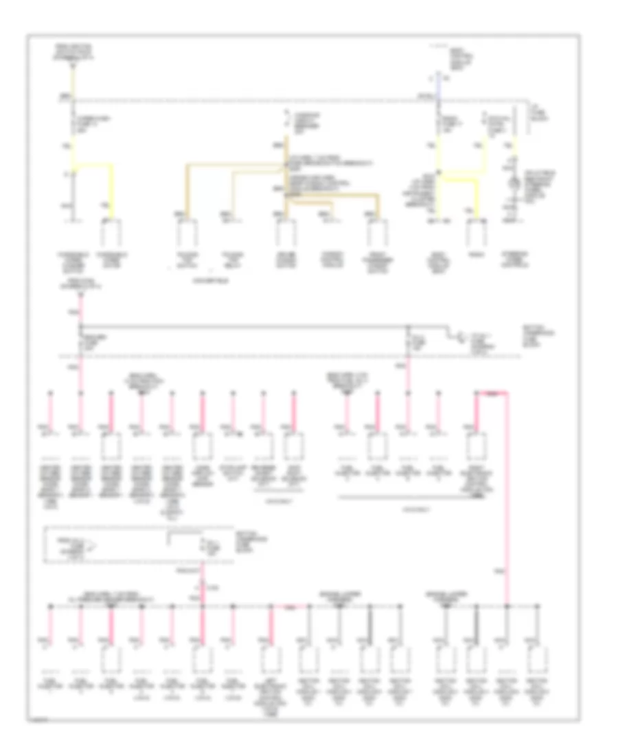
Power Distribution Wiring Diagram (4 of 4) for Pontiac Firebird 2001
 https://portal-diagnostov.com/license.html
Automotive Electricians Portal FZCO
Automotive Electricians Portal FZCO
https://portal-diagnostov.com/license.html
https://portal-diagnostov.com/license.html
Automotive Electricians Portal FZCO
Automotive Electricians Portal FZCOList of elements for Power Distribution Wiring Diagram (4 of 4) for Pontiac Firebird 2001:
- (cross car harn, near window control module breakout) s208
- (eng harn, 14 cm from pcm breakout) s104
- (eng harn, 7 cm from oil presure sender breakout) s102
- (eng harn, 8 cm from fuel inj 4 breakout) s109
- (engine jumper harness) s122
- (engine jumper harness) s124
- (i/p harn, 7 cm from park brake switch breakout) s253
- Body control module (bcm)
- Bottom underhood fuse block
- C100
- Convertible
- Driver window switch
- Eng sen fuse 20a
- Folding top relay
- Folding top switch
- From ignition switch pin e (diagram 2 of 4)
- From inj 2 fuse h (diagram 4 of 4)
- From s164 (diagram 2 of 4)
- Front passenger window switch
- Fuel injector
- Fuel injector (vin g)
- Fuel injector (vin k)
- Heated oxygen sensor (ho2s) bank 1 sensor 1
- Heated oxygen sensor (ho2s) bank 1 sensor 2 (1999 vin g & 2000-01 all)
- Heated oxygen sensor (ho2s) bank 1 sensor 3 (1999 vin k)
- Heated oxygen sensor (ho2s) bank 2 sensor 1
- Heated oxygen sensor (ho2s) bank 2 sensor 2 (vin g)
- I/p fuse block
- Ignition coil/ module 1 (2000- 01)
- Ignition coil/ module 2 (2000- 01)
- Ignition coil/ module 3 (2000- 01)
- Ignition coil/ module 4 (2000- 01)
- Ignition coil/ module 5 (2000- 01)
- Ignition coil/ module 6 (2000- 01)
- Ignition coil/ module 7 (2000- 01)
- Ignition coil/ module 8 (2000- 01)
- Inflatable restraint steering wheel module coil
- Inj 1 fuse 15a
- Inj 2 fuse 15a
- Left electronic ignition control module (icm) (vin g) (1999)
- Mass airflow (maf) sensor
- Nca
- Pnk
- Radio
- Radio fuse 17 15a
- Reverse inhibit solenoid (m/t)
- Right electronic ignition control module (icm) (1999)
- S218 (i/p harn 4 cm from instrument cluster breakout)
- Skip shift solenoid (m/t)
- Steering wheel controls
- Stg whl cntrl fuse 3 1a
- Stoplamp switch (a/t)
- To inj 1 fuse (diagram 4 of 4)
- Vin g only
- Window control module
- Windows circuit breaker 30a
- Windshield wiper motor
- Windshield wiper/ washer switch
- Wiper/wash fuse 14 25a

 Čeština
 Dansk
Dansk Deutsch
 Ελληνικά
 English
 English
 Español
 Suomi
Suomi Français
 Français
 עברית
עברית Hrvatski
 Magyar
 Italiano
 日本語
日本語 Nederlands
 Polski
 Português
 Português
 Română
 Русский
 Slovenčina
 Slovenščina
 Svenska
 Türkçe
 中文 (中国)
