RADIO
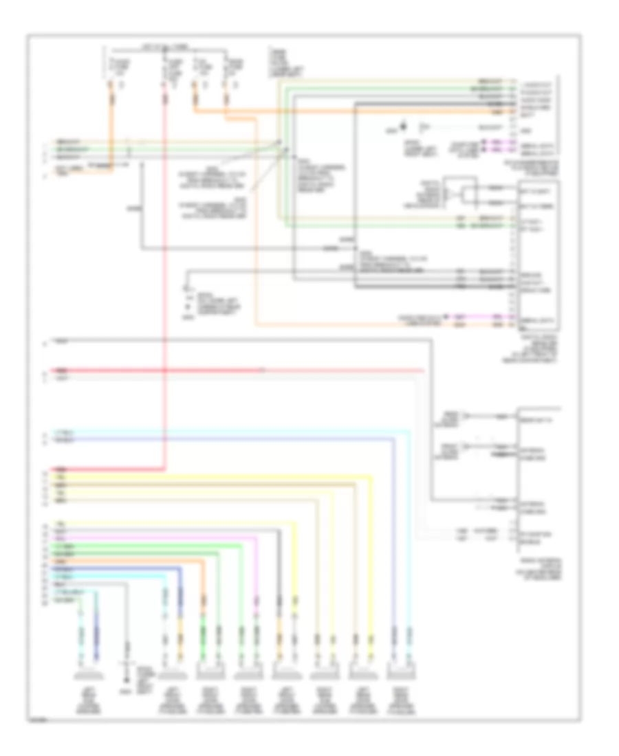
Radio Wiring Diagram, with Amplifier (1 of 2) for Pontiac Bonneville GXP 2005
 https://portal-diagnostov.com/license.html
Automotive Electricians Portal FZCO
Automotive Electricians Portal FZCO
https://portal-diagnostov.com/license.html
https://portal-diagnostov.com/license.html
Automotive Electricians Portal FZCO
Automotive Electricians Portal FZCO
List of elements for Radio Wiring Diagram, with Amplifier (1 of 2) for Pontiac Bonneville GXP 2005:
- 14 v ref
- A10
- A11
- A12
- A13
- A14
- A15
- A16
- Am/ fm
- Amp pres sig
- Amp sns
- Antenna
- Audio amplifier (under right side of rear package shelf)
- B10
- B11
- B12
- B13
- B14
- B15
- B16
- Bare
- Batt
- Com audio in
- Computer data lines system
- Dash integration module (dim) (behind right side of dash, under sound insulator)
- Data
- Enable
- Fm comp sig
- G201
- G300
- Gnd
- Ground
- Ill
- Inflatable restraint steering wheel module coil (left kick panel)
- Interior lights system
- L audio in
- Left steering wheel controls
- Left sub +
- Left sub -
- Lf aud sig +
- Lf aud sig -
- Lf mid out +
- Lf mid out -
- Lf spkr
- Lf tweeter +
- Lf tweeter -
- Low ref
- Lr aud sig +
- Lr aud sig -
- Lr spkr
- Lr spkr +
- Lr spkr -
- Mute
- Nca
- Play
- Pnk
- R audio in
- R sub out +
- R sub out -
- Radio
- Radio on sig
- Red
- Rf aud sig +
- Rf aud sig -
- Rf mid out +
- Rf mid out -
- Rf spkr
- Rf tweeter +
- Rf tweeter -
- Right steering wheel controls
- Rr aud sig +
- Rr aud sig -
- Rr spkr
- Rr spkr +
- Rr spkr -
- S203
- Seek dn
- Seek up
- Set
- Shield gnd
- Sp201 (on right front door pillar)
- Sp300 (under left front seat)
- Steering column fuse holder (near base of steering column)
- Switch fuse 2a
- Tan
- Vehicle communication interface module (vcim) (behind right rear seat back)
- Voice sig
- Vol dn
- Vol up
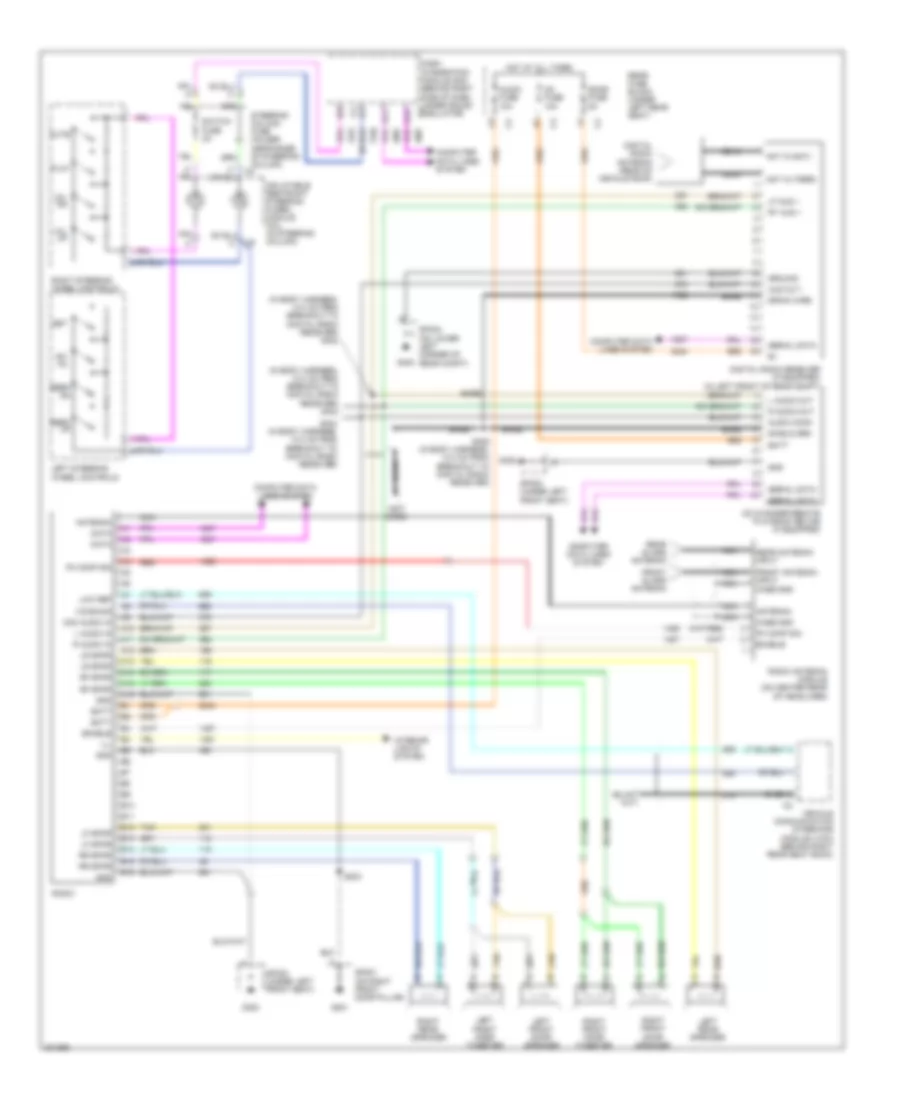
Radio Wiring Diagram, with Amplifier (2 of 2) for Pontiac Bonneville GXP 2005
 https://portal-diagnostov.com/license.html
Automotive Electricians Portal FZCO
Automotive Electricians Portal FZCO
https://portal-diagnostov.com/license.html
https://portal-diagnostov.com/license.html
Automotive Electricians Portal FZCO
Automotive Electricians Portal FZCOList of elements for Radio Wiring Diagram, with Amplifier (2 of 2) for Pontiac Bonneville GXP 2005:
- (not used)
- A bare
- Ant in (sat)
- Ant in (terr)
- Antenna
- Aud out -
- Audio amp fuse 20a
- Audio comm
- Audio fuse 10a
- Bare
- Batt
- Case gnd
- Cd changer-remote playback device (if equipped)
- Cd fuse 10a
- Coax
- Computer data lines system
- Digital radio antenna (rear of vehicle roof)
- Digital radio receiver (if equipped) (in left front of rear compartment)
- Drain wire
- Enable
- Fm comp sig
- Front glass antenna
- G300
- G402
- Gnd
- Ground
- Hot at all times
- L audio out
- Left front door speaker (tweeter)
- Left front door speaker (twiddler)
- Left rear door speaker (twiddler)
- Left rear sub woofer speaker
- Lf aud +
- Nca
- R audio out
- Radio antenna module (on center rear of headliner)
- Rear ant in
- Rear fuse block (under left rear seat)
- Rear glass antenna
- Red
- Right front door speaker (tweeter)
- Right front door speaker (twiddler)
- Right rear door speaker (twiddler)
- Right rear sub woofer speaker
- Rt aud +
- S402 (in body harness, 10.0 cm from breakout to digital radio receiver)
- S403 (in body harness, 10.0 cm from breakout to digital radio receiver)
- S404 (in body harness, 10.0 cm from breakout to digital radio receiver)
- S405 (in body harness, 10.0 cm from breakout to digital radio receiver)
- Sdar fuse 5a
- Serial data
- Shield grd
- Sp300 (under left front seat)
- Sp402 (on lower left corner of rear compartment)
- Tan
Radio Wiring Diagram, without Amplifier for Pontiac Bonneville GXP 2005
 https://portal-diagnostov.com/license.html
Automotive Electricians Portal FZCO
Automotive Electricians Portal FZCO
https://portal-diagnostov.com/license.html
https://portal-diagnostov.com/license.html
Automotive Electricians Portal FZCO
Automotive Electricians Portal FZCOList of elements for Radio Wiring Diagram, without Amplifier for Pontiac Bonneville GXP 2005:
- (in body harness, 10.0 cm from breakout to digital radio receiver) s402
- (in body harness, 10.0 cm from breakout to digital radio receiver) s403
- (not used)
- A10
- A11
- A12
- A13
- A14
- A15
- A16
- Am/ fm
- Ant in (sat)
- Ant in (terr)
- Antenna
- Aud out -
- Audio comm
- Audio fuse 10a
- B10
- B11
- B12
- B13
- B14
- B15
- B16
- Bare
- Batt
- Case gnd
- Cd changer-remote playback device (if equipped)
- Cd fuse 10a
- Coax
- Com audio in
- Computer data lines system
- Dash integration module (dim) (behind right side of dash, under sound insulator) c2
- Data
- Digital radio antenna (rear of vehicle roof)
- Digital radio receiver (if equipped) (in left front of rear compt)
- Drain wire
- Enable
- Fm comp sig
- Front antenna input case gnd
- Front glass antenna
- G201
- G300
- G402
- Gnd
- Ground
- Hot at all times
- Ill
- Inflatable restraint steering wheel module coil (in steering column)
- Interior lights system
- L audio in
- L audio out
- Left front door speaker
- Left front door tweeter
- Left rear speaker
- Left steering wheel controls
- Lf aud +
- Lf spkr
- Low ref
- Lr spkr
- Mute
- Nca
- Play
- R audio in
- R audio out
- Radio
- Radio antenna module (on center rear of headliner)
- Rear antenna input
- Rear fuse block (under left rear seat)
- Rear glass antenna
- Red
- Rf spkr
- Right front door speaker
- Right front door tweeter
- Right rear speaker
- Right steering wheel controls
- Rr spkr
- Rt aud +
- S203
- S404 (in body harness, 10.0 cm from breakout to digital radio receiver)
- S405 (in body harness, 10.0 cm from breakout to digital radio receiver)
- Sdar fuse 5a
- Seek dn
- Seek up
- Serial data
- Set
- Shield grd
- Sp201 (on right front door pillar)
- Sp300 (under left front seat)
- Sp402 (on lower left corner of rear compt)
- Steering column fuse holder (near base of steering column) c4
- Switch fuse 2a
- Tan
- Vehicle communication interface module (vcim) (behind right rear seat back)
- Voice sig
- Vol dn
- Vol up

 Čeština
 Dansk
Dansk Deutsch
 Ελληνικά
 English
 English
 Español
 Suomi
Suomi Français
 Français
 עברית
עברית Hrvatski
 Magyar
 Italiano
 日本語
日本語 Nederlands
 Polski
 Português
 Português
 Română
 Русский
 Slovenčina
 Slovenščina
 Svenska
 Türkçe
 中文 (中国)
