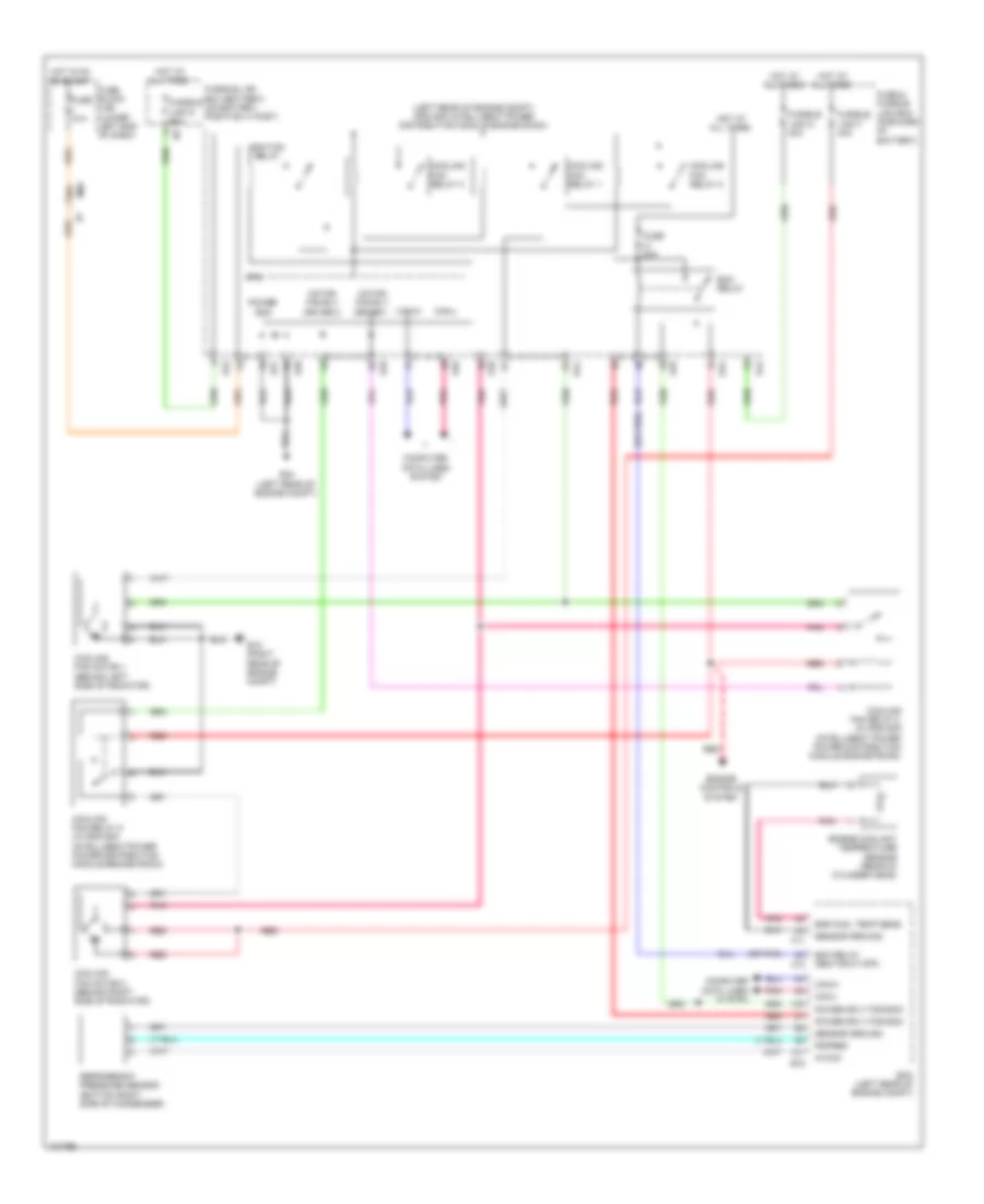
COOLING FAN
Cooling Fan Wiring Diagram for Nissan NV200 Taxi 2014
 https://portal-diagnostov.com/license.html
Automotive Electricians Portal FZCO
Automotive Electricians Portal FZCO
https://portal-diagnostov.com/license.html
https://portal-diagnostov.com/license.html
Automotive Electricians Portal FZCO
Automotive Electricians Portal FZCO
List of elements for Cooling Fan Wiring Diagram for Nissan NV200 Taxi 2014:
- (left rear of engine compt) ipdm e/r (intelligent power distribution module engine room)
- (or pnk)
- 26a
- Avcc2
- Can-h
- Can-l
- Computer data lines system
- Cooling fan motor 1 (behind left side of radiator)
- Cooling fan motor 2 (behind right side of radiator)
- Cooling fan relay 1
- Cooling fan relay 2
- Cooling fan relay 3
- Cooling fan relay 4 (in ipdm e/r (intelligent power power distribution module engine room))
- Cooling fan relay 5 (in ipdm e/r (intelligent power power distribution module engine room))
- Cpu
- E15 (right rear of engine compt)
- E16
- E24 (left rear of engine compt)
- E42
- E43
- E44
- E45
- E46
- E47
- E48
- E49
- Ecm (left rear of engine compt)
- Ecm relay
- Ecm relay (self shut-off)
- Eng cool temp sens
- Engine controls system
- Engine coolant temperature sensor (rear of cylinder head)
- F10
- F11
- Fuse & fusible link box (forward of battery)
- Fuse 10a
- Fuse 20a
- Fuse block (j/b) (lower left end of dash)
- Fusible link box (battery) (on battery positive (+) post)
- Fusible link d 60a
- Fusible link f 40a
- Fusible link g 40a
- Hot at all times
- Hot in on or start
- Ignition relay
- M69
- Motor fan-rly driver 1
- Motor fan-rly driver 2
- Pdpres
- Pnk
- Power gnd
- Power sply for ecm
- Red
- Refrigerant pressure sensor (bottom right side of condenser)
- Sensor ground
 Čeština
 Dansk
Dansk Deutsch
 Ελληνικά
 English
 English
 Español
 Suomi
Suomi Français
 Français
 עברית
עברית Hrvatski
 Magyar
 Italiano
 日本語
日本語 Nederlands
 Polski
 Português
 Português
 Română
 Русский
 Slovenčina
 Slovenščina
 Svenska
 Türkçe
 中文 (中国)
 한국어
한국어
