ELECTRONIC SUSPENSION
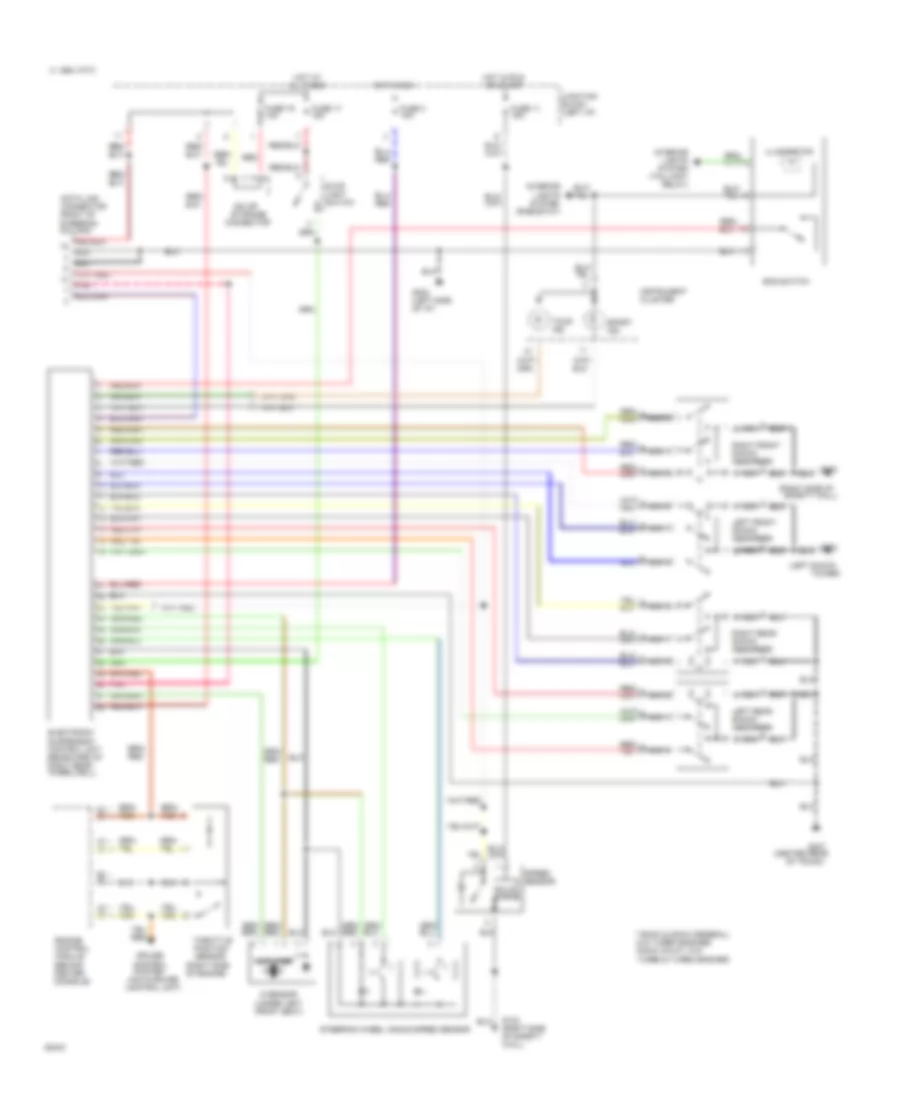
Electronic Suspension Wiring Diagram for Mitsubishi 3000GT VR-4 1994
 https://portal-diagnostov.com/license.html
Automotive Electricians Portal FZCO
Automotive Electricians Portal FZCO
https://portal-diagnostov.com/license.html
https://portal-diagnostov.com/license.html
Automotive Electricians Portal FZCO
Automotive Electricians Portal FZCO
List of elements for Electronic Suspension Wiring Diagram for Mitsubishi 3000GT VR-4 1994:
- (auto-cruise control unit)
- (center rear
- (left shock
- (right side of
- (right side of engine)
- (under left front seat)
- * **
- **sohc & dohc (federal) w/o turbo engines *dohc (calif.) w/o turbo & turbo engines
- 1994 vftc c
- All times
- Amplifier
- Connector
- Control system
- Cruise
- Data link connector (right of steering column)
- Ecs switch
- Electronic suspension control unit (rearward of right rear wheelwell)
- Engine control module (behind center console)
- Fuse 11 15a
- Fuse 17 15a
- Fuse 19 10a
- Fuse 3 10a
- G sensor
- G102
- G123
- G123 (right side of safety wall)
- G202 (left side of i/p)
- G407
- Hot at
- Hot in run
- Hot in run or start
- Illumination
- Instrument cluster
- Interior lights system (rheostat)
- Interior lights system (taillight relay)
- Iod or storage
- Junction block (left i/p)
- Left front shock absorber
- Left rear shock absorber
- Nca
- Of trunk)
- Pnk
- Red
- Right front shock absorber
- Right rear shock absorber
- Safety wall)
- Solid state
- Speed sensor
- Sport ind.
- Steering wheel angle speed sensor
- Stop light switch
- Throttle position sensor
- Tour ind.
- Tower)
 Čeština
 Dansk
Dansk Deutsch
 Ελληνικά
 English
 English
 Español
 Suomi
Suomi Français
 Français
 עברית
עברית Hrvatski
 Magyar
 Italiano
 日本語
日本語 Nederlands
 Polski
 Português
 Português
 Română
 Русский
 Slovenčina
 Slovenščina
 Svenska
 Türkçe
 中文 (中国)
 한국어
한국어
