ENGINE PERFORMANCE
4.0L
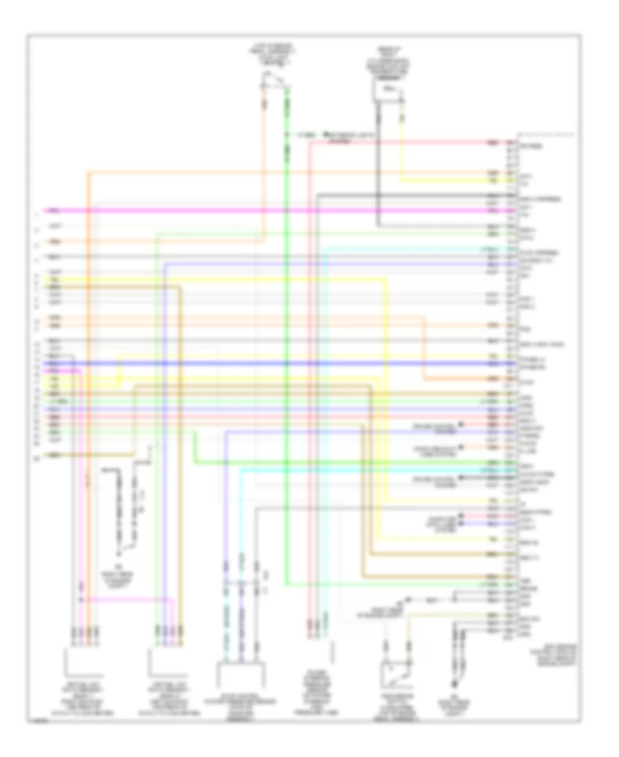
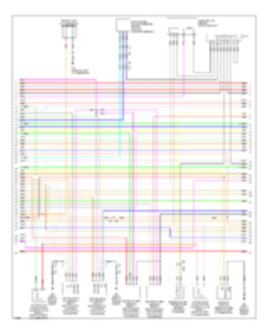
4.0L, Engine Performance Wiring Diagram (1 of 6) for Nissan NV2500 HD S 2014
 https://portal-diagnostov.com/license.html
Automotive Electricians Portal FZCO
Automotive Electricians Portal FZCO
https://portal-diagnostov.com/license.html
https://portal-diagnostov.com/license.html
Automotive Electricians Portal FZCO
Automotive Electricians Portal FZCO
List of elements for 4.0L, Engine Performance Wiring Diagram (1 of 6) for Nissan NV2500 HD S 2014:
- Af-h1
- Af-h2
- Avcc1 tps
- Batt
- C-vtc l
- C-vtc r
- Close
- E9 (right rear of engine compt)
- Ecm (engine control module) (right rear of engine compt)
- Electric throttle control actuator (on throttle body assembly)
- Evap
- F14
- F32
- F54
- F77
- Fpr
- Gnd
- Gnd a
- Gnd a pdpres
- Gnd a tps
- Heated oxygen sensor 2 (bank 1) (right exhaust, downstream of catalytic converter)
- Heated oxygen sensor 2 (bank 2) (left exhaust, downstream of catalytic converter)
- Ign 1
- Ign 2
- Ign 3
- Ign 4
- Ign 5
- Ign 6
- Inj 1
- Inj 2
- Inj 3
- Inj 4
- Inj 5
- Inj 6
- Mot rly
- Mtr 1
- Mtr 2
- Nca
- O2 hrl
- O2 hrr
- O2 srl
- O2 srr
- Open
- Pdpress
- Pnk
- Red
- Sensor 1
- Sensor 2
- Ssoff
- Throttle control motor
- Throttle position sensor
- Tps 1
- Tps 2
- V mot
- Vias
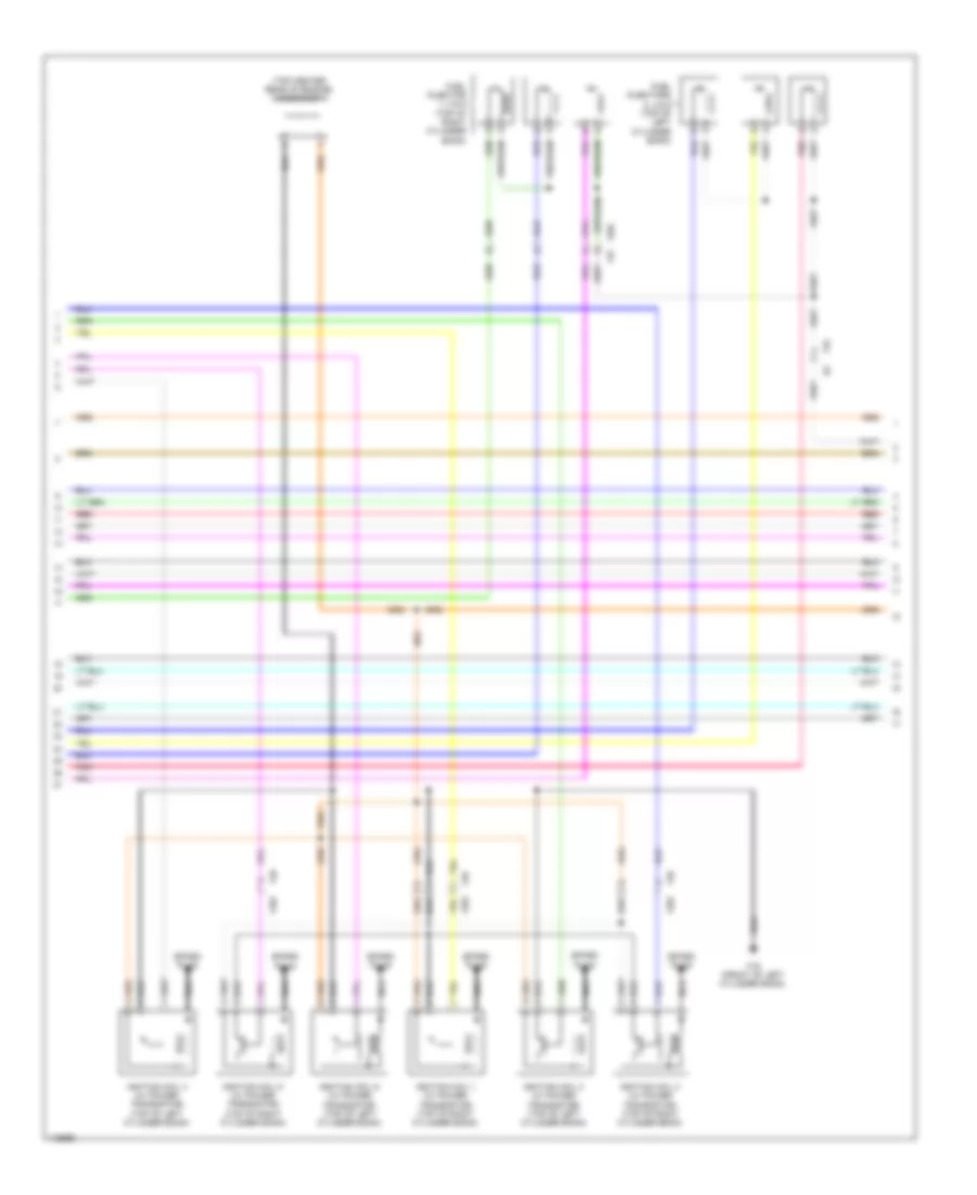
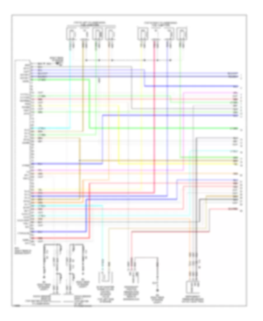
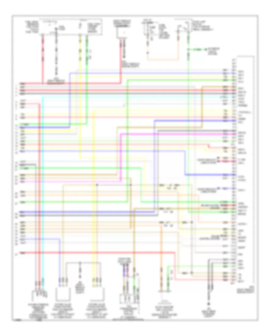
4.0L, Engine Performance Wiring Diagram (2 of 6) for Nissan NV2500 HD S 2014
 https://portal-diagnostov.com/license.html
Automotive Electricians Portal FZCO
Automotive Electricians Portal FZCO
https://portal-diagnostov.com/license.html
https://portal-diagnostov.com/license.html
Automotive Electricians Portal FZCO
Automotive Electricians Portal FZCOList of elements for 4.0L, Engine Performance Wiring Diagram (2 of 6) for Nissan NV2500 HD S 2014:
- (top center rear of engine) condenser 1
- F16 (front of left cylinder bank)
- F201
- F204 f37
- F26
- F32
- Fuel injector 1, 3 & 5 (top of right cylinder bank)
- Fuel injectors 2, 4 & 6 (top of left cylinder bank)
- Ignition coil 1 (w/ power transistor) (top of right cylinder bank)
- Ignition coil 2 (w/ power transistor) (top of left cylinder bank)
- Ignition coil 3 (w/ power transistor) (top of right cylinder bank)
- Ignition coil 4 (w/ power transistor) (top of left cylinder bank)
- Ignition coil 5 (w/ power transistor) (top of right cylinder bank)
- Ignition coil 6 (w/ power transistor) (top of left cylinder bank)
- Nca
- Pnk
- Red
- Spark plug
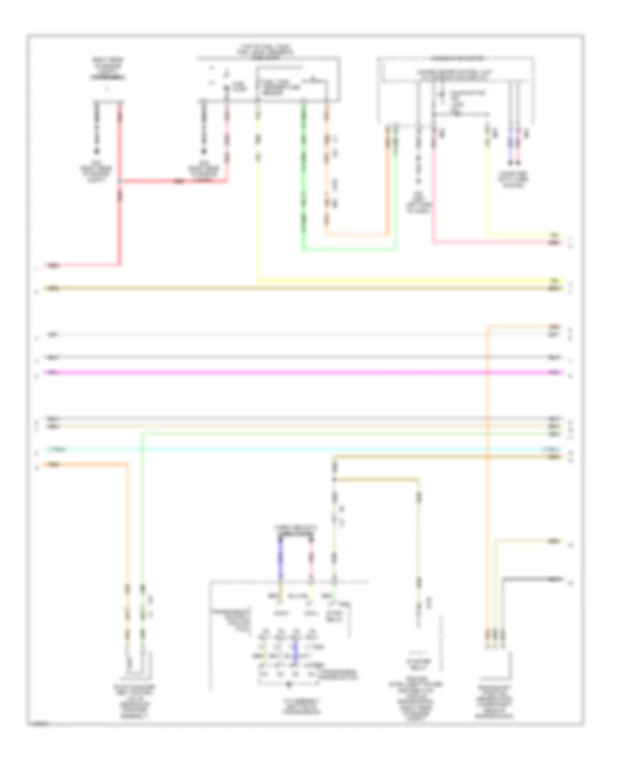
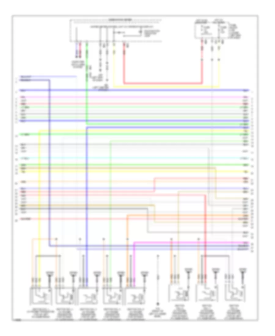
4.0L, Engine Performance Wiring Diagram (3 of 6) for Nissan NV2500 HD S 2014
 https://portal-diagnostov.com/license.html
Automotive Electricians Portal FZCO
Automotive Electricians Portal FZCO
https://portal-diagnostov.com/license.html
https://portal-diagnostov.com/license.html
Automotive Electricians Portal FZCO
Automotive Electricians Portal FZCOList of elements for 4.0L, Engine Performance Wiring Diagram (3 of 6) for Nissan NV2500 HD S 2014:
- Cpu
- E119
- E121
- E122
- Ecm relay
- F201
- F26
- F32
- Fuel pump relay
- Fuse 15a
- Fuse 20a
- Hot at all times
- Hot w/ ignition relay energized
- Intake valve timing control solenoid valve (bank 1) (front of right cylinder bank)
- Intake valve timing control solenoid valve (bank 2) (front of left cylinder bank)
- Ipdm e/r (intelligent power distribution module engine room) (right rear of engine compt)
- Red
- Throttle control motor relay
- Vias control solenoid valve (top center of engine)
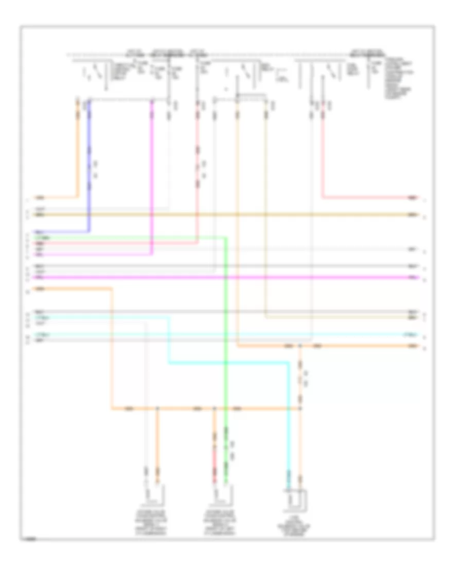
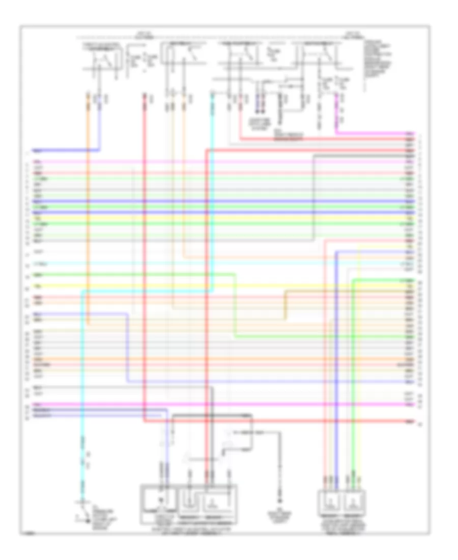
4.0L, Engine Performance Wiring Diagram (4 of 6) for Nissan NV2500 HD S 2014
 https://portal-diagnostov.com/license.html
Automotive Electricians Portal FZCO
Automotive Electricians Portal FZCO
https://portal-diagnostov.com/license.html
https://portal-diagnostov.com/license.html
Automotive Electricians Portal FZCO
Automotive Electricians Portal FZCOList of elements for 4.0L, Engine Performance Wiring Diagram (4 of 6) for Nissan NV2500 HD S 2014:
- (right rear of engine compt) condenser 2
- (top of fuel tank) fuel level sensor & fuel pump
- 17g
- 18g
- 20c
- 30c
- 31c
- 42c
- 44c
- 52c
- A/t assembly (bottom of transmission)
- Can-h
- Can-l
- Combination meter
- Computer data lines system
- Crankshaft position sensor (pos) (lower right rear of engine block)
- E122
- E15 (right rear of engine compt)
- E152
- E41
- Evap canister vent control valve (near evap canister assembly)
- F14
- F502
- F503
- F505
- Fuel pump
- Fuel tank temperature sensor
- Ipdm e/r (intelligent power distribution module engine room) (right rear of engine compt)
- M23
- M24
- M31
- M57 (left left side of dash)
- Malfunction ind lamp (mil)
- Pnk
- Red
- Start relay
- Starter relay
- Tr sw 1
- Tr sw 2
- Tr sw 3
- Tr sw 4
- Transmission control module (tcm)
- Transmission range switch
- Unified meter control unit (w/ information display)
4.0L, Engine Performance Wiring Diagram (5 of 6) for Nissan NV2500 HD S 2014
 https://portal-diagnostov.com/license.html
Automotive Electricians Portal FZCO
Automotive Electricians Portal FZCO
https://portal-diagnostov.com/license.html
https://portal-diagnostov.com/license.html
Automotive Electricians Portal FZCO
Automotive Electricians Portal FZCOList of elements for 4.0L, Engine Performance Wiring Diagram (5 of 6) for Nissan NV2500 HD S 2014:
- (air intake duct) mass air flow (maf) sensor
- (on a/c liquid tank) refrigerant pressure sensor
- Accelerator pedal position sensor (top of accelerator pedal assembly)
- Camshaft position sensor (phase) (bank 1) (rear of right cylinder bank)
- Camshaft position sensor (phase) (bank 2) (rear of left cylinder bank)
- E51
- E9 (right rear of engine compt)
- Evap canister purge volume control solenoid valve (top left front of engine)
- F14
- F202
- F32
- F35
- Fuse 10a
- Fuse block (j/b) (lower left end of dash)
- Hot at all times
- Hot in on or start
- Iat sensor
- Joint connector m04 (right end of dash)
- Knock sensor (bank 1) (inner front side of right cylinder bank)
- Knock sensor (bank 2) (inner rear side of left cylinder bank)
- M39
- Red
- Sensor 1
- Sensor 2
- W/ ascd
- W/o ascd
4.0L, Engine Performance Wiring Diagram (6 of 6) for Nissan NV2500 HD S 2014
 https://portal-diagnostov.com/license.html
Automotive Electricians Portal FZCO
Automotive Electricians Portal FZCO
https://portal-diagnostov.com/license.html
https://portal-diagnostov.com/license.html
Automotive Electricians Portal FZCO
Automotive Electricians Portal FZCOList of elements for 4.0L, Engine Performance Wiring Diagram (6 of 6) for Nissan NV2500 HD S 2014:
- (rear of right cylinder bank) engine coolant temperature sensor
- (right rear of engine compt)
- (top of brake pedal assembly) stop lamp switch
- 45c
- 46c
- 47c
- A/f+1
- A/f+2
- A/f-1
- A/f-2
- Air fuel (a/f) ratio sensor 1 (bank 1) (right exhaust, upstream of catalytic converter)
- Air fuel (a/f) ratio sensor 1 (bank 2) (left exhaust, upstream of catalytic converter)
- Aps1
- Aps2
- Ascd brake switch (if equipped) (top of brake pedal assembly)
- Ascd sw
- Avcc
- Avcc (pspres)
- Avcc2
- Avcc2 ftprs
- Bnc sw
- Brake
- Can h
- Can l
- Cdcv
- Computer data lines system
- Cruise control system
- E16
- E41
- E9 (right rear of engine compt)
- Ecm (engine control module) (right rear of engine compt)
- Evap control system pressure sensor (on evap canister assembly)
- Exterior lights system
- F14
- F77
- Ft6prs
- Gnd
- Gnd a
- Gnd a knk1 knk2
- Gnd a pspress
- Gnd a2
- Gnda ascd
- Gnda ftprs
- Ign sw
- K line
- Knk 1
- Knk 2
- Neut h
- Phase lh
- Phase rh
- Pnk
- Pos
- Power steering pressure sensor (on power steering high- pressure tube)
- Ps pres
- Qa gnda ta1
- Qa+
- Red
- Ta1
- Vbr
5.6L
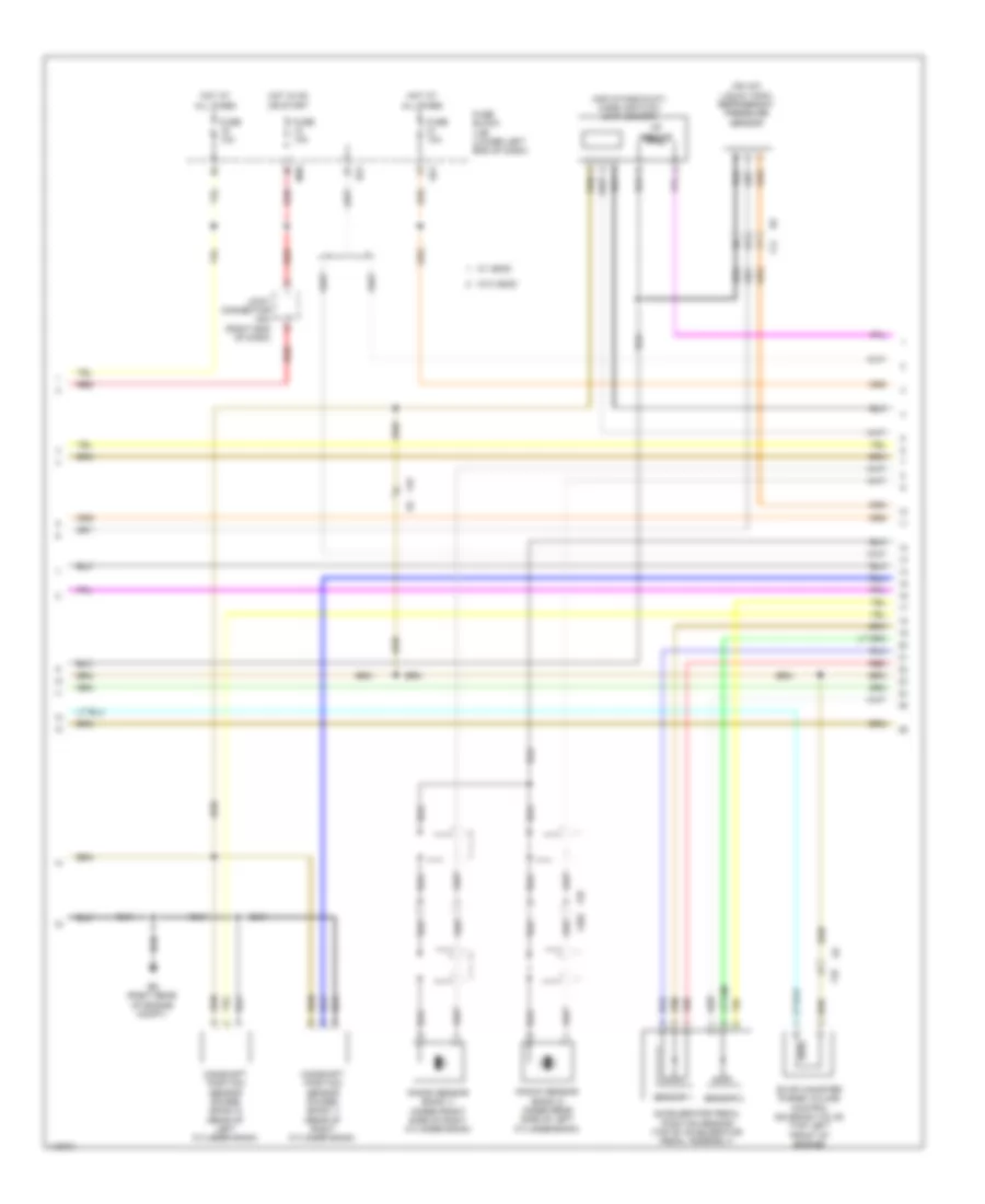
5.6L, Engine Performance Wiring Diagram (1 of 5) for Nissan NV2500 HD S 2014
 https://portal-diagnostov.com/license.html
Automotive Electricians Portal FZCO
Automotive Electricians Portal FZCO
https://portal-diagnostov.com/license.html
https://portal-diagnostov.com/license.html
Automotive Electricians Portal FZCO
Automotive Electricians Portal FZCOList of elements for 5.6L, Engine Performance Wiring Diagram (1 of 5) for Nissan NV2500 HD S 2014:
- (right rear of engine compt)
- (top of left cylinder bank) fuel injectors
- (top of right cylinder bank) fuel injectors
- A/f+2
- A/f1
- Af+1
- Af-h1
- Af-h2
- Avcc
- Avcc (pdp)
- Avcc 2
- C-vtc(l)
- C-vtc(r)
- Crankshaft position sensor (pos) (lower right rear of engine block)
- E9 (right rear of engine compt)
- Ecm (right rear of engine compt)
- Evap
- Evap canister purge volume control solenoid valve (top left side of engine)
- F14
- F72
- Ftprs
- Gnd
- Ign 7
- Inj 1
- Inj 2
- Inj 3
- Inj 4
- Inj 5
- Inj 6
- Inj 7
- Knk 2
- Knk1
- Knock sensor (bank 1) (top center of left cylinder bank)
- Knock sensor (bank 2) (top center of right cylinder bank)
- Motor 1
- Motor 2
- Nca
- O2hrl
- O2hrr
- O2srl
- Phase
- Pnk
- Pos
- Ps-pres
- Pwr sply
- Pwr sup
- Qa+
- Red
- Refrigerant pressure sensor (on a/c liquid tank)
- Sig
- Tps 1
- Vmot
- Vtcpus (r)
5.6L, Engine Performance Wiring Diagram (2 of 5) for Nissan NV2500 HD S 2014
 https://portal-diagnostov.com/license.html
Automotive Electricians Portal FZCO
Automotive Electricians Portal FZCO
https://portal-diagnostov.com/license.html
https://portal-diagnostov.com/license.html
Automotive Electricians Portal FZCO
Automotive Electricians Portal FZCOList of elements for 5.6L, Engine Performance Wiring Diagram (2 of 5) for Nissan NV2500 HD S 2014:
- 17g
- Combination meter
- Computer data lines system
- E152
- E51
- F16 (front of left cylinder bank)
- Fuse 10a
- Fuse block (j/b) (lower left end of dash)
- Hot at all times
- Hot in on or start
- Ignition coil 1 (w/ power transistor) (top of left cylinder bank)
- Ignition coil 2 (w/ power transistor) (top of right cylinder bank)
- Ignition coil 3 (w/ power transistor) (top of left cylinder bank)
- Ignition coil 4 (w/ power transistor) (top of right cylinder bank)
- Ignition coil 5 (w/ power transistor) (top of left cylinder bank)
- Ignition coil 6 (w/ power transistor) (top of right cylinder bank)
- Ignition coil 7 (w/ power transistor) (top of left cylinder bank)
- Ignition coil 8 (w/ power transistor) (top of right cylinder bank)
- M23
- M24
- M31
- M39
- M57 (left end of dash)
- M61 (left center of dash)
- Malfunction indicator lamp
- Nca
- Pnk
- Red
- Spark plug
- Unified meter control unit (w/ information display)
5.6L, Engine Performance Wiring Diagram (3 of 5) for Nissan NV2500 HD S 2014
 https://portal-diagnostov.com/license.html
Automotive Electricians Portal FZCO
Automotive Electricians Portal FZCO
https://portal-diagnostov.com/license.html
https://portal-diagnostov.com/license.html
Automotive Electricians Portal FZCO
Automotive Electricians Portal FZCOList of elements for 5.6L, Engine Performance Wiring Diagram (3 of 5) for Nissan NV2500 HD S 2014:
- Accelerator pedal position (app) sensor (top of accelerator pedal assembly)
- Close
- Computer data lines system
- Cpu
- E119
- E121
- E122
- E124
- E15 (right rear of engine compt)
- E9 (right rear of engine compt)
- Ecm relay
- Electric throttle control actuator (on throttle body assembly)
- F14
- F32
- Fuel pump relay
- Fuse 15a
- Fuse 20a
- Hot at all times
- Ignition relay
- Ipdm e/r (intelligent power distribution module engine room) (right rear of engine compt)
- Nca
- Oil pressure switch (lower left front of engine)
- Open
- Pnk
- Red
- Sensor 1
- Sensor 2
- Throttle control motor
- Throttle control motor relay
- Throttle position sensor
5.6L, Engine Performance Wiring Diagram (4 of 5) for Nissan NV2500 HD S 2014
 https://portal-diagnostov.com/license.html
Automotive Electricians Portal FZCO
Automotive Electricians Portal FZCO
https://portal-diagnostov.com/license.html
https://portal-diagnostov.com/license.html
Automotive Electricians Portal FZCO
Automotive Electricians Portal FZCOList of elements for 5.6L, Engine Performance Wiring Diagram (4 of 5) for Nissan NV2500 HD S 2014:
- (rear of left cylinder bank) condenser 1
- 45c
- 46c
- 47c
- Af+
- Af-
- Air fuel ratio (a/f) sensor 1 (bank 1) (left exhaust, upstream of catalytic converter)
- Air fuel ratio (a/f) sensor 1 (bank 2) (right exhaust, upstream of catalytic converter)
- Camshaft position sensor (phase) (front of left cylinder bank)
- E41
- E9 (right rear of engine compt)
- Engine coolant temperature sensor (top front of engine)
- Evap control system pressure sensor (on evap canister assembly)
- F14
- F16 (front of left cylinder bank)
- F203
- F32
- F36
- Gnd
- Heated oxygen sensor 2 (bank 1) (left exhaust, downstream of catalytic converter)
- Heated oxygen sensor 2 (bank 2) (right exhaust, downstream of catalytic converter)
- Htr gnd
- Htr pwr
- Intake valve timing control solenoid valve (bank 1) (front of left cylinder bank)
- Intake valve timing control solenoid valve (bank 2) (front of right cylinder bank)
- J/c f1
- Mass air flow sensor (air intake duct)
- Pwr sply
- Red
- Sig
5.6L, Engine Performance Wiring Diagram (5 of 5) for Nissan NV2500 HD S 2014
 https://portal-diagnostov.com/license.html
Automotive Electricians Portal FZCO
Automotive Electricians Portal FZCO
https://portal-diagnostov.com/license.html
https://portal-diagnostov.com/license.html
Automotive Electricians Portal FZCO
Automotive Electricians Portal FZCOList of elements for 5.6L, Engine Performance Wiring Diagram (5 of 5) for Nissan NV2500 HD S 2014:
- (right rear of engine compt) condenser 2
- 30c
- 31c
- 42c
- 44c
- 48c
- 52c
- A/t assembly (bottom of transmission)
- Af-2
- Aps1
- Aps2
- Ascdsw
- Avcc
- Avcc2
- Batt
- Bncsw
- Brake
- C1 e41
- Can h
- Can l
- Cdcv
- Computer data lines system
- Cruise control system
- E15 (right rear of engine compt)
- E41
- E51
- E77
- E9 (right rear of engine compt)
- Ecm (right rear of engine compt)
- Evap canister vent control valve (near evap canister assembly)
- Exterior lights system
- F14
- F32
- F502 rly
- F72
- Fpr
- Fuel level sensor & fuel pump (top of fuel tank)
- Fuel pump
- Fuel tank temper- ature sensor
- Fuse 10a
- Fuse block (j/b) (lower left end of dash)
- Gnd
- Gnd 02
- Gnd a
- Gnd a2
- Hot at all times
- Ign 1
- Ign 2
- Ign 3
- Ign 4
- Ign 5
- Ign 6
- Ign 8
- Ignsw
- Inj 8
- Intake valve timing control position sensor (bank 1) (top front of left cylinder bank)
- Intake valve timing control position sensor (bank 2) (top front of right cylinder bank)
- K line
- Motrly
- Neut h
- O2srr
- Pdpres
- Pnk
- Power steering pressure sensor (on power steering pump high-pressure tube)
- Pwr
- Red
- Sig
- Sply
- Ssoff
- Stop lamp switch (top of brake pedal assembly)
- Tcm (transmission control module)
- Tps 2
- Vts pus (l)

 Čeština
 Dansk
Dansk Deutsch
 Ελληνικά
 English
 English
 Español
 Suomi
Suomi Français
 Français
 עברית
עברית Hrvatski
 Magyar
 Italiano
 日本語
日本語 Nederlands
 Polski
 Português
 Português
 Română
 Русский
 Slovenčina
 Slovenščina
 Svenska
 Türkçe
 中文 (中国)
