Čeština
 Dansk
Dansk Deutsch
 Ελληνικά
 English
 English
 Español
 Suomi
Suomi Français
 Français
 עברית
עברית Hrvatski
 Magyar
 Italiano
 日本語
日本語 Nederlands
 Polski
 Português
 Português
 Română
 Русский
 Slovenčina
 Slovenščina
 Svenska
 Türkçe
 中文 (中国)

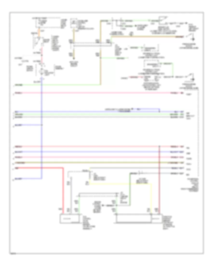
ANTI-LOCK BRAKES
Anti-Lock Brakes Wiring Diagram (1 of 2) for Acura 3.5RL 1996


List of elements for Anti-Lock Brakes Wiring Diagram (1 of 2) for Acura 3.5RL 1996:
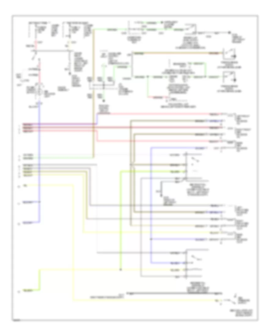
Anti-Lock Brakes Wiring Diagram (2 of 2) for Acura 3.5RL 1996
List of elements for Anti-Lock Brakes Wiring Diagram (2 of 2) for Acura 3.5RL 1996:
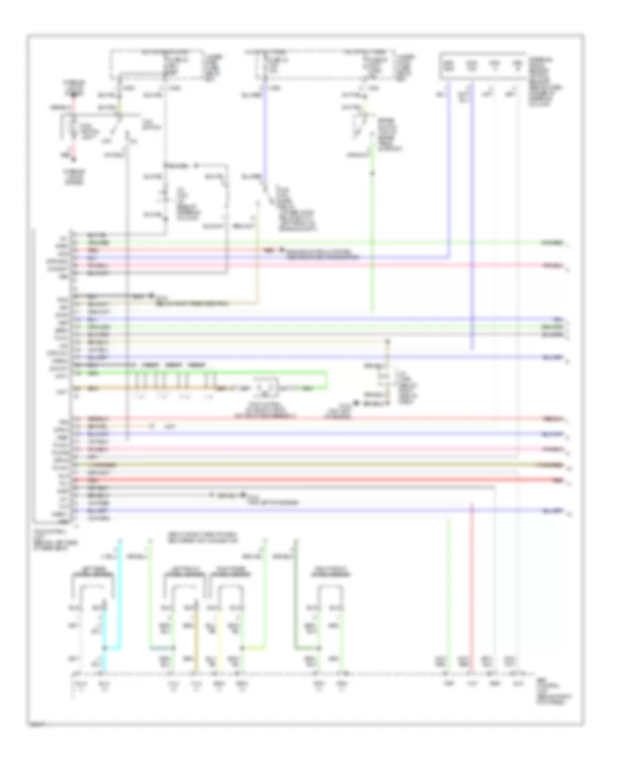
Traction Control Wiring Diagram (1 of 2) for Acura 3.5RL 1996
List of elements for Traction Control Wiring Diagram (1 of 2) for Acura 3.5RL 1996:
Traction Control Wiring Diagram (2 of 2) for Acura 3.5RL 1996
List of elements for Traction Control Wiring Diagram (2 of 2) for Acura 3.5RL 1996: