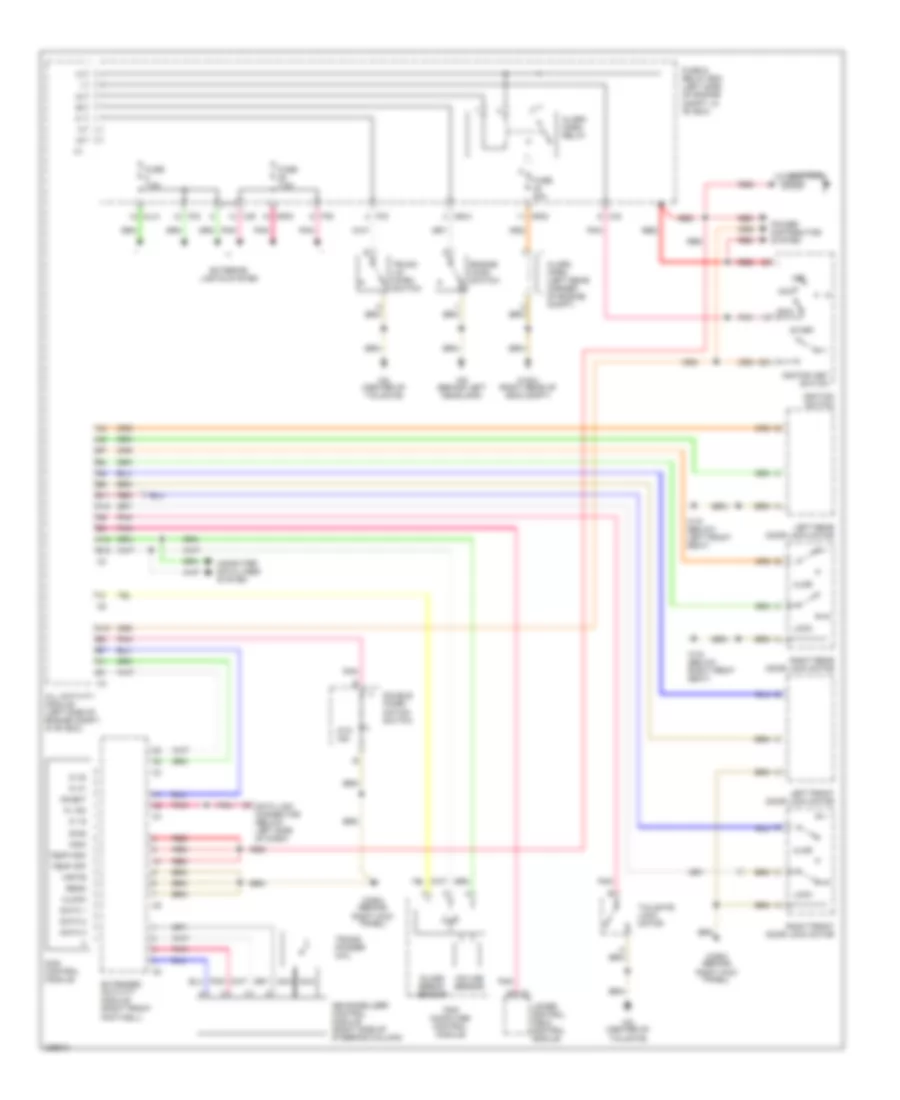
ANTI-THEFT
Anti-theft Wiring Diagram for Mercedes-Benz ML500 2003
 https://portal-diagnostov.com/license.html
Automotive Electricians Portal FZCO
Automotive Electricians Portal FZCO
https://portal-diagnostov.com/license.html
https://portal-diagnostov.com/license.html
Automotive Electricians Portal FZCO
Automotive Electricians Portal FZCO
List of elements for Anti-theft Wiring Diagram for Mercedes-Benz ML500 2003:
- 15c
- A10
- A12
- Acc
- Ajar
- Alarm horn (left rear corner of engine compt)
- Alarm horn relay
- All activity module (left side of engine compt, in "e" box)
- Ata ind
- B11
- B12
- Battery
- C/d
- C/e
- Clock
- Computer data lines system
- Das control module
- Data 1
- Data 2
- Data 3
- Data link connector (below left side of dash)
- Diag
- Double combi- nation switch
- Engine hood switch
- Extended activity module (right front footwell)
- Exterior lights system
- Fuse & relay box (left side of engine compt, in "e" box)
- Fuse 20a
- Fuse 7.5a
- Glass break sensor
- Ignition key switch
- Ignition switch
- Immo
- Incline sensor
- Inhibit
- Ki 15
- Ki 15c
- Ki 30
- Ki 31
- Left front door lock motor
- Left rear door lock motor
- Lock
- Lower control field control module
- Mb-immobilizer control module (right side of steering column)
- Ml/a
- Mr/a
- Mr/d
- Nca
- Off
- P/d
- P/e
- Pnk
- Power distribution system
- Read
- Red
- Right front door lock motor
- Right kick panel)
- Right rear door lock motor
- Run
- Start
- Tailgate lock motor
- Temp ksk
- Temp off
- Trans- ponder coil
- Trip computer control module
- Trunk lid micro switch
- W16/4 (right rear of eng compt)
- W18 (below left front seat)
- W19 (below right front seat)
- W29/2 (behind
- W8 (center of tailgate)
- W9 (behind left headlamp)
- Write
 Čeština
 Dansk
Dansk Deutsch
 Ελληνικά
 English
 English
 Español
 Suomi
Suomi Français
 Français
 עברית
עברית Hrvatski
 Magyar
 Italiano
 日本語
日本語 Nederlands
 Polski
 Português
 Português
 Română
 Русский
 Slovenčina
 Slovenščina
 Svenska
 Türkçe
 中文 (中国)
 한국어
한국어
