Čeština
 Dansk
Dansk Deutsch
 Ελληνικά
 English
 English
 Español
 Suomi
Suomi Français
 Français
 עברית
עברית Hrvatski
 Magyar
 Italiano
 日本語
日本語 Nederlands
 Polski
 Português
 Português
 Română
 Русский
 Slovenčina
 Slovenščina
 Svenska
 Türkçe
 中文 (中国)

СИСТЕМА УПРАВЛЕНИЯ ДВИГАТЕЛЯ
1.8L
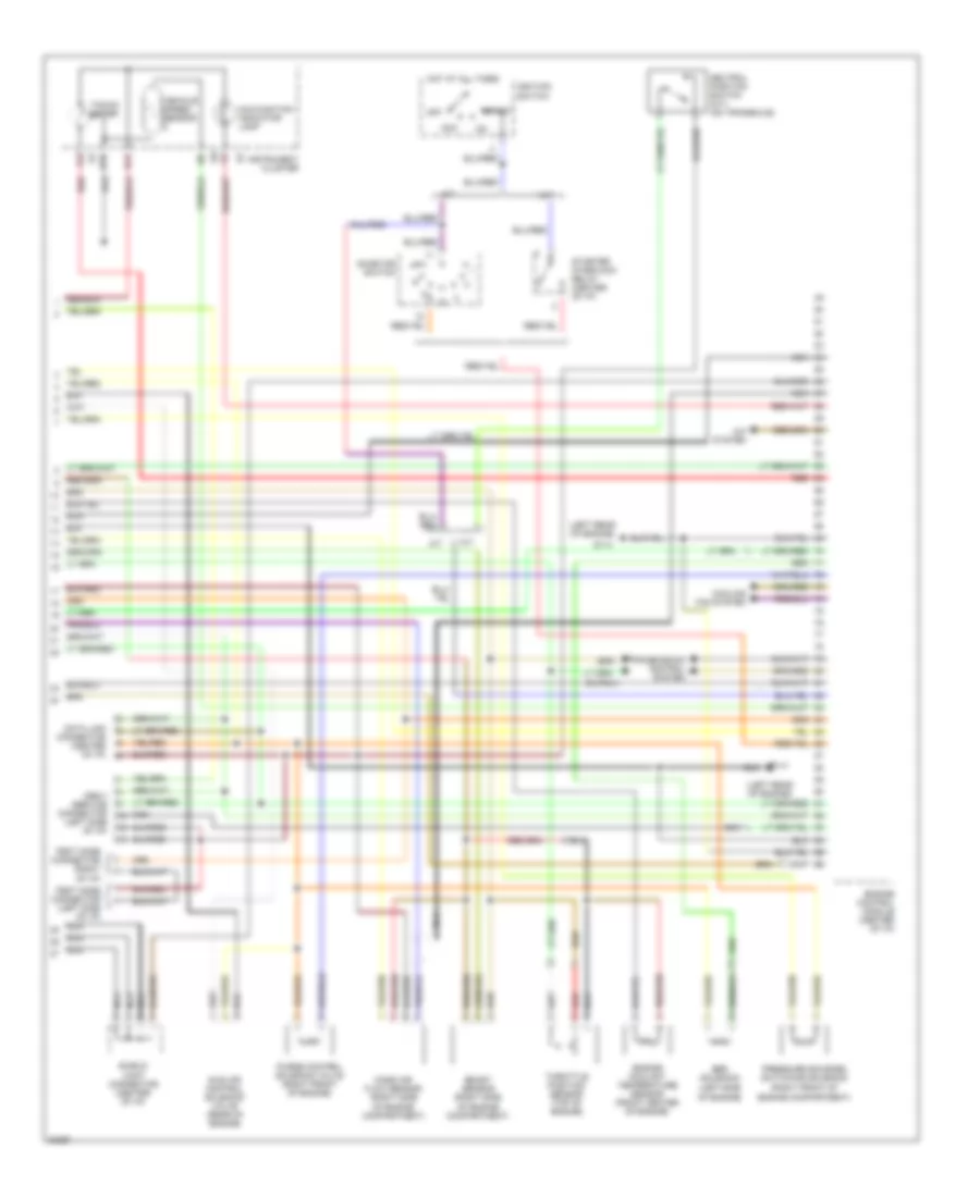
1.8L, Электросхема системы управления двигателя (1 из 2) для Subaru Impreza Brighton 1996


1.8L, Электросхема системы управления двигателя (1 из 2) для Subaru Impreza Brighton 1996 - Список элементов:
1.8L, Электросхема системы управления двигателя (2 из 2) для Subaru Impreza Brighton 1996
1.8L, Электросхема системы управления двигателя (2 из 2) для Subaru Impreza Brighton 1996 - Список элементов:
2.2L
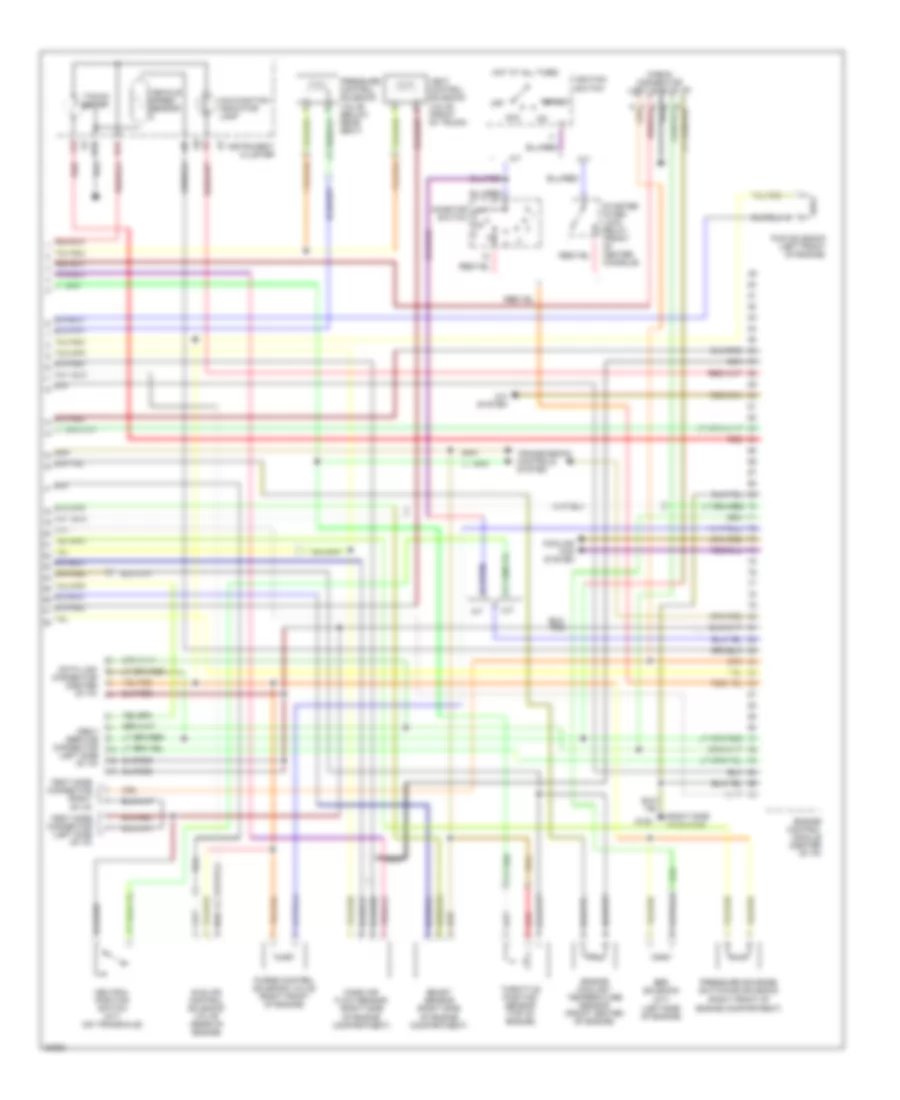
2.2L, Электросхема системы управления двигателя (1 из 2) для Subaru Impreza Brighton 1996
2.2L, Электросхема системы управления двигателя (1 из 2) для Subaru Impreza Brighton 1996 - Список элементов:
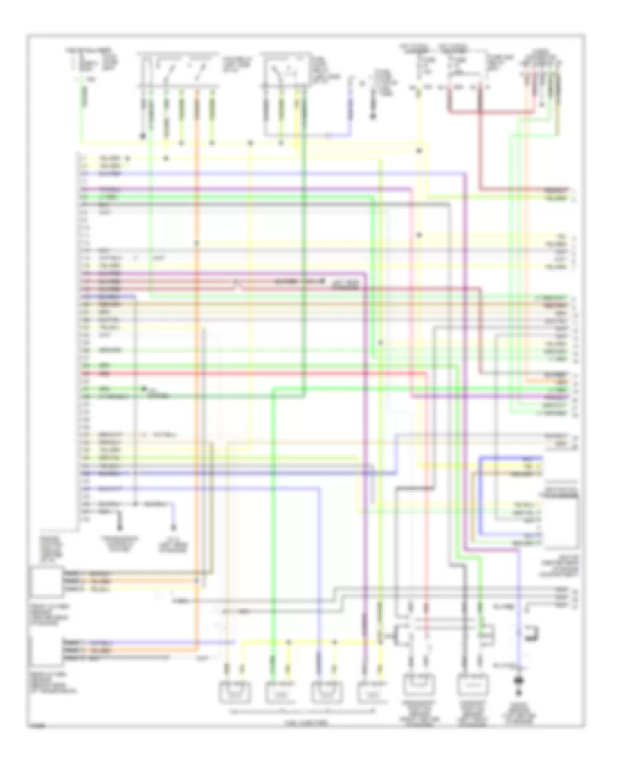
2.2L, Электросхема системы управления двигателя (2 из 2) для Subaru Impreza Brighton 1996
2.2L, Электросхема системы управления двигателя (2 из 2) для Subaru Impreza Brighton 1996 - Список элементов: