ENGINE PERFORMANCE
4.6L TURBO
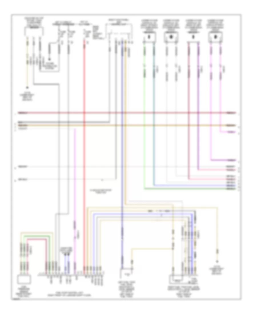
4.6L Turbo, Engine Performance Wiring Diagram (1 of 6) for Mercedes-Benz GL450 2014
 https://portal-diagnostov.com/license.html
Automotive Electricians Portal FZCO
Automotive Electricians Portal FZCO
https://portal-diagnostov.com/license.html
https://portal-diagnostov.com/license.html
Automotive Electricians Portal FZCO
Automotive Electricians Portal FZCO
List of elements for 4.6L Turbo, Engine Performance Wiring Diagram (1 of 6) for Mercedes-Benz GL450 2014:
- +5v
- 25/2-c1
- A-a-sam
- A-s-hr
- Aav
- Accelerator pedal sensor (part of accelerator pedal assembly)
- Activated charcoal filter shutoff valve (front of left front wheelwell)
- Battery compartment prefuse box (under front passenger's seat)
- Can b h
- Can b l
- Can c h
- Can c l
- Can e1 h
- Can e1 l
- Check engine mil indicator
- Circuit 87m relay
- Computer data lines system
- Coolant run-on pump
- Coolant run-on pump relay
- Coolant temperature gauge
- Coolant temperature warning lamp indicator
- Cooling fans system
- Crash
- E-a-dst
- Ekpr
- Engine compartment fuse & relay module (right side of engine compt)
- Engine diagnosis indicator lamp
- Fuel level indicator lamp
- Fuel reserve indicator lamp
- Fuel tank pressure sensor (inside fuel tank)
- Function
- Fuse 15a
- Fuse 20a
- Fuse 40a
- Fuse 7.5a
- Hot at all times
- Instrument cluster
- Llkr
- Lpv
- Lues
- Me-sfi (me) control unit (top center rear of engine)
- Mr2
- Pnk
- Power distribution system
- Purge control valve (left side of engine compt)
- S13
- Sewf 3
- Sig-htk/ntk
- Sp1s
- Sp2s
- Starting/ charging system
- Starting/charging system
- Str
- Str+
- W/ eco start/stop
- W2 (right side of engine compt)
- W52/11 (right rear of engine compt)
- X18/3-c2
- X192/1-c1
- X25/2-c1
- X25/2-c2
- X26-c1
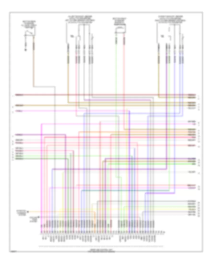
4.6L Turbo, Engine Performance Wiring Diagram (2 of 6) for Mercedes-Benz GL450 2014
 https://portal-diagnostov.com/license.html
Automotive Electricians Portal FZCO
Automotive Electricians Portal FZCO
https://portal-diagnostov.com/license.html
https://portal-diagnostov.com/license.html
Automotive Electricians Portal FZCO
Automotive Electricians Portal FZCOList of elements for 4.6L Turbo, Engine Performance Wiring Diagram (2 of 6) for Mercedes-Benz GL450 2014:
- (+)
- (-)
- (fp)
- (mounted on top of fuel tank) (if equipped) fuel quality sensor
- (right kick panel) sam control unit
- (under intake manifold, on front of left cylinder bank) knock sensor 1
- (under intake manifold, on front of right cylinder bank) knock sensor 3
- (under intake manifold, on middle of left cylinder bank) knock sensor 2
- (under intake manifold, on middle of right cylinder bank) knock sensor 4
- Can c h
- Can c l
- Computer data lines system
- Ekp
- Ekp-ec-u
- Ekp-ec-v
- Ekp-ec-w
- Ekp-sh
- Fos sig
- Fuel pressure sensor (rear of right fuel rail)
- Fuel pump control unit (right front of luggage compt floor)
- Fuel pump m
- Fuse 25a
- Fuse 5a
- Hot at all times
- Hot w/ circuit 15 relay energized
- Kds sig
- Left fuel tank fuel level indicator fill level sensor (in top of left side of fuel tank)
- Nca
- Power distribution system
- Rear fuse box (in right rear footwell)
- Red
- Right fuel tank fuel level indicator fill level sensor (in top of right side of fuel tank)
- S13
- Uh2
- W/ eco start/stop function
- W17/6 (under right seat of 2nd row)
- X18/3-c1
- X18/3-c2
- X25/2-c1
- X26-c4
- X26-c5
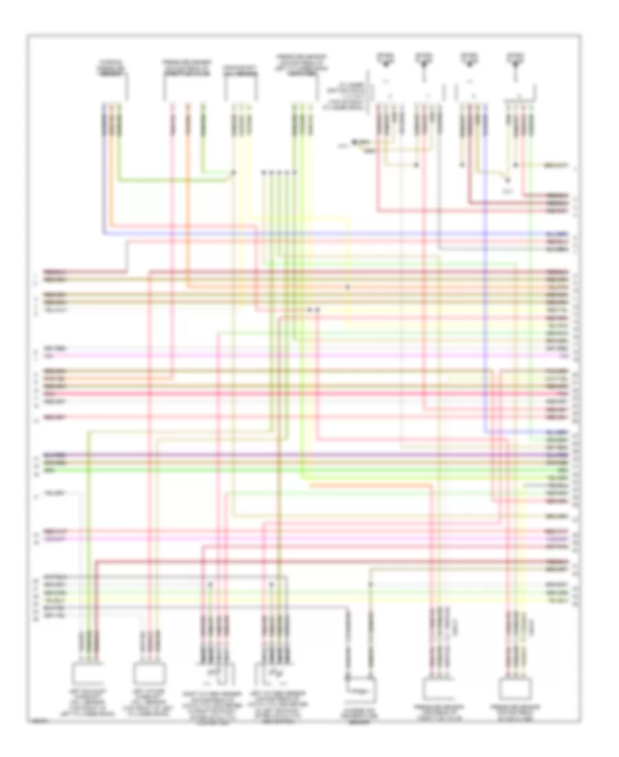
4.6L Turbo, Engine Performance Wiring Diagram (3 of 6) for Mercedes-Benz GL450 2014
 https://portal-diagnostov.com/license.html
Automotive Electricians Portal FZCO
Automotive Electricians Portal FZCO
https://portal-diagnostov.com/license.html
https://portal-diagnostov.com/license.html
Automotive Electricians Portal FZCO
Automotive Electricians Portal FZCOList of elements for 4.6L Turbo, Engine Performance Wiring Diagram (3 of 6) for Mercedes-Benz GL450 2014:
- (-)
- (bottom front of engine) engine oil pump valve
- (bottom rear of engine) oil level check switch
- (in left exhaust, before catalytic converter) left oxygen sensor upstream of catalytic converter
- (in right exhaust, before catalytic converter) right oxygen sensor upstream of catalytic converter
- Cooling fans system
- Inj h
- Inj l
- Ks m
- Kss
- Kwg
- Lin c1
- Lsh2hk
- Lsh2vk
- Lshvk1
- Lsu1ia
- Lsu1ip
- Lsu1un
- Lsu1vm
- Lsu2ia
- Lsu2ip
- Lsu2un
- Lsu2vm
- Me-sfi (me) control unit (top center rear of engine)
- Mot
- Nca
- Nwae2
- Nwga1
- Nwge1
- Nwge2
- Nwse1
- Oss
- Pnk
- Ref1
- Sig
- Starting/ charging system
- Tansv
- Tmot
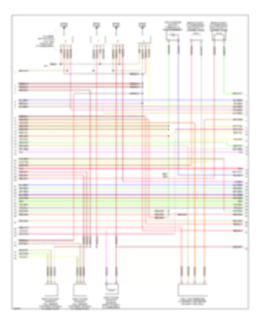
4.6L Turbo, Engine Performance Wiring Diagram (4 of 6) for Mercedes-Benz GL450 2014
 https://portal-diagnostov.com/license.html
Automotive Electricians Portal FZCO
Automotive Electricians Portal FZCO
https://portal-diagnostov.com/license.html
https://portal-diagnostov.com/license.html
Automotive Electricians Portal FZCO
Automotive Electricians Portal FZCOList of elements for 4.6L Turbo, Engine Performance Wiring Diagram (4 of 6) for Mercedes-Benz GL450 2014:
- Charge air temperature sensor
- Crankshaft hall sensor
- Cylinder ignition coils 1, 2, 3 & 4 (top of right cylinder bank)
- Left exhaust camshaft hall sensor (top front of left cylinder bank)
- Left intake camshaft hall sensor (top front of left cylinder bank)
- Left oxygen sensor downstream of catalytic converter (in left exhaust, after catalytic converter)
- Nca
- Pnk
- Pressure sensor downstream of air filter
- Pressure sensor downstream of left cylinder bank air filter
- Pressure sensor downstream of throttle valve
- Pressure sensor upstream of throttle valve
- Purging pressure sensor
- Right oxygen sensor downstream of catalytic converter (in right exhaust, after catalytic converter)
- Spark plugs
- W11
- X26-c3
- X26-c8
4.6L Turbo, Engine Performance Wiring Diagram (5 of 6) for Mercedes-Benz GL450 2014
 https://portal-diagnostov.com/license.html
Automotive Electricians Portal FZCO
Automotive Electricians Portal FZCO
https://portal-diagnostov.com/license.html
https://portal-diagnostov.com/license.html
Automotive Electricians Portal FZCO
Automotive Electricians Portal FZCOList of elements for 4.6L Turbo, Engine Performance Wiring Diagram (5 of 6) for Mercedes-Benz GL450 2014:
- (rear of right cylinder bank) left quantity control valve
- (rear of right cylinder bank) right quantity control valve
- (top of engine) coolant thermostat heating element
- Cylinder ignition coils 5, 6, 7 & 8 (top of left cylinder bank)
- Fuel tank pressure & temperature sensor (on right fuel rail)
- Pnk
- Right exhaust camshaft hall sensor (top front of right cylinder bank)
- Right intake camshaft hall sensor (top front of right cylinder bank)
- Right intake camshaft solenoid (front of right cylinder bank)
- Spark plugs
- W11
4.6L Turbo, Engine Performance Wiring Diagram (6 of 6) for Mercedes-Benz GL450 2014
 https://portal-diagnostov.com/license.html
Automotive Electricians Portal FZCO
Automotive Electricians Portal FZCO
https://portal-diagnostov.com/license.html
https://portal-diagnostov.com/license.html
Automotive Electricians Portal FZCO
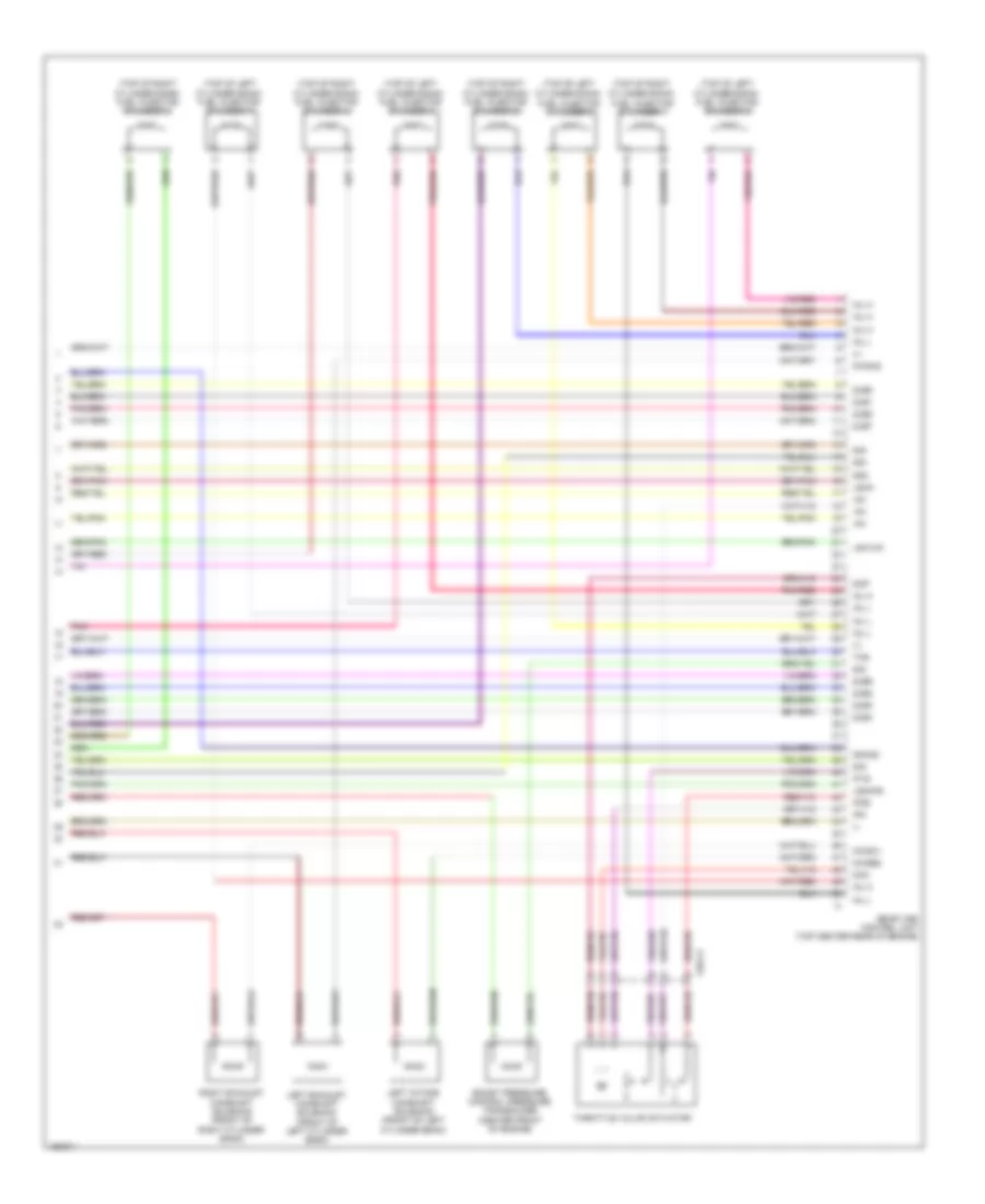
Automotive Electricians Portal FZCOList of elements for 4.6L Turbo, Engine Performance Wiring Diagram (6 of 6) for Mercedes-Benz GL450 2014:
- (+)
- (-)
- (top of left cylinder bank)
- (top of left cylinder bank) fuel injector cylinder 5
- (top of left cylinder bank) fuel injector cylinder 6
- (top of left cylinder bank) fuel injector cylinder 7
- (top of right cylinder bank)
- (top of right cylinder bank) fuel injector cylinder 2
- (top of right cylinder bank) fuel injector cylinder 3
- (top of right cylinder bank) fuel injector cylinder 4
- +5v
- Boost pressure control pressure transducer (center front of engine)
- Dcm
- Dcp
- Ds1
- Ds2
- Fuel injector cylinder 1
- Fuel injector cylinder 8
- Gnag2
- Inj h
- Inj l
- Ip1s
- Ip2s
- Ipm
- Left exhaust camshaft solenoid (front of left cylinder bank)
- Left intake camshaft solenoid (front of left cylinder bank)
- Ls2hks
- Lsh1hk
- Lshk
- Me-sfi (me) control unit (top center rear of engine)
- Nwsa1
- Nwsa2
- Nwse2
- Pnk
- Pnk/red
- Right exhaust camshaft solenoid (front of right cylinder bank)
- Sig
- Throttle valve actuator
- Ths
- X26-c3
- Zue1
- Zue2
- Zue3
- Zue4
- Zue5
- Zue6
- Zue7
- Zue8

 Čeština
 Dansk
Dansk Deutsch
 Ελληνικά
 English
 English
 Español
 Suomi
Suomi Français
 Français
 עברית
עברית Hrvatski
 Magyar
 Italiano
 日本語
日本語 Nederlands
 Polski
 Português
 Português
 Română
 Русский
 Slovenčina
 Slovenščina
 Svenska
 Türkçe
 中文 (中国)
