POWER DISTRIBUTION
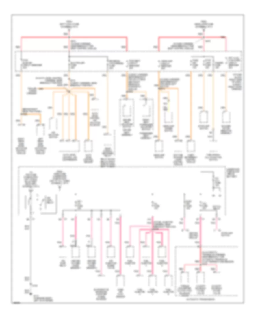
Power Distribution Wiring Diagram (1 of 4) for Chevrolet Venture 2005
 https://portal-diagnostov.com/license.html
Automotive Electricians Portal FZCO
Automotive Electricians Portal FZCO
https://portal-diagnostov.com/license.html
https://portal-diagnostov.com/license.html
Automotive Electricians Portal FZCO
Automotive Electricians Portal FZCO
List of elements for Power Distribution Wiring Diagram (1 of 4) for Chevrolet Venture 2005:
- (diagram 1 of 4)
- (diagram 2 of 4)
- (diagram 3 of 4)
- (in body harness, at left rear wheelwell) s326
- (in dash harness, near breakout for cigar lighter)
- (in dash harness, near breakout for window wiper/washer & multifunction switch)
- (in i/p harness, near blower motor resistor breakout) s212
- Air fuse 30a
- Air pump relay
- Alt/ sense fuse 10a
- B/u lamp fuse 10a
- Batt main 1 fuse 60a
- Batt main 2 fuse 60a
- Battery
- Body control module
- Cigar lighter
- Cigar/dlc/ apo frt fuse 20a
- Cluster batt fuse 10a
- Cool fan 1 fuse 30a
- Cool fan 1 relay
- Cool fan 2 fuse 30a
- Cool fan 2 relay
- Cool fan relay
- Ctsy lamp fuse 10a
- Data link connector
- Daytime running lamps control module
- Digital radio receiver (if equipped)
- Driver information center (dic)
- E12
- E16
- Ecm sense fuse 10a
- Electronic brake control module
- Fog lamp relay
- Fog lp fuse 10a
- From radio fuse a
- Front auxiliary power outlet
- Fuel pump fuse 15a
- Fuel pump relay
- Fusible link a (10ga- rust)
- G200 (at right side of dash)
- G401 (at lower left "d" pillar)
- Generator
- Head- lamps fuse 60a
- Headlamp switch
- Horn fuse 15a
- Horn relay
- Hvac control assembly
- I/p fuse block (right side of dash, in right front door opening)
- Ign main 1 fuse 40a
- Ign main 2 fuse 60a
- Ign main relay (diagram 2 of 4)
- Instrument panel cluster (ipc)
- Left rear slide door actuator control module
- Onstar fuse 5a
- Outside rearview mirror switch
- Overhead console
- Park lp fuse 20a
- Park/ neutral position switch
- Powertrain control module
- Pwr lock fuse 20a
- Pwr mirror fuse 10a
- Radio
- Radio fuse 10a
- Rap relay fuse 10a
- Rear auxiliary power outlet
- Red
- Remote control door lock receiver
- Right rear slide door actuator control module
- Rr pwr sckt fuse 20a
- S202
- S213
- S238
- S276 (in dash harness, near breakout for body control module)
- S403
- Starter
- Starter relay
- Theft led
- To cool fan 1 fuse (diagram 1 of 4)
- To ignition switch pin d2
- To ignition switch pin d5
- To rap relay (diagram 4 of 4)
- To s274
- To s278
- Underhood fuse block (above battery)
- Vehicle interface unit (viu)
- Video disc player (if equipped)
- W/ power sliding door
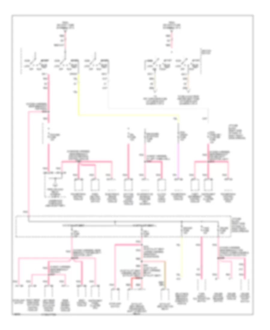
Power Distribution Wiring Diagram (2 of 4) for Chevrolet Venture 2005
 https://portal-diagnostov.com/license.html
Automotive Electricians Portal FZCO
Automotive Electricians Portal FZCO
https://portal-diagnostov.com/license.html
https://portal-diagnostov.com/license.html
Automotive Electricians Portal FZCO
Automotive Electricians Portal FZCOList of elements for Power Distribution Wiring Diagram (2 of 4) for Chevrolet Venture 2005:
- (behind right rear trim panel) s322
- (diagram 1 of 4)
- (in auto level control harness, near breakout for p403) s445
- (in automatic transaxle harness, near breakout for automatic transaxle fluid temperature sensor) s115
- (in dash harness, near breakout for body control module)
- (in fuel injector pnk
- 1-2 shift solenoid (1-2 ss) valve
- 2-3 shift solenoid (2-3 ss) valve
- A/c clu fuse 10a
- A/c clu relay
- A12
- Air inflator switch
- Air injection bleed valve
- Air pump relay
- Auto level control air compressor
- Auto level control air inflator solenoid
- Auto level control sensor
- Automatic transmission
- Blower motor resistor assembly
- Daytime running lamps control module
- Driver seat adjuster switch
- Driver seat assembly
- E10
- Elc/trailer fuse 25a
- Elek ign fuse 15a
- Evaporative emissions canister purge solenoid
- From batt main 2 fuse
- From headlamps fuse
- From horn fuse (underhood fuse block) (hot at all times) (diagram 1 of 4)
- Front seat passenger adjuster switch
- Frt hvac hi blower circuit breaker 30a
- Fuel injector
- G113 (in engine compt, left of starter)
- Harness, near breakout for c102) s109
- Hazard fuse 15a
- Headlamp circuit breaker 20a
- Headlamp dimmer switch
- Headlamp switch
- Heated oxygen (ho2s) sensor 1
- Heated oxygen (ho2s) sensor 2
- I/p fuse block (right side of dash, in right front door opening)
- Ign 1 u/h fuse 15a
- Ign main relay
- Ignition control module
- Inj fuse 10a
- Left rear side door actuator control module
- Mass air flow sensor
- Nca
- Near breakout for inflatable restraint sensing & diagnostic module) s302
- Pass key fuse 10a
- Passenger seat assembly
- Pnk
- Pwr seat circuit breaker 30a
- Pwr sldg dr circuit breaker 30a
- Rear window defogger relay
- Red
- Relay block (below right side of dash, next to bcm)
- Right rear side door actuator control module
- Rr defog/ htd mirrors fuse 30a
- S106
- S274 (in dash harness, near breakout for body control module)
- S278
- S412 (in body harness, near breakout for p401)
- Stop lamp fuse 15a
- Stoplamp switch
- Tcc fuse 10a
- Theft deterrent control module
- To pcm fuse (fuse block) (hot in run, bulb test or start) (diagram 3 of 4)
- Torque converter clutch (tcc) solenoid valve
- Trailer wiring harness
- Turn signal/ multifunction switch
- Underhood fuse block (above battery)
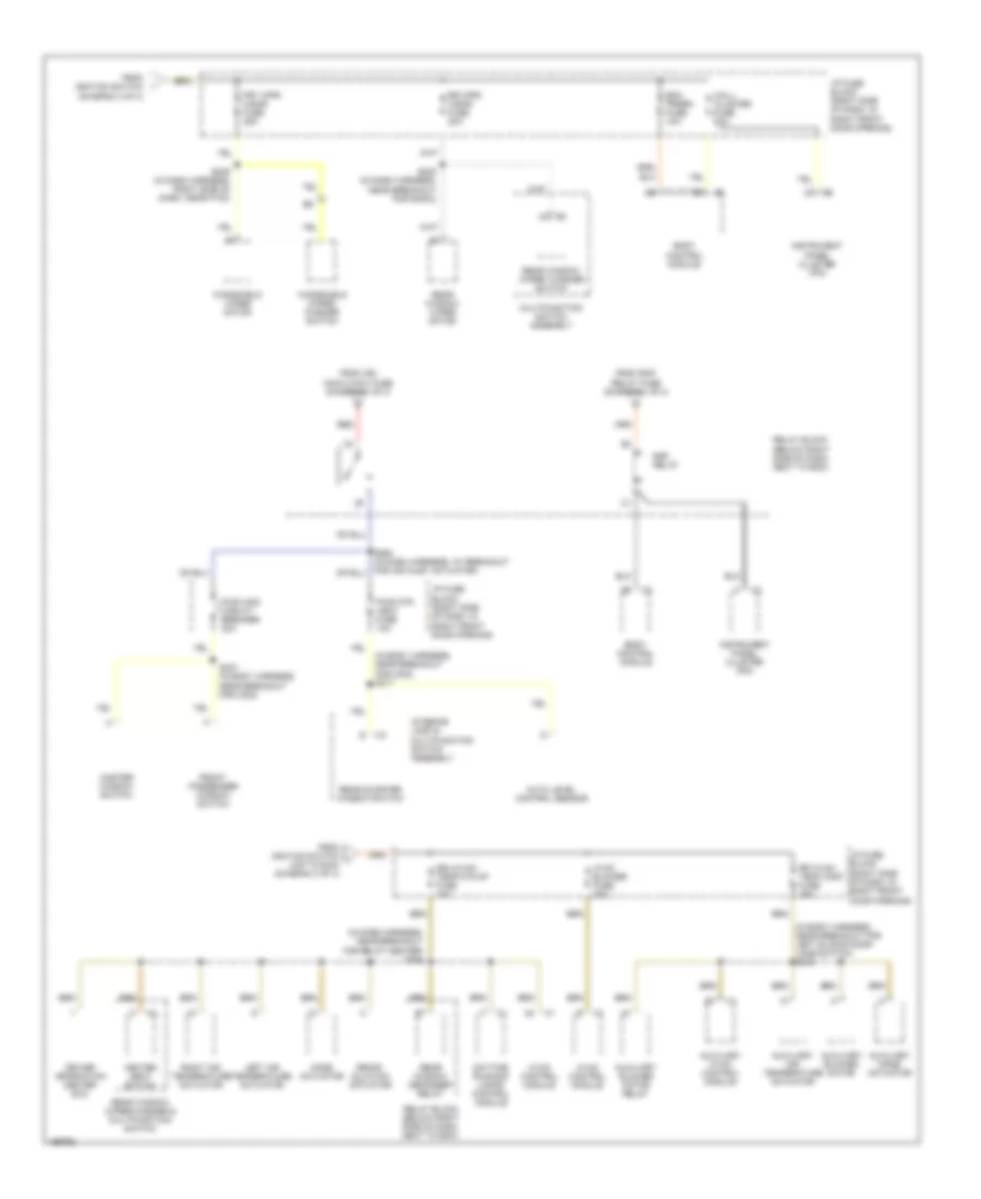
Power Distribution Wiring Diagram (3 of 4) for Chevrolet Venture 2005
 https://portal-diagnostov.com/license.html
Automotive Electricians Portal FZCO
Automotive Electricians Portal FZCO
https://portal-diagnostov.com/license.html
https://portal-diagnostov.com/license.html
Automotive Electricians Portal FZCO
Automotive Electricians Portal FZCOList of elements for Power Distribution Wiring Diagram (3 of 4) for Chevrolet Venture 2005:
- (if equipped)
- (in body harness, at left wheelwell) s391
- (in body harness, near breakout for p401) s337
- (in dash harness, near pnk breakout for security indicator light) s209
- (in dash harness, near breakout for radio) s228
- (in dash harness, near breakout for window wiper/washer & multifunction switch) s266
- (in dash harness, near breakout pnk
- (in engine harness, near breakout for powertrain control module) s108
- A10
- A11
- A13
- Acc
- Acc 1
- Below sit-n-lift seat)
- Body control module
- Bulb test
- C10
- C13
- Clutch pump check valve
- Crank
- Cruise control module
- Cruise control on/off switch
- Cruise control release switch
- Cruise fuse 10a
- D11
- Daytime running lamps control module
- Drl fuse 10a
- Electronic brake control module
- Enhanced evap/awd fuse 15a
- Evaporative emission canister vent solenoid
- For security indicator light) s210
- From ign main 1 fuse (diagram 1 of 4)
- From ign main 2 fuse (diagram 1 of 4)
- From ign main relay (diagram 2 of 4)
- I/p fuse block (right side of dash, in right front door opening)
- Ign 0
- Ign 1
- Ign 1 fuse 10a
- Ign 3
- Ignition switch
- Inflatable restraint sensing & diagnostic module
- Instrument panel cluster (ipc)
- Left rear side door actuator control module
- Lock
- Off
- Park/ neutral position switch
- Pcm/ crank fuse 10a
- Pcm/ pass key/ cluster fuse 10a
- Pcm/abs fuse 10a
- Pnk
- Powertrain control module
- Powertrain control module (pcm)
- Rear object sensor control module
- Red
- Right rear side door actuator control module
- Run
- S361 (in sit-n-lift seat harness, (in sit-n-lift seat harness, below sit-n-lift seat) s362
- S372 (in sit-n-lift seat jumper harness, near right sliding door)
- Sdm/sir fuse 15a
- Sit-n-lift seat/brake transmission shift interlock relay
- Sit-n-lift seat/ignition relay
- Start
- Stoplamp switch
- T/sig fuse 10a
- Theft deterrent control module
- To drl/hvac/temp/ heated seat fuse (i/p fuse block) (diagram 4 of 4)
- To frt wpr/wshr fuse (i/p fuse block) (diagram 4 of 4)
- Turn signal/ multifunction switch
- Underhood fuse block (above battery)
- W/ sit-n-lift seat
- W/o sit-n-lift seat
Power Distribution Wiring Diagram (4 of 4) for Chevrolet Venture 2005
 https://portal-diagnostov.com/license.html
Automotive Electricians Portal FZCO
Automotive Electricians Portal FZCO
https://portal-diagnostov.com/license.html
https://portal-diagnostov.com/license.html
Automotive Electricians Portal FZCO
Automotive Electricians Portal FZCOList of elements for Power Distribution Wiring Diagram (4 of 4) for Chevrolet Venture 2005:
- (diagram 3 of 4)
- (in body harness, near breakout for c302) s317
- (in body harness, near breakout for left sliding door jamb switch) s345
- (in dash harness, near breakout for relay center) s264
- Auto level control sensor
- Auxiliary air temperature actuator
- Auxiliary blower motor
- Auxiliary blower motor relay
- Auxiliary hvac control module
- Auxiliary mode actuator
- Bcm prgrm fuse 10a
- Body control module
- Daytime running lamps control module
- Driver information center (dic)
- Drl/hvac/ temp/htd st fuse 10a
- From ign main 2 maxi fuse (diagram 1 of 4)
- From ignition switch
- From ignition switch j (hot in run) (diagram 3 of 4)
- From rap relay fuse (diagram 1 of 4)
- Front passenger window switch
- Frt wpr/ wshr fuse 25a
- Heated seat switch
- Hvac blower fuse 25a
- Hvac control module
- I/p fuse block (right side of dash, in right front door opening)
- Instrument panel cluster (ipc)
- Interior lamp & multifunction switch assembly
- Left air temperature actuator
- Mall/ cluster fuse 10a
- Master window switch
- Mode actuator
- Multifunction switch assembly
- Pwr otr vent fuse 10a
- Pwr wdo circuit breaker 30a
- Rap relay
- Rear quarter window switch
- Rear window defogger relay
- Rear window wiper motor
- Rear window wiper/ washer switch
- Rear window wiper/washer & multifunction switch
- Recir- culation actuator
- Red
- Relay block (below right side of dash, next to bcm)
- Right air temperature actuator
- Rr hvac/ temp cont fuse 25a
- Rr wpr/ wshr fuse 20a
- S245 (in dash harness, near breakout for radio)
- S249 (in dash harness, right side of dash, near p100)
- S307 (in body harness, near breakout for c302)
- Windshield wiper motor
- Windshield wiper/ washer switch

 Čeština
 Dansk
Dansk Deutsch
 Ελληνικά
 English
 English
 Español
 Suomi
Suomi Français
 Français
 עברית
עברית Hrvatski
 Magyar
 Italiano
 日本語
日本語 Nederlands
 Polski
 Português
 Português
 Română
 Русский
 Slovenčina
 Slovenščina
 Svenska
 Türkçe
 中文 (中国)
