Čeština
 Dansk
Dansk Deutsch
 Ελληνικά
 English
 English
 Español
 Suomi
Suomi Français
 Français
 עברית
עברית Hrvatski
 Magyar
 Italiano
 日本語
日本語 Nederlands
 Polski
 Português
 Português
 Română
 Русский
 Slovenčina
 Slovenščina
 Svenska
 Türkçe
 中文 (中国)

RADIO
Auto Pilot System Wiring Diagram for Mercedes-Benz E500 4Matic 2006


List of elements for Auto Pilot System Wiring Diagram for Mercedes-Benz E500 4Matic 2006:
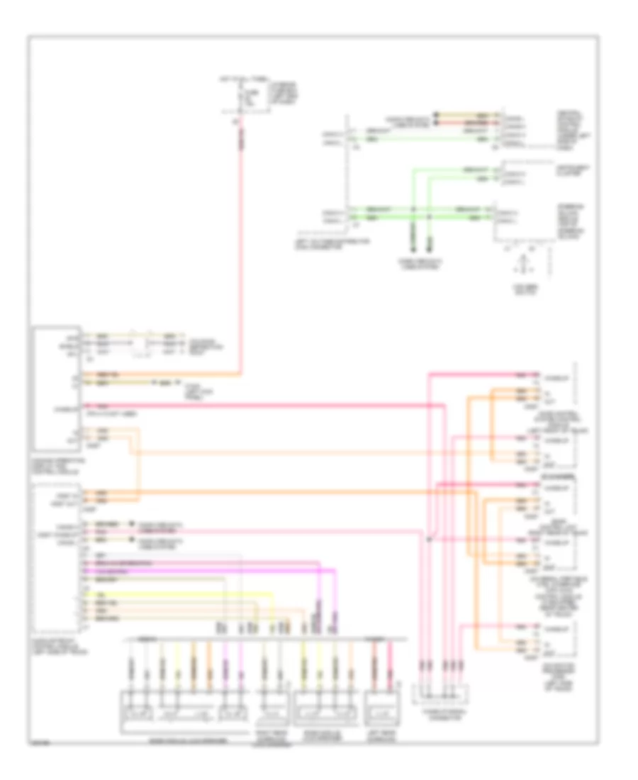
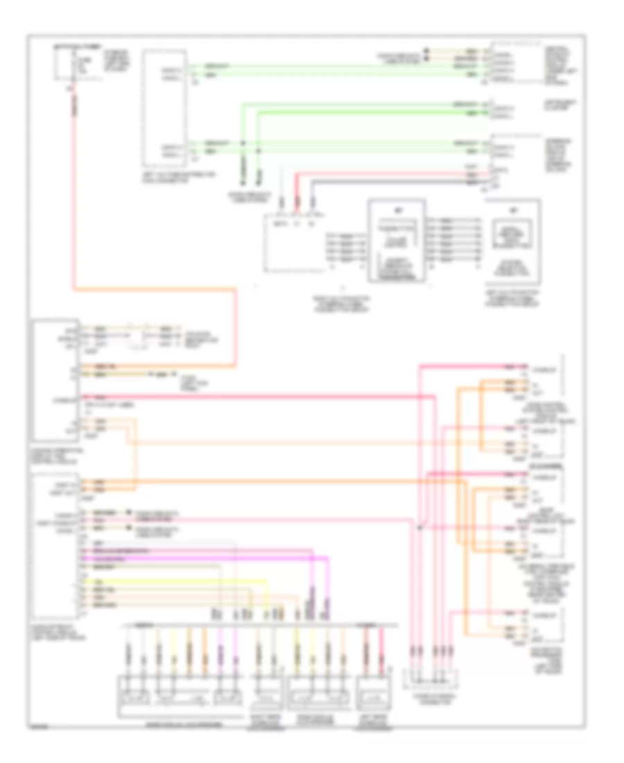
COMAND Actuation Wiring Diagram for Mercedes-Benz E500 4Matic 2006
List of elements for COMAND Actuation Wiring Diagram for Mercedes-Benz E500 4Matic 2006:
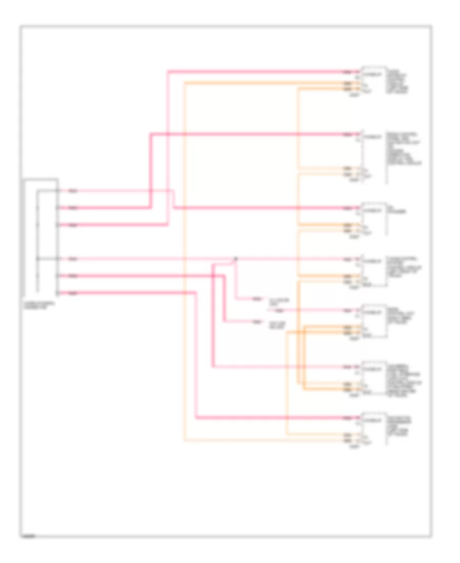
MOST Data Bus Wiring Diagram for Mercedes-Benz E500 4Matic 2006
List of elements for MOST Data Bus Wiring Diagram for Mercedes-Benz E500 4Matic 2006:
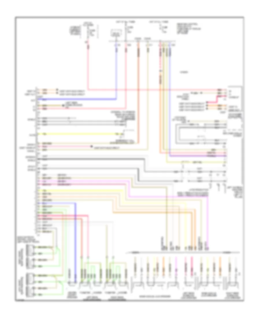
Radio Wiring Diagram for Mercedes-Benz E500 4Matic 2006
List of elements for Radio Wiring Diagram for Mercedes-Benz E500 4Matic 2006:
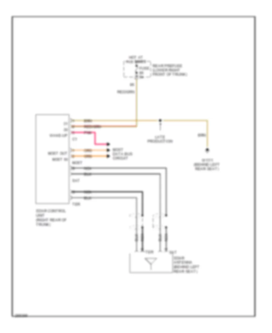
Satellite Radio Wiring Diagram for Mercedes-Benz E500 4Matic 2006
List of elements for Satellite Radio Wiring Diagram for Mercedes-Benz E500 4Matic 2006:
Voice Activation Wiring Diagram for Mercedes-Benz E500 4Matic 2006
List of elements for Voice Activation Wiring Diagram for Mercedes-Benz E500 4Matic 2006: