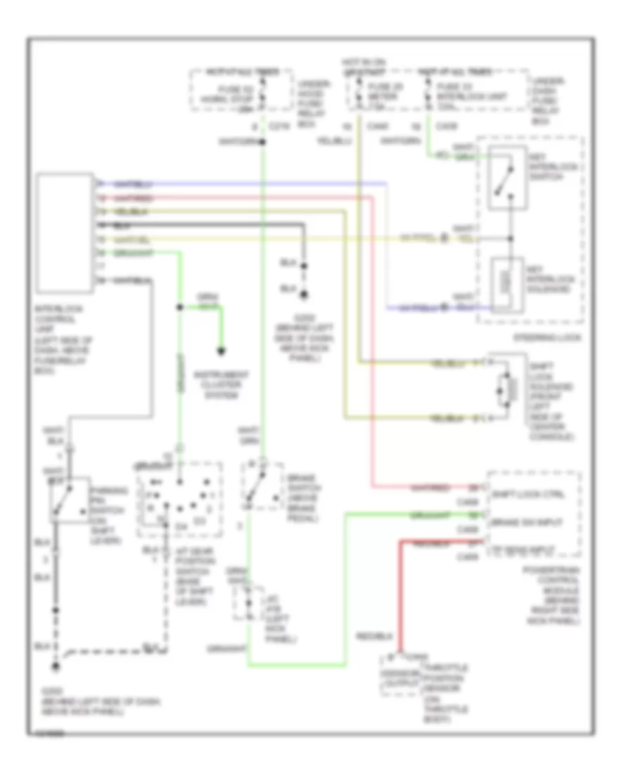
SHIFT INTERLOCK
Shift Interlock Wiring Diagram for Acura Integra LS 2001
 https://portal-diagnostov.com/license.html
Automotive Electricians Portal FZCO
Automotive Electricians Portal FZCO
https://portal-diagnostov.com/license.html
https://portal-diagnostov.com/license.html
Automotive Electricians Portal FZCO
Automotive Electricians Portal FZCO
List of elements for Shift Interlock Wiring Diagram for Acura Integra LS 2001:
- (left side of dash, above fuse/relay box)
- (on throttle body)
- A/t gear position switch (base of shift lever)
- Brake sw input
- Brake switch (above brake pedal)
- C115
- C216
- C408
- C409
- C439
- C440
- Fuse 25 meter 7.5a
- Fuse 33 interlock unit 7.5a
- Fuse 52 horn, stop 20a
- G202 (behind left side of dash, above kick panel)
- Hot at all times
- Hot in on or start
- Instrument cluster system
- Interlock control unit
- J/c (left kick panel)
- Key interlock solenoid
- Key interlock switch
- Parking pin switch (on shift lever)
- Powertrain control module (behind right side kick panel)
- Sensor output
- Shift lock ctrl
- Shift lock solenoid (front left side of center console)
- Steering lock
- Throttle position sensor
- Tp sens input
- Under- dash fuse/ relay box
- Under- hood fuse/ relay box
 Čeština
 Dansk
Dansk Deutsch
 Ελληνικά
 English
 English
 Español
 Suomi
Suomi Français
 Français
 עברית
עברית Hrvatski
 Magyar
 Italiano
 日本語
日本語 Nederlands
 Polski
 Português
 Português
 Română
 Русский
 Slovenčina
 Slovenščina
 Svenska
 Türkçe
 中文 (中国)
 한국어
한국어
