Čeština
 Dansk
Dansk Deutsch
 Ελληνικά
 English
 English
 Español
 Suomi
Suomi Français
 Français
 עברית
עברית Hrvatski
 Magyar
 Italiano
 日本語
日本語 Nederlands
 Polski
 Português
 Português
 Română
 Русский
 Slovenčina
 Slovenščina
 Svenska
 Türkçe
 中文 (中国)

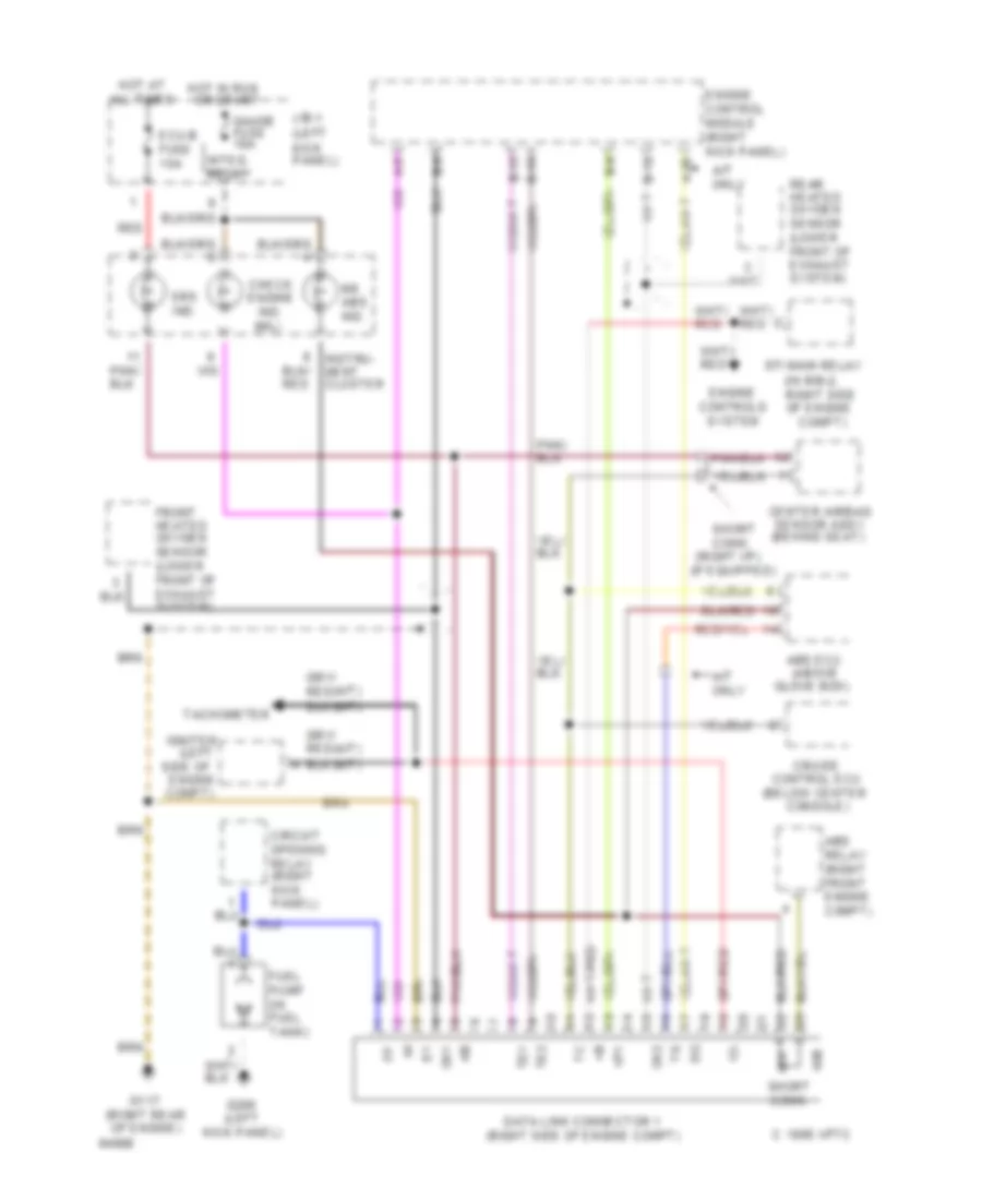
COMPUTER DATA LINES
2.7L
2.7L, Data Link Connector Wiring Diagram for Toyota T100 SR5 1994


List of elements for 2.7L, Data Link Connector Wiring Diagram for Toyota T100 SR5 1994:
3.0L
3.0L, Data Link Connector Wiring Diagram for Toyota T100 SR5 1994
List of elements for 3.0L, Data Link Connector Wiring Diagram for Toyota T100 SR5 1994: