ENGINE PERFORMANCE
2.2L
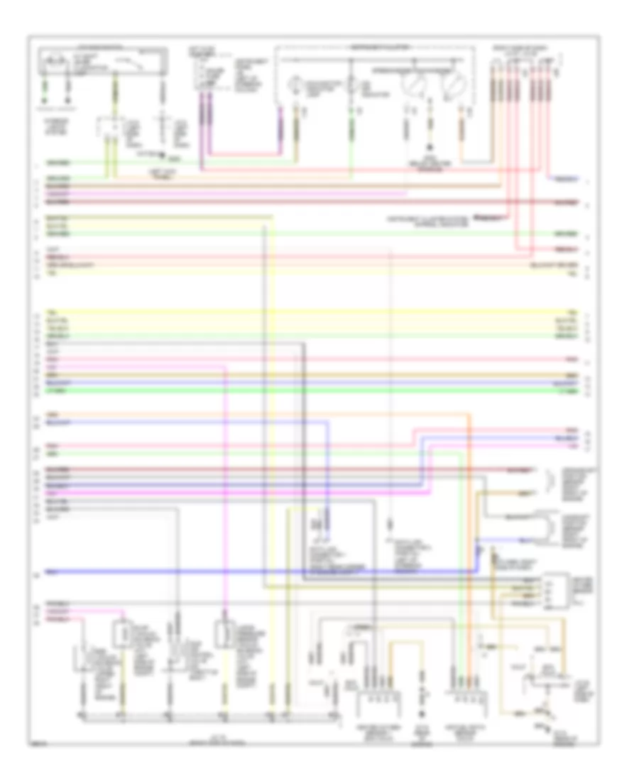
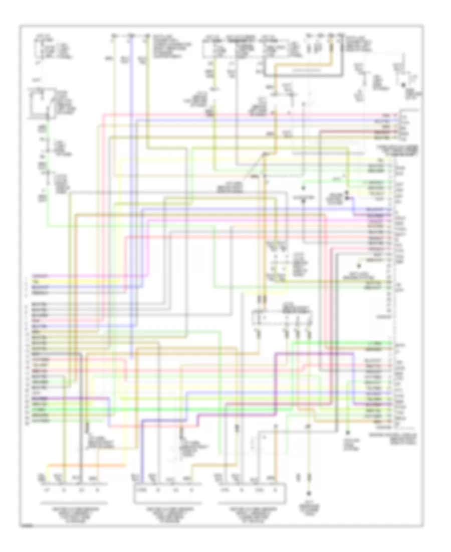
2.2L, Engine Performance Wiring Diagrams (1 of 3) for Toyota Camry CE 1997
 https://portal-diagnostov.com/license.html
Automotive Electricians Portal FZCO
Automotive Electricians Portal FZCO
https://portal-diagnostov.com/license.html
https://portal-diagnostov.com/license.html
Automotive Electricians Portal FZCO
Automotive Electricians Portal FZCO
List of elements for 2.2L, Engine Performance Wiring Diagrams (1 of 3) for Toyota Camry CE 1997:
- (a/t)
- (behind left headlamp) g106
- (calif)
- (eng harn, left front fender)
- (exc calif)
- (left side of dash)
- (left side of engine)
- (right side of dash)
- (right side of dash) j/c 27, j/c 28
- A j27
- A/c sw
- A/c system
- Acc
- Af+/ox1
- Af-
- Am2
- B j27
- Batt
- C j28
- C10
- Conn e7
- Conn e8
- Conn e9
- Cruise control system
- Defogger system
- E01
- E02
- E03
- E04
- Efi fuse 15a
- Efi relay
- Egr
- Els
- Engine control module (behind blove box)
- Engine room r/b 2 (left side of engine compt)
- Evp
- Exterior lights system
- Fuel injector
- G115 (rear of engine)
- Gnd
- Hot at all times
- Ht1
- Ht2
- Htaf
- I2 (i/p harn, behind glove blox)
- Idle-up diode (right side of dash taped to harn)
- Idlo
- Ig2
- Igf
- Ign fuse 5a
- Ignition coil/ igniter 1
- Ignition coil/ igniter 2
- Ignition switch
- Igt
- Igt1
- Igt2
- Instrument panel j/b (left of steering column)
- Iscc
- Isco
- J/c 1
- J/c 15 (top center of dash)
- J/c 19 (right side of dash)
- J/c 21
- J/c 23 (right side of dash)
- J/c 25 (right side of dash)
- Knk
- Knock sensor (front of engine)
- Lock
- Lock in
- Mgc
- Ne+
- Ne-
- Nsw
- Od1
- Od2
- Ox2
- Pim
- Pnk
- Power steering oil pressure switch (right rear of engine)
- Prs
- Ps sw
- Ptnk
- Red
- Sil
- Spd
- Sta
- Start
- Starting/ charging system
- Starting/charging system
- Stop fuse 15a
- Stop light switch
- Stp
- Tach
- Te1
- Tha
- Thr
- Thw
- Tpc
- Vta
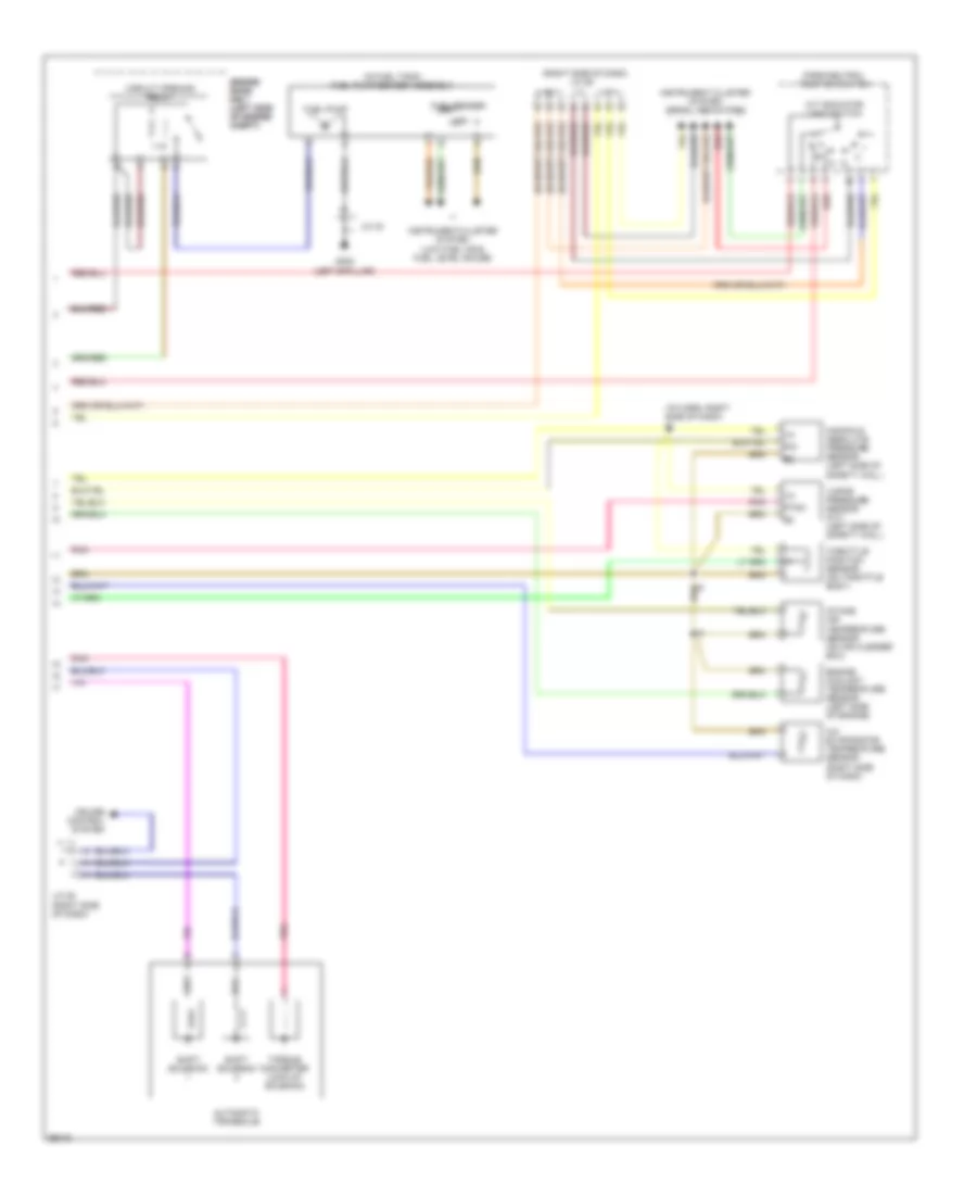
2.2L, Engine Performance Wiring Diagrams (2 of 3) for Toyota Camry CE 1997
 https://portal-diagnostov.com/license.html
Automotive Electricians Portal FZCO
Automotive Electricians Portal FZCO
https://portal-diagnostov.com/license.html
https://portal-diagnostov.com/license.html
Automotive Electricians Portal FZCO
Automotive Electricians Portal FZCOList of elements for 2.2L, Engine Performance Wiring Diagrams (2 of 3) for Toyota Camry CE 1997:
- (left kick panel)
- (right side of dash) j/c 27, j/c 28
- A/t shift lever illumination lamp
- Af+
- Af-
- Air fuel ratio sensor (calif)
- C j27
- C10
- Calif
- Camshaft position sensor (right front of engine)
- Crankshaft position sensor (right front of engine)
- Data link connector 1 (partial) (right rear corner of engine compt)
- Data link connector 3 (partial) (left of steering column)
- Egr vacuum solenoid valve (upper right front of engine)
- Evap vacuum solenoid valve (a/t) (left side of engine compt)
- Exc calif
- F j28
- G115 (rear of engine)
- G200
- G302 (below center console)
- Gauge fuse 10a
- Heated oxygen sensor (all)
- Heated oxygen sensor 1 (exc calif)
- Hot in on or start
- Idle air control valve (on throttle body)
- Instrument cluster
- Instrument cluster system (r-prndl indicator)
- Instrument panel j/b (left of steering column)
- Interior lights system
- J/c 19 (right side of dash)
- J/c 23 (left side of dash)
- J/c 5 (left side of dash)
- J/c 6 (left side of dash)
- Malfunction indicator lamp
- O/d main switch
- O/d off indicator
- Pnk
- Speedometer
- Tachometer
- Vapor pressure sensor vacuum solenoid valve (a/t) (left side of engine compt)
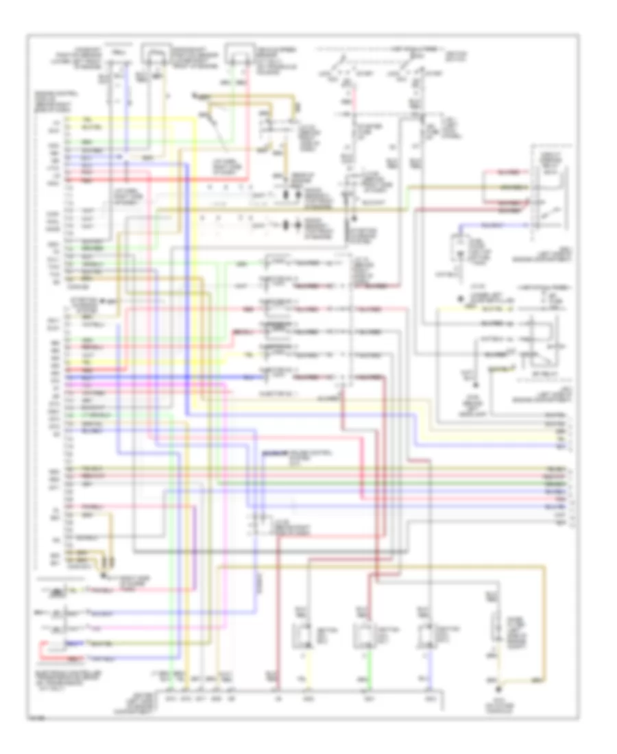
2.2L, Engine Performance Wiring Diagrams (3 of 3) for Toyota Camry CE 1997
 https://portal-diagnostov.com/license.html
Automotive Electricians Portal FZCO
Automotive Electricians Portal FZCO
https://portal-diagnostov.com/license.html
https://portal-diagnostov.com/license.html
Automotive Electricians Portal FZCO
Automotive Electricians Portal FZCOList of elements for 2.2L, Engine Performance Wiring Diagrams (3 of 3) for Toyota Camry CE 1997:
- (i/p harn, right side of dash) i2
- (in fuel tank) fuel pump/sender assembly
- (right side of dash) j/c 29
- A/c evaporator temperature sensor (right side of dash)
- A/t indicator light switch
- Automatic transaxle
- Circuit opening relay
- Cruise control system
- Engine coolant temperature sensor (left side of engine)
- Engine engine room room r/b 1 r/b 1 (left side (left side of engine of engine compt) compt)
- Fuel pump
- Fuel sender
- G308 (left b-pillar)
- Instrument cluster system (low fuel ind & fuel level gauge)
- Instrument cluster system (prndl indicators)
- Intake air temperature sensor (on air cleaner box)
- J/c 25 (right side of dash)
- J/c 40
- M m
- Manifold absolute pressure sensor (left side of safety wall)
- Park/neutral position switch
- Pim
- Pnk
- Ptnk
- Red
- Shift solenoid
- Throttle position sensor (on throttle body)
- Torque converter lock-up solenoid
- Vapor pressure sensor (a/t) (left side of safety wall)
3.0L
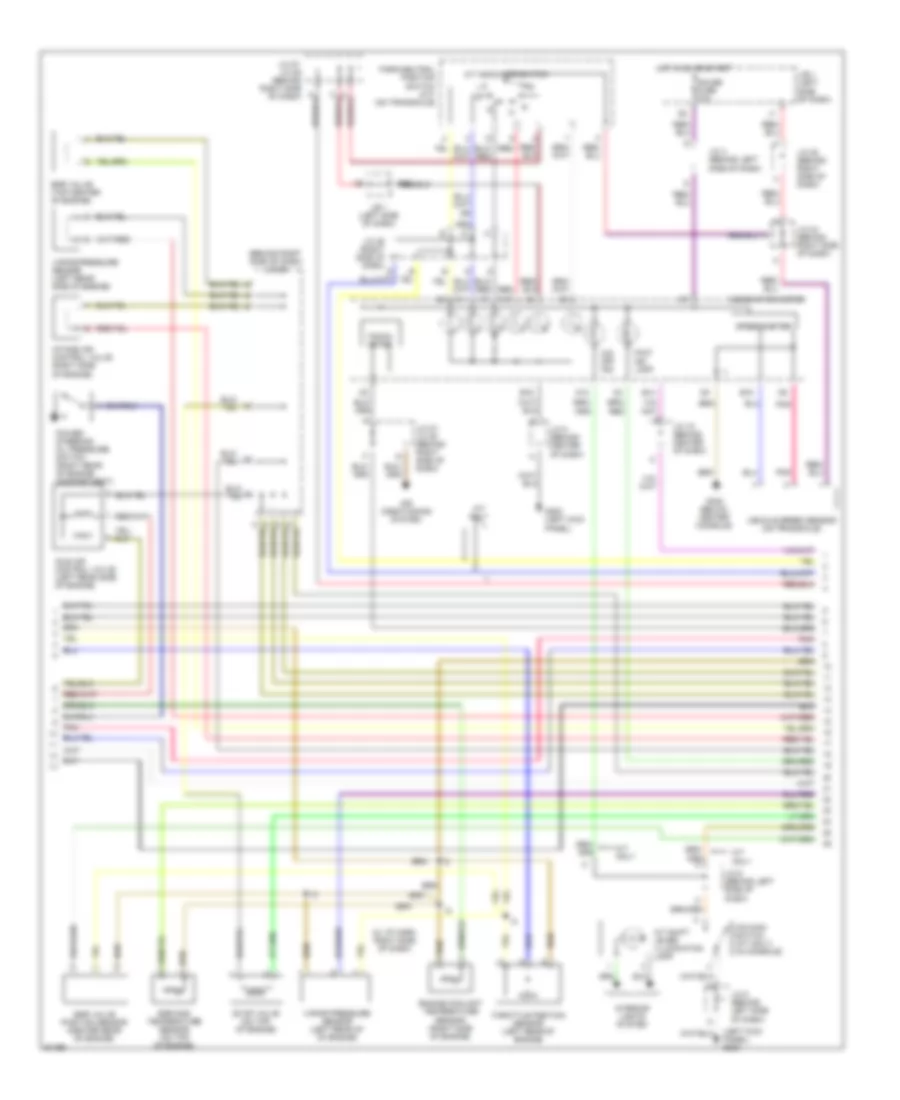
3.0L, Engine Performance Wiring Diagrams (1 of 3) for Toyota Camry CE 1997
 https://portal-diagnostov.com/license.html
Automotive Electricians Portal FZCO
Automotive Electricians Portal FZCO
https://portal-diagnostov.com/license.html
https://portal-diagnostov.com/license.html
Automotive Electricians Portal FZCO
Automotive Electricians Portal FZCOList of elements for 3.0L, Engine Performance Wiring Diagrams (1 of 3) for Toyota Camry CE 1997:
- #10
- #20
- #30
- #40
- #50
- #60
- (a/t only)
- (a/t)
- (i/p harn, right side of dash)
- (rear of engine) g115
- (right side of surge tank)
- (under left quarter pillar)
- Acc
- Adj1
- Am2
- C10
- Camshaft position sensor (lower left front of engine)
- Circuit opening relay
- Conn e10
- Conn e9
- Crankshaft position sensor (lower right front of engine)
- Cruise control system (a/t)
- E01
- E02
- E03
- Efi fuse 15a
- Efi relay
- Electronic controlled transmission solenoid (on transmission)
- Engine control module (behind right side of dash)
- Fuel pump (on top of fuel tank)
- G106 (behind left headlamp)
- G117
- G131 (on intake manifold)
- G22+
- G904
- Gnd
- Hot at all times
- Igc1
- Igc2
- Igc3
- Igf
- Ign fuse 5a
- Igniter (left side of engine compartment)
- Ignition coil no.1
- Ignition coil no.2
- Ignition coil no.3
- Ignition switch
- Igt1
- Igt2
- Igt3
- Injector no. 1
- Injector no. 2
- Injector no. 3
- Injector no. 4
- Injector no. 5
- Injector no. 6
- J/b 1 (left kick panel)
- J/b 2 (left side of engine compartment)
- J/c 18 (behind right side of dash)
- J/c 22 (behind right side of dash)
- J/c 26 (behind right side of dash)
- J/c 29 (behind right side of dash)
- J/c 40
- Knkl
- Knkr
- Knock sensor 1 (top front of engine)
- Knock sensor 2 (top front of engine)
- Lock
- Nc2+
- Nc2-
- Ne+
- Ne-
- Noise filter (left side of engine compt)
- Nsw
- On ig2
- On st2
- Oxl1
- Oxr1
- Pnk
- R/b 1 (left side of engine compartment)
- Red
- Rsc
- Rso
- Sln+
- Sln-
- Sta
- Start
- Starter fuse 5a
- Starting/ charging system
- Tha
- Thw
- Vehicle speed sensor (a/t only) (on transaxle housing)
- Vta1
3.0L, Engine Performance Wiring Diagrams (2 of 3) for Toyota Camry CE 1997
 https://portal-diagnostov.com/license.html
Automotive Electricians Portal FZCO
Automotive Electricians Portal FZCO
https://portal-diagnostov.com/license.html
https://portal-diagnostov.com/license.html
Automotive Electricians Portal FZCO
Automotive Electricians Portal FZCOList of elements for 3.0L, Engine Performance Wiring Diagrams (2 of 3) for Toyota Camry CE 1997:
- (behind right side of dash) j/c 20
- (i2: i/p harn, right side of dash)
- (left kick panel) g200
- A/t indicator switch
- A/t only
- A/t shift lever illumination lamp
- A10
- A11
- A12
- Air conditioning system
- B14
- B15
- B16
- Combination meter
- Egr gas temperature sensor (on top of engine)
- Egr valve (top center of engine)
- Egr valve position sensor (center rear of engine)
- Engine coolant temperature sensor (right side of engine)
- Evap valve (on top of engine)
- G200 (left kick panel)
- G302 (below center console)
- Gauge fuse 10a
- H10
- Hot in on or start
- Idle air control valve (left rear side of engine)
- Intake air control valve (right side of engine)
- Interior lights system
- J/b 1 (left side of dash)
- J/c 15 (behind center of dash)
- J/c 24 (behind right side of dash)
- J/c 27, j/c 28 (behind right side of dash)
- J/c 28 (behind right side of dash)
- J/c 29 (right side of dash)
- J/c 4 (behind left side of dash)
- J/c 5 (behind center of dash)
- J/c 5 (behind left side of dash)
- J/c 6 (behind left side of dash)
- Malf ind lamp
- O/d main switch (a/t only) (in console)
- O/d off ind
- Park/neutral position switch (a/t) (on transaxle)
- Pnk
- Power steering oil pressure switch (right rear of engine compartment)
- Red
- Speedometer
- Tacho- meter
- Throttle position sensor (left rear of engine)
- Vapor pressure sensor (left rear side of engine)
- Vapor pressure sensor (left rear of of engine)
- Vehicle speed sensor (on transaxle)
3.0L, Engine Performance Wiring Diagrams (3 of 3) for Toyota Camry CE 1997
 https://portal-diagnostov.com/license.html
Automotive Electricians Portal FZCO
Automotive Electricians Portal FZCO
https://portal-diagnostov.com/license.html
https://portal-diagnostov.com/license.html
Automotive Electricians Portal FZCO
Automotive Electricians Portal FZCOList of elements for 3.0L, Engine Performance Wiring Diagrams (3 of 3) for Toyota Camry CE 1997:
- (a/t)
- (i/p harn, behind right side of dash)
- A/c
- A/c system
- Acis
- Act
- Anti-lock brakes system
- Bat
- Batt
- Conn e7
- Conn e8
- Cooling fans system
- Cruise control system
- Data link connector 1 (check connector) (right rear side of engine compartment)
- Data link connector 3 (behind left side of dash)
- E2g
- Egls
- Egr
- Els
- Els2
- Engine control module (behind right side of dash)
- Evp1
- G117 (rear side of surge tank)
- G206 (center of i/p)
- Heated oxygen sensor (bank 1 sensor 1) (center rear of engine)
- Heated oxygen sensor (bank 1 sensor 2) (under center of vehicle)
- Heated oxygen sensor (bank 2 sensor 1) (top right side of engine)
- Hot at all times
- Hot at all times
- Hot with rear defogger on
- Htl
- Htr
- Htr2
- Hts
- I2 (i/p harn, behind right side of dash)
- J/b 1 (left side of dash)
- J/b 1 (left kick panel)
- J/b 1 (left side of dash)
- J/c
- J/c 12 (behind top center of dash)
- J/c 22 (behind right side of dash)
- J/c 27, j/c 28 (behind right side of dash)
- J/c 27, j/c 28 (right side of dash)
- J/c 7, j/c 8 (behind left side of dash)
- J10
- J11
- Mass air flow meter (left rear corner 0f engine compt)
- Mirror- heater fuse 10a
- Neo
- Obd trac fuse 7.5a
- Od1
- Od2
- Odlo
- Oxs
- Pnk
- Ptnk
- Sil
- Spd
- Stop fuse 15a
- Stop light switch (behind left side of dash)
- Stp
- Tach
- Tail fuse 10a
- Te1
- Tha
- Thg
- Tpc

 Čeština
 Dansk
Dansk Deutsch
 Ελληνικά
 English
 English
 Español
 Suomi
Suomi Français
 Français
 עברית
עברית Hrvatski
 Magyar
 Italiano
 日本語
日本語 Nederlands
 Polski
 Português
 Português
 Română
 Русский
 Slovenčina
 Slovenščina
 Svenska
 Türkçe
 中文 (中国)
