ENGINE PERFORMANCE
4.7L
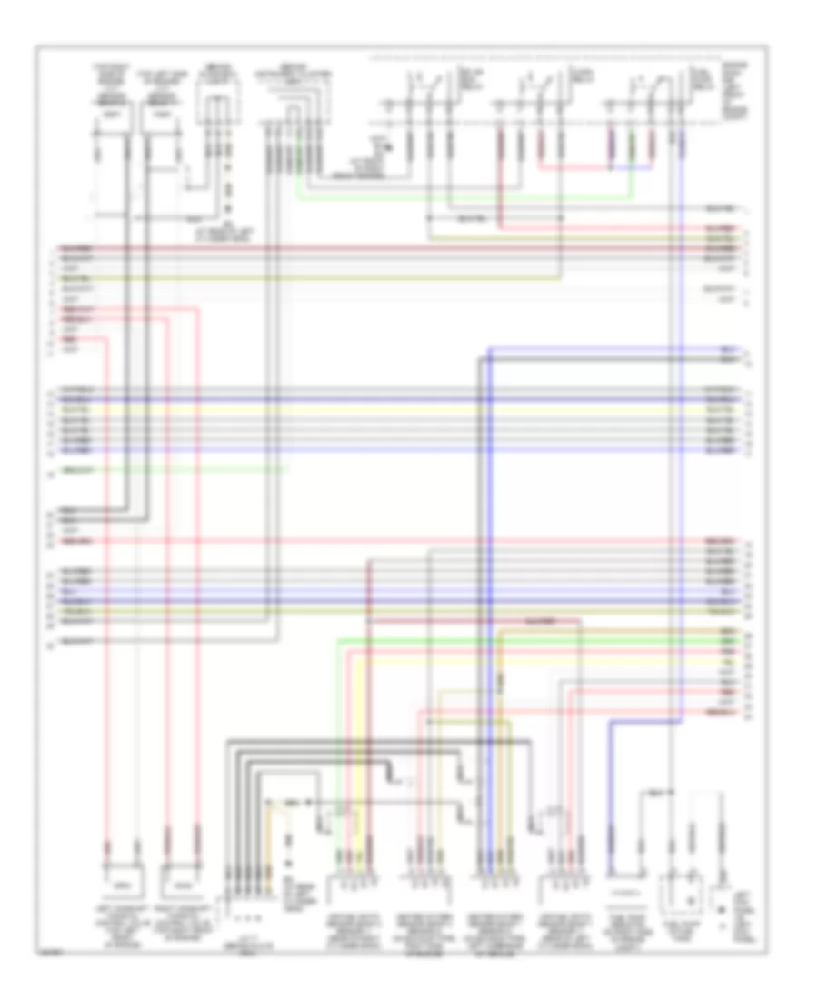
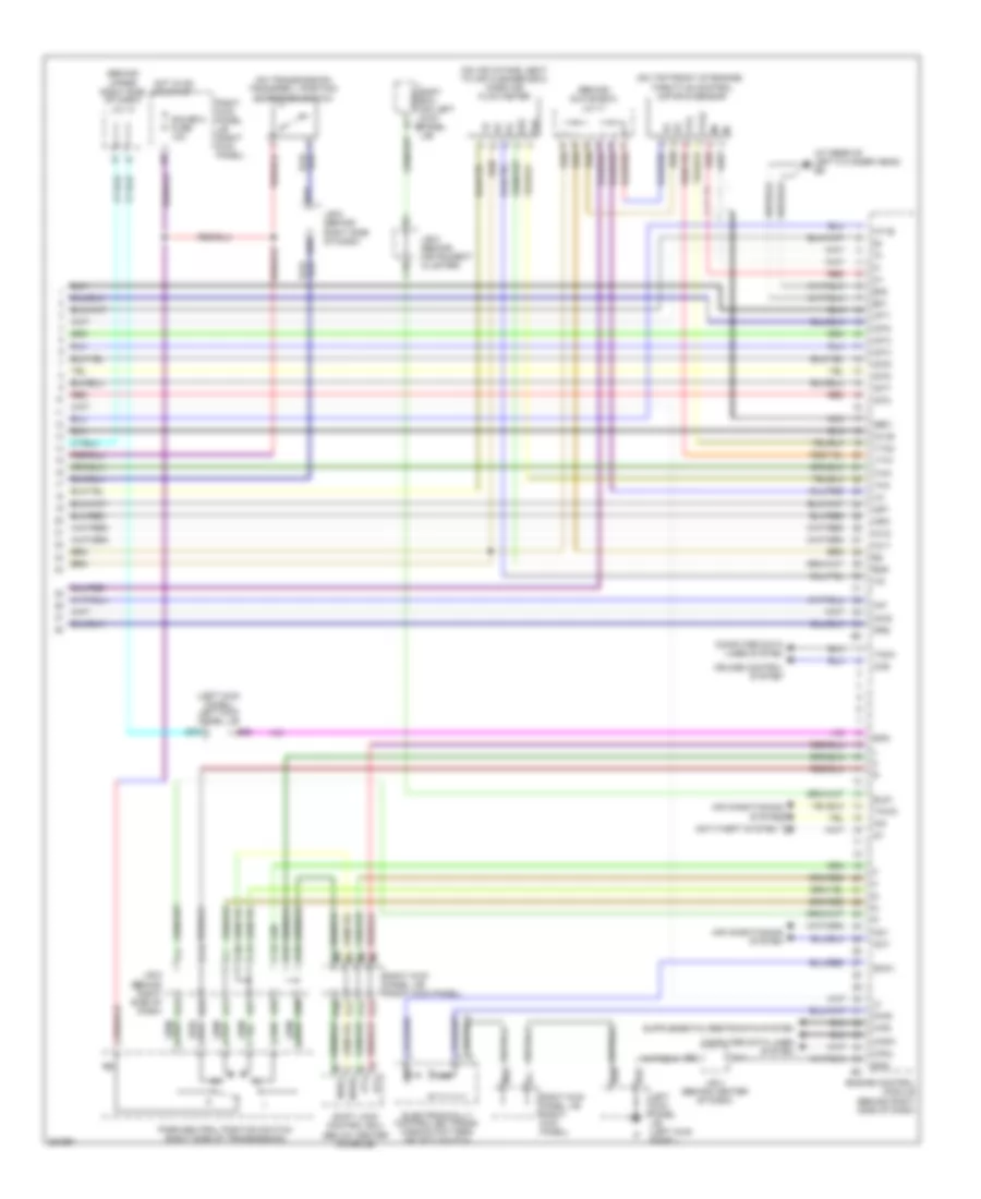
4.7L, Engine Performance Wiring Diagram (1 of 6) for Toyota Land Cruiser 2007
 https://portal-diagnostov.com/license.html
Automotive Electricians Portal FZCO
Automotive Electricians Portal FZCO
https://portal-diagnostov.com/license.html
https://portal-diagnostov.com/license.html
Automotive Electricians Portal FZCO
Automotive Electricians Portal FZCO
List of elements for 4.7L, Engine Performance Wiring Diagram (1 of 6) for Toyota Land Cruiser 2007:
- (at rear of left cylinder head) ed
- (on left front of engine) crankshaft position sensor
- (on top left side of engine) camshaft position sensor
- (right kick panel) right kick panel j/b
- (top left of engine) injectors
- (top right of engine) injectors
- +b2
- A52
- A53
- Accel position sensor (near accelerator pedal assembly)
- Accr
- Aidi
- Air injection control driver (left side of engine compartment)
- Air pump (top center of engine)
- Air switching valve (top center of engine)
- Airp
- Airv
- B10
- Batt
- Bm+
- Computer data lines system
- D10
- D11
- D12
- D31
- D34
- D35
- D36
- E26
- Ee (at left front fender apron)
- Efi or ecd 2 fuse 10a
- En (top center of engine)
- Engine control module (behind right side of dash)
- Ep1
- Ep2
- Epa
- Epa2
- Fpr
- G2+
- G2-
- Hot at all times
- Igsw
- J/b 5 (behind instrument cluster)
- J/b 6 (behind right side of dash)
- J/c 17 (behind glove box)
- K16
- Left kick panel j/b (left kick panel)
- Mpmp
- Mrel
- Nca
- Ne+
- Ne-
- Oc1+
- Oc1-
- Oc2+
- Oc2-
- Ppmp
- Q45
- Red
- Sip
- Siv
- Sta
- Starting/charging system
- Stop fuse 15a
- Stop light switch (on bracket, above brake pedal)
- Stp
- Stsw
- Vcp1
- Vcp2
- Vcpa
- Vpa
- Vpa1
- Vpa2
- Vpmp
- Vv1+
- Vv1-
- Vv2+
- Vv2-
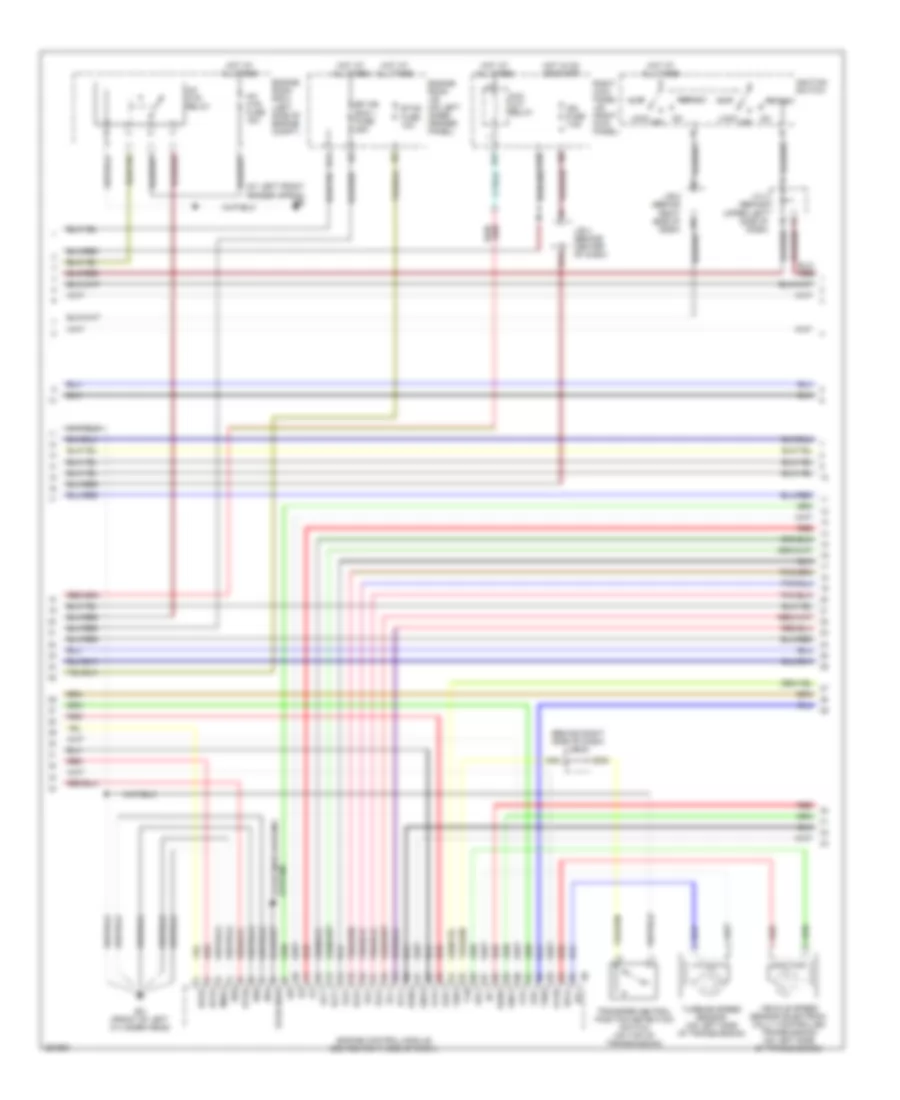
4.7L, Engine Performance Wiring Diagram (2 of 6) for Toyota Land Cruiser 2007
 https://portal-diagnostov.com/license.html
Automotive Electricians Portal FZCO
Automotive Electricians Portal FZCO
https://portal-diagnostov.com/license.html
https://portal-diagnostov.com/license.html
Automotive Electricians Portal FZCO
Automotive Electricians Portal FZCOList of elements for 4.7L, Engine Performance Wiring Diagram (2 of 6) for Toyota Land Cruiser 2007:
- (at rear of left cylinder head)
- (behind glove box) j/c 17
- (behind instrument cluster) j/b 5
- (top left side of engine) vvt sensor (bank 1)
- (top right side of engine) vvt sensor (bank 2)
- Af+
- Af-
- Air fuel ratio sensor (bank 1 sensor 1) (rear of left cylinder bank)
- Air fuel ratio sensor (bank 2 sensor 1) (rear of right cylinder bank)
- C/opn relay
- D13
- D15
- D16
- Ea (at front of right front fender)
- Ed (at rear of left cylinder head)
- Efi or ecd relay
- Engine room r/b (left front of engine compt)
- Fuel pump (in fuel tank)
- Fuel pump relay
- Fuel pump resistor (on right side of engine compt)
- Heated oxygen sensor (bank 1 sensor 2) (on exhaust pipe, left underside of vehicle)
- Heated oxygen sensor (bank 2 sensor 2) (on exhaust pipe, right side of engine)
- J/c 17 (behind glove box)
- K23
- Left camshaft timing oil control valve (top left front of engine)
- Left kick panel j/b (left kick panel)
- Nca
- Red
- Right camshaft timing oil control valve (top right front of engine)
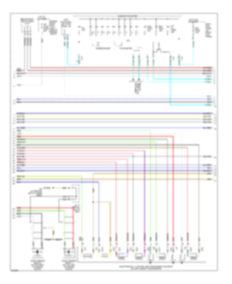
4.7L, Engine Performance Wiring Diagram (3 of 6) for Toyota Land Cruiser 2007
 https://portal-diagnostov.com/license.html
Automotive Electricians Portal FZCO
Automotive Electricians Portal FZCO
https://portal-diagnostov.com/license.html
https://portal-diagnostov.com/license.html
Automotive Electricians Portal FZCO
Automotive Electricians Portal FZCOList of elements for 4.7L, Engine Performance Wiring Diagram (3 of 6) for Toyota Land Cruiser 2007:
- (at left front fender apron) ee
- (behind right side of dash) j/b 6
- A/f htr fuse 15a
- A/f htr relay
- A1a+
- A1a-
- A2a+
- A2a-
- Acc
- Acc cut relay
- B11
- B22
- D38
- D39
- E03
- E04
- E05
- E14
- Efi or ecd 1 fuse 25a
- Ekn2
- Eknk
- Engine control module (behind right side of dash)
- Engine room j/b (on left inner fender panel)
- Engine room r/b 8 (left side of engine compt)
- Eo (front of left cylinder head)
- Etcs fuse 10a
- Ha1a
- Ha2a
- Hot at all times
- Hot in on or start
- Ht2b
- Ign fuse 7.5a
- Ignition switch
- J/b 4 (behind center of dash)
- J/b 6 (behind right side of dash)
- J/c 4 (behind upper left side of dash)
- Knk1
- Knk2
- Lock
- Me01
- Nt+
- Nt-
- Off
- Ox2b
- Q51
- Red
- Right kick panel j/b (right kick panel)
- Sl1+
- Sl1-
- Sl2+
- Sl2-
- Slt+
- Slt-
- Slu+
- Slu-
- Sp2+
- Sp2-
- Star nsw
- Start
- Starting/charging system
- Tfn
- Th01
- Th02
- Transfer neutral position detection switch (on top of transmission)
- Turbine speed sensor (on left side of transmission)
- Vehicle speed sensor (electroni- cally controlled transmission) (on left side of transmission)
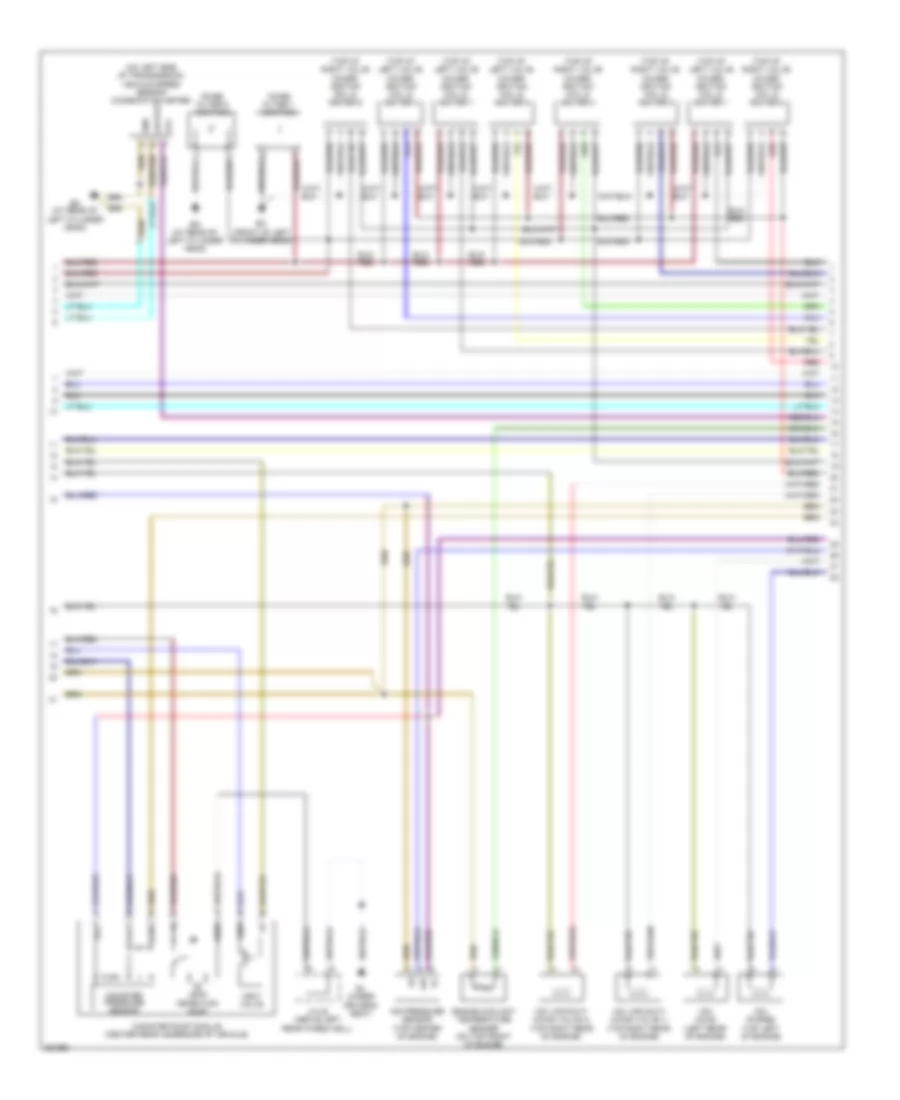
4.7L, Engine Performance Wiring Diagram (4 of 6) for Toyota Land Cruiser 2007
 https://portal-diagnostov.com/license.html
Automotive Electricians Portal FZCO
Automotive Electricians Portal FZCO
https://portal-diagnostov.com/license.html
https://portal-diagnostov.com/license.html
Automotive Electricians Portal FZCO
Automotive Electricians Portal FZCOList of elements for 4.7L, Engine Performance Wiring Diagram (4 of 6) for Toyota Land Cruiser 2007:
- (behind right side of dash) j/c 27
- (left kick panel) left kick panel j/b
- 2nd strt ind
- A/t oil temp ind
- Air pump fuse 50a
- At/ p
- C12
- C13
- C15
- Combination meter
- Cpu
- D32
- Data lines computer
- Ect pwr ind
- Ed (at rear of left cylinder head)
- Electronically controlled transmission solenoid (on left side of transmission)
- Engine room r/b 8 (left side of engine compt)
- Hot at all times
- Hot in on or start
- J/c 17 (behind glove box)
- Knock sensor (bank 1) (on top left of engine block)
- Knock sensor (bank 2) (on top right of engine block)
- Met fuse 7.5a
- Mil ind
- Nca
- Ot+
- Ot-
- Ot2+
- Ot2-
- Q78
- Red
- Right kick panel j/b (right kick panel)
- Sl1+
- Sl1-
- Sl2+
- Sl2-
- Slt+
- Slt-
- Slu+
- Slu-
- Speedometer
- System
- Tachometer
4.7L, Engine Performance Wiring Diagram (5 of 6) for Toyota Land Cruiser 2007
 https://portal-diagnostov.com/license.html
Automotive Electricians Portal FZCO
Automotive Electricians Portal FZCO
https://portal-diagnostov.com/license.html
https://portal-diagnostov.com/license.html
Automotive Electricians Portal FZCO
Automotive Electricians Portal FZCOList of elements for 4.7L, Engine Performance Wiring Diagram (5 of 6) for Toyota Land Cruiser 2007:
- (on left side of transmission) vehicle speed sensor (combination meter)
- (top of left valve cover) ignition coil & igniter 1
- (top of left valve cover) ignition coil & igniter 3
- (top of left valve cover) ignition coil & igniter 5
- (top of left valve cover) ignition coil & igniter 7
- (top of right valve cover) ignition coil & igniter 2
- (top of right valve cover) ignition coil & igniter 4
- (top of right valve cover) ignition coil & igniter 6
- (top of right valve cover) ignition coil & igniter 8
- Aip
- Air pressure sensor (top center of engine)
- Bj (under driver's seat)
- Canister pressure sensor
- Canister pump module (center rear underside of vehicle)
- Ed (at rear of left cylinder head)
- Engine coolant temperature sensor (on top front of engine)
- Eo (front of left cylinder head)
- Gnd
- J/c 22 (above left rear wheelwell)
- Leak detection pump
- Noise filter 1 (ignition)
- Noise filter 5 (ignition)
- Output
- Red
- Sgnd
- Vcc
- Vent valve
- Vout
- Vsv (acis) (left rear of engine)
- Vsv (air swit- ching valve 1) (top right rear of engine)
- Vsv (air swit- ching valve 2) (top right rear of engine)
- Vsv (purge) (top left of engine)
4.7L, Engine Performance Wiring Diagram (6 of 6) for Toyota Land Cruiser 2007
 https://portal-diagnostov.com/license.html
Automotive Electricians Portal FZCO
Automotive Electricians Portal FZCO
https://portal-diagnostov.com/license.html
https://portal-diagnostov.com/license.html
Automotive Electricians Portal FZCO
Automotive Electricians Portal FZCOList of elements for 4.7L, Engine Performance Wiring Diagram (6 of 6) for Toyota Land Cruiser 2007:
- (at rear of left cylinder head) ed
- (behind glove box) j/c 17
- (behind upper right side of dash) j/c 14
- (left kick panel) left kick panel j/b
- (on air intake, next to air cleaner box) mass air flow meter
- (on top front of engine) throttle control motor & sensor
- (on transmission) transfer l position detection switch
- 2nd
- Ac1
- Acis
- Act
- Aip
- Air conditioning system
- Aiv1
- Aiv2
- Anti-theft system
- At4
- Atl
- Body ecu (on left kick b7 panel j/b)
- C10
- C11
- C13
- C16
- C17
- C18
- C19
- C20
- Canh
- Canl
- Ccs
- Computer data lines system
- Cruise control system
- D n
- D13
- D17
- D22
- D27
- D28
- D30
- D31
- D33
- D34
- E01
- E02
- E18
- E28
- E2g
- Electronically controlled trans- mission pattern select switch
- Els1
- Engine control module (behind right side of dash)
- Eom
- F/ps
- Gauge 2 fuse 10a
- Ge01
- Hot in on or start
- Ht1b
- Igf1
- Igf2
- Igt1
- Igt2
- Igt3
- Igt4
- Igt5
- Igt6
- Igt7
- Igt8
- Imi
- Imo
- J/b 4 (behind center of dash)
- J/b 5 (behind instrument cluster)
- J/b 6 (behind right side of dash)
- Left kick panel j/b (left kick panel)
- M10
- Nca
- Nssd
- Nssl
- Ox1b
- P10
- P12
- P13
- P14
- Park/neutral position switch (right side of transmission)
- Prg
- Pwr
- Q70
- Red
- Right kick panel j/b (right kick panel)
- Shift lock control ecu (below center console)
- Snwi
- Spd
- Tach
- Tha
- Thw
- Thwo
- Vta
- Vta1
- Vta2

 Čeština
 Dansk
Dansk Deutsch
 Ελληνικά
 English
 English
 Español
 Suomi
Suomi Français
 Français
 עברית
עברית Hrvatski
 Magyar
 Italiano
 日本語
日本語 Nederlands
 Polski
 Português
 Português
 Română
 Русский
 Slovenčina
 Slovenščina
 Svenska
 Türkçe
 中文 (中国)
