NAVIGATION
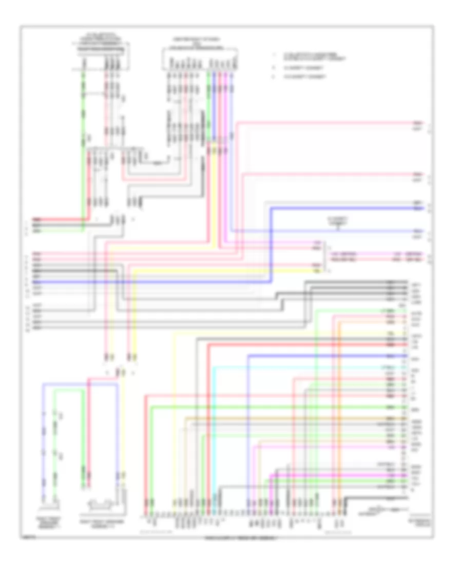
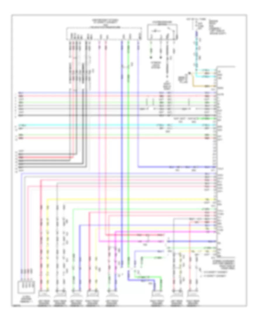
Navigation Wiring Diagram, with Built-in Amplifier (1 of 3) for Toyota 4Runner Trail 2013
 https://portal-diagnostov.com/license.html
Automotive Electricians Portal FZCO
Automotive Electricians Portal FZCO
https://portal-diagnostov.com/license.html
https://portal-diagnostov.com/license.html
Automotive Electricians Portal FZCO
Automotive Electricians Portal FZCO
List of elements for Navigation Wiring Diagram, with Built-in Amplifier (1 of 3) for Toyota 4Runner Trail 2013:
- A50
- A64
- A66
- A87
- A90
- A91
- A95
- Acc fuse 7.5a
- Adpg
- Agnd
- Alo
- Amp fuse 30a
- Antenna
- Aro
- Asgn
- Au1
- Au2
- Auxo
- B17
- B20
- B33
- B35
- B39
- B57
- B59
- Bf2
- C20
- C23
- C31
- Canh
- Canl
- Combination meter assembly
- Computer data lines system
- Driver side j/b assembly (left end of dash)
- Eau
- Ecu-ig 1 fuse 10a
- Ecu-ig 2 fuse 10a
- Engine room r/b assembly (left side of engine compt)
- F23
- Fa2
- Fg1
- G1 (right end of dash)
- G13
- G14
- G31
- Gg1
- Hot at all times
- Hot in on or start
- Hot w/ acc relay energized
- Il+2
- Il-2
- Interior lights system
- J/b 4 (left side of dash)
- J/b 5 (center of dash)
- J/c b48 (right side of dash)
- J/c g13 & g14 (top left g14 side of dash)
- J/c g13 & g14 (top left side of dash)
- Left steering switch
- Macc
- Min+
- Min-
- Mode
- Nca
- Off hook
- On hook
- Park/neutral position switch (right side of transmission)
- Pnk
- Radio & display receiver assembly
- Red
- Rev
- Right steering switch
- Sdars antenna (if equipped)
- Seek+
- Seek-
- Sgnd
- Shield
- Skid control ecu w/ actuator assembly (left rear of engine compt)
- Sns2
- Sp1
- Spd
- Spiral cable sub-assembly (top of steering column)
- Steering pad switch assembly (if equipped)
- Stereo jack adapter assembly 1 (w/o multi-media interface ecu)
- Sw1
- Sw2
- Swg
- Udo+
- Udo-
- Ujsg
- Upo
- Va-
- Val+
- Var+
- Voice
- Volume+
- Volume-
- Woofer speaker switch
- Z11
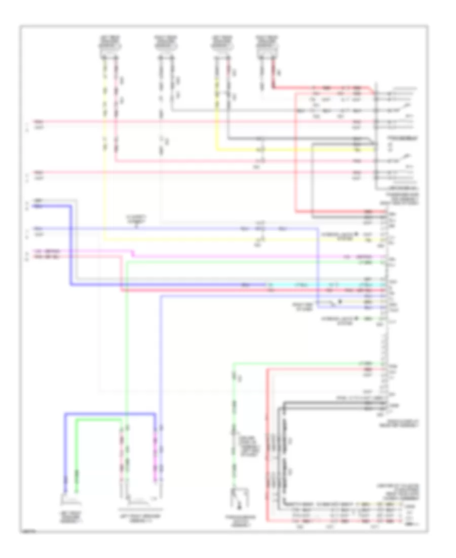
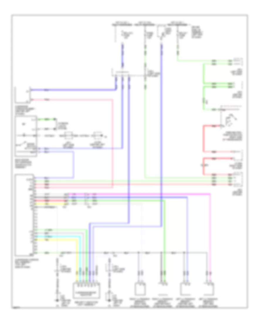
Navigation Wiring Diagram, with Built-in Amplifier (2 of 3) for Toyota 4Runner Trail 2013
 https://portal-diagnostov.com/license.html
Automotive Electricians Portal FZCO
Automotive Electricians Portal FZCO
https://portal-diagnostov.com/license.html
https://portal-diagnostov.com/license.html
Automotive Electricians Portal FZCO
Automotive Electricians Portal FZCOList of elements for Navigation Wiring Diagram, with Built-in Amplifier (2 of 3) for Toyota 4Runner Trail 2013:
- (center right of dash) dcm (telematics transceiver)
- (or pnk)
- Acc
- Agnd
- Avc+
- Avc-
- Extension module
- Fg1
- Fg2
- G34
- Gps antenna
- Gs1
- Hf2
- Hsyn
- Macc
- Mci+
- Mci-
- Mco+
- Mco-
- Mcvd
- Mic+
- Mic-
- Mute
- Nca
- Pnk
- Radio & display receiver assembly
- Red
- Right front speaker assembly 1
- Right front speaker assembly 2
- Sgnd
- Shd1
- Shd2
- Shd3
- Sns2
- Spd
- Spi+
- Spi-
- Spo+
- Spo-
- Su1
- Telephone microphone
- Udo+
- Udo-
- Ujsg
- Usv1
- V-b
- V-g
- V-r
- Vol+
- Vol-
- Vshd
- Vsyn
- W/ safety connect
- W/o safety connect
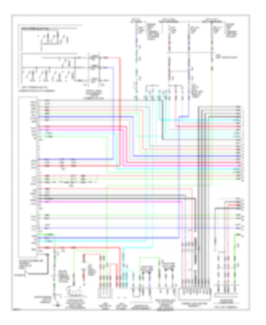
Navigation Wiring Diagram, with Built-in Amplifier (3 of 3) for Toyota 4Runner Trail 2013
 https://portal-diagnostov.com/license.html
Automotive Electricians Portal FZCO
Automotive Electricians Portal FZCO
https://portal-diagnostov.com/license.html
https://portal-diagnostov.com/license.html
Automotive Electricians Portal FZCO
Automotive Electricians Portal FZCOList of elements for Navigation Wiring Diagram, with Built-in Amplifier (3 of 3) for Toyota 4Runner Trail 2013:
- (center of tailgate) (if equipped) rear television camera assembly
- (or pnk)
- (pins: 12 to 14 not used)
- (right end of dash)
- Acc
- B24
- Ca+
- Cb+
- Cgnd
- Cv+
- Cv-
- D17
- Driver side j/b assembly (left end of dash)
- Fa1
- Fg1
- Fl+
- Fl-
- Fn1
- Fo2
- Fr+
- Fr-
- G30
- G32
- G33
- Gnd
- If2
- Ill+
- Ill-
- Interior lights system
- Jn1
- Ko1
- Left eq relay
- Left front speaker assembly 1
- Left front speaker assembly 2
- Left rear speaker assembly 1
- Left rear speaker assembly 2
- Nca
- Parking brake switch assembly
- Passenger side r/b assembly (right end of dash)
- Pkb
- Pnk
- Radio & display receiver assembly
- Red
- Right eq relay
- Right rear speaker assembly 1
- Right rear speaker assembly 2
- Rl+
- Rl-
- Rr+
- Rr-
- Tmut
- Vo1
- Vo2
- Vw1
- W/ safety connect
- Wy1
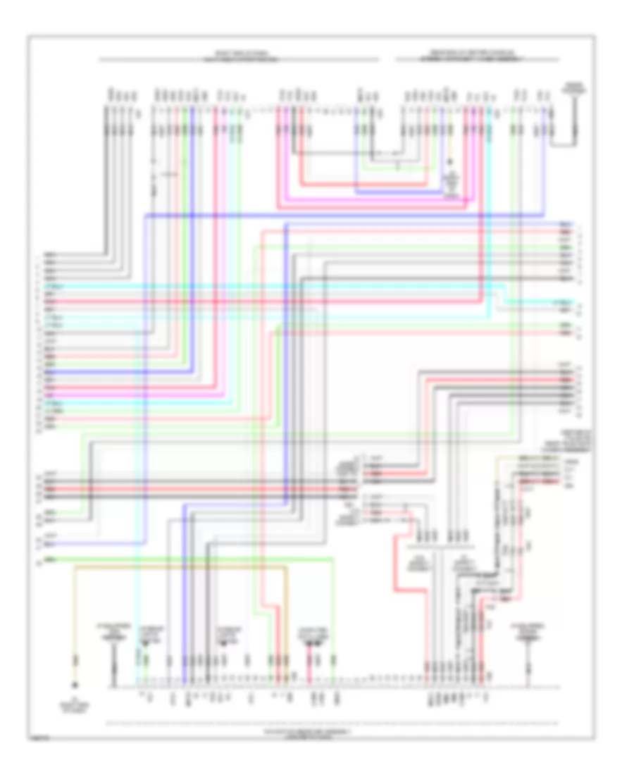
Navigation Wiring Diagram, with Separate Amplifier (1 of 3) for Toyota 4Runner Trail 2013
 https://portal-diagnostov.com/license.html
Automotive Electricians Portal FZCO
Automotive Electricians Portal FZCO
https://portal-diagnostov.com/license.html
https://portal-diagnostov.com/license.html
Automotive Electricians Portal FZCO
Automotive Electricians Portal FZCOList of elements for Navigation Wiring Diagram, with Separate Amplifier (1 of 3) for Toyota 4Runner Trail 2013:
- A50
- A64
- A66
- A87
- A90
- A91
- A95
- Acc
- Acc fuse 7.5a
- Agnd
- Ali
- Alo
- Antenna
- Ari
- Aro
- Asgn
- Au1
- Au2
- Auxi
- Auxo
- B17
- B20
- B24
- B33
- B35
- B39
- B57
- B59
- Bf2
- C20
- C23
- C31
- Canh
- Canl
- Cdl+
- Cdl-
- Cdr+
- Cdr-
- Combination meter assembly
- Computer data lines system
- Csld
- D17
- Driver side j/b assembly (left end of dash)
- Eau
- Ecu ig 1 fuse 10a
- Ecu ig 2 fuse 10a
- Engine room r/b assembly (left side of engine compt)
- F23
- Fa1
- Fa2
- Fg1
- G13
- G14
- G16
- G17
- G18
- G19
- Gg1
- Gn2
- Gnd
- Gs1
- Hot at all times
- Hot w/ acc relay energized
- Hot w/ ig1 1 relay energized
- Ivo+
- Ivo-
- J/b 4 (left side of dash)
- J/b 5 (center of dash)
- J/c b48 (right side of dash)
- J/c g13 & g14 (top left g13
- Left steering switch
- Macc
- Map light assembly
- Mco+
- Mco-
- Mode
- Mute
- Navigation receiver assembly (center of dash)
- Nca
- Off hook
- On hook
- Park/neutral position switch (right side of transmission)
- Parking brake switch assembly
- Pkb
- Pnk
- Rad 1 fuse 10a
- Red
- Rev
- Right steering switch
- Seek+
- Seek-
- Shield
- Side of dash)
- Skid control ecu w/ actuator assembly (left rear of engine compt)
- Sld1
- Sns2
- Sp1
- Spd
- Spiral cable sub-assembly (top of steering column)
- Steering pad switch assembly
- Stereo jack adapter assembly 1
- Su1
- Sw1
- Sw2
- Swg
- Telephone microphone
- Tx1+
- Tx1-
- Txm+
- Txm-
- Txo+
- Txo-
- Udo+
- Udo-
- Ujsb
- Up1
- Voice
- Volume+
- Volume-
- Z11
Navigation Wiring Diagram, with Separate Amplifier (2 of 3) for Toyota 4Runner Trail 2013
 https://portal-diagnostov.com/license.html
Automotive Electricians Portal FZCO
Automotive Electricians Portal FZCO
https://portal-diagnostov.com/license.html
https://portal-diagnostov.com/license.html
Automotive Electricians Portal FZCO
Automotive Electricians Portal FZCOList of elements for Navigation Wiring Diagram, with Separate Amplifier (2 of 3) for Toyota 4Runner Trail 2013:
- (center of tailgate) rear television camera assembly
- (if equipped) gps antenna
- (if equipped) sdars antenna
- (rear end of center console) stereo component tuner assembly
- (right end of dash) multi-media interface ecu
- Acc
- Atx+
- Atx-
- Ca+
- Canh
- Canl
- Cb+
- Cgnd
- Computer data lines system
- Cv+
- Cv-
- Fg1
- Flo+
- Flo-
- Fo2
- Fro+
- Fro-
- G1 (right end of dash)
- G11
- G20
- G23
- G24
- G25
- G27
- G28
- Gnd
- Gs1
- Ill+
- Ill-
- Interior lights system
- Macc
- Min+
- Min-
- Mut1
- Mut2
- Mute
- Navigation receiver assembly (center of dash)
- Nca
- Pnk
- Red
- Sdars antenna
- Sgnd
- Sld
- Sns2
- Tx+
- Tx-
- Tx1+
- Tx1-
- Tx2+
- Tx2-
- Txo+
- Txo-
- Udi+
- Udi-
- Uesg
- Uli+
- Uli-
- Ulo+
- Ulo-
- Upo
- Uri+
- Uri-
- Uro+
- Uro-
- Usd1
- Usd2
- Vo2
- Vw1
- W/ safety connect
- W/o safety connect
- Wy1
Navigation Wiring Diagram, with Separate Amplifier (3 of 3) for Toyota 4Runner Trail 2013
 https://portal-diagnostov.com/license.html
Automotive Electricians Portal FZCO
Automotive Electricians Portal FZCO
https://portal-diagnostov.com/license.html
https://portal-diagnostov.com/license.html
Automotive Electricians Portal FZCO
Automotive Electricians Portal FZCOList of elements for Navigation Wiring Diagram, with Separate Amplifier (3 of 3) for Toyota 4Runner Trail 2013:
- (center right of dash) (w/ safety connect) dcm (telematics transceiver)
- +b2
- Acc
- Amp fuse 30a
- Engine room r/b assembly (left side of engine compt)
- Fa1
- Fg1
- Fg2
- Fl+
- Fl-
- Fo2
- Fr+
- Fr-
- G1 (right end of dash)
- Gn1
- Gn2
- Gnd
- Gnd2
- Hf2
- Hot at all times
- If2
- Il+2
- Il-2
- Int+
- Int-
- Interior lights system
- Jn1
- Ko1
- Left front speaker assembly 1
- Left front speaker assembly 2
- Left rear speaker assembly 1
- Left rear speaker assembly 2
- Mci+
- Mci-
- Mco+
- Mco-
- Mcvd
- Mute
- N11
- N12
- N13
- N14
- N2 (base of right "d" pillar)
- Nca
- Pnk
- R-l+
- R-l-
- R-r+
- R-r-
- Red
- Right front speaker assembly 1
- Right front speaker assembly 2
- Right rear speaker assembly 1
- Right rear speaker assembly 2
- Rl+
- Rl-
- Rr+
- Rr-
- Sgnd
- Sld
- Spd
- Spi+
- Spi-
- Spo+
- Spo-
- Stereo component amplifier assembly (right side of cargo area)
- Sw+
- Sw-
- Tmut
- Twl+
- Twl-
- Twr+
- Twr-
- Tx+
- Tx-
- Vo1
- Vw1
- W/ box speaker assembly 1
- W/ safety connect
- W/o safety connect
- Wf1+
- Wf1-
- Wf2+
- Wf2-
- Woofer speaker switch
Parking Assistant Wiring Diagram for Toyota 4Runner Trail 2013
 https://portal-diagnostov.com/license.html
Automotive Electricians Portal FZCO
Automotive Electricians Portal FZCO
https://portal-diagnostov.com/license.html
https://portal-diagnostov.com/license.html
Automotive Electricians Portal FZCO
Automotive Electricians Portal FZCOList of elements for Parking Assistant Wiring Diagram for Toyota 4Runner Trail 2013:
- A51
- A64
- A66
- A78
- A80
- A81
- B31
- B34
- B35
- B36
- B39
- B40
- B53
- B54
- B57
- B59
- Back sonar or clearance sonar switch assembly
- Bbz
- Bf2
- C18
- C20
- C31
- Clearance sonar indicator
- Clearance warning buzzer 1 (center left of dash)
- Clearance warning ecu assembly (top left side of dash)
- Clsw
- Driver side j/b assembly (left end of dash)
- Ecu
- Ecu ig 1 fuse 10a
- Ecu ig 2 fuse 10a
- Fo1
- Hot w/ ig1 1 relay energized
- Hot w/ tail relay energized
- Ill+
- Ill-
- Ind
- Interior lights system
- J/b 4 (left side of dash)
- J/b 5 (center of dash)
- J/c b48 (right side of dash)
- J/c f64 (center left of dash)
- L10
- Left ultrasonic sensor 1 (center left of rear bumper)
- Left ultrasonic sensor 2 (left end of rear bumper)
- Main body ecu
- Panel fuse 7.5a
- Park/neutral position switch (right side of transmission)
- Pnk
- Po1
- Red
- Right ultrasonic sensor 1 (center right of rear bumper)
- Right ultrasonic sensor 2 (right end of rear bumper)
- Security indicator light assembly
- Sonar switch
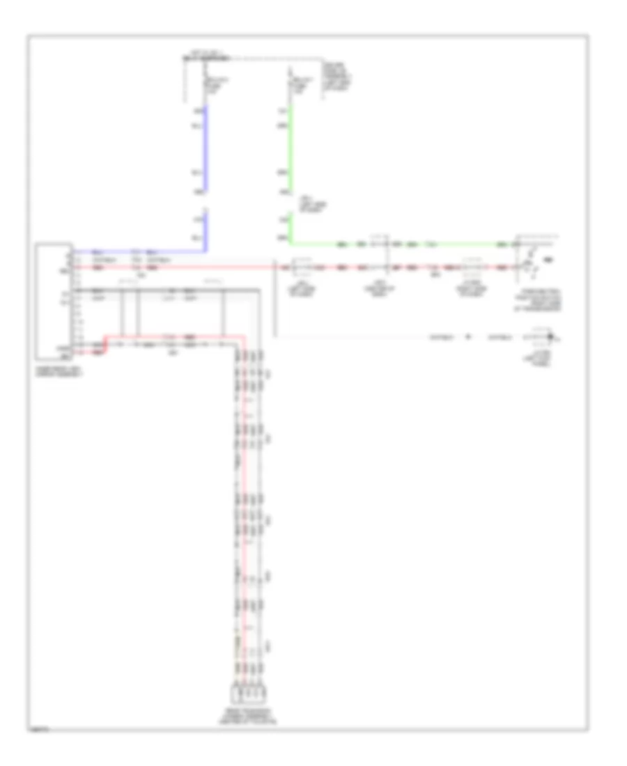
Rear View Camera Wiring Diagram for Toyota 4Runner Trail 2013
 https://portal-diagnostov.com/license.html
Automotive Electricians Portal FZCO
Automotive Electricians Portal FZCO
https://portal-diagnostov.com/license.html
https://portal-diagnostov.com/license.html
Automotive Electricians Portal FZCO
Automotive Electricians Portal FZCOList of elements for Rear View Camera Wiring Diagram for Toyota 4Runner Trail 2013:
- A64
- A66
- A79
- A83
- B33
- B35
- B39
- B57 red
- B59
- Bf2
- C20
- C23
- C31
- Cb+
- Cgkd
- Cgnd
- Cv+
- Cv-
- Driver side j/b assembly (left end of dash)
- Ecu-ig 1 fuse 10a
- Ecu-ig 2 fuse 10a
- Fg1
- Fo2
- Fs1
- Gs1
- Hot w/ ig1 1 relay energized
- Inner rear view mirror assembly
- J/b 4 (left side of dash)
- J/b 5 (center of dash)
- J/c b48 (right side of dash)
- J/c f63 (left kick panel)
- Nca
- Park/neutral position switch (right side of transmission)
- Rear television camera assembly (center of tailgate)
- Red
- Rev
- Vo2
- Vw1
- Wy1
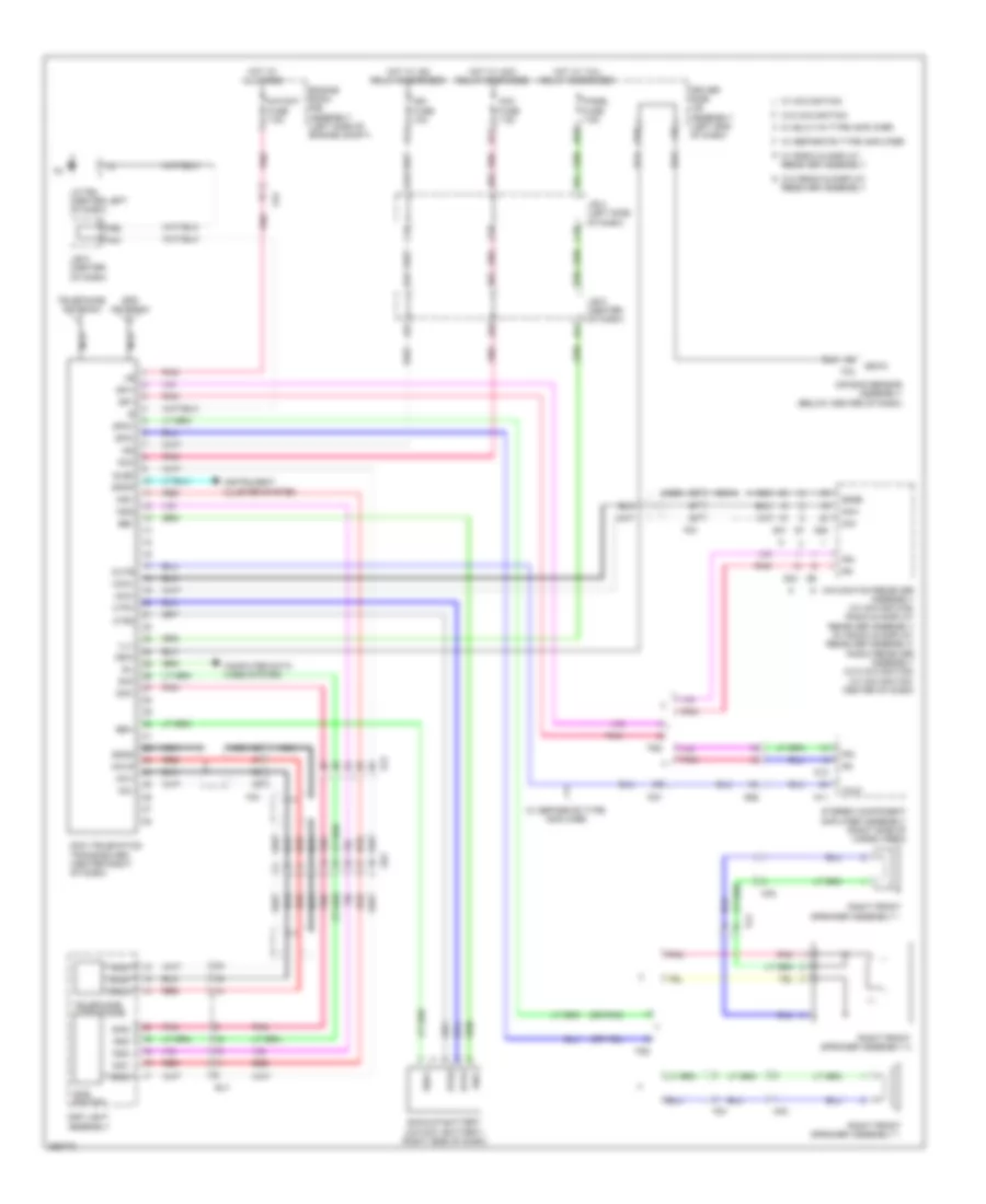
Telematics Wiring Diagram for Toyota 4Runner Trail 2013
 https://portal-diagnostov.com/license.html
Automotive Electricians Portal FZCO
Automotive Electricians Portal FZCO
https://portal-diagnostov.com/license.html
https://portal-diagnostov.com/license.html
Automotive Electricians Portal FZCO
Automotive Electricians Portal FZCOList of elements for Telematics Wiring Diagram for Toyota 4Runner Trail 2013:
- (or pnk)
- A37
- A43
- A44
- A46
- A49
- A50
- A51
- A66
- Acc
- Acc fuse 7.5a
- Air bag sensor assembly (below center of dash)
- B17
- B27
- B36
- B40
- B67
- Backup battery (mayday battery) (right side of dash)
- Bbi+
- Bbi-
- Bbo+
- Bbo-
- Btr1
- Btr2
- C15
- C18
- C50
- C51
- C53
- Computer data lines system
- Ctr1
- Ctr2
- Dcm (telematics transceiver) (center right of dash)
- Driver side j/b assembly (left end of dash)
- Engine room r/b assembly (left side of engine compt)
- F33
- Fa2
- Fg1
- Fg2
- Fr+
- Fr-
- G20
- G31
- G33
- Gn2
- Gnd
- Gps antenna
- Gs1
- Gsw
- Gsw3
- Hf2
- Hot at all times
- Hot w/ acc relay energized
- Hot w/ ig2 relay energized
- Hot w/ tail relay energized
- Ig2
- Ign fuse 10a
- Ill+
- Ind1
- Ind2
- Instrument cluster system
- J/b 4 (left side of dash)
- J/b 5 (center of dash)
- J/c f64 (center left of dash)
- Macc
- Map light assembly
- Mayday fuse 7.5a
- Mci+
- Mci-
- Mco+
- Mco-
- Mcvd
- Min+
- Min-
- Mute
- N11
- N12
- Navigation receiver assembly (w/ navigation) radio & display receiver assembly (w/ radio & display receiver assembly) radio receiver assembly (w/o navigation) (w/ navigation: center of dash)
- Nca
- Panel fuse 7.5a
- Pnk
- Red
- Right front speaker assembly 1
- Right front speaker assembly 2
- Rrid
- Sgnd
- Sig-
- Sig1
- Sig2
- Sil
- Sled
- Sos switch
- Spdp
- Spi+
- Spi-
- Spo+
- Spo-
- Stereo component amplifier assembly (right side of cargo area)
- Su1
- Telephone antenna
- Telephone microphone
- Tmut
- W/ built-in type amplifier
- W/ navigation
- W/ radio & display receiver assembly
- W/ separate type amplifier
- W/o navigation
- W/o radio & display receiver assembly

 Čeština
 Dansk
Dansk Deutsch
 Ελληνικά
 English
 English
 Español
 Suomi
Suomi Français
 Français
 עברית
עברית Hrvatski
 Magyar
 Italiano
 日本語
日本語 Nederlands
 Polski
 Português
 Português
 Română
 Русский
 Slovenčina
 Slovenščina
 Svenska
 Türkçe
 中文 (中国)
