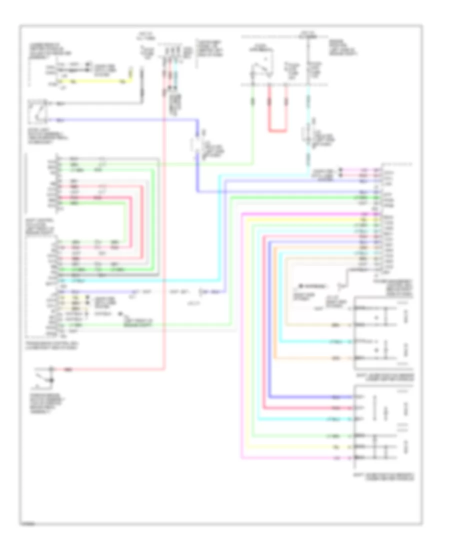
SHIFT INTERLOCK
Shift Interlock Wiring Diagram for Toyota Prius V 2012
 https://portal-diagnostov.com/license.html
Automotive Electricians Portal FZCO
Automotive Electricians Portal FZCO
https://portal-diagnostov.com/license.html
https://portal-diagnostov.com/license.html
Automotive Electricians Portal FZCO
Automotive Electricians Portal FZCO
List of elements for Shift Interlock Wiring Diagram for Toyota Prius V 2012:
- (right side of dash)
- (under rear of center console) navigation receiver assembly
- A16
- A22
- A23
- A24
- A4 (left front of engine compt)
- A52
- A53
- Al1
- Batt
- Bma
- C11
- C20
- Ca1h
- Ca1l
- Canh
- Canl
- Computer data lines system
- Da1
- Da2
- E01
- E2x1
- E2x2
- Engine room r/b (left side of engine compt)
- Eo2
- Hall ic
- Hot at all times
- Instrument panel j/b (behind left end of dash)
- J/c a52 & a53 (left side of dash) a52
- J/c a52 & a53 (left side of dash) a53
- J/c l71
- J/c l87 (right end of dash)
- L37
- L38
- Lin
- Lin2
- Main body ecu
- Mua
- Mva
- Mwa
- P-con main fuse 7.5a
- P-con mtr fuse 30a
- P-con mtr relay
- Parking brake switch assembly (top of parking brake pedal assembly)
- Pcon
- Pkb
- Plb
- Pnk
- Power management control ecu (behind right side of dash)
- Ppos
- Re2
- Red
- Rvc
- Shift control actuator (left front of engine compt)
- Shift lever position sensor (under center console)
- Shift lever position sensor 2 (under center console)
- Stop fuse 10a
- Stop light switch assembly (above brake pedal, on bracket)
- Stp
- Transmission control ecu (lower right end of dash)
- Vcx1
- Vcx2
- Vcx3
- Vcx4
- Vsx1
- Vsx2
- Vsx3
- Vsx4
 Čeština
 Dansk
Dansk Deutsch
 Ελληνικά
 English
 English
 Español
 Suomi
Suomi Français
 Français
 עברית
עברית Hrvatski
 Magyar
 Italiano
 日本語
日本語 Nederlands
 Polski
 Português
 Português
 Română
 Русский
 Slovenčina
 Slovenščina
 Svenska
 Türkçe
 中文 (中国)
 한국어
한국어
