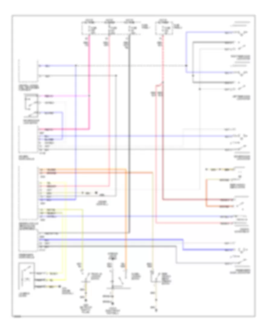
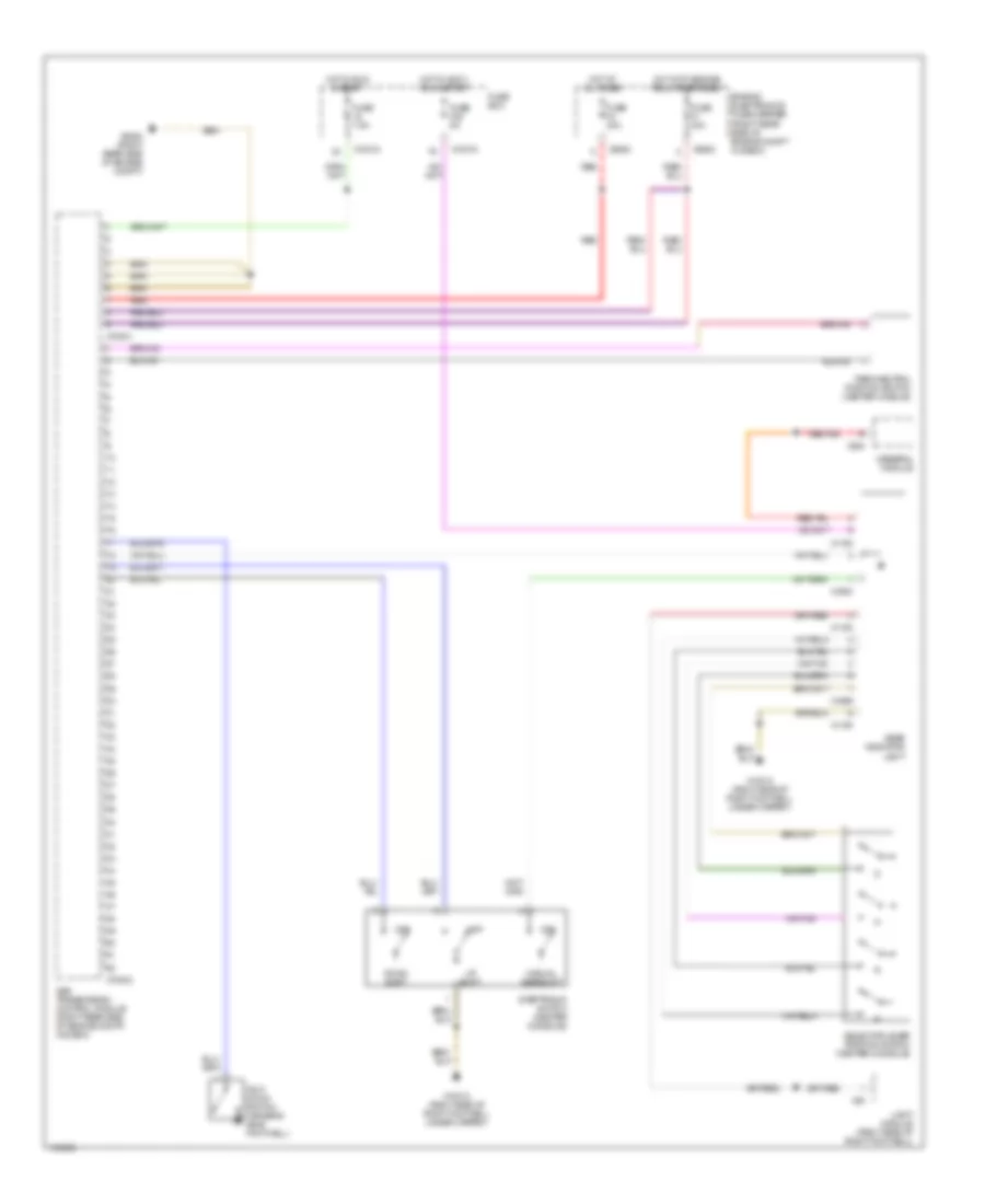
AIR CONDITIONING
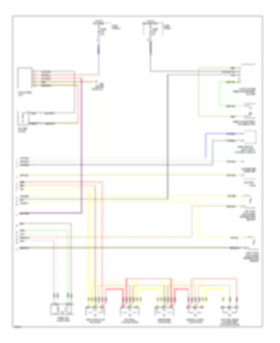
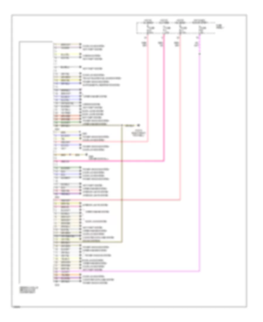
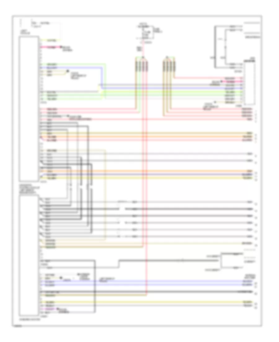
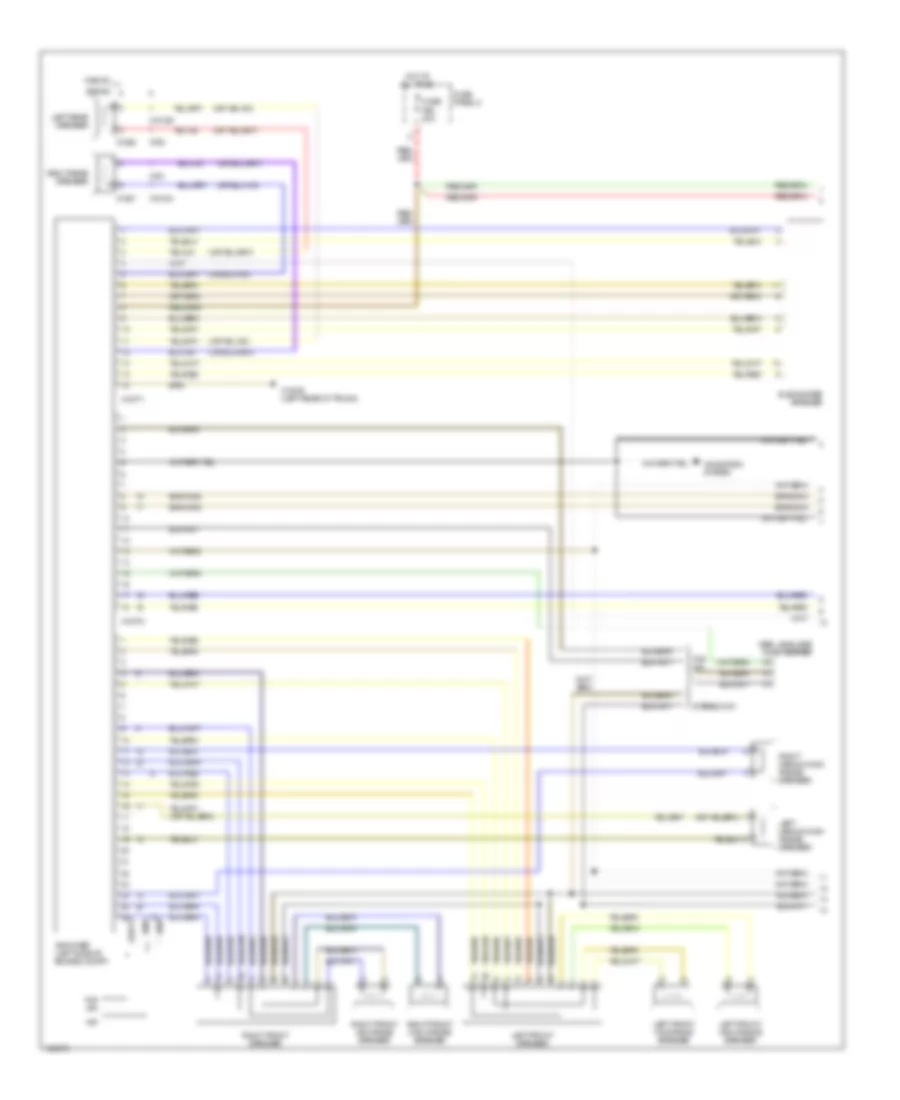
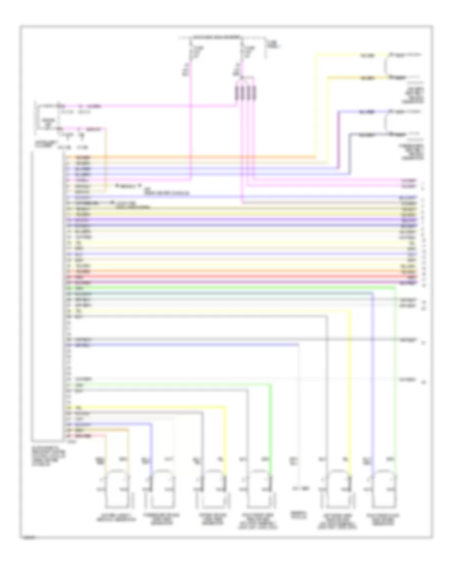
Automatic A/C Wiring Diagram (1 of 2) for BMW 540i 1998
 https://portal-diagnostov.com/license.html
Automotive Electricians Portal FZCO
Automotive Electricians Portal FZCO
https://portal-diagnostov.com/license.html
https://portal-diagnostov.com/license.html
Automotive Electricians Portal FZCO
Automotive Electricians Portal FZCO
List of elements for Automatic A/C Wiring Diagram (1 of 2) for BMW 540i 1998:
- 2.8l
- 4.4l
- A/c compressor
- Automatic air recirculation sensor
- Auxiliary water pump
- Computer data lines system
- Defogger system
- Dual temperature sensor
- Engine control module (right rear of engine compt)
- Evaporator temperature sensor
- Fuse f20 5a
- Fuse f9 15a
- Fuse panel 1
- Heating & a/c control module
- High pressure switch
- Hot at all times
- Hot in run or start
- Interior lights system
- Nca
- Rear compartment blower
- Rear grille
- Red
- Temperature sensor latent heat accumulator
- W/ latent heat accumulator
- Wiper/washer system
- X165 (left front of engine compt)
- X18153
- X18341
- X492 (driver door sill)
- X6000
- X60003
- X60004
- X610
- X611
- X613
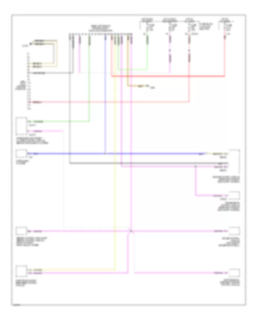
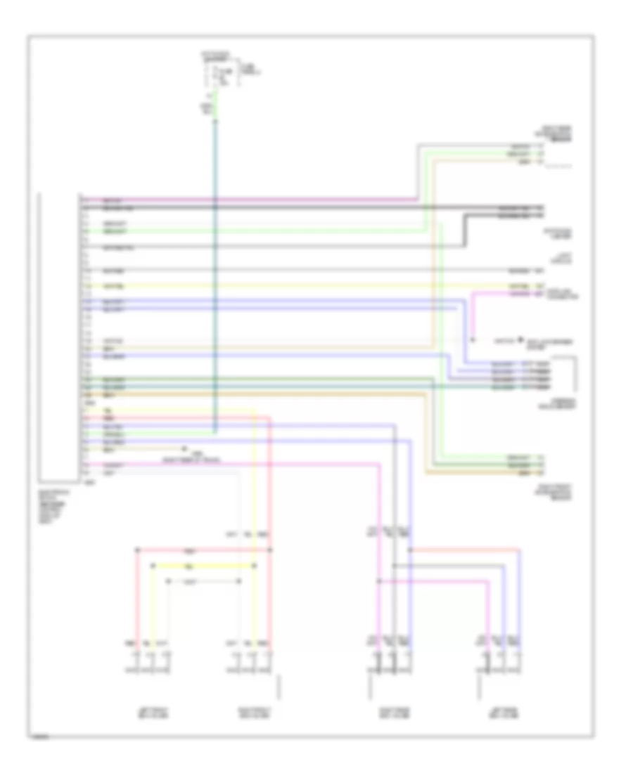
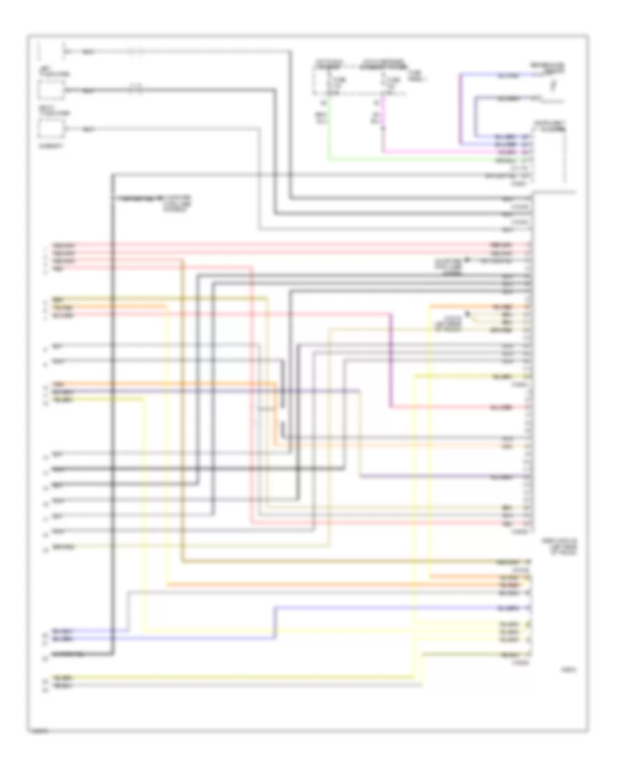
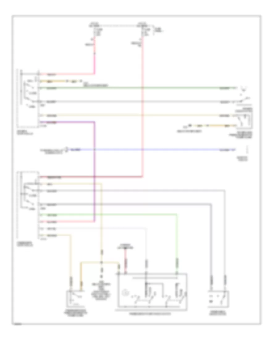
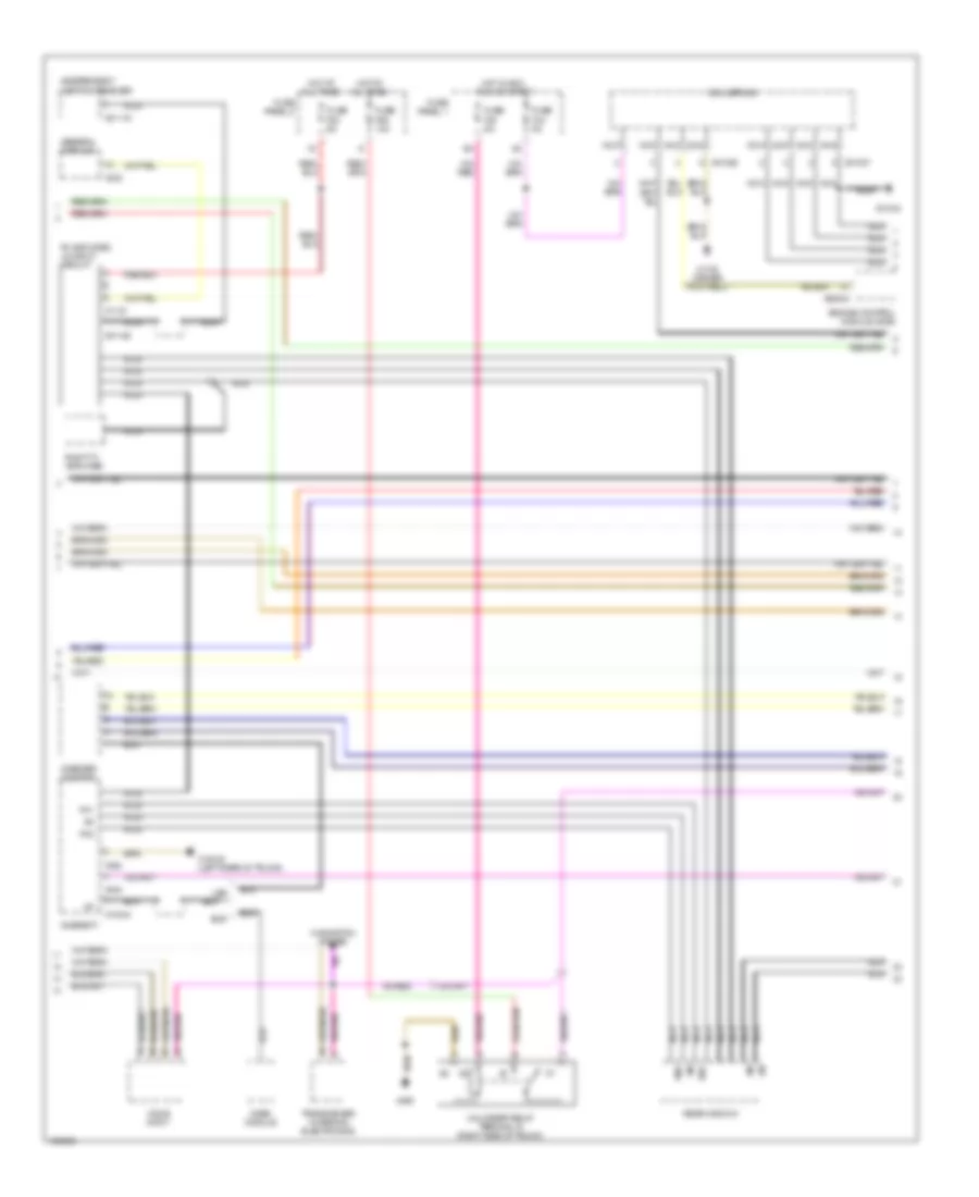
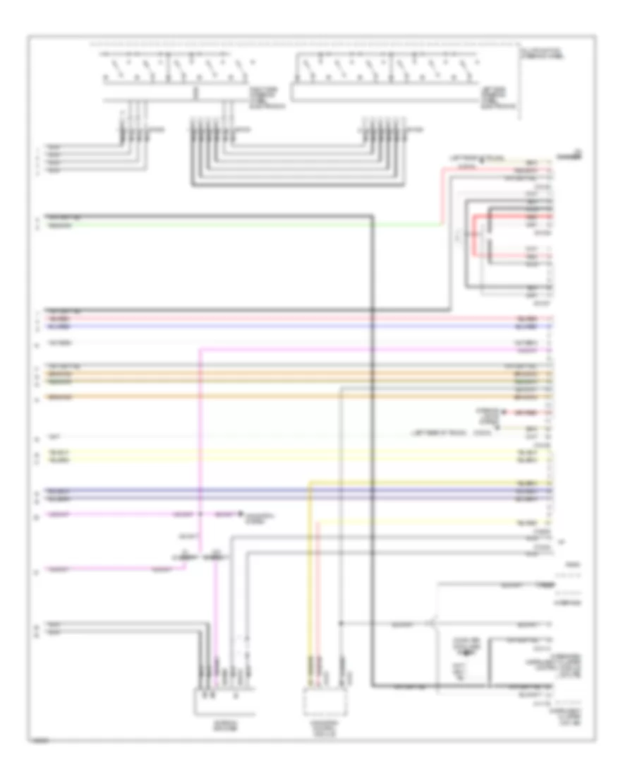
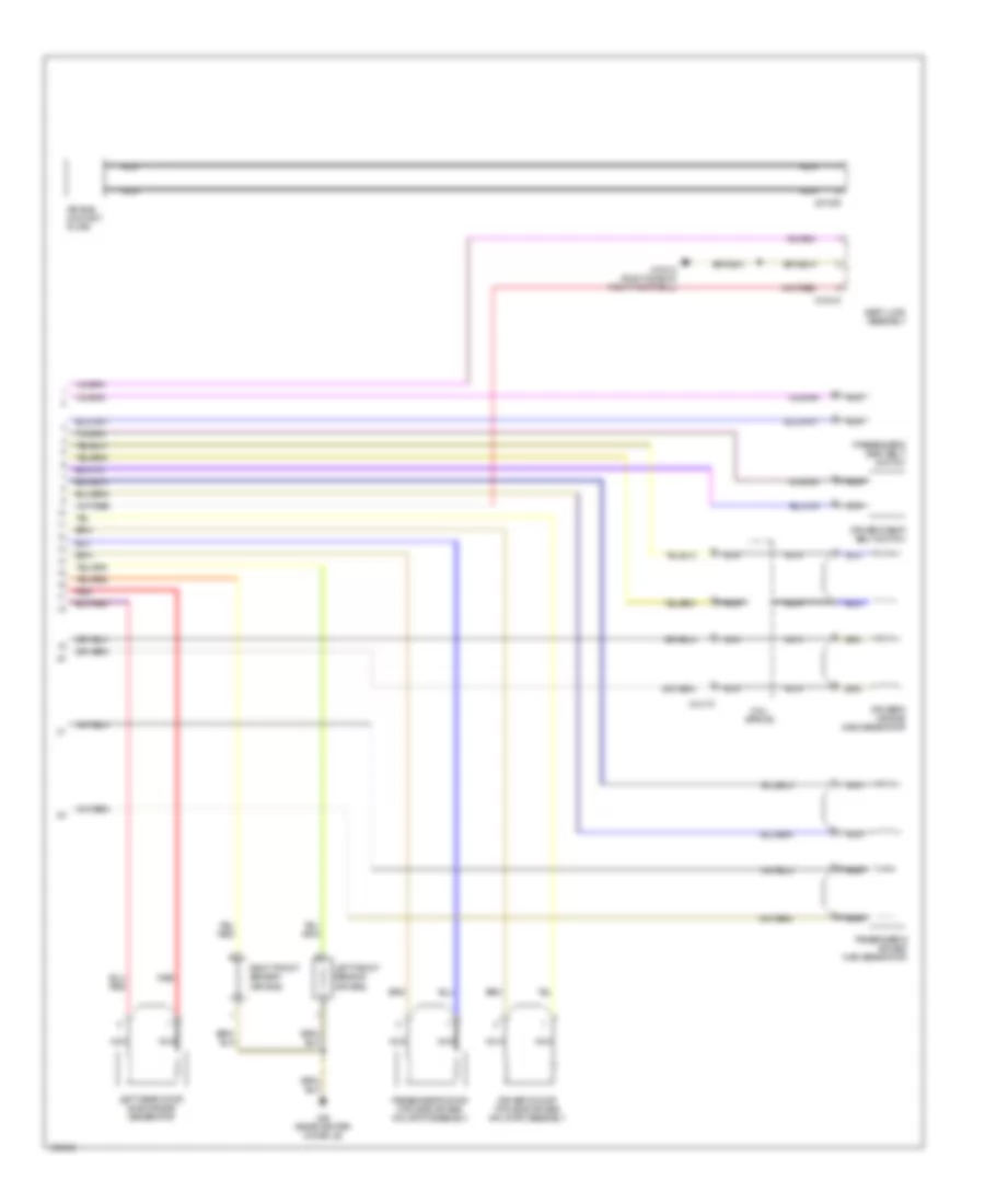
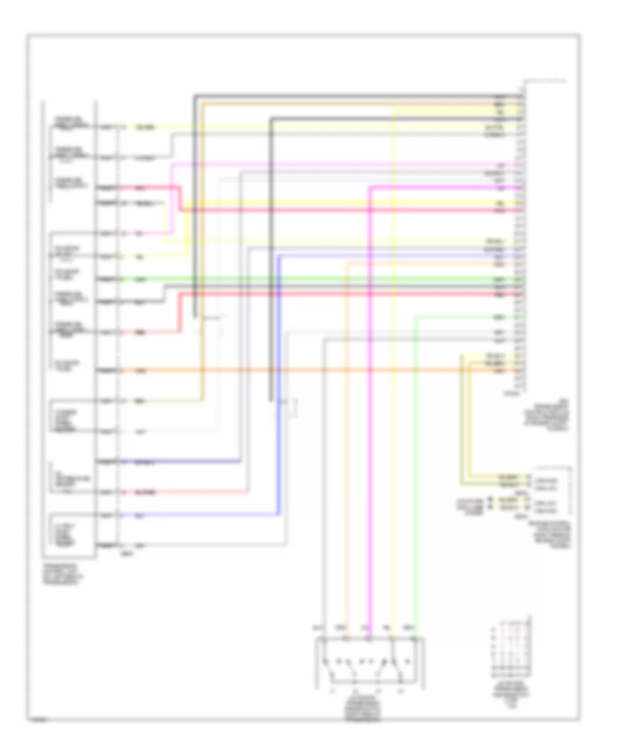
Automatic A/C Wiring Diagram (2 of 2) for BMW 540i 1998
 https://portal-diagnostov.com/license.html
Automotive Electricians Portal FZCO
Automotive Electricians Portal FZCO
https://portal-diagnostov.com/license.html
https://portal-diagnostov.com/license.html
Automotive Electricians Portal FZCO
Automotive Electricians Portal FZCOList of elements for Automatic A/C Wiring Diagram (2 of 2) for BMW 540i 1998:
- Blower motor
- Changeover
- Control module
- Defroster flap motor
- Final stage unit
- Footwell flap actuator
- Footwell/rear compartment actuator motor
- Fresh air flap motor
- Fuse f35 5a
- Fuse f76 40a
- Fuse panel 1
- Fuse panel 6
- Hot at all times
- Hot in run or start
- Left heat exchanger temperature sensor
- Nca
- Output stage rear compartment blower
- Park heating/
- Rear compartment blower motor
- Recirculation flap motor
- Red
- Right heat exchanger temperature sensor
- Shutoff
- Valve
- Valve lws
- Ventilation
- Ventilation flap actuator
- X490 (driver door sill)
ANTI-LOCK BRAKES
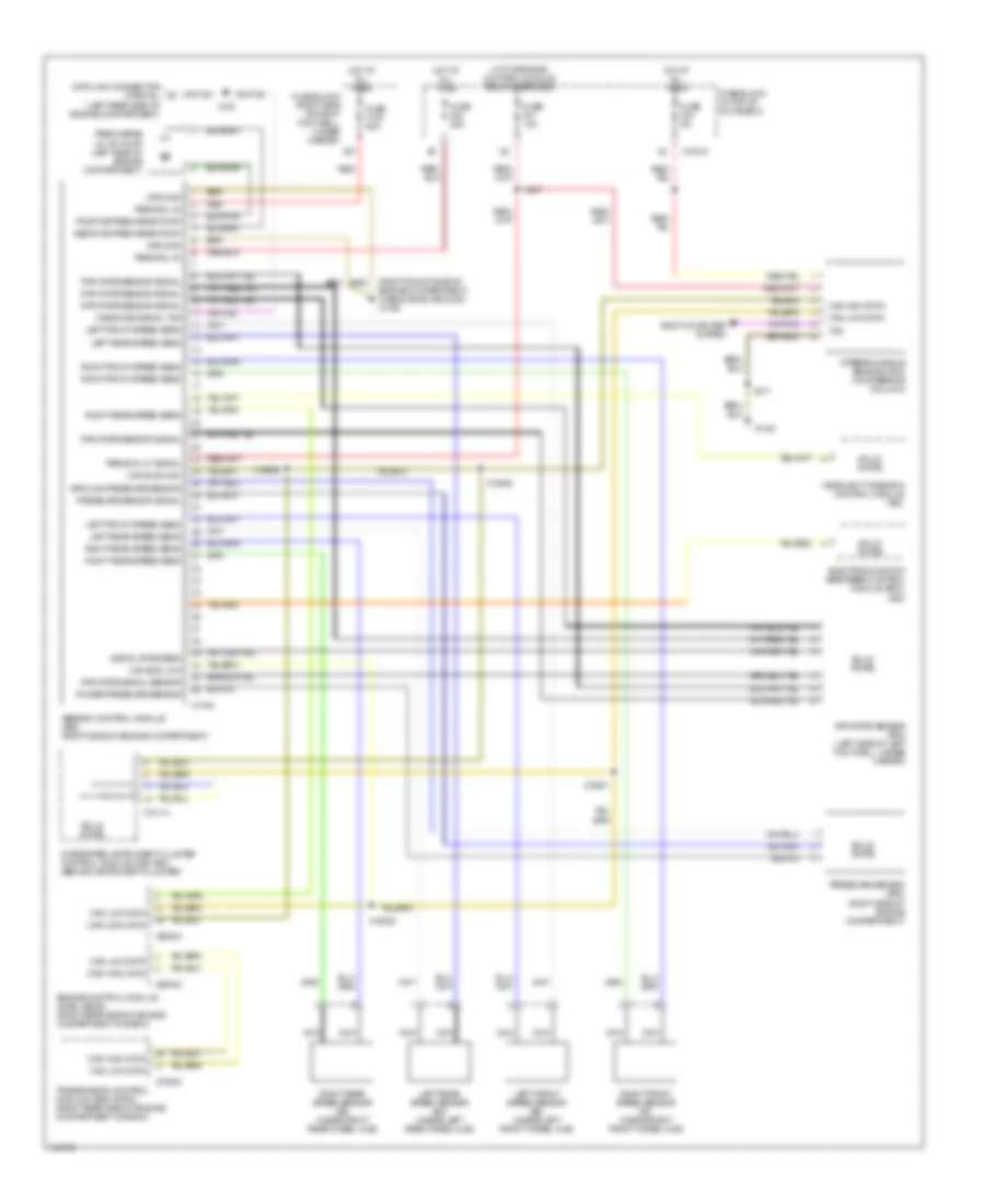
Anti-lock Brakes Wiring Diagram, with Dynamic Stability Control for BMW 540i 1998
 https://portal-diagnostov.com/license.html
Automotive Electricians Portal FZCO
Automotive Electricians Portal FZCO
https://portal-diagnostov.com/license.html
https://portal-diagnostov.com/license.html
Automotive Electricians Portal FZCO
Automotive Electricians Portal FZCOList of elements for Anti-lock Brakes Wiring Diagram, with Dynamic Stability Control for BMW 540i 1998:
- (right front side of engine compartment) (cable shoe ground) x1106
- Abs/dsc control module (a65) (right side of engine compartment)
- Body computer system
- Can bus high
- Can bus low
- Can high data
- Can low data
- Data link connector (partial) (left rear side of engine compartment)
- Diagnosis signal txd
- Electronic shock absorber control module (edc) (a80)
- Engine control module (dme) (a6000) (right rear side of engine compartment in e-box)
- Fuse block (in top of glove box)
- Fuse block (right side of right footwell, under carpet)
- Fuse f108 50a
- Fuse f24 5a
- Fuse f30 25a
- Fuse f31 10a
- Ground
- Ground pressure sensor
- Headlight widening control module (a53)
- Hot at all times
- Hot w/engine control module relay energized
- Integrated instrument cluster control module (ike) (a63) (behind instrument cluster)
- Left front speed sens
- Left front speed sensor (b2) (inside left front wheel hub)
- Left rear speed sens
- Left rear speed sensor (b4) (inside left rear wheel hub)
- Nca
- Positive precharge pump
- Power pressure sensor
- Precharge (m118) pump (left side of engine compartment)
- Pressure sensor (b76) (right side of engine compartment)
- Pressure sensor signal
- Red
- Right front speed sens
- Right front speed sensor (b1) (inside right front wheel hub)
- Right rear speed sens
- Right rear speed sensor (b3) (inside right rear wheel hub)
- Rpm rate sensor (b75) (left side of left footwell, under carpet)
- Rpm rate sensor signal
- Rpm rate signal sensor
- Signal rate sens
- Solid state
- Steering angle sensor (r33) (on steering column)
- Terminal 30
- Terminal 87 signal
- Transmission control module (ags) (a7000) (right rear side of engine compartment in e-box)
- Txd
- X10015
- X10114
- X1108
- X1746
- X183
- X18831
- X18832
- X18835
- X18836
- X217
- X27
- X437
- X60002
- X60004
- X70004
ANTI-THEFT
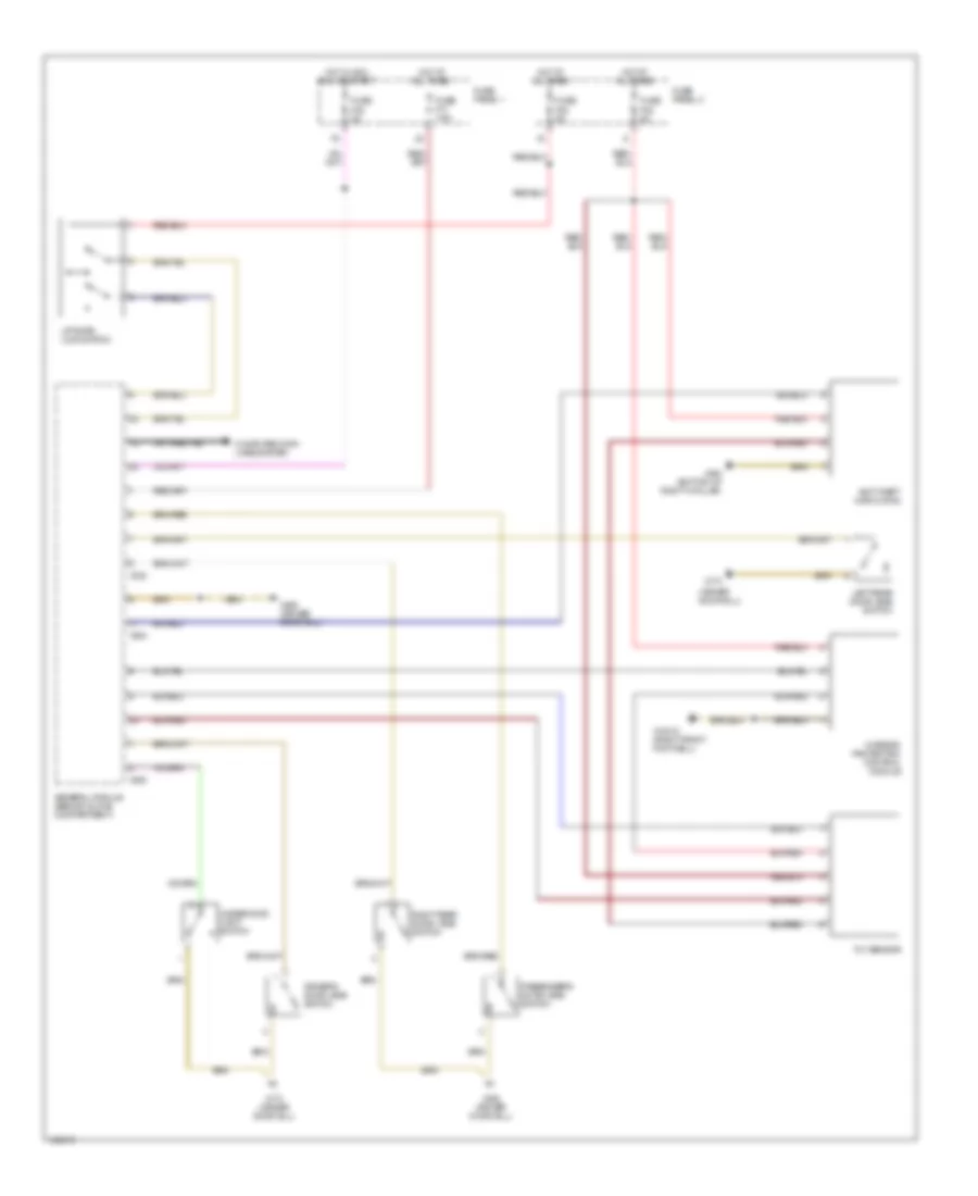
Forced Entry Wiring Diagram for BMW 540i 1998
 https://portal-diagnostov.com/license.html
Automotive Electricians Portal FZCO
Automotive Electricians Portal FZCO
https://portal-diagnostov.com/license.html
https://portal-diagnostov.com/license.html
Automotive Electricians Portal FZCO
Automotive Electricians Portal FZCOList of elements for Forced Entry Wiring Diagram for BMW 540i 1998:
- (driver door sill)
- Anti-theft horn (dwa)
- Computer data lines system
- Driver's door jamb switch
- Fuse f11 7.5a
- Fuse f38 5a
- Fuse f48 5a
- Fuse f53 5a
- Fuse panel 1
- Fuse panel 2
- General module (behind glove compartment)
- Hot at all times
- Hot in acc, run or start
- Interior protection control module
- Left rear door jamb switch
- Liftgate lock switch
- Passenger's door jamb switch
- Right rear door jamb switch
- Tilt sensor
- Underhood light switch
- X10012 (right front footwell)
- X173
- X173 (driver door sill)
- X253
- X254
- X332
- X492 (driver door sill)
- X494 (bottom of right c-pillar)
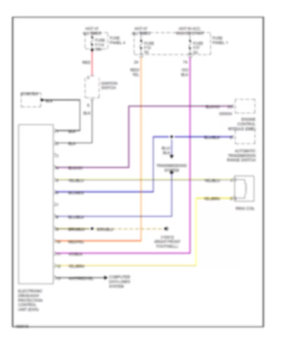
Immobilizer Wiring Diagram for BMW 540i 1998
 https://portal-diagnostov.com/license.html
Automotive Electricians Portal FZCO
Automotive Electricians Portal FZCO
https://portal-diagnostov.com/license.html
https://portal-diagnostov.com/license.html
Automotive Electricians Portal FZCO
Automotive Electricians Portal FZCOList of elements for Immobilizer Wiring Diagram for BMW 540i 1998:
- Automatic transmission range switch
- Computer data lines system
- Electronic driveaway protection control unit (ews)
- Engine control module (dme)
- Fuse f114 50a
- Fuse f12 5a
- Fuse f37 5a
- Fuse panel 1
- Fuse panel 4
- Hot at all times
- Hot in acc, run or start
- Ignition switch
- Red
- Ring coil
- Starter
- Transmissions system
- X10012 (right front footwell)
- X60004
BODY CONTROL MODULES
General Module Wiring Diagram for BMW 540i 1998
 https://portal-diagnostov.com/license.html
Automotive Electricians Portal FZCO
Automotive Electricians Portal FZCO
https://portal-diagnostov.com/license.html
https://portal-diagnostov.com/license.html
Automotive Electricians Portal FZCO
Automotive Electricians Portal FZCOList of elements for General Module Wiring Diagram for BMW 540i 1998:
- Anti-theft system
- Computer data lines system
- Door locks system
- Fuse 20a
- Fuse 30a
- Fuse 5a
- Fuse 7.5a
- Fuse panel 1
- General module (behind glove compartment)
- Hot at all times
- Hot in acc, run or start
- Interior lights system
- Mirrors system
- Power window system
- Power windows system
- Sound systems
- Trunk,tailgate,fuel doors system
- Warning system
- Wiper/washer system
- X10012 (right front footwell)
- X253
- X254
- X332
- X490
- X492 (driver door sill)
COMPUTER DATA LINES
Computer Data Lines Wiring Diagram for BMW 540i 1998
 https://portal-diagnostov.com/license.html
Automotive Electricians Portal FZCO
Automotive Electricians Portal FZCO
https://portal-diagnostov.com/license.html
https://portal-diagnostov.com/license.html
Automotive Electricians Portal FZCO
Automotive Electricians Portal FZCOList of elements for Computer Data Lines Wiring Diagram for BMW 540i 1998:
- (rear left side of engine compt) data link connector
- Abs/asc control module or abs/dsc control module (front of right front shock tower)
- Cruise control module (left side of driver's footwell)
- Electronic shock absorber control module
- Engine control module (rear right side of eng compt, in e-box)
- Fuse block (in glove box top)
- Fuse f114 50a
- Fuse f15 7.5a
- Fuse f25 7.5a
- Fuse f38 5a
- Hot at all times
- Hot in accy, run or start
- Hot in run or start
- Instrument cluster
- Integrated insturment cluster control module (behind instrument cluster)
- Obdii plug (center console)
- Red
- Transmission control module (rear right side of eng compt, in e-box)
- X10
- X10015
- X10113
- X10114
- X1108
- X16
- X166
- X60002
- X60004
- X70001
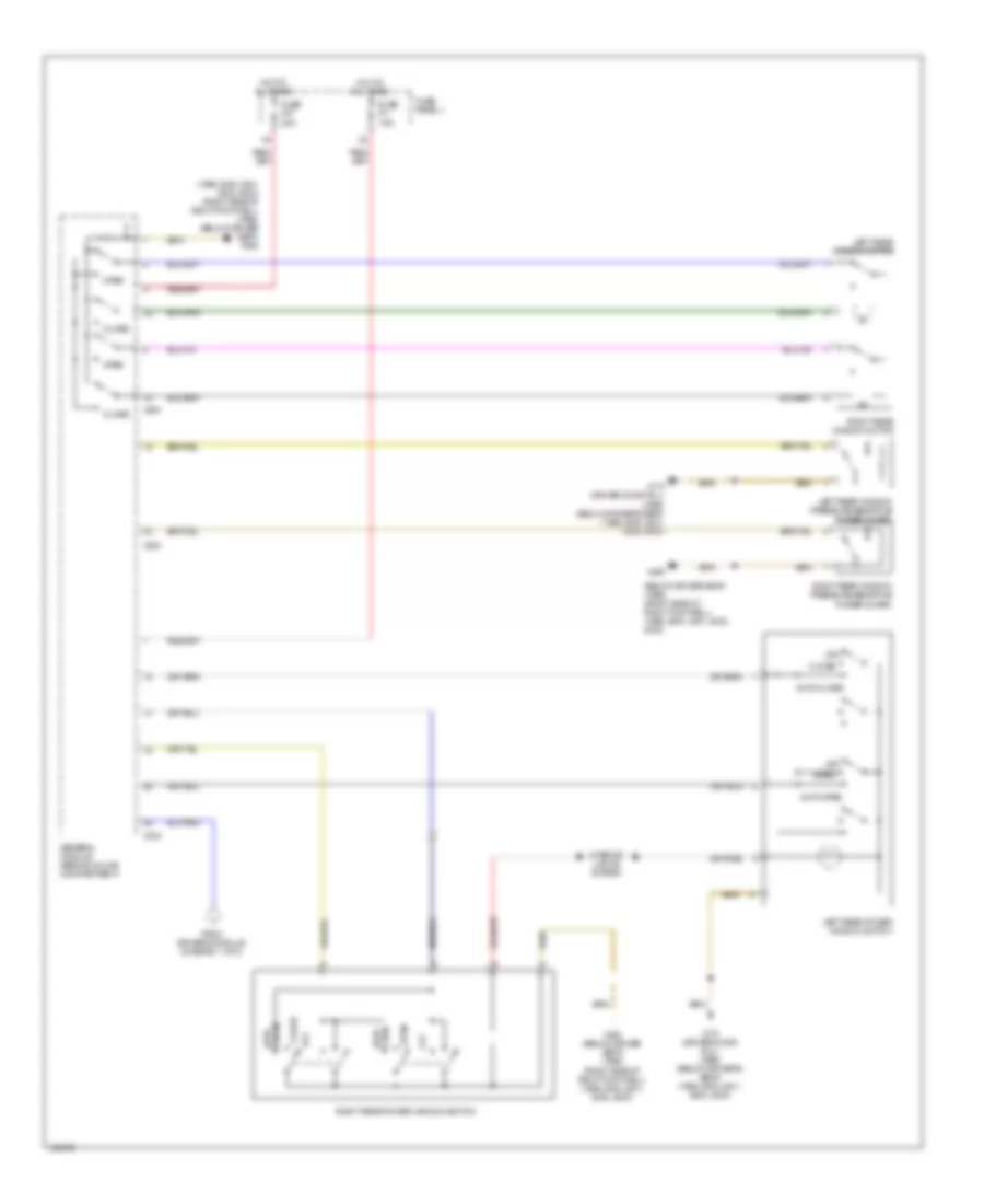
DEFOGGERS
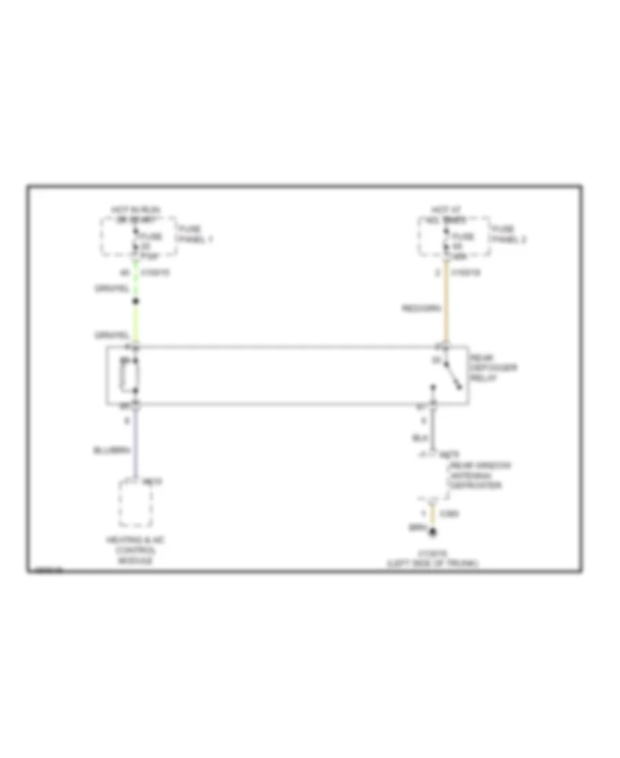
Defoggers Wiring Diagram for BMW 540i 1998
 https://portal-diagnostov.com/license.html
Automotive Electricians Portal FZCO
Automotive Electricians Portal FZCO
https://portal-diagnostov.com/license.html
https://portal-diagnostov.com/license.html
Automotive Electricians Portal FZCO
Automotive Electricians Portal FZCOList of elements for Defoggers Wiring Diagram for BMW 540i 1998:
- Fuse 40a
- Fuse 7.5a
- Fuse panel 1
- Fuse panel 2
- Heating & a/c control module
- Hot at all times
- Hot in run or start
- Rear defogger relay
- Rear window antenna/ defroster
- X10015
- X10019
- X13016 (left side of trunk)
- X379
- X380
- X610
ELECTRONIC SUSPENSION
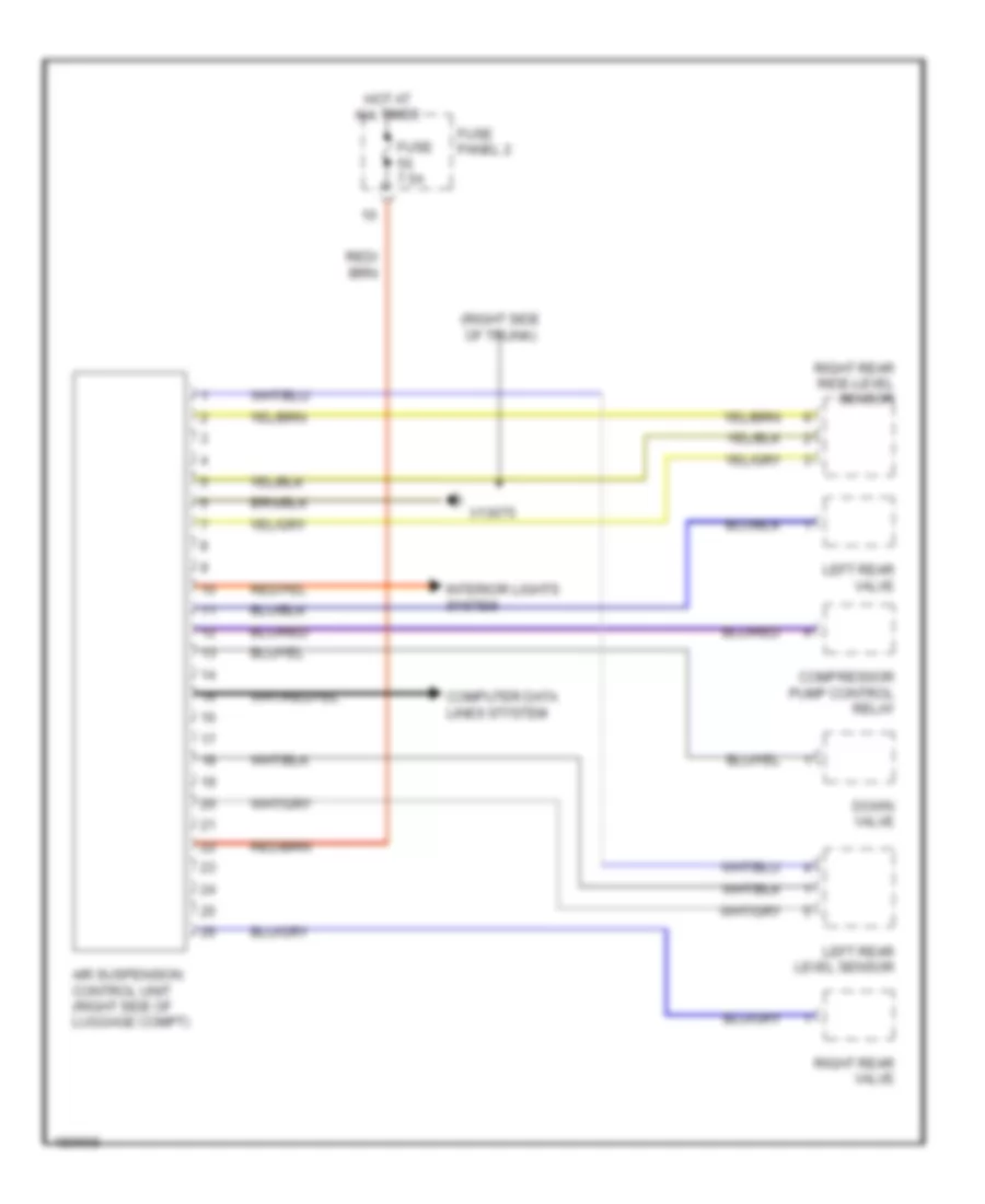
Electronic Air Suspension Wiring Diagram for BMW 540i 1998
 https://portal-diagnostov.com/license.html
Automotive Electricians Portal FZCO
Automotive Electricians Portal FZCO
https://portal-diagnostov.com/license.html
https://portal-diagnostov.com/license.html
Automotive Electricians Portal FZCO
Automotive Electricians Portal FZCOList of elements for Electronic Air Suspension Wiring Diagram for BMW 540i 1998:
- (right side of trunk)
- Air suspension control unit (right side of luggage compt)
- Compressor pump control relay
- Computer data lines stystem
- Down valve
- Fuse 7.5a
- Fuse panel 2
- Hot at all times
- Interior lights system
- Left rear level sensor
- Left rear valve
- Right rear ride-level sensor
- Right rear valve
- X13075
Electronic Damper Control Wiring Diagram for BMW 540i 1998
 https://portal-diagnostov.com/license.html
Automotive Electricians Portal FZCO
Automotive Electricians Portal FZCO
https://portal-diagnostov.com/license.html
https://portal-diagnostov.com/license.html
Automotive Electricians Portal FZCO
Automotive Electricians Portal FZCOList of elements for Electronic Damper Control Wiring Diagram for BMW 540i 1998:
- (right rear of trunk)
- Anti-lock brakes system
- Data link connector
- Electronic shock absorber control module (edc)
- Fuse 15a
- Fuse panel 2
- Hot in run or start
- Left front edc valves
- Left rear edc valves
- Light module
- Nca
- Red
- Right front acceleration sensor
- Right front edc valves
- Right rear acceleration sensor
- Right rear edc valves
- Steering angle sensor
- Switching center
- X263
- X498
- X945
ENGINE PERFORMANCE
4.4L
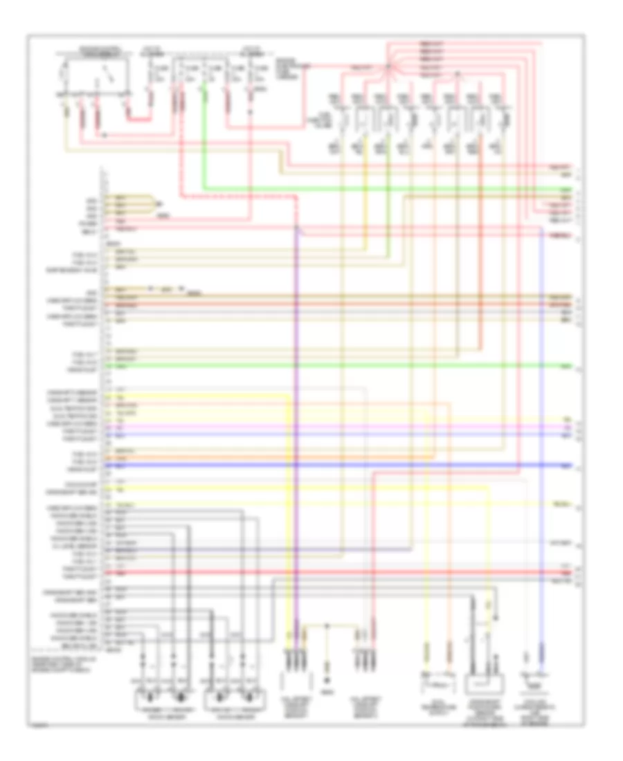
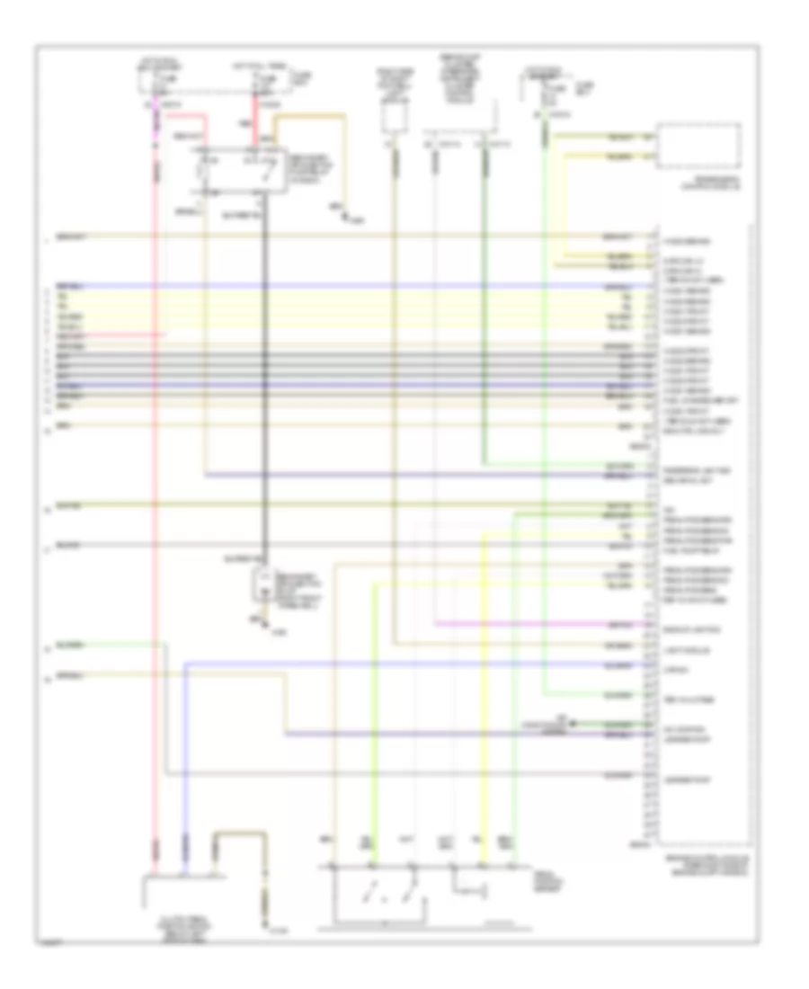
4.4L, Engine Performance Wiring Diagram (1 of 4) for BMW 540i 1998
 https://portal-diagnostov.com/license.html
Automotive Electricians Portal FZCO
Automotive Electricians Portal FZCO
https://portal-diagnostov.com/license.html
https://portal-diagnostov.com/license.html
Automotive Electricians Portal FZCO
Automotive Electricians Portal FZCOList of elements for 4.4L, Engine Performance Wiring Diagram (1 of 4) for BMW 540i 1998:
- Camshaft 1 sensor
- Camshaft 2 sensor
- Cooling characteristic map (right side of engine)
- Cooling map
- Crankshaft position/rpm sensor (on right side of transmission)
- Crankshaft sen
- Crankshaft sen gnd
- Crankshaft sen sig
- Cyl 1-2
- Cyl 3-4
- Cyl 5-6
- Cyl 7-8
- Dual temp sw gnd
- Dual temp sw sig
- Dual temperature switch
- Engine control module (rear right side of engine compt in e-box)
- Engine control module relay
- Engine electronics fuse carrier
- Evap emission valve
- Fuel inj 1
- Fuel inj 2
- Fuel inj 3
- Fuel inj 4
- Fuel inj 5
- Fuel inj 6
- Fuel inj 7
- Fuel inj 8
- Fuel injection valves
- Fuse
- Fuse 30a
- Gnd
- Hall effect camshaft position sensor 1
- Hall effect camshaft position sensor 2
- Hot at all times
- Knock sen 1 sig
- Knock sen 2 sig
- Knock sen 3 sig
- Knock sen 4 sig
- Knock sen shield
- Knock sensor
- Mass air flow sens
- Nca
- Oil level sensor
- Power
- Red
- Sec air inj sig
- Ter 87
- Throttle act
- Vanos inlet
- X60001
- X60003
- X6452
- X6453
- X8582 red
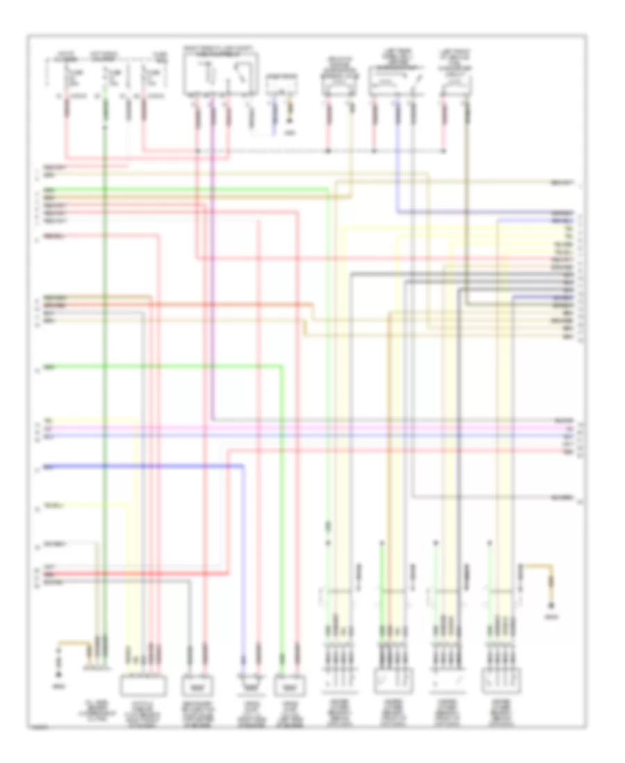
4.4L, Engine Performance Wiring Diagram (2 of 4) for BMW 540i 1998
 https://portal-diagnostov.com/license.html
Automotive Electricians Portal FZCO
Automotive Electricians Portal FZCO
https://portal-diagnostov.com/license.html
https://portal-diagnostov.com/license.html
Automotive Electricians Portal FZCO
Automotive Electricians Portal FZCOList of elements for 4.4L, Engine Performance Wiring Diagram (2 of 4) for BMW 540i 1998:
- (front of engine) evaporative emission valve
- (left front of vehicle) fuel changeover circuit
- (left rear wheelwell) leakage diagnosis pump
- (right side of lugg compt) fuel pump relay
- Fuel pump
- Fuse 10a
- Fuse 25a
- Fuse 7.5a
- Fuse box
- Heated oxygen sensor i (behind cat conv)
- Heated oxygen sensor i (front of cat conv)
- Heated oxygen sensor ii (behind cat conv)
- Heated oxygen sensor ii (front of cat conv)
- Hot at all times
- Hot film mass air flow sensor (right front of engine)
- Hot in run or start
- Nca
- Oil level sensor (underside of oil pan)
- Red
- Secondary air injection pump valve (top center of engine)
- Vanos inlet cyl 1-4 (right side of engine)
- Vanos inlet cyl 5-8 (left side of engine)
- X10015
- X494
- X6452
- X6453
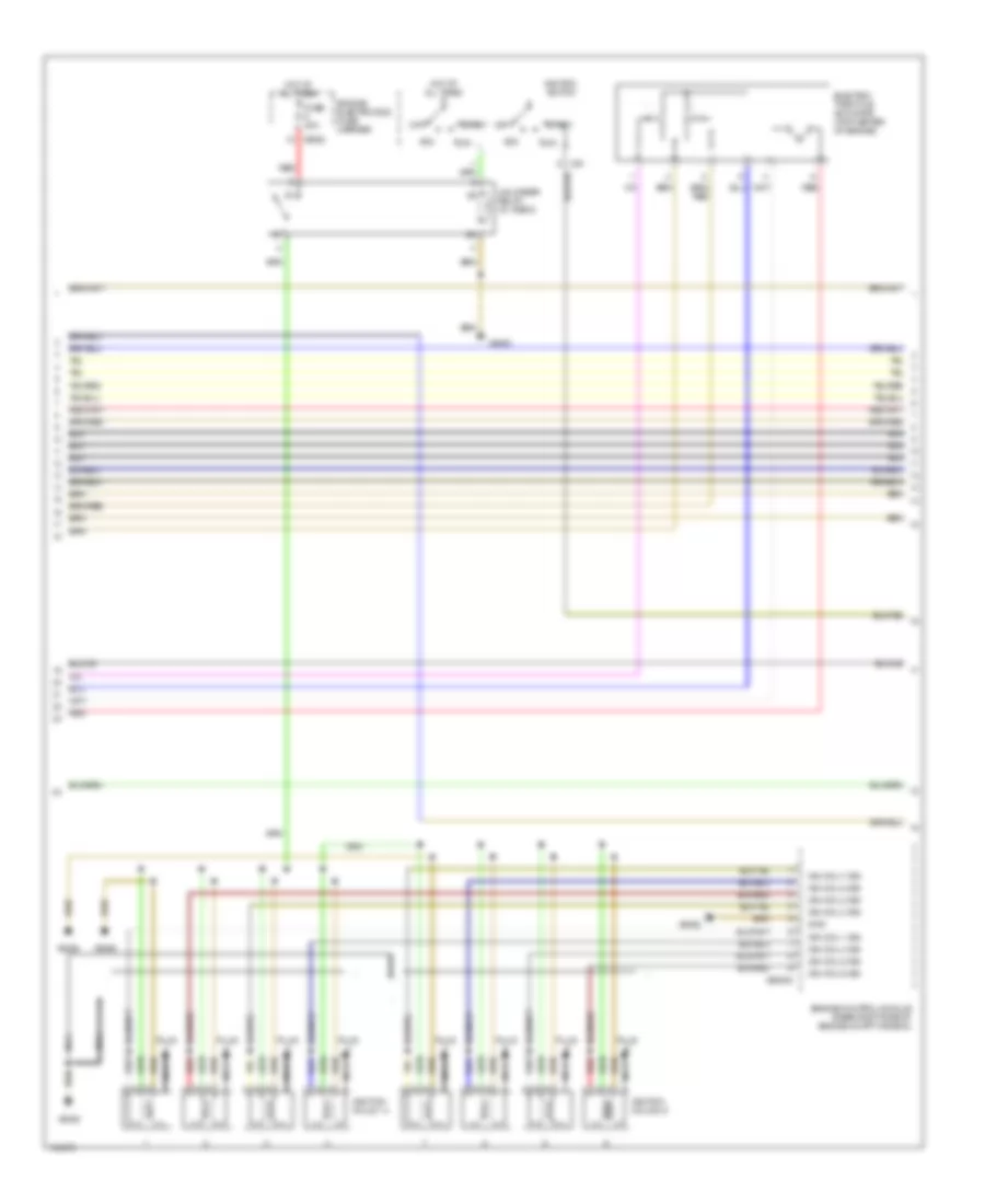
4.4L, Engine Performance Wiring Diagram (3 of 4) for BMW 540i 1998
 https://portal-diagnostov.com/license.html
Automotive Electricians Portal FZCO
Automotive Electricians Portal FZCO
https://portal-diagnostov.com/license.html
https://portal-diagnostov.com/license.html
Automotive Electricians Portal FZCO
Automotive Electricians Portal FZCOList of elements for 4.4L, Engine Performance Wiring Diagram (3 of 4) for BMW 540i 1998:
- Acc
- Electric throttle actuator (top center of engine)
- Engine control module (rear right side of engine compt in e-box)
- Engine electronics fuse carrier
- Fuse 30a
- Gnd
- Hot at all times
- Ign coil 1 sig
- Ign coil 2 sig
- Ign coil 3 sig
- Ign coil 4 sig
- Ign coil 5 sig
- Ign coil 6 sig
- Ign coil 7 sig
- Ign coil 8 sig
- Ignition coils 1-4
- Ignition coils 5-8
- Ignition switch
- Nca
- Off
- Plug
- Red
- Run
- Start
- Unloader relay (in e box)
- X33
- X60005
- X6452
- X6453
- X6455
- X6456
- X8582
4.4L, Engine Performance Wiring Diagram (4 of 4) for BMW 540i 1998
 https://portal-diagnostov.com/license.html
Automotive Electricians Portal FZCO
Automotive Electricians Portal FZCO
https://portal-diagnostov.com/license.html
https://portal-diagnostov.com/license.html
Automotive Electricians Portal FZCO
Automotive Electricians Portal FZCOList of elements for 4.4L, Engine Performance Wiring Diagram (4 of 4) for BMW 540i 1998:
- (behind inst cluster) integrated instrument cluster control module
- (right side of right footwell) light module
- (ter 15-16 not used)
- (ter 20-22 not used)
- (ter 5-6 not used)
- 87a
- A/c comp sig
- Air conditioning system
- Backup light sig
- Clutch pedal position switch (below left side of dash)
- Cpp sw
- Data can hi
- Data can lo
- Eng ctrl mod rly
- Engine control module (rear right side of engine compt in e-box)
- Fuel changeover crt
- Fuel pump relay
- Fuse 50a
- Fuse 5a
- Fuse box
- Ho2s 1 behind
- Ho2s 1 front
- Ho2s 2 behind
- Ho2s 2 front
- Hot at all times
- Hot in run or start
- Hot in run, acc or start
- Ign
- Leakage pump
- Light module
- Pedal pos sens
- Pedal pos sens pwr
- Pedal pos sens sig
- Pedal position sensor
- Red
- Reversing light sig
- Sec air inj act
- Secondary air injection pump (right front wheelwell)
- Secondary air injection pump relay (in e box)
- Ter 15 vlotage
- Transmission control module
- X10015
- X10113
- X10114
- X1108
- X13030
- X166
- X490
- X60002
- X60004
EXTERIOR LIGHTS
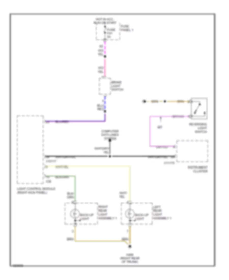
Backup Lamps Wiring Diagram for BMW 540i 1998
 https://portal-diagnostov.com/license.html
Automotive Electricians Portal FZCO
Automotive Electricians Portal FZCO
https://portal-diagnostov.com/license.html
https://portal-diagnostov.com/license.html
Automotive Electricians Portal FZCO
Automotive Electricians Portal FZCOList of elements for Backup Lamps Wiring Diagram for BMW 540i 1998:
- Back-up light
- Brake light switch
- Computer data lines system
- Fuse f41 5a
- Fuse panel 1
- Hot in acc, run or start
- Instrument cluster
- Left rear light assembly 1
- Light control module (right kick panel)
- M/t
- Reversing light switch
- Right rear light assembly 1
- X10117
- X11176
- X38
- X498 (right rear of trunk)
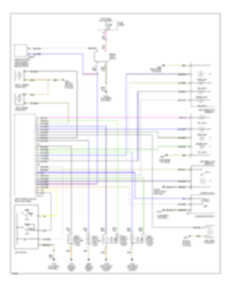
Exterior Lamps Wiring Diagram for BMW 540i 1998
 https://portal-diagnostov.com/license.html
Automotive Electricians Portal FZCO
Automotive Electricians Portal FZCO
https://portal-diagnostov.com/license.html
https://portal-diagnostov.com/license.html
Automotive Electricians Portal FZCO
Automotive Electricians Portal FZCOList of elements for Exterior Lamps Wiring Diagram for BMW 540i 1998:
- (bottom of right c-pillar)
- (in driver's footwell)
- (right rear of trunk)
- Brake light
- Brake light switch
- Combination switch
- Engine control module (dme) (right rear of engine compt)
- Fuse f41 5a
- Fuse panel 1
- Hazard switch
- Head
- High level stoplight
- Hot in acc, run or start
- Left
- Left front auxiliary turn light
- Left front turn signal lamp
- Left license plate light
- Left rear light assembly 1
- Light control module (right kick panel)
- Light switch
- Off
- Park
- Right
- Right front auxiliary turn light
- Right front turn signal lamp
- Right license plate light
- Right rear light assembly 1
- Tail light
- Turn
- Turn light
- X10012 (right front footwell)
- X10117
- X1106 (right front of engine compt)
- X1108
- X1108 (in driver's footwell)
- X12
- X151 (below driver's seat)
- X165 (left front of engine compt)
- X32
- X38
- X490 (below driver's seat)
- X494
- X494 (bottom of right c-pillar)
- X498
- X498 (right rear of trunk)
- X60004
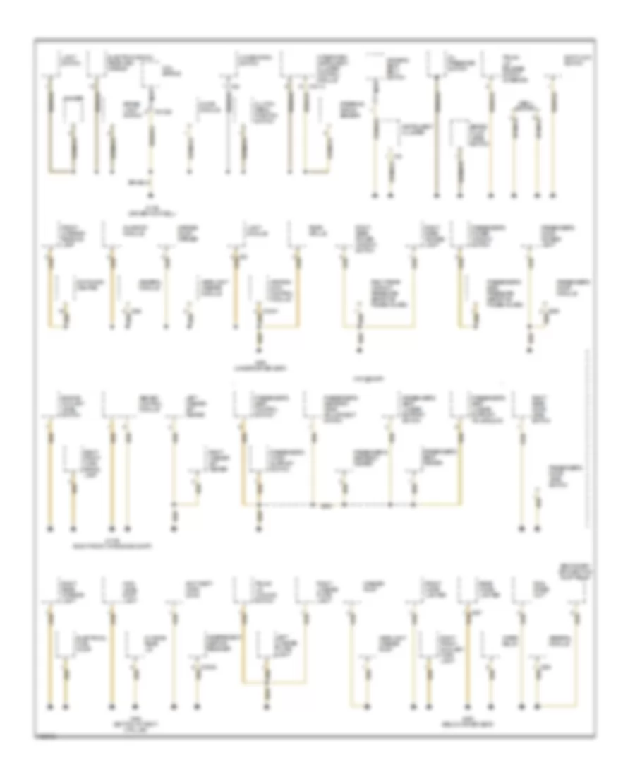
GROUND DISTRIBUTION
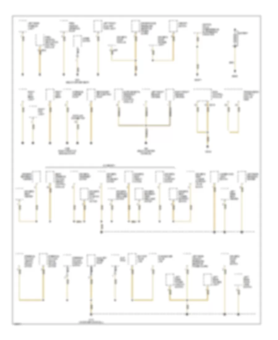
Ground Distribution Wiring Diagram (1 of 3) for BMW 540i 1998
 https://portal-diagnostov.com/license.html
Automotive Electricians Portal FZCO
Automotive Electricians Portal FZCO
https://portal-diagnostov.com/license.html
https://portal-diagnostov.com/license.html
Automotive Electricians Portal FZCO
Automotive Electricians Portal FZCOList of elements for Ground Distribution Wiring Diagram (1 of 3) for BMW 540i 1998:
- Auxiliary water pump
- Battery
- Changeover valve lws
- Data link connector
- Dde control module
- Driver's door access light
- Driver's door jamb switch
- Driver's door module
- Driver's headrest motor
- Driver's seat cushion tilt motor
- Driver's seat heater
- Driver's seat height motor
- Driver's seat lumbar support switch
- Driver's seat lumbar support valve block
- Driver's seat movement motor
- Driver's seatback head recliner motor
- Driver's seatback heater
- Driver's seatback recliner motor
- Driver's side pressure sensitive finger guard
- Driver's thigh support motor
- Ignition coils interference suppression capacitor
- Intensive washer pump
- Left front auxiliary turn light
- Left front sensor (air bag)
- Left rear access light
- Left rear door jamb switch
- Left rear interior light
- Left rear power window switch
- Left rear seat heater
- Left rear seatback heater
- Left rear window pressure sensitive finger guard
- Memory switch
- Nca
- Park heating metering pump
- Park heating/ ventilation control module
- Right fog light
- Right front sensor (air bag)
- Right high beam
- Right low beam light
- Seat/ steering column memory control module
- Secondary air injection pump
- Shutoff valve lws
- Slip ring
- Steering column angle adjust motor
- Steering column length adjust motor
- Steering column position switch
- Transmission control module (ags)
- Underhood light switch
- W/ memory
- Wiper motor
- X151 (below driver seat)
- X166 (right front of engine compt)
- X173 (on driver door sill)
- X2019
- X2042
- X46 (below center console)
- X6406
- X64571
Ground Distribution Wiring Diagram (2 of 3) for BMW 540i 1998
 https://portal-diagnostov.com/license.html
Automotive Electricians Portal FZCO
Automotive Electricians Portal FZCO
https://portal-diagnostov.com/license.html
https://portal-diagnostov.com/license.html
Automotive Electricians Portal FZCO
Automotive Electricians Portal FZCOList of elements for Ground Distribution Wiring Diagram (2 of 3) for BMW 540i 1998:
- Abs/asc control module
- Anti-theft horn (dwa)
- Brake fluid level switch
- Brake light switch
- Chime module
- Clutch pedal position switch
- Coil spring
- Combination switch
- Dimmer
- Driver's seat belt switch
- Electrical fuel pump
- Electrochromic rear view mirror
- Engine coolant level switch
- Final stage unit
- Front cigar lighter
- Front interior/ reading lamp
- Garage door opener
- General module
- Headlight washer module
- Headlight washer pump
- Heating & a/c control module
- High level stop light
- Independent heating receiver
- Instrument cluster
- Integrated instrument cluster control module
- Left license plate light
- Left washer jet heater
- Light module
- Light switch
- Nca
- Obd ii socket
- Oil pressure switch
- Passenger's door access light
- Passenger's door jamb switch
- Passenger's door module
- Passenger's power window switch
- Passenger's seat control switch
- Passenger's seat heater
- Passenger's seat lumbar support switch
- Passenger's seat lumbar support valve block
- Passenger's seatback head adjustment switch
- Passenger's seatback heater
- Passenger's side pressure sensitive finger guard
- Passenger's thigh support switch
- Rear cigar lighter
- Rear grille
- Right front auxiliary turn light
- Right front turn signal lamp
- Right license plate light
- Right rear access light
- Right rear door jamb switch
- Right rear interior light
- Right rear power window switch
- Right rear window pressure sensitive finger guard
- Right washer jet heater
- Secondary air injection pump relay
- Shiftlock switch
- Steering angle sensor
- Sunroof module
- Switching centre
- Trunk lid locking switch
- Trunk lid release switch (interior)
- W/o memory
- Washer pump
- Wiper relay
- X01026
- X10113
- X1106 (right front of engine compt)
- X1108 (driver footwell)
- X16
- X18830
- X254
- X32
- X490 (below driver seat)
- X492 (under driver seat)
- X494 (bottom of right c-pillar)
- X889
- Zv drive rear lid
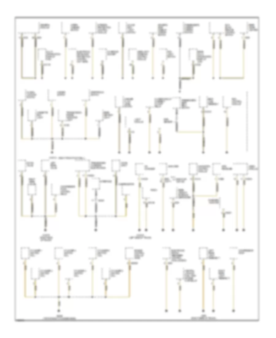
Ground Distribution Wiring Diagram (3 of 3) for BMW 540i 1998
 https://portal-diagnostov.com/license.html
Automotive Electricians Portal FZCO
Automotive Electricians Portal FZCO
https://portal-diagnostov.com/license.html
https://portal-diagnostov.com/license.html
Automotive Electricians Portal FZCO
Automotive Electricians Portal FZCOList of elements for Ground Distribution Wiring Diagram (3 of 3) for BMW 540i 1998:
- (right front footwell)
- Amplifier
- Cassette box light
- Cd changer
- Central locking fuel tank access flap relay
- Charging socket
- Closedcircuit current cutoff relay
- Compensator
- Compressor pump
- Compressor pump control relay
- Cylinder 1 ignition coil
- Cylinder 2 ignition coil
- Cylinder 3 ignition coil
- Cylinder 4 ignition coil
- Cylinder 5 ignition coil
- Cylinder 6 ignition coil
- Down valve
- Driver's side makeup mirror switch
- Electronic drive away protection control unit (ews)
- Electronic shock absorber control module (edc)
- Engine control module (dme)
- Fog light switch
- General module
- Global locking switch
- Glove box light switch
- Gps receiver
- Hazard switch
- Headlight widening control module
- Interface
- Interior protection control module
- Left rear light assembly i
- Left rear valve
- Light module
- Multi- information display (mid)
- Navigation control module
- Nca
- Onboard monitor
- Passenger's makeup mirror switch
- Passenger's seat belt switch
- Radio
- Radio/hifi top hifi
- Rain sensor
- Rdc control module
- Rear ashtray light
- Rear cigar lighter
- Rear multi information display (mid)
- Rear window antenna/ defroster
- Right rear light assembly i
- Right rear valve
- Seat load assembly
- Steptronic switch
- Sun blind remote control switch
- Transceiver/ charging electronics
- Transmission range indicator light
- Video module
- Voice input
- Washer fluid level switch
- Wiper/ washer switch
- X10012
- X10218
- X1193
- X12
- X13016 (left side of trunk)
- X13075 (right side of trunk)
- X1313
- X18180
- X18500
- X18771
- X18804
- X1958
- X263
- X386
- X4545
- X498 (right rear of trunk)
- X60005
- X6456 (top of right cylinder head)
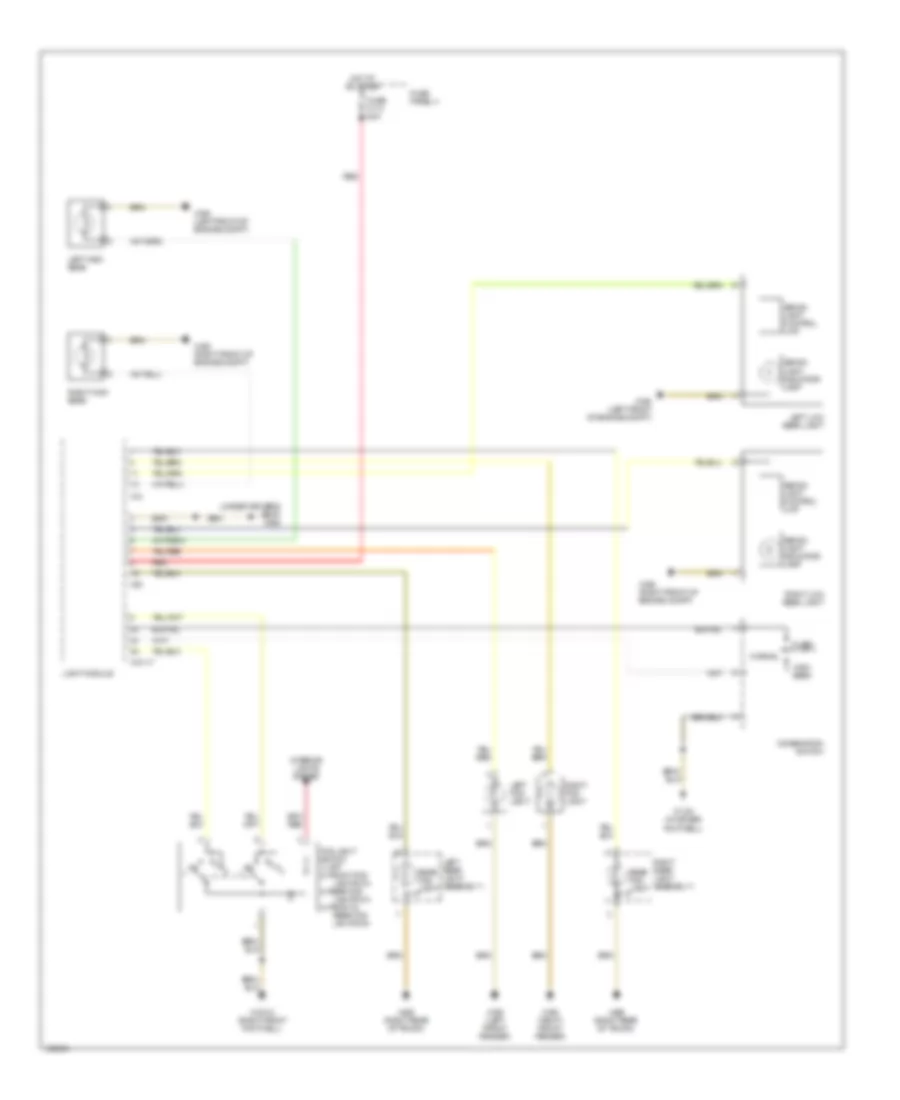
HEADLIGHTS
Headlamps & Fog Lamps Wiring Diagram for BMW 540i 1998
 https://portal-diagnostov.com/license.html
Automotive Electricians Portal FZCO
Automotive Electricians Portal FZCO
https://portal-diagnostov.com/license.html
https://portal-diagnostov.com/license.html
Automotive Electricians Portal FZCO
Automotive Electricians Portal FZCOList of elements for Headlamps & Fog Lamps Wiring Diagram for BMW 540i 1998:
- (under driver's seat) x492
- 3) rear fog
- 4) front &
- Combination switch
- Flash
- Fog light switch 1) off 2) front fog
- Fuse f113 80a
- Fuse panel 4
- High beam
- Hot at all times
- Interior lights system
- Left fog light
- Left high beam
- Left low beam light
- Left rear light assembly 1
- Light module
- Lights on
- Normal
- Rear fog light
- Rear fog lights on
- Red
- Right fog light
- Right high beam
- Right low beam light
- Right rear light assembly 1
- X10012 (right front footwell)
- X10117
- X1108 (in driver footwell)
- X12
- X165 (left front fender)
- X165 (left front of engine compt)
- X166 (right front fender)
- X166 (right front of engine compt)
- X38
- X498 (right rear of trunk)
- Xenon light control unit
- Xenon light indicator lamp
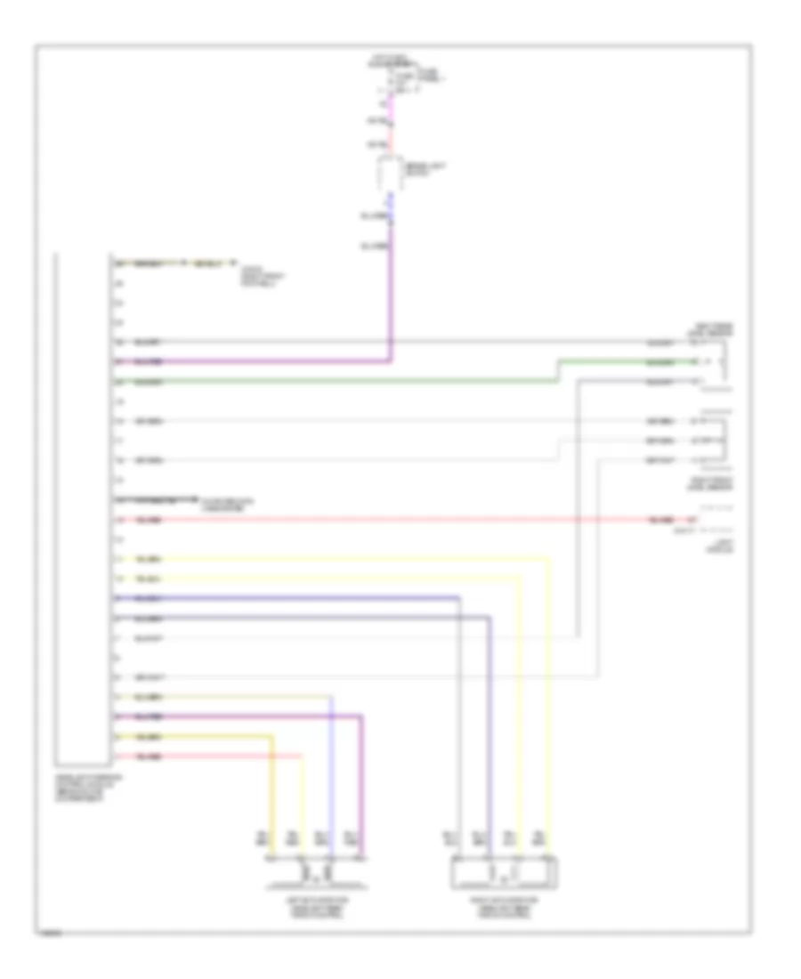
Headlamps Leveling Wiring Diagram for BMW 540i 1998
 https://portal-diagnostov.com/license.html
Automotive Electricians Portal FZCO
Automotive Electricians Portal FZCO
https://portal-diagnostov.com/license.html
https://portal-diagnostov.com/license.html
Automotive Electricians Portal FZCO
Automotive Electricians Portal FZCOList of elements for Headlamps Leveling Wiring Diagram for BMW 540i 1998:
- Brake light switch
- Computer data lines system
- Fuse f41 5a
- Fuse panel 1
- Headlight widening control module (behind glove compartment)
- Hot in acc, run or start
- Left actuator for headlight beam throw control
- Light module
- Right actuator for headlight beam throw control
- Right front level sensor
- Right rear level sensor
- X10012 (right front footwell)
- X10117
HORN
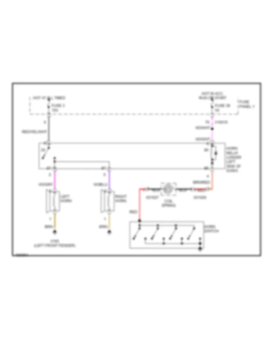
Horn Wiring Diagram for BMW 540i 1998
 https://portal-diagnostov.com/license.html
Automotive Electricians Portal FZCO
Automotive Electricians Portal FZCO
https://portal-diagnostov.com/license.html
https://portal-diagnostov.com/license.html
Automotive Electricians Portal FZCO
Automotive Electricians Portal FZCOList of elements for Horn Wiring Diagram for BMW 540i 1998:
- Coil spring
- Fuse 3 15a
- Fuse 38 5a
- Fuse panel 1
- Horn relay (under left side of dash)
- Horn switch
- Hot at all times
- Hot in acc, run or start
- Left horn
- Nca
- Red
- Right horn
- X01026
- X01027
- X10015
- X165 (left front fender)
INSTRUMENT CLUSTER
Instrument Cluster Wiring Diagram, with IKE for BMW 540i 1998
 https://portal-diagnostov.com/license.html
Automotive Electricians Portal FZCO
Automotive Electricians Portal FZCO
https://portal-diagnostov.com/license.html
https://portal-diagnostov.com/license.html
Automotive Electricians Portal FZCO
Automotive Electricians Portal FZCOList of elements for Instrument Cluster Wiring Diagram, with IKE for BMW 540i 1998:
- (2.8l)
- (4.4l)
- Anti-lock brakes system
- Computer data lines system
- Electrical fuel pump
- Engine controls system
- Exterior lights system
- Fuel level sensor
- Fuse 5a
- Fuse panel 1
- Gong
- Hot at all times
- Hot in acc, run or start
- Hot in run or start
- Integrated instrument cluster control module
- Left front brake pad sensor
- Right rear brake pad sensor
- Temperature sensor
- X10113
- X10114
- X1108 (in driver's footwell)
- X518
- X522
- X638
- X679
- X770
Instrument Cluster Wiring Diagram, without IKE for BMW 540i 1998
 https://portal-diagnostov.com/license.html
Automotive Electricians Portal FZCO
Automotive Electricians Portal FZCO
https://portal-diagnostov.com/license.html
https://portal-diagnostov.com/license.html
Automotive Electricians Portal FZCO
Automotive Electricians Portal FZCOList of elements for Instrument Cluster Wiring Diagram, without IKE for BMW 540i 1998:
- (2.8l)
- (4.4l)
- (diver's footwell)
- (diver's footwell) x1108
- Anti-lock brakes system
- Combination switch
- Computer data lines system
- Electrical fuel pump
- Engine controls system
- Fuel level sensor i
- Fuel level sensor ii
- Fuse 5a
- Fuse fuse 5a
- Fuse panel 1
- Hot at all times
- Hot in acc, run or start
- Hot in run or start
- Instrument cluster
- Interior lights system
- Left front brake pad sensor
- Starting/charging system
- Temperature sensor
- X1108
- X11175
- X11176
- X16
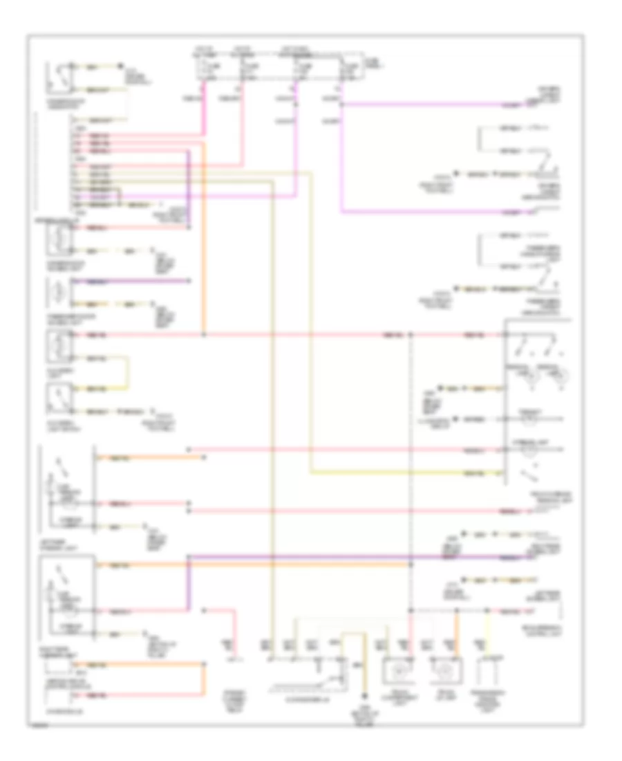
INTERIOR LIGHTS
Courtesy Lamps Wiring Diagram for BMW 540i 1998
 https://portal-diagnostov.com/license.html
Automotive Electricians Portal FZCO
Automotive Electricians Portal FZCO
https://portal-diagnostov.com/license.html
https://portal-diagnostov.com/license.html
Automotive Electricians Portal FZCO
Automotive Electricians Portal FZCOList of elements for Courtesy Lamps Wiring Diagram for BMW 540i 1998:
- (below driver seat)
- (driver door sill)
- (right front footwell)
- Air suspension control unit
- Chime module
- Driver's
- Driver's door access light
- Driver's door jamb switch
- Driver's makeup mirror light
- Front interior/ reading lamp
- Fuse f11 7.5a
- Fuse f38 5a
- Fuse f39 7.5a
- Fuse f4 20a
- Fuse panel 1
- General module
- Glove box light
- Glove box light switch
- Heating and a/c control module
- Hot at all times
- Hot in acc, run or start
- Illumination circuit
- Interior lamp
- Interior light
- Left rear access light
- Left rear interior light
- Makeup mirror switch
- Map reading light
- Passenger's door access light
- Passenger's makeup mirror light
- Passenger's makeup mirror switch
- Reading lamp
- Right rear access light
- Right rear interior light
- Standby current cutoff relay
- Toplight
- Transmission range indicator light
- Trunk compartment light
- Trunk lid lamp
- X10012
- X10012 (right front footwell)
- X1193
- X151 (below driver seat)
- X173
- X173 (driver door sill)
- X253
- X254
- X332
- X492
- X492 (below driver seat)
- X494 (bottom of right c- pillar)
- X610
- Zv drive rear lid
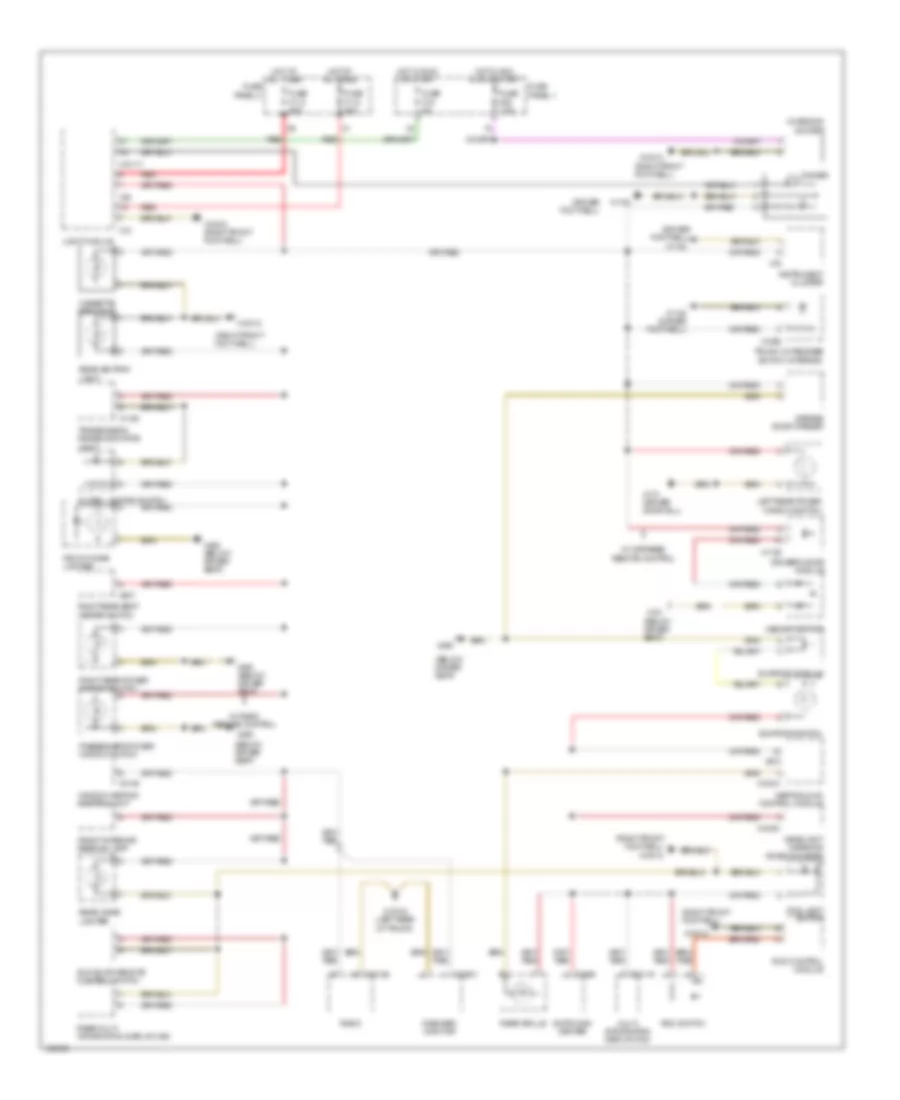
Instrument Illumination Wiring Diagram for BMW 540i 1998
 https://portal-diagnostov.com/license.html
Automotive Electricians Portal FZCO
Automotive Electricians Portal FZCO
https://portal-diagnostov.com/license.html
https://portal-diagnostov.com/license.html
Automotive Electricians Portal FZCO
Automotive Electricians Portal FZCOList of elements for Instrument Illumination Wiring Diagram for BMW 540i 1998:
- (below driver seat)
- (driver footwell)
- (right front footwell)
- Cassette box light
- Charging socket
- Dimmer
- Driver's door module
- Fog light switch
- Front cigar lighter
- Front interior/ reading lamp
- Fuse f112 80a
- Fuse f113 80a
- Fuse f16 5a
- Fuse f39 7.5a
- Fuse panel 1
- Fuse panel 4
- Garage door opener
- Global locking switch
- Headlight widening potentiometer
- Heating & a/c control module
- Hot at all times
- Hot in acc, run or start
- Hot in run or start
- Instrument cluster
- Left rear power window switch
- Light module
- Memory switch
- Multi information display (mid)
- Onboard monitor
- Passenger's power window switch
- Radio
- Rdc control module
- Rdc switch
- Rear ashtray light
- Rear cigar lighter
- Rear grille
- Rear multi information display (mid)
- Red
- Right rear power window switch
- Right rear seat heater switch
- Sun blind remote control switch
- Sunroof module
- Sunroof switch
- Switching center
- Transmission range indicator light
- Trunk lid release switch (interior)
- W/ infrared remote control
- W/ radio remote control
- Window heating control unit
- X10012
- X10012 (right front footwell)
- X10051
- X10117
- X10119
- X1108
- X1108 (driver footwell)
- X1129
- X1193
- X12
- X1295
- X13016 (left rear of trunk)
- X151
- X16
- X173 (driver door sill)
- X18126
- X18341
- X1869
- X18801
- X3146
- X38
- X490 (below driver seat)
- X492
- X492 (below driver seat)
- X610
- X637
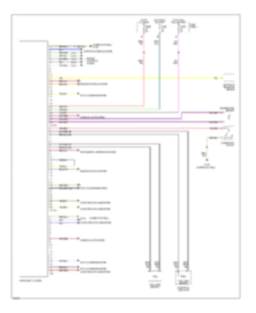
MEMORY SYSTEMS
Driver"s Memory Seat Wiring Diagram for BMW 540i 1998
 https://portal-diagnostov.com/license.html
Automotive Electricians Portal FZCO
Automotive Electricians Portal FZCO
https://portal-diagnostov.com/license.html
https://portal-diagnostov.com/license.html
Automotive Electricians Portal FZCO
Automotive Electricians Portal FZCOList of elements for Driver"s Memory Seat Wiring Diagram for BMW 540i 1998:
- (below driver seat)
- (driver door sill)
- (driver door sill) x173
- Back
- Backward
- Computer data lines system
- Driver's door module
- Driver's headrest motor
- Driver's seat back head recliner motor
- Driver's seat back recliner motor
- Driver's seat cushion tilt motor
- Driver's seat height motor
- Driver's seat movement motor
- Driver's setback head adjustment switch
- Driver's thigh support motor
- Driver's thigh support switch
- Forward
- Front
- Fuse f13 30a
- Fuse f29 30a
- Fuse panel 1
- Hot at all times
- Interior lights system
- Mem 1
- Mem 2
- Mem 3
- Memory switch
- Off
- Program
- Seat/steering column memory control module (under driver seat)
- Steering column adjustment circuit
- X1129
- X151
- X173
- X173 (driver door sill)
- X887
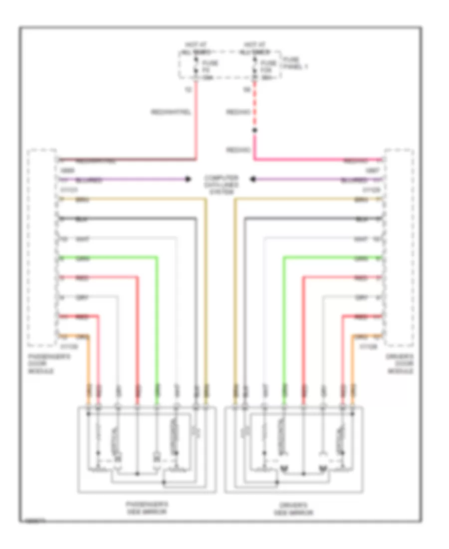
Memory Mirrors Wiring Diagram for BMW 540i 1998
 https://portal-diagnostov.com/license.html
Automotive Electricians Portal FZCO
Automotive Electricians Portal FZCO
https://portal-diagnostov.com/license.html
https://portal-diagnostov.com/license.html
Automotive Electricians Portal FZCO
Automotive Electricians Portal FZCOList of elements for Memory Mirrors Wiring Diagram for BMW 540i 1998:
- Computer data lines system
- Driver's door module
- Driver's side mirror
- Fuse f29 30a
- Fuse f6 30a
- Fuse panel 1
- Horizontal
- Hot at all times
- Passenger's door module
- Passenger's side mirror
- Red
- Vertical
- X1128
- X1129
- X1130
- X1131
- X887
- X889
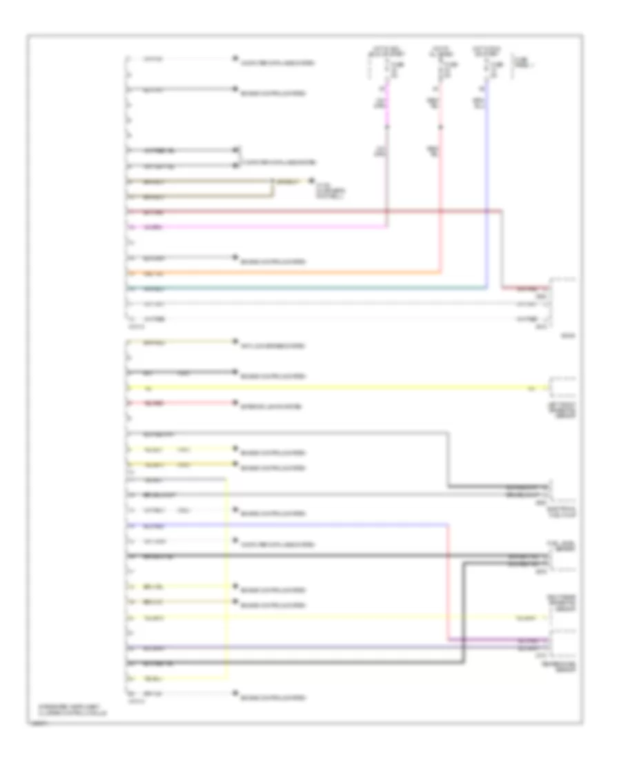
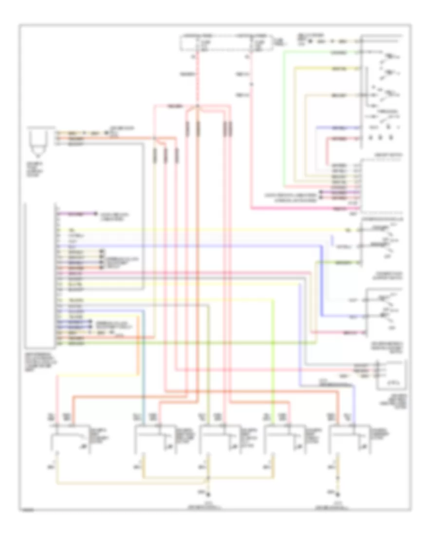
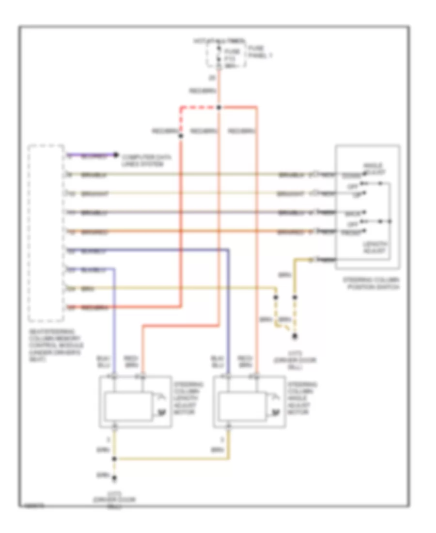
Steering Column Memory Wiring Diagram for BMW 540i 1998
 https://portal-diagnostov.com/license.html
Automotive Electricians Portal FZCO
Automotive Electricians Portal FZCO
https://portal-diagnostov.com/license.html
https://portal-diagnostov.com/license.html
Automotive Electricians Portal FZCO
Automotive Electricians Portal FZCOList of elements for Steering Column Memory Wiring Diagram for BMW 540i 1998:
- Angle adjust down
- Back
- Computer data lines system
- Front
- Fuse f13 30a
- Fuse panel 1
- Hot at all times
- Length adjust
- Nca
- Off
- Seat/steering column memory control module (under driver's seat)
- Steering column angle adjust motor
- Steering column length adjust motor
- Steering column position switch
- X173 (driver door sill)
NAVIGATION
Navigation Wiring Diagram (1 of 2) for BMW 540i 1998
 https://portal-diagnostov.com/license.html
Automotive Electricians Portal FZCO
Automotive Electricians Portal FZCO
https://portal-diagnostov.com/license.html
https://portal-diagnostov.com/license.html
Automotive Electricians Portal FZCO
Automotive Electricians Portal FZCOList of elements for Navigation Wiring Diagram (1 of 2) for BMW 540i 1998:
- (left rear of trunk)
- 30a
- Antenna amplifier
- Computer data lines systems
- Diversity
- F56
- Fuse
- Fuse panel 2
- Gps antenna
- Gps reciever
- Hot in all times
- Interior lights systems
- Light module
- Navigation control module (left side of engine compt)
- Nca
- Onboard monitor
- Red
- Sound systems
- W/ diversity
- W/o diversity
- X01008
- X10018
- X10117
- X13016
- X13016 (left rear of trunk)
- X1312
- X1313
- X18801
- X18802
- X1958
Navigation Wiring Diagram (2 of 2) for BMW 540i 1998
 https://portal-diagnostov.com/license.html
Automotive Electricians Portal FZCO
Automotive Electricians Portal FZCO
https://portal-diagnostov.com/license.html
https://portal-diagnostov.com/license.html
Automotive Electricians Portal FZCO
Automotive Electricians Portal FZCOList of elements for Navigation Wiring Diagram (2 of 2) for BMW 540i 1998:
- Computer data lines system
- Computer data lines systems
- Diversity
- F18
- F40
- Fuse
- Fuse panel 1
- Hot in run or start
- Hot w/ retained accessory power
- Instrument cluster
- Left tv amplifier
- Nca
- Radio
- Red
- Right tv amplifier
- Temperature sensor
- Video module (left rear of trunk)
- X11175
- X13016 (left rear of trunk)
- X13348
- X13349
- X18126
- X18801
- X18804
- X18805
- X18806
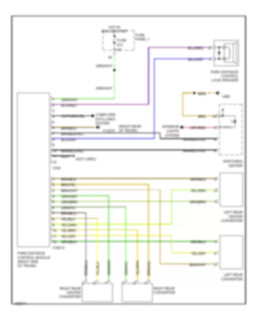
Parking Assistant Wiring Diagram for BMW 540i 1998
 https://portal-diagnostov.com/license.html
Automotive Electricians Portal FZCO
Automotive Electricians Portal FZCO
https://portal-diagnostov.com/license.html
https://portal-diagnostov.com/license.html
Automotive Electricians Portal FZCO
Automotive Electricians Portal FZCOList of elements for Parking Assistant Wiring Diagram for BMW 540i 1998:
- (not used)
- (right rear of trunk)
- Computer data lines system
- F21
- Fuse
- Fuse panel 1
- Hot in run or start
- Interior lights system
- Left rear center converter
- Left rear converter
- Nca
- Park distance control loud speaker
- Park distance control module (right side of trunk)
- Right rear center converter
- Right rear converter
- Switching center
- X13075
- X18013
- X300
- X492
POWER DISTRIBUTION
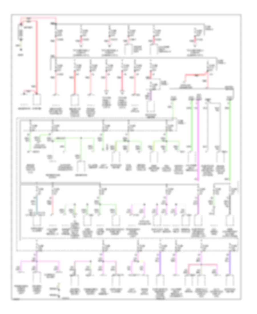
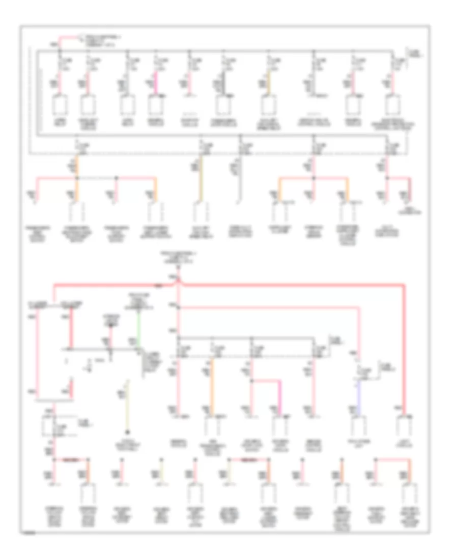
Power Distribution Wiring Diagram (1 of 3) for BMW 540i 1998
 https://portal-diagnostov.com/license.html
Automotive Electricians Portal FZCO
Automotive Electricians Portal FZCO
https://portal-diagnostov.com/license.html
https://portal-diagnostov.com/license.html
Automotive Electricians Portal FZCO
Automotive Electricians Portal FZCOList of elements for Power Distribution Wiring Diagram (1 of 3) for BMW 540i 1998:
- (w/o ike) (w/ ike)
- Abs/asc control module
- Abs/asc or abs/dsc control module
- Acc/ run/ start
- Automatic transmission range switch
- Battery
- Brake light switch
- Charging socket
- Cigar lighter relay
- Coil spring
- Coil spring (srs)
- Data link connector
- Driver's makeup mirror light
- Driver's seat belt switch
- Electrochromic rear view mirror
- Electronic driveaway protection control unit
- Electronic driveway protection control unit (ews)
- Engine control module (4.4l)
- Engine control module (dme)
- Engine control module relay
- Fuel pump relay
- Fuse 5a
- Fuse f100 200a
- Fuse f101 80a
- Fuse f102 80a
- Fuse f103 50a
- Fuse f104 50a
- Fuse f106 80a
- Fuse f107 50a
- Fuse f108 50a
- Fuse f109 80a
- Fuse f110 80a
- Fuse f111 50a
- Fuse f112 80a
- Fuse f113 80a
- Fuse f114 50a
- Fuse f14 5a
- Fuse f15 7.5a
- Fuse f16 5a
- Fuse f17 10a
- Fuse f19 5a
- Fuse f20 7.5a
- Fuse f21 5a
- Fuse f32 25a
- Fuse f34 10a
- Fuse f35 5a
- Fuse f37 5a
- Fuse f38 5a
- Fuse f39 7.5a
- Fuse f40 5a
- Fuse f41 5a
- Fuse f42 5a
- Fuse f43 5a
- Fuse f44 5a
- Fuse f45 7.5a
- Fuse panel 1
- Fuse panel 4
- Fuse panel 5
- Garage door opener
- General module
- Generator
- Heating and a/c control module
- Horn relay
- Ignition switch
- Instrument cluster
- Light module
- Multi information display (mid)
- Nca
- Oil level sensor
- Park distance control module
- Passenger's makeup mirror light
- Passenger's seat belt switch
- Rain sensor
- Rdc control module
- Rear compartment blower output stage
- Rear defogger relay
- Rear multi information display (mid)
- Red
- Run/ start
- Seat load assembly
- Secondary air injection pump relay
- Shift lock switch
- Start
- Starter
- Switching center
- Temperature switch
- To closed circuit current cutoff relay (diagram 2 of 3)
- To fuse panel 1 fuse f1 (diagram 2 of 3)
- To fuse panel 1 fuse f27 (diagram 2 of 3)
- To fuse panel 2 fuse f47 (diagram 3 of 3)
- To fuse panel 2 fuse f51 (diagram 3 of 3)
- To fuse panel 2 fuse f57 (diagram 3 of 3)
- Trailer module (ahm)
- Transmission range indicator light
- Unloader relay terminal 15
- Unloader relay terminal r (accessory)
- Unloader relay terminal15
- X1 x1
- X10
- X10012
- X10117
- X10209 red
- X1026
- X11175
- X11175 x10113
- X11238 red
- X1193
- X12
- X13030
- X18075 red
- X18090 red
- X18261 red
- X19517 red
- X27
- X300
- X332
- X60004
- X6004
- X610
- X6406
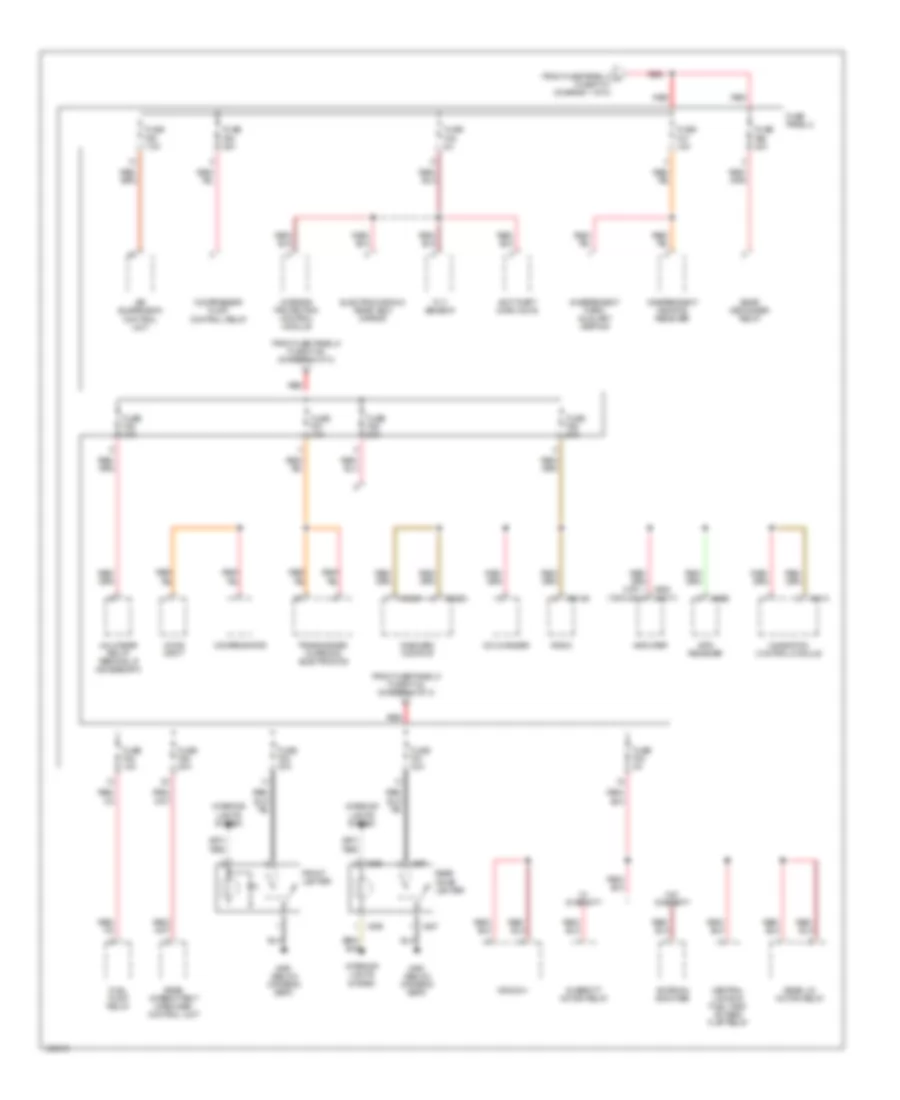
Power Distribution Wiring Diagram (2 of 3) for BMW 540i 1998
 https://portal-diagnostov.com/license.html
Automotive Electricians Portal FZCO
Automotive Electricians Portal FZCO
https://portal-diagnostov.com/license.html
https://portal-diagnostov.com/license.html
Automotive Electricians Portal FZCO
Automotive Electricians Portal FZCOList of elements for Power Distribution Wiring Diagram (2 of 3) for BMW 540i 1998:
- Abs/dsc control module
- Ags transmission control module
- Auxiliary fan high speed relay
- Auxiliary fan normal speed relay
- Closed circuit current cutoff relay
- Driver's door lock switch
- Driver's door module
- Driver's headrest motor
- Driver's seat back head recliner motor
- Driver's seat back recliner motor
- Driver's seat cushion tilt motor
- Driver's seat height motor
- Driver's seat lumbar support switch
- Driver's seat movement motor
- Driver's thigh support motor
- Electronic driveaway protection control unit (ews)
- Final stage unit
- From fuse panel 1 fuse f21 (diagram 1 of 3)
- From fuse panel 4 fuse f110 (diagram 1 of 3)
- From fuse panel 4 fuse f113 (diagram 1 of 3)
- Fuse f1 30a
- Fuse f10 30a
- Fuse f11 7.5a
- Fuse f12 5a
- Fuse f13 30a
- Fuse f2 30a
- Fuse f22 30a
- Fuse f23 7.5a
- Fuse f24 5a
- Fuse f25 7.5a
- Fuse f27 30a
- Fuse f28 15a
- Fuse f29 30a
- Fuse f3 15a
- Fuse f30 25a
- Fuse f4 20a
- Fuse f5 20a
- Fuse f6 30a
- Fuse f7 20a
- Fuse f76 40a
- Fuse f9 15a
- Fuse panel 1
- Fuse panel 6
- General module
- Headlight washer module
- Heating and a/c control module
- Horn relay
- Instrument cluster
- Integrated instrument cluster control module
- Interior lights system
- Light module
- Multi information display (mid)
- Obd ii connector
- Passenger's door module
- Passenger's seat back head adjustment switch
- Passenger's seat control switch
- Passenger's seat lumbar support switch
- Passenger's thigh support switch
- Rear multi information display (mid)
- Red
- Seat/ steering column memory control module
- Steering angle sensor
- Steering column angle adjust motor
- Steering column length adjust motor
- Sunroof module
- W/ lumbar support
- W/o lumbar support
- Wiper relay
- X10012 (right front footwell)
- X10113
- X11175
- X18341
- X254
- X332
- X38
- X70001
- X887
- X889
Power Distribution Wiring Diagram (3 of 3) for BMW 540i 1998
 https://portal-diagnostov.com/license.html
Automotive Electricians Portal FZCO
Automotive Electricians Portal FZCO
https://portal-diagnostov.com/license.html
https://portal-diagnostov.com/license.html
Automotive Electricians Portal FZCO
Automotive Electricians Portal FZCOList of elements for Power Distribution Wiring Diagram (3 of 3) for BMW 540i 1998:
- (below driver's seat)
- (hifi) (top hifi)
- Air suspension control unit
- Amplifier
- Antenna amplifier
- Anti-theft horn (dwa)
- Cd changer
- Central locking fuel tank access flap relay
- Compensator
- Compressor pump control relay
- Diversity motor relay
- Electrochromic rear view mirror
- From fuse panel 5 a fuse f101 (diagram 1 of 3)
- From fuse panel 5 fuse f102 (diagram 1 of 3)
- From fuse panel 5 fuse f106 (diagram 1 of 3)
- Front lighter
- Fuel pump relay
- Fuse f47 15a
- Fuse f48 5a
- Fuse f49 30a
- Fuse f50 7.5a
- Fuse f51 30a
- Fuse f52 30a
- Fuse f53 5a
- Fuse f54 15a
- Fuse f55 20a
- Fuse f56 30a
- Fuse f57 10a
- Fuse f58 10a
- Fuse f59 20a
- Fuse f66 40a
- Fuse panel 2
- Gps receiver
- Independent heating receiver
- Independent park/ auxiliary heating
- Interior lights system
- Interior protection control module
- Navigation control module
- Onboard monitor
- Radio
- Rear cigar lighter
- Rear defogger relay
- Rear intermittent wipe/wash control unit
- Rear lid motor relay
- Red
- Tilt sensor
- Transceiver/ charging electronics
- Unloader relay terminal r (accessory)
- Voice input
- W/ diversity
- W/o diversity
- Window
- X1313
- X18126
- X18801
- X18802
- X1958
- X386
- X387
- X490
POWER DOOR LOCKS
Power Door Locks Wiring Diagram for BMW 540i 1998
 https://portal-diagnostov.com/license.html
Automotive Electricians Portal FZCO
Automotive Electricians Portal FZCO
https://portal-diagnostov.com/license.html
https://portal-diagnostov.com/license.html
Automotive Electricians Portal FZCO
Automotive Electricians Portal FZCOList of elements for Power Door Locks Wiring Diagram for BMW 540i 1998:
- (driver door sill)
- Central locking fuel tank access flap relay
- Driver's door lock motor
- Driver's door lock switch
- Driver's door module
- Fuse f27 30a
- Fuse f29 30a
- Fuse f53 5a
- Fuse f6 30a
- Fuse panel 1
- Fuse panel 2
- General module (behind glove compartment)
- Global locking switch
- Hot at all times
- Interior lights system
- Left rear door lock motor
- Lid servo motor
- Nca
- Passenger's door lock motor
- Passenger's door module
- Rear window servo motor
- Rear window servo opening switch
- Right rear door lock motor
- Trunk lid locking switch
- Window motor relay
- X10012 (right front footwell)
- X1129
- X1131
- X173 (driver door sill)
- X253
- X254
- X332
- X492
- X494 (bottom of right c- pillar)
- X887
- X889
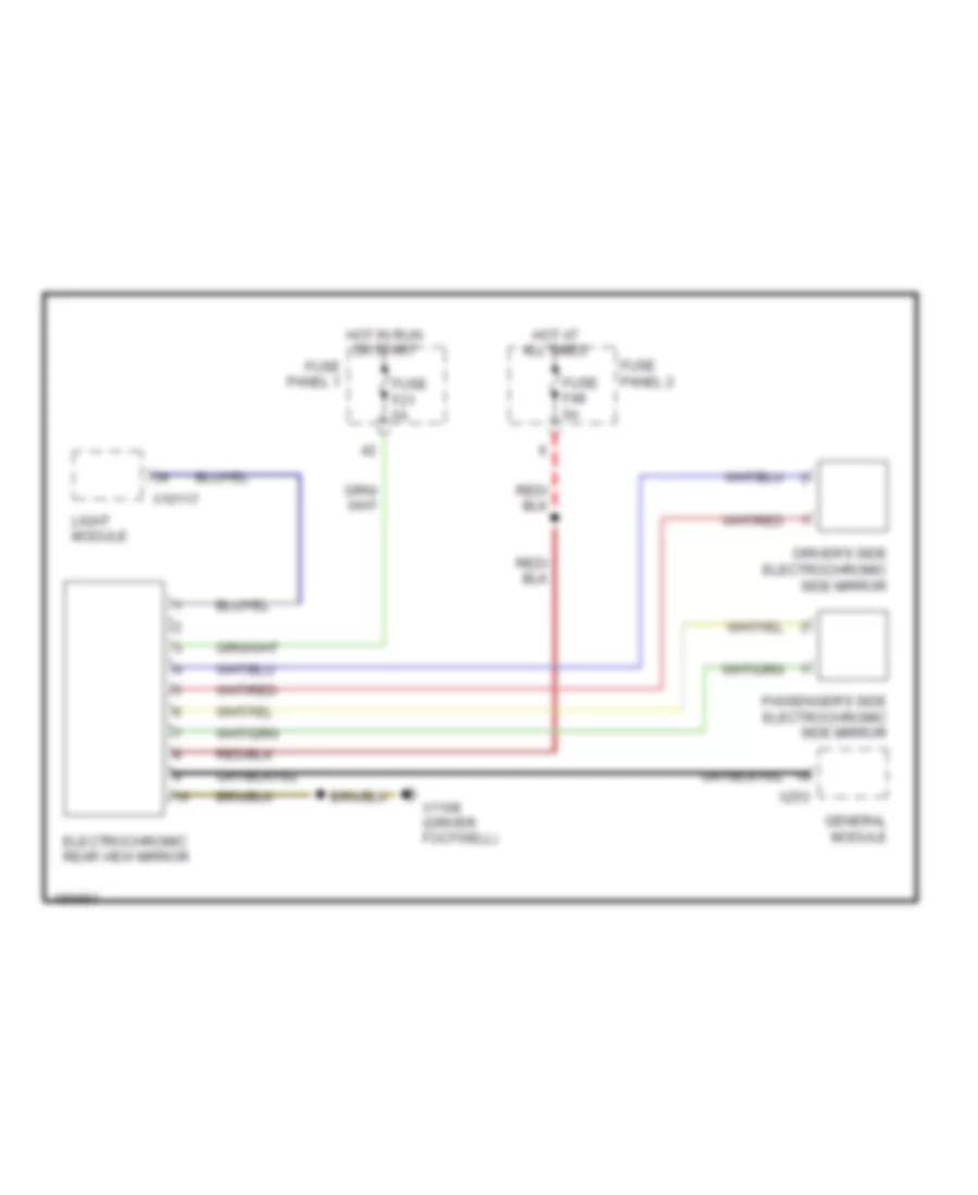
POWER MIRRORS
Electrochromic Mirror Wiring Diagram for BMW 540i 1998
 https://portal-diagnostov.com/license.html
Automotive Electricians Portal FZCO
Automotive Electricians Portal FZCO
https://portal-diagnostov.com/license.html
https://portal-diagnostov.com/license.html
Automotive Electricians Portal FZCO
Automotive Electricians Portal FZCOList of elements for Electrochromic Mirror Wiring Diagram for BMW 540i 1998:
- Driver's side electrochromic side mirror
- Electrochromic rear view mirror
- Fuse f21 5a
- Fuse f48 5a
- Fuse panel 1
- Fuse panel 2
- General module
- Hot at all times
- Hot in run or start
- Light module
- Passenger's side electrochromic side mirror
- X10117
- X1108 (driver footwell)
- X253
POWER SEATS
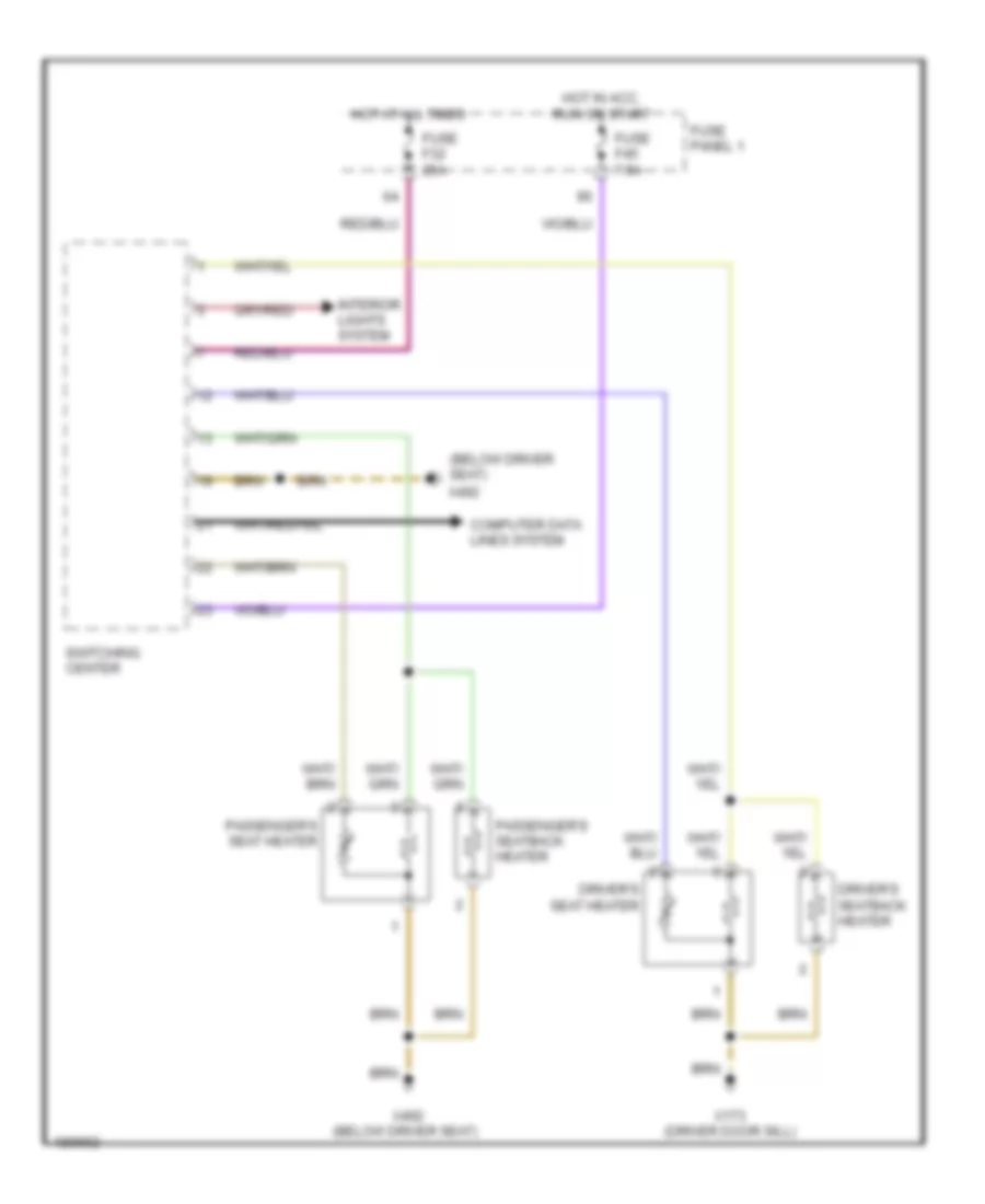
Heated Seats Wiring Diagram for BMW 540i 1998
 https://portal-diagnostov.com/license.html
Automotive Electricians Portal FZCO
Automotive Electricians Portal FZCO
https://portal-diagnostov.com/license.html
https://portal-diagnostov.com/license.html
Automotive Electricians Portal FZCO
Automotive Electricians Portal FZCOList of elements for Heated Seats Wiring Diagram for BMW 540i 1998:
- (below driver seat)
- Computer data lines system
- Driver's seat heater
- Driver's seatback heater
- Fuse f32 25a
- Fuse f45 7.5a
- Fuse panel 1
- Hot at all times
- Hot in acc, run or start
- Interior lights system
- Passenger's seat heater
- Passenger's seatback heater
- Switching center
- X173 (driver door sill)
- X492
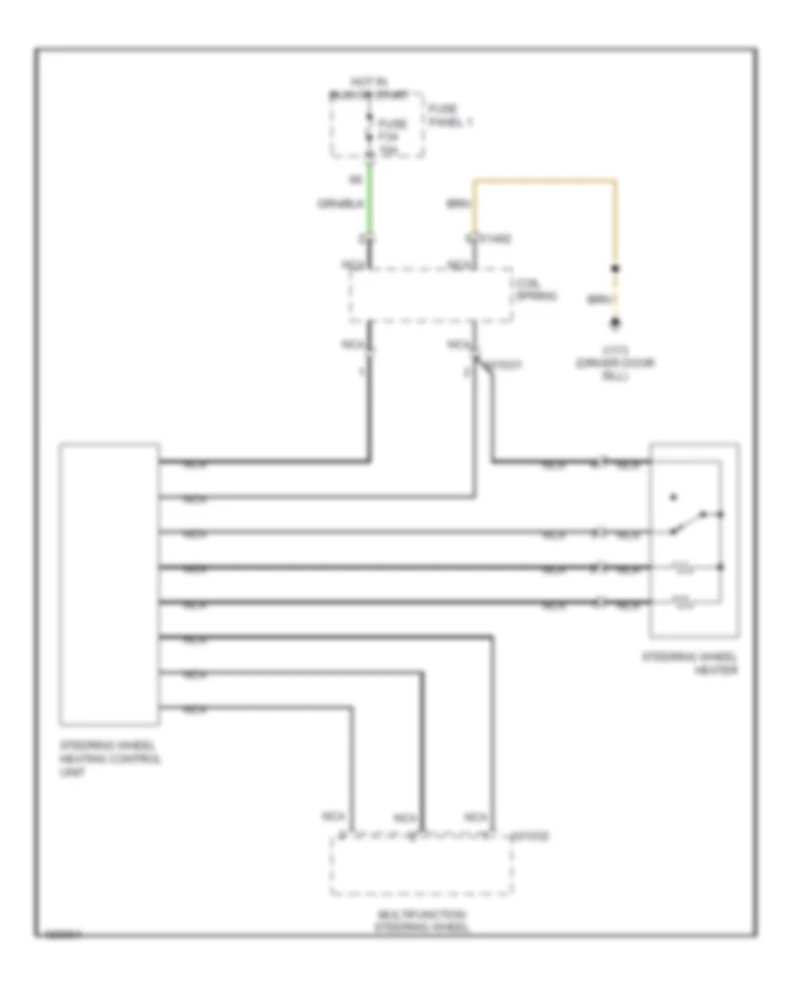
Heated Steering Wheel Wiring Diagram for BMW 540i 1998
 https://portal-diagnostov.com/license.html
Automotive Electricians Portal FZCO
Automotive Electricians Portal FZCO
https://portal-diagnostov.com/license.html
https://portal-diagnostov.com/license.html
Automotive Electricians Portal FZCO
Automotive Electricians Portal FZCOList of elements for Heated Steering Wheel Wiring Diagram for BMW 540i 1998:
- Coil spring
- Fuse f34 10a
- Fuse panel 1
- Hot in run or start
- Multifunction steering wheel
- Nca
- Steering wheel heater
- Steering wheel heating control unit
- X01031
- X01032
- X1492
- X173 (driver door sill)
Lumbar Wiring Diagram for BMW 540i 1998
 https://portal-diagnostov.com/license.html
Automotive Electricians Portal FZCO
Automotive Electricians Portal FZCO
https://portal-diagnostov.com/license.html
https://portal-diagnostov.com/license.html
Automotive Electricians Portal FZCO
Automotive Electricians Portal FZCOList of elements for Lumbar Wiring Diagram for BMW 540i 1998:
- (below driver seat)
- (driver door sill)
- Driver's seat lumbar support motor
- Driver's seat lumbar support switch
- Driver's seat lumbar support valve block
- Empty
- Fill
- Fuse f10 30a
- Fuse f13 30a
- Fuse panel 1
- Hot at all times
- Inlet valve
- Lower
- Lower chamber
- Nca
- Normal
- Outlet valve
- Passenger's seat lumbar support motor
- Passenger's seat lumbar support switch
- Passenger's seat lumbar support valve block
- Raise
- Upper chamber
- X173
- X173 (driver door sill)
- X492
- X492 (below driver seat)
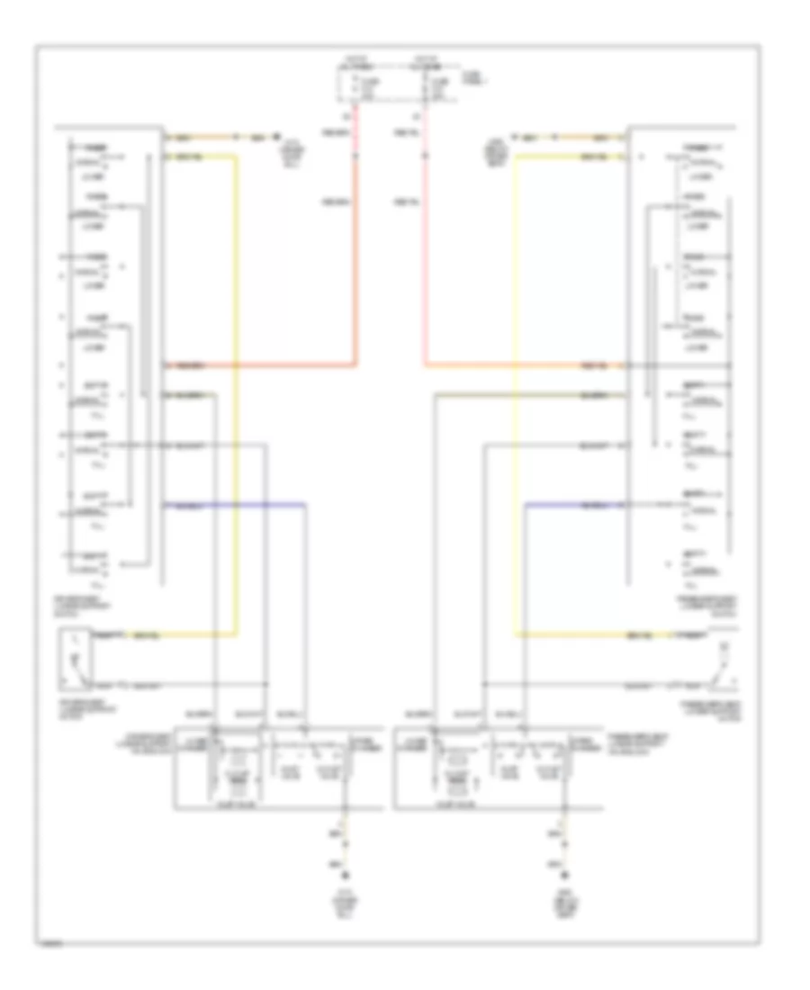
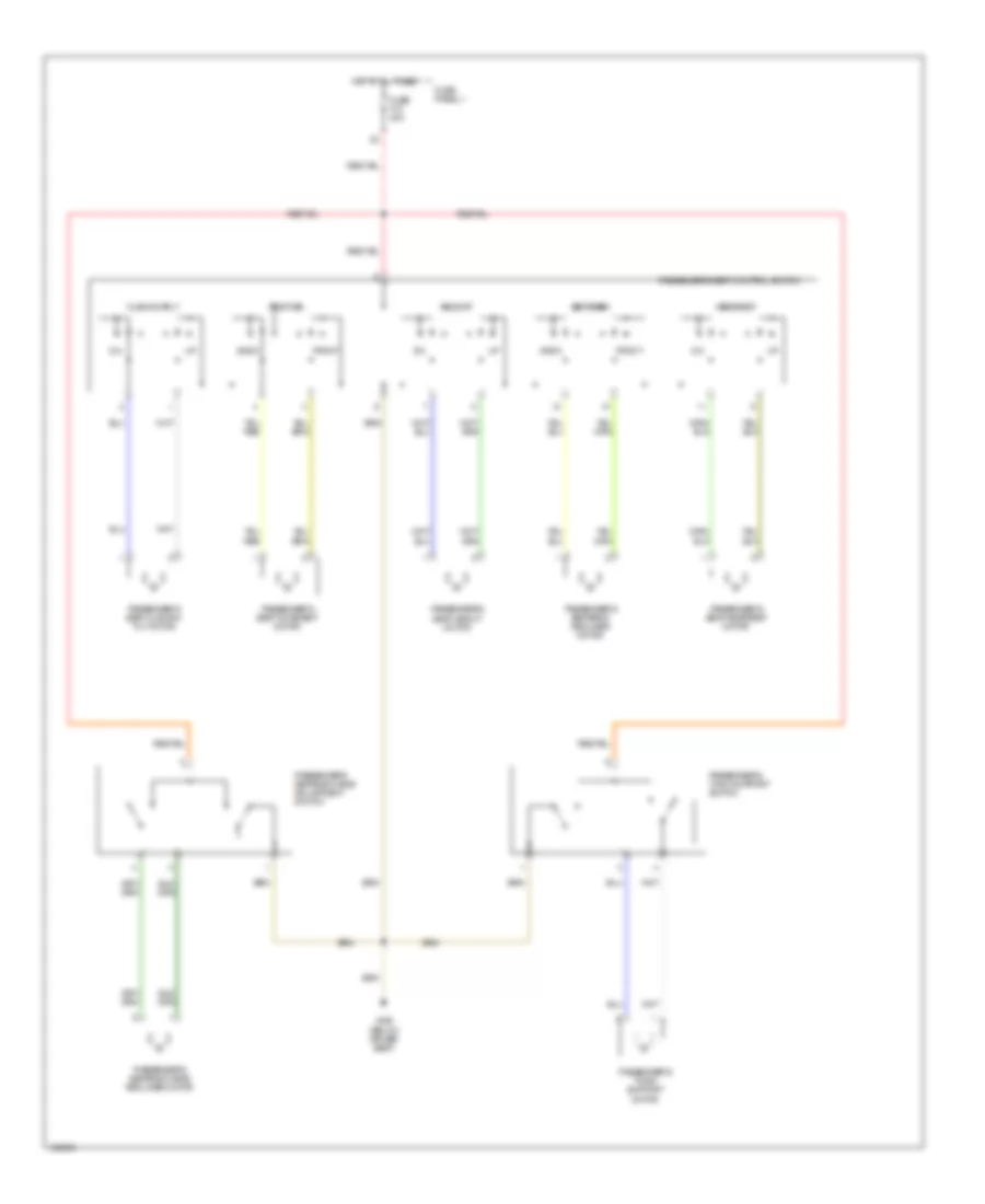
Passenger"s Power Seat Wiring Diagram for BMW 540i 1998
 https://portal-diagnostov.com/license.html
Automotive Electricians Portal FZCO
Automotive Electricians Portal FZCO
https://portal-diagnostov.com/license.html
https://portal-diagnostov.com/license.html
Automotive Electricians Portal FZCO
Automotive Electricians Portal FZCOList of elements for Passenger"s Power Seat Wiring Diagram for BMW 540i 1998:
- Back
- Cushion tilt
- Front
- Fuse f10 30a
- Fuse panel 1
- Headrest
- Height
- Hot at all times
- Passenger's seat control switch
- Passenger's seat cushion tilt motor
- Passenger's seat headrest motor
- Passenger's seat height motor
- Passenger's seat movement motor
- Passenger's seatback head adjustment switch
- Passenger's seatback head recliner motor
- Passenger's seatback recliner motor
- Passenger's thigh support motor
- Passenger's thigh support switch
- Position
- Seatback
- X492 (below driver seat)
POWER TOP/SUNROOF
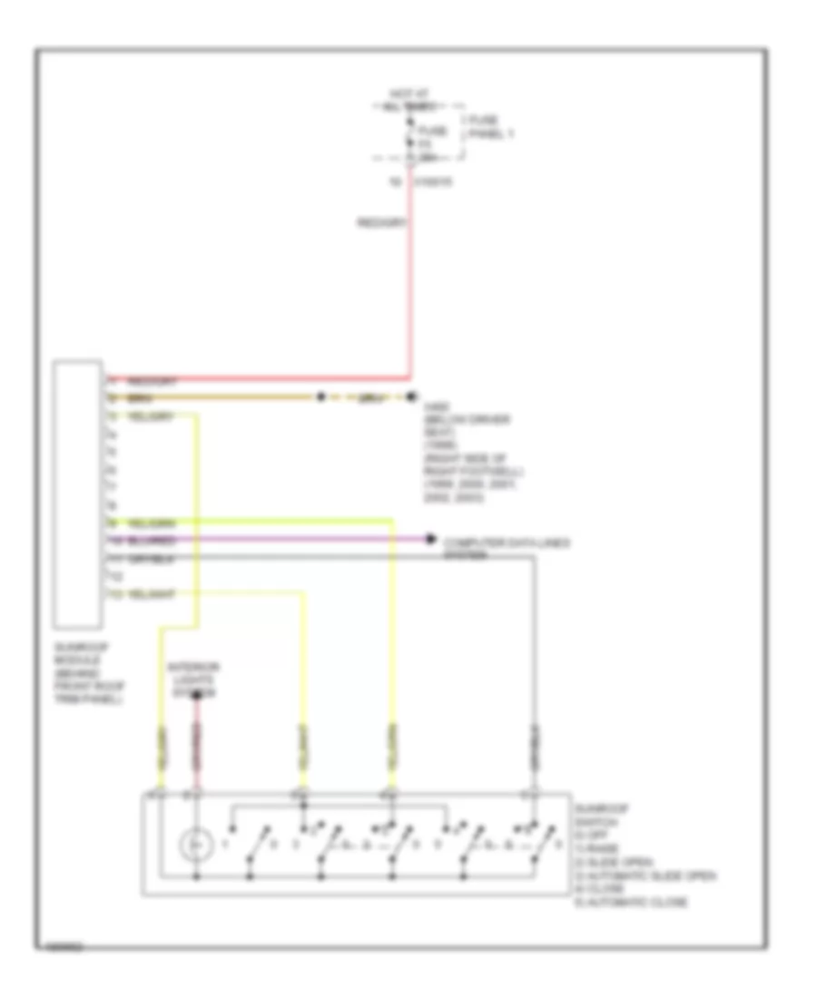
Sunroof Wiring Diagram for BMW 540i 1998
 https://portal-diagnostov.com/license.html
Automotive Electricians Portal FZCO
Automotive Electricians Portal FZCO
https://portal-diagnostov.com/license.html
https://portal-diagnostov.com/license.html
Automotive Electricians Portal FZCO
Automotive Electricians Portal FZCOList of elements for Sunroof Wiring Diagram for BMW 540i 1998:
- Computer data lines system
- Fuse f5 20a
- Fuse panel 1
- Hot at all times
- Interior lights system
- Sunroof module (behind front roof trim panel)
- Sunroof switch 0) off 1) raise 2) slide open 3) automatic slide open 4) close 5) automatic close
- X10015
- X492 (below driver seat) (1998) (right side of right footwell) (1999, 2000, 2001, 2002, 2003)
POWER WINDOWS
Power Windows Wiring Diagram (1 of 2) for BMW 540i 1998
 https://portal-diagnostov.com/license.html
Automotive Electricians Portal FZCO
Automotive Electricians Portal FZCO
https://portal-diagnostov.com/license.html
https://portal-diagnostov.com/license.html
Automotive Electricians Portal FZCO
Automotive Electricians Portal FZCOList of elements for Power Windows Wiring Diagram (1 of 2) for BMW 540i 1998:
- (below driver's seat)
- Auto close
- Auto open
- Close
- Driver's door module
- Driver's side pressure sensitive finger guard
- Driver's window motor
- Fuse f29 30a
- Fuse f6 30a
- Fuse panel 1
- Hot at all times
- Interior lights system
- Off
- Open
- Passenger's door module
- Passenger's power window switch
- Passenger's side pressure sensitive finger guard
- Passenger's window motor
- Sunroof module
- To general module (diagram 2 of 2)
- X1129
- X1131
- X151
- X151 (below driver's seat)
- X492 (below driver's seat) (1998) (right side of right footwell) (1999, 2000, 2001, 2002 2003)
- X887
- X889
Power Windows Wiring Diagram (2 of 2) for BMW 540i 1998
 https://portal-diagnostov.com/license.html
Automotive Electricians Portal FZCO
Automotive Electricians Portal FZCO
https://portal-diagnostov.com/license.html
https://portal-diagnostov.com/license.html
Automotive Electricians Portal FZCO
Automotive Electricians Portal FZCOList of elements for Power Windows Wiring Diagram (2 of 2) for BMW 540i 1998:
- (1999, 2000, 2001 2002, 2003) (right side of right footwell) (1998) (below driver seat) x490
- (below driver seat) (1998) (right side of right footwell) (1999, 2000, 2001, 2002, 2003)
- Auto close
- Auto open
- Close
- From driver's module (diagram 1 of 2)
- Fuse f11 7.5a
- Fuse f27 30a
- Fuse panel 1
- General module (behind glove compartment)
- Hot at all times
- Interior lights system
- Left rear power window switch
- Left rear window motor
- Left rear window pressure sensitive finger guard
- Off
- Open
- Open auto
- Right rear power window switch
- Right rear window motor
- Right rear window pressure sensitive finger guard
- X173 (driver door sill) (1998) (below driver's seat) (1999, 2000, 2001, 2002, 2003)
- X253
- X254
- X332
- X492
- X492 (below driver seat) (1998) (right side of right footwell) (1999, 2000, 2001, 2002, 2003)
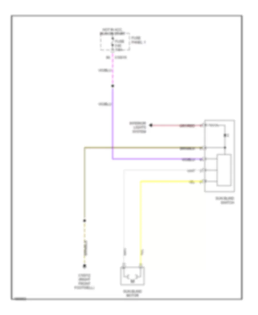
Rear Window Sun Shade Wiring Diagram for BMW 540i 1998
 https://portal-diagnostov.com/license.html
Automotive Electricians Portal FZCO
Automotive Electricians Portal FZCO
https://portal-diagnostov.com/license.html
https://portal-diagnostov.com/license.html
Automotive Electricians Portal FZCO
Automotive Electricians Portal FZCOList of elements for Rear Window Sun Shade Wiring Diagram for BMW 540i 1998:
- Fuse f45 7.5a
- Fuse panel 1
- Hot in acc, run or start
- Interior lights system
- Sun blind motor
- Sun blind switch
- X10012 (right front footwell)
- X10015
RADIO
Radio Wiring Diagram (1 of 3) for BMW 540i 1998
 https://portal-diagnostov.com/license.html
Automotive Electricians Portal FZCO
Automotive Electricians Portal FZCO
https://portal-diagnostov.com/license.html
https://portal-diagnostov.com/license.html
Automotive Electricians Portal FZCO
Automotive Electricians Portal FZCOList of elements for Radio Wiring Diagram (1 of 3) for BMW 540i 1998:
- Amplifier (left side of engine compt)
- Fuse f56 30a
- Fuse panel 2
- Hifi
- Hot at all times
- Left front high range speaker
- Left front mid range speaker
- Left front speaker
- Left medium/high range speaker
- Left rear speaker
- Navigation system
- Right front high range speaker
- Right front mid range speaker
- Right front speaker
- Right medium/high range speaker
- Right rear speaker
- Sedan
- Ses language input system
- Stereo/hifi
- Subwoofer speaker
- Top hifi
- Wagon
- X1260
- X1261
- X13016 (left rear of trunk)
- X18184
- X18189
- X18771
- X18772
- X18773
- X605
- X606
- X761
- X763
Radio Wiring Diagram (2 of 3) for BMW 540i 1998
 https://portal-diagnostov.com/license.html
Automotive Electricians Portal FZCO
Automotive Electricians Portal FZCO
https://portal-diagnostov.com/license.html
https://portal-diagnostov.com/license.html
Automotive Electricians Portal FZCO
Automotive Electricians Portal FZCOList of elements for Radio Wiring Diagram (2 of 3) for BMW 540i 1998:
- Coil spring
- Diversity
- Engine control module (dme)
- Eur
- Fm amplifier, lockout circuit
- Fm1
- Fm2
- Fuse f43 5a
- Fuse f44 5a
- Fuse f53 5a
- Fuse f58 10a
- Fuse panel 1
- Fuse panel 2
- General module
- Hot at all times
- Hot in acc, run or start
- Independent heating receiver
- Navigation system
- Nca
- Onboard monitor
- Rear window
- Right tv amplifier
- Transceiver/ charging electronics
- Unloader relay terminal r (right side of trunk)
- Usa
- Video module
- Voice input
- X01026
- X01027
- X01034
- X01119
- X01125
- X1108 (driver footwell)
- X1143
- X13016 (left rear of trunk)
- X13344
- X332
- X380
- X424
- X498
- X60004
Radio Wiring Diagram (3 of 3) for BMW 540i 1998
 https://portal-diagnostov.com/license.html
Automotive Electricians Portal FZCO
Automotive Electricians Portal FZCO
https://portal-diagnostov.com/license.html
https://portal-diagnostov.com/license.html
Automotive Electricians Portal FZCO
Automotive Electricians Portal FZCOList of elements for Radio Wiring Diagram (3 of 3) for BMW 540i 1998:
- (left rear of trunk)
- Antenna amplifier
- Cd changer
- Computer data lines system
- Ibus
- Instrument cluster (w/o ike)
- Integrated instrument cluster control module (w/o ike)
- Interface
- Interior lights system
- Left side steering wheel electronics
- Multifunction steering wheel
- Navigation control module
- Navigation system
- Nca
- Radio
- Red
- Right side steering wheel electronics
- W/ diversity
- W/o diversity
- X01008
- X01012
- X01028
- X01029
- X01030
- X01037
- X01038
- X10113
- X11176
- X13016
- X1312
- X1313
- X13342
- X18126
- X18180
- X18805
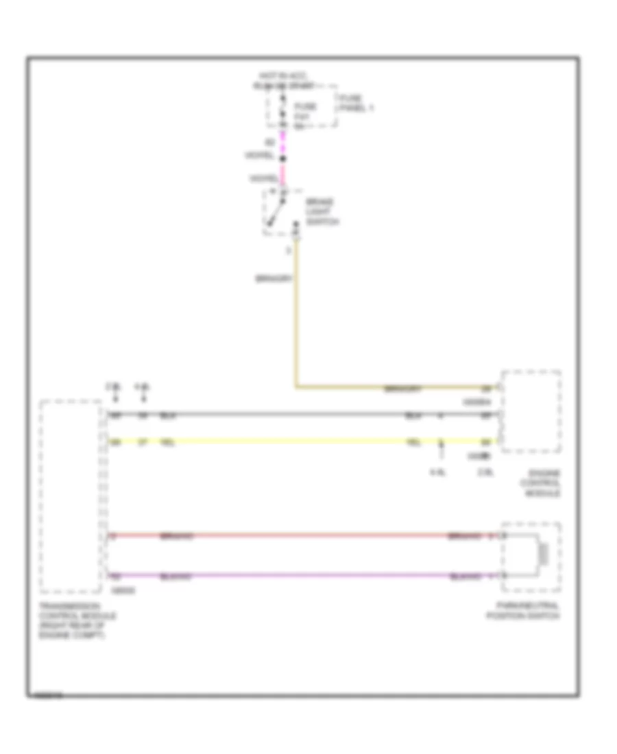
SHIFT INTERLOCK
Shift Interlock Wiring Diagram for BMW 540i 1998
 https://portal-diagnostov.com/license.html
Automotive Electricians Portal FZCO
Automotive Electricians Portal FZCO
https://portal-diagnostov.com/license.html
https://portal-diagnostov.com/license.html
Automotive Electricians Portal FZCO
Automotive Electricians Portal FZCOList of elements for Shift Interlock Wiring Diagram for BMW 540i 1998:
- 2.8l
- 4.4l
- Brake light switch
- Engine control module
- Fuse f41 5a
- Fuse panel 1
- Hot in acc, run or start
- Park/neutral position switch
- Transmission control module (right rear of engine compt)
- X6000
- X60004
- X8600
STARTING/CHARGING
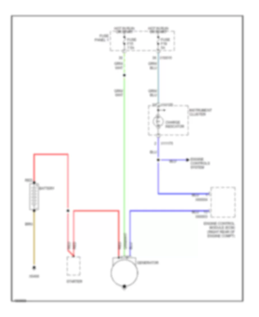
Charging Wiring Diagram for BMW 540i 1998
 https://portal-diagnostov.com/license.html
Automotive Electricians Portal FZCO
Automotive Electricians Portal FZCO
https://portal-diagnostov.com/license.html
https://portal-diagnostov.com/license.html
Automotive Electricians Portal FZCO
Automotive Electricians Portal FZCOList of elements for Charging Wiring Diagram for BMW 540i 1998:
- Battery
- Charge indicator
- Engine control module (ecm) (right rear of engine compt)
- Engine controls system
- Fuse f15 7.5a
- Fuse f18 5a
- Fuse panel 1
- Generator
- Hot in run or start
- Instrument cluster
- Red
- Starter
- X10015
- X11175
- X60003
- X60004
- X6406
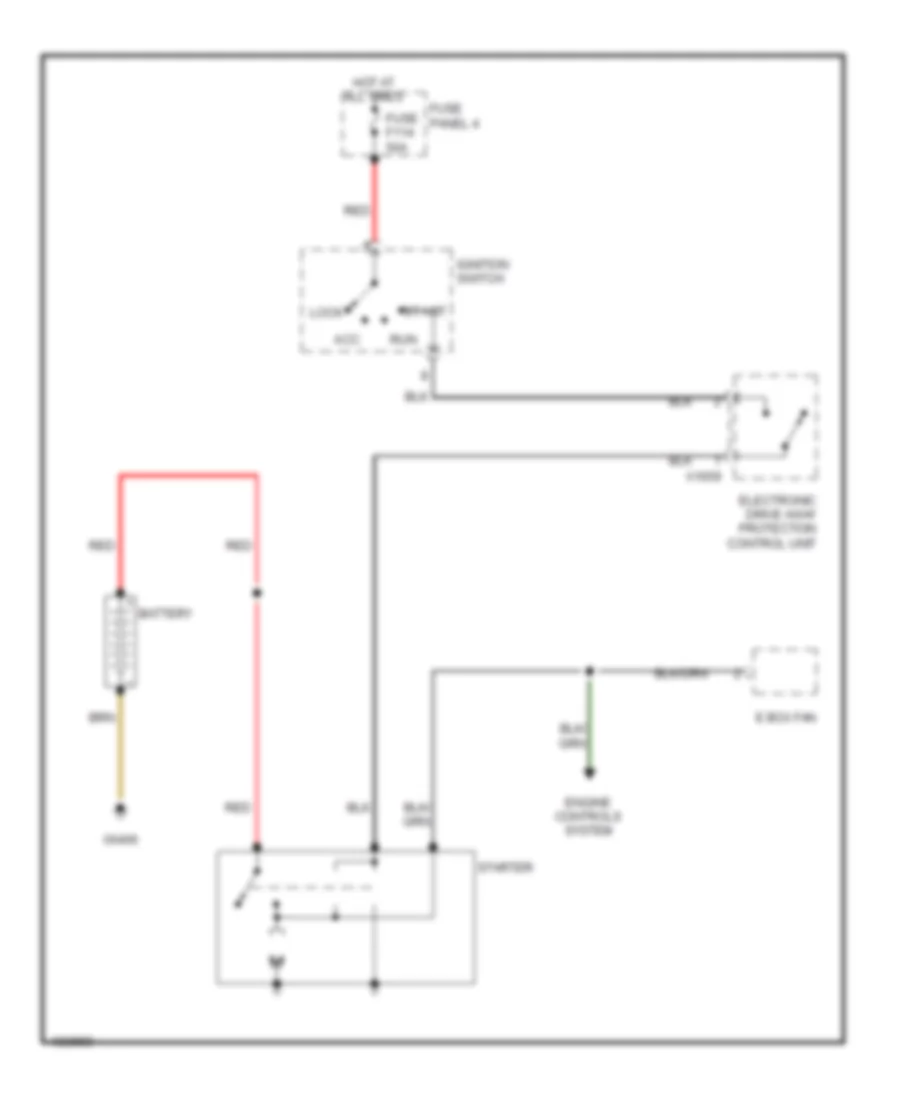
Starting Wiring Diagram for BMW 540i 1998
 https://portal-diagnostov.com/license.html
Automotive Electricians Portal FZCO
Automotive Electricians Portal FZCO
https://portal-diagnostov.com/license.html
https://portal-diagnostov.com/license.html
Automotive Electricians Portal FZCO
Automotive Electricians Portal FZCOList of elements for Starting Wiring Diagram for BMW 540i 1998:
- Acc
- Battery
- E box fan
- Electronic drive away protection control unit
- Engine controls system
- Fuse f114 50a
- Fuse panel 4
- Hot at all times
- Ignition switch
- Lock
- Red
- Run
- Start
- Starter
- X1659
- X6406
SUPPLEMENTAL RESTRAINTS
Supplemental Restraints Wiring Diagram (1 of 2) for BMW 540i 1998
 https://portal-diagnostov.com/license.html
Automotive Electricians Portal FZCO
Automotive Electricians Portal FZCO
https://portal-diagnostov.com/license.html
https://portal-diagnostov.com/license.html
Automotive Electricians Portal FZCO
Automotive Electricians Portal FZCOList of elements for Supplemental Restraints Wiring Diagram (1 of 2) for BMW 540i 1998:
- Air bag ind
- Battery safety terminal generator
- Computer data lines system
- Driver air bag head area generator
- Driver's seat belt tension generator
- Fuse f40 5a
- Fuse f42 5a
- Fuse panel 1
- General module
- Hot in acc, run or start
- Instrument cluster
- Left rear head area air bag inflator assembly (2000, 2001, 2002, 2003)
- Nca
- Passenger air bag head area generator
- Passenger's seat belt tension generator
- Red
- Right rear door side air bag generator
- Right rear head area air bag inflator assembly (2000, 2001, 2002, 2003)
- W/ ike
- W/o ike
- X10113
- X1081
- X11175
- X11176
- X16
- X253
- X46 (rear center console)
Supplemental Restraints Wiring Diagram (2 of 2) for BMW 540i 1998
 https://portal-diagnostov.com/license.html
Automotive Electricians Portal FZCO
Automotive Electricians Portal FZCO
https://portal-diagnostov.com/license.html
https://portal-diagnostov.com/license.html
Automotive Electricians Portal FZCO
Automotive Electricians Portal FZCOList of elements for Supplemental Restraints Wiring Diagram (2 of 2) for BMW 540i 1998:
- Air bag contact plate
- Coil spring
- Driver's air bag gas generator
- Driver's door for side air bag inflator assembly
- Driver's seat belt switch
- Left front sensor (air bag)
- Left rear door side air bag generator
- Nca
- Passenger's air bag gas generator
- Passenger's door for side air bag inflator assembly
- Passenger's seat belt switch
- Red
- Right front sensor (air bag)
- Seat load assembly
- X01009
- X10012 (right side of right footwell)
- X10170
- X10218
- X46 (rear center console)
TRANSMISSION
Transmission Wiring Diagram (1 of 2) for BMW 540i 1998
 https://portal-diagnostov.com/license.html
Automotive Electricians Portal FZCO
Automotive Electricians Portal FZCO
https://portal-diagnostov.com/license.html
https://portal-diagnostov.com/license.html
Automotive Electricians Portal FZCO
Automotive Electricians Portal FZCOList of elements for Transmission Wiring Diagram (1 of 2) for BMW 540i 1998:
- Ags transmission control module (right rear side of engine compt, in e box)
- Down shift
- Engine electronics fuse carrier (right rear side of engine compt in e box)
- Fuse 7.5a
- Fuse box
- Fuse f1 30a
- Fuse f38 5a
- Fuse f4 30a
- Gear indicator light
- General module
- Hot at all times
- Hot in accy, run & start
- Hot in run & start
- Hot with engine relay energized
- Kick down switch (driver's side footwell)
- Light module (right side of right footwell)
- Manual gearshift
- Off
- Park/neutral position switch (center cosole)
- Red
- Selector lever position switch (center console)
- Steptronic switch (center console)
- Up shift
- X10012 (right side of right footwell under carpet)
- X10015
- X1193
- X1599
- X1600
- X254
- X38
- X6453 (right rear side of engine compt)
- X70001
- X70003
- X8582
Transmission Wiring Diagram (2 of 2) for BMW 540i 1998
 https://portal-diagnostov.com/license.html
Automotive Electricians Portal FZCO
Automotive Electricians Portal FZCO
https://portal-diagnostov.com/license.html
https://portal-diagnostov.com/license.html
Automotive Electricians Portal FZCO
Automotive Electricians Portal FZCOList of elements for Transmission Wiring Diagram (2 of 2) for BMW 540i 1998:
- Ags transmission control module (right rear side of engine compt, in e box)
- Automatic transmission range switch (right side of transmission)
- Automatic transmission range switch 0 off 1 on
- Can-high
- Can-low
- Computer data lines system
- Engine control module (dme) (right rear of engine compt in e box)
- Nca
- Oil temperature sensor
- Output shaft speed sensor
- Pnk
- Pressure regulator 1
- Pressure regulator 2
- Pressure regulator 3
- Pressure regulator 4
- Pressure regulator 5
- Red
- Solenoid valve 1
- Solenoid valve 2
- Solenoid valve 3
- Transmission control unit (on left side of transmission)
- Turbine shaft speed sensor
- X6002
- X6004
- X70004
- X8505
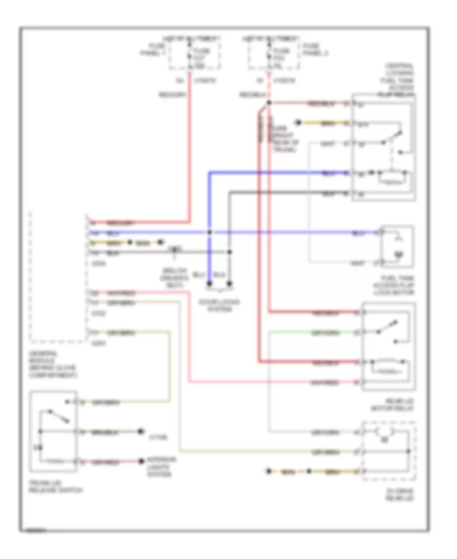
TRUNK, TAILGATE, FUEL DOOR
Trunk & Fuel Door Release Wiring Diagram for BMW 540i 1998
 https://portal-diagnostov.com/license.html
Automotive Electricians Portal FZCO
Automotive Electricians Portal FZCO
https://portal-diagnostov.com/license.html
https://portal-diagnostov.com/license.html
Automotive Electricians Portal FZCO
Automotive Electricians Portal FZCOList of elements for Trunk & Fuel Door Release Wiring Diagram for BMW 540i 1998:
- (below driver's seat)
- 87a
- Central locking fuel tank access flap relay
- Door locks system
- Fuel tank access flap lock motor
- Fuse f27 30a
- Fuse f53 5a
- Fuse panel 1
- Fuse panel 2
- General module (behind glove compartment)
- Hot at all times
- Interior lights system
- Rear lid motor relay
- Trunk lid release switch
- X10015
- X10016
- X1108
- X253
- X254
- X332
- X492
- X498 (right rear of trunk)
- Zv drive rear lid
WARNING SYSTEMS
Chime Wiring Diagram for BMW 540i 1998
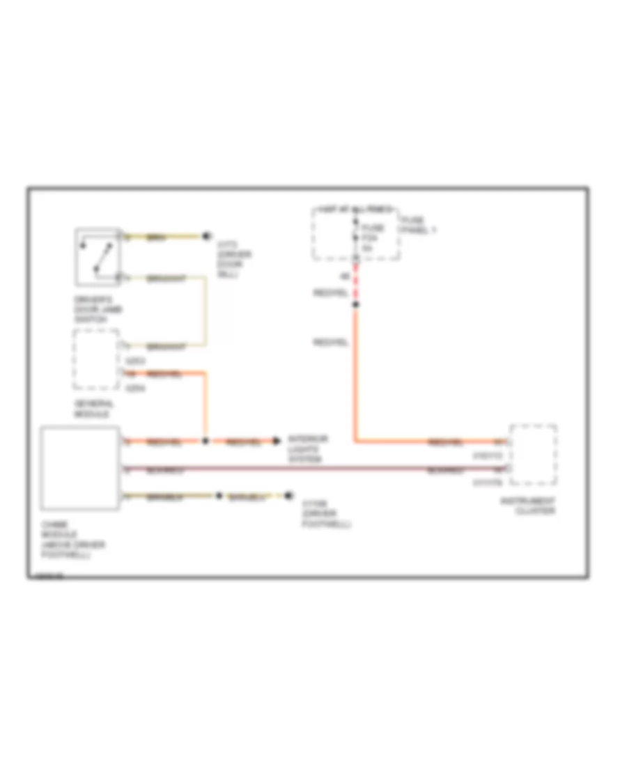 https://portal-diagnostov.com/license.html
Automotive Electricians Portal FZCO
Automotive Electricians Portal FZCO
https://portal-diagnostov.com/license.html
https://portal-diagnostov.com/license.html
Automotive Electricians Portal FZCO
Automotive Electricians Portal FZCOList of elements for Chime Wiring Diagram for BMW 540i 1998:
- Chime module (above driver footwell)
- Driver's door jamb switch
- Fuse f24 5a
- Fuse panel 1
- General module
- Hot at all times
- Instrument cluster
- Interior lights system
- X10113
- X1108 (driver footwell)
- X11176
- X173 (driver door sill)
- X253
- X254
Tire Pressure Monitoring Wiring Diagram for BMW 540i 1998
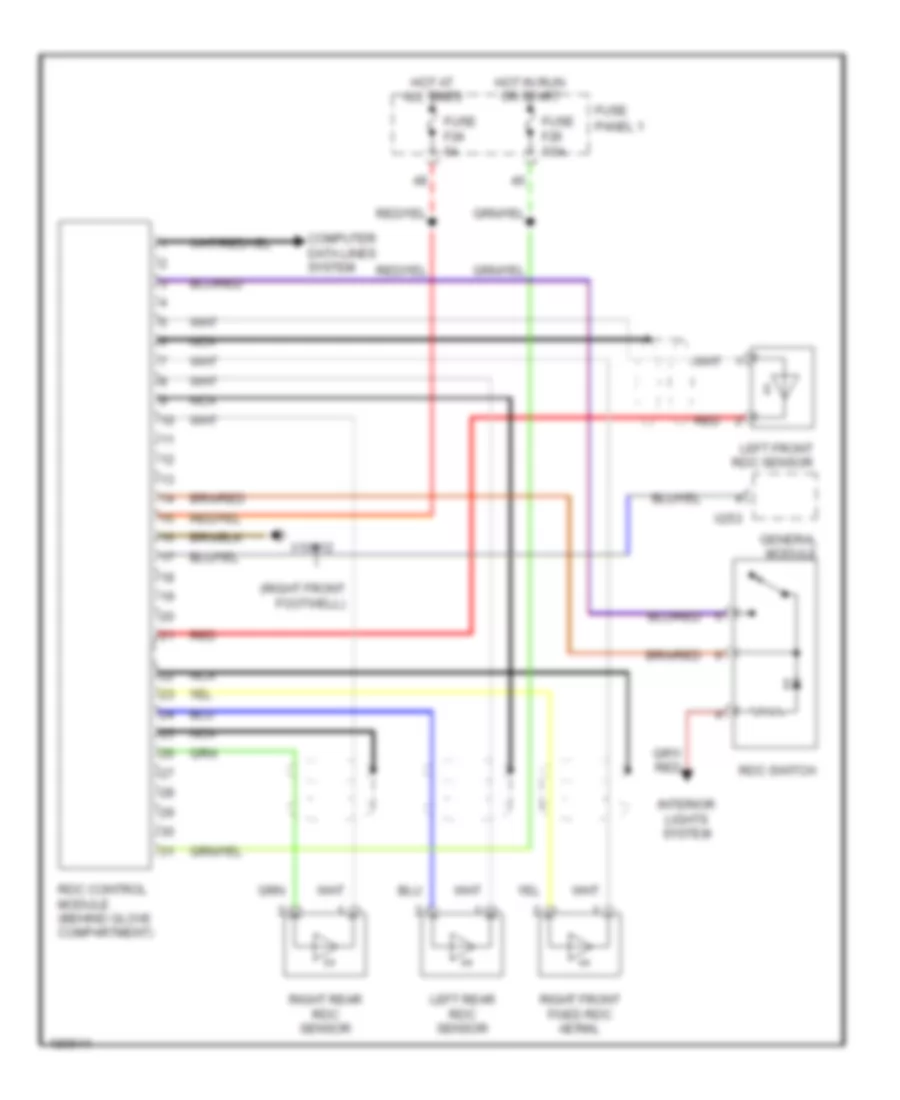 https://portal-diagnostov.com/license.html
Automotive Electricians Portal FZCO
Automotive Electricians Portal FZCO
https://portal-diagnostov.com/license.html
https://portal-diagnostov.com/license.html
Automotive Electricians Portal FZCO
Automotive Electricians Portal FZCOList of elements for Tire Pressure Monitoring Wiring Diagram for BMW 540i 1998:
- (right front footwell)
- Computer data lines system
- Fuse f20 7.5a
- Fuse f24 5a
- Fuse panel 1
- General module
- Hot at all times
- Hot in run or start
- Interior lights system
- Left front rdc sensor
- Left rear rdc sensor
- Nca
- Rdc control module (behind glove compartment)
- Rdc switch
- Red
- Right front fixed rdc aerial
- Right rear rdc sensor
- X10012
- X253
WIPER/WASHER
Headlamp Washer Wiring Diagram for BMW 540i 1998
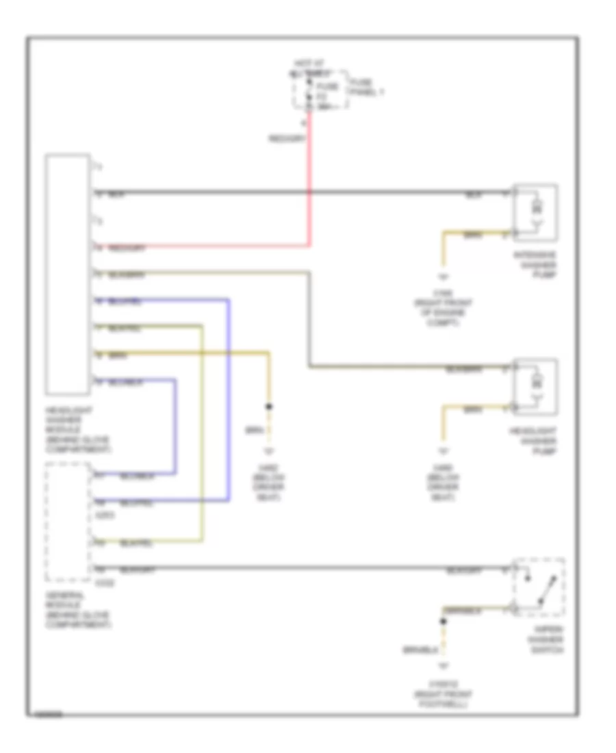 https://portal-diagnostov.com/license.html
Automotive Electricians Portal FZCO
Automotive Electricians Portal FZCO
https://portal-diagnostov.com/license.html
https://portal-diagnostov.com/license.html
Automotive Electricians Portal FZCO
Automotive Electricians Portal FZCOList of elements for Headlamp Washer Wiring Diagram for BMW 540i 1998:
- Fuse f2 30a
- Fuse panel 1
- General module (behind glove compartment)
- Headlight washer module (behind glove compartment)
- Headlight washer pump
- Hot at all times
- Intensive washer pump
- Wiper/ washer switch
- X10012 (right front footwell)
- X166 (right front of engine compt)
- X253
- X332
- X490 (below driver seat)
- X492 (below driver seat)
Washer Jet Heater Wiring Diagram for BMW 540i 1998
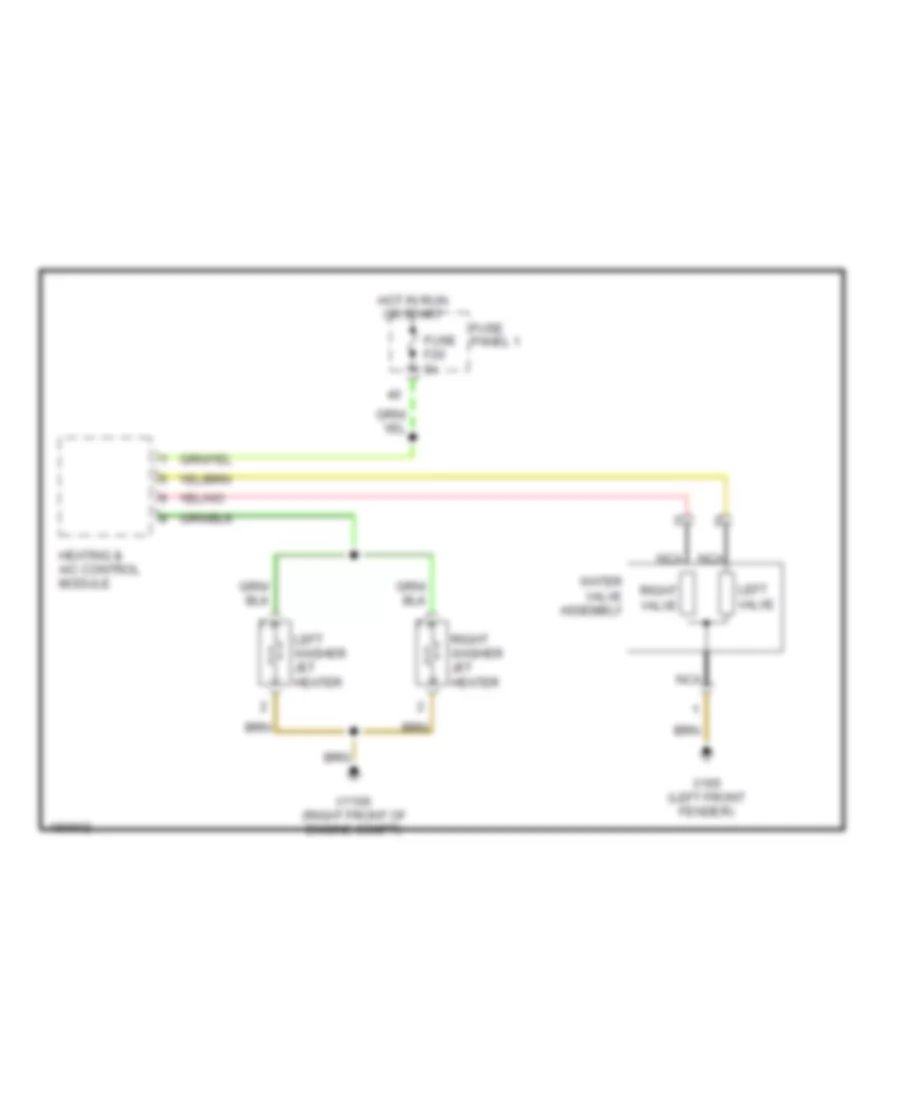 https://portal-diagnostov.com/license.html
Automotive Electricians Portal FZCO
Automotive Electricians Portal FZCO
https://portal-diagnostov.com/license.html
https://portal-diagnostov.com/license.html
Automotive Electricians Portal FZCO
Automotive Electricians Portal FZCOList of elements for Washer Jet Heater Wiring Diagram for BMW 540i 1998:
- Fuse f20 5a
- Fuse panel 1
- Heating & a/c control module
- Hot in run or start
- Left valve
- Left washer jet heater
- Nca
- Right valve
- Right washer jet heater
- Water valve assembly
- X1106 (right front of engine compt)
- X165 (left front fender)
Wiper/Washer Wiring Diagram for BMW 540i 1998
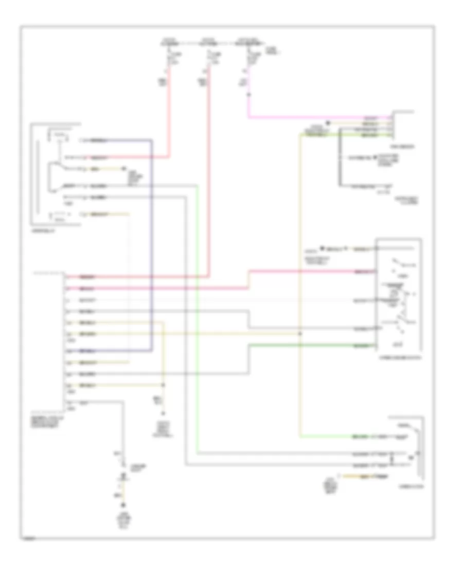 https://portal-diagnostov.com/license.html
Automotive Electricians Portal FZCO
Automotive Electricians Portal FZCO
https://portal-diagnostov.com/license.html
https://portal-diagnostov.com/license.html
Automotive Electricians Portal FZCO
Automotive Electricians Portal FZCOList of elements for Wiper/Washer Wiring Diagram for BMW 540i 1998:
- (right front footwell)
- Computer data lines system
- Fast
- Fuse f1 30a
- Fuse f11 7.5a
- Fuse f38 5a
- Fuse panel 1
- General module (behind glove compartment)
- Hot at all times
- Hot in acc, run or start
- Instrument cluster
- Int
- Nca
- Normal
- Off
- Park
- Rain sensor
- Run
- Single
- Slow
- Wash
- Washer pump
- Wiper motor
- Wiper relay
- Wiper/washer switch
- X10012
- X10012 (right front footwell)
- X11176
- X151 (below driver seat)
- X253
- X254
- X332
- X490 (driver door sill)

 Čeština
 Dansk
Dansk Deutsch
 Ελληνικά
 English
 English
 Español
 Suomi
Suomi Français
 Français
 עברית
עברית Hrvatski
 Magyar
 Italiano
 日本語
日本語 Nederlands
 Polski
 Português
 Português
 Română
 Русский
 Slovenčina
 Slovenščina
 Svenska
 Türkçe
 中文 (中国)
