AIR CONDITIONING
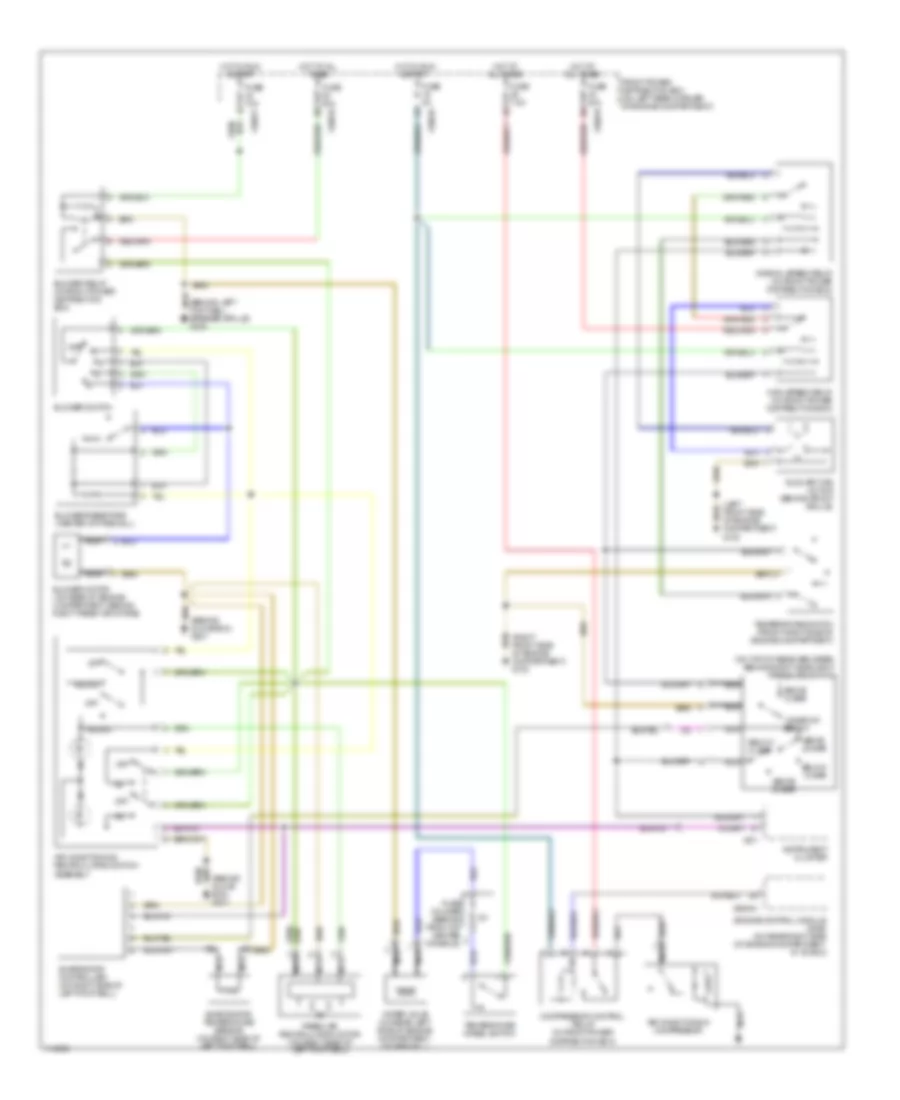
2.5L
2.5L, Manual A/C Wiring Diagram for BMW M Roadster 2000
 https://portal-diagnostov.com/license.html
Automotive Electricians Portal FZCO
Automotive Electricians Portal FZCO
https://portal-diagnostov.com/license.html
https://portal-diagnostov.com/license.html
Automotive Electricians Portal FZCO
Automotive Electricians Portal FZCO
List of elements for 2.5L, Manual A/C Wiring Diagram for BMW M Roadster 2000:
- & start
- (behind glove box) g201
- (behind left footwell speaker grille) g200
- (left front side of engine compartment) g100
- (on top of receiver-drier, behind right headlight) pressure switch
- (right front side of engine compartment) g103
- 15 bar or below
- A/c
- Above 18 bar
- Above 2.6 bar
- Above 30 bar
- Air conditioning compressor
- Air conditioning/ recirculating switch assembly
- All times
- Auxiliary fan motor (behind front grille)
- Below 1.5 bar
- Below 21 bar
- Blower motor (on rear of engine compartment, behind right fresh air intake)
- Blower relay (in front power distribution box)
- Blower resistors (center of firewall)
- Blower switch
- Compressor control relay (in front power distribution box)
- Engine control module (dme) (on rear right side of engine compartment, in "e" box)
- Evaporator controller (on right side of left footwell)
- Evaporator temperature sensor (on right side of left footwell)
- Fresh air recirculation motor (on right side of left footwell)
- Front power distribution box (on left rear corner of engine compartment)
- Fuse 10a
- Fuse 30a
- Fuse 5a
- Fuse 7.5a
- Fuse holder (behind front of center console)
- High speed relay (in front power distribution box)
- Hot at
- Hot at all times
- Hot in run
- Hot in run & start
- Instrument cluster
- Nca
- Normal speed relay (in front power distribution box)
- Off
- Recirc
- Temperature switch (front right side of engine compartment)
- Temperature wheel switch
- Water valve (on rear left side of engine compartment, on firewall)
- X10016
- X10017
- X10018
- X271
- X60004
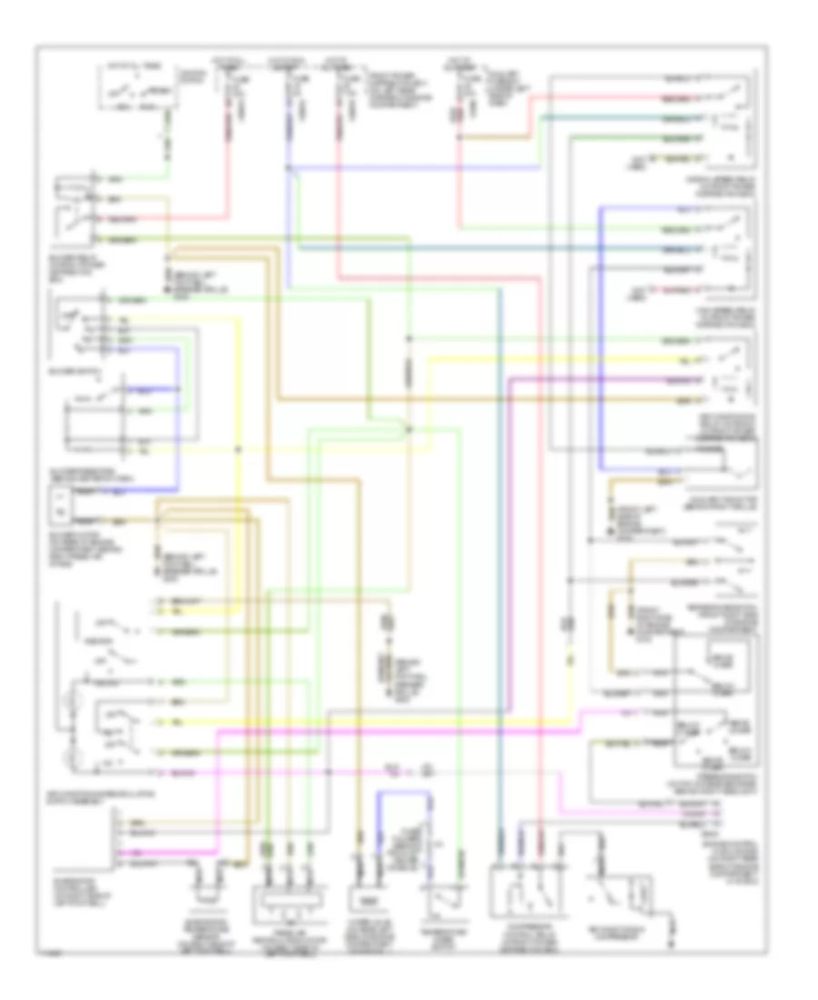
2.8L
2.8L, Manual A/C Wiring Diagram for BMW M Roadster 2000
 https://portal-diagnostov.com/license.html
Automotive Electricians Portal FZCO
Automotive Electricians Portal FZCO
https://portal-diagnostov.com/license.html
https://portal-diagnostov.com/license.html
Automotive Electricians Portal FZCO
Automotive Electricians Portal FZCOList of elements for 2.8L, Manual A/C Wiring Diagram for BMW M Roadster 2000:
- & start
- (behind glove box) g201
- (behind left footwell speaker grille) g200
- (left front side of engine compartment) g100
- (on top of receiver-drier, behind right headlight) pressure switch
- (right front side of engine compartment) g103
- 15 bar or below
- A/c
- Above 18 bar
- Above 2.6 bar
- Above 30 bar
- Air conditioning compressor
- Air conditioning/ recirculating switch assembly
- All times
- Auxiliary fan motor (behind front grille)
- Below 1.5 bar
- Below 21 bar
- Blower motor (on rear of engine compartment, behind right fresh air intake)
- Blower relay (in front power distribution box)
- Blower resistors (center of firewall)
- Blower switch
- Compressor control relay (in front power distribution box)
- Engine control module (dme) (on rear right side of engine compartment, in "e" box)
- Evaporator controller (on right side of left footwell)
- Evaporator temperature sensor (on right side of left footwell)
- Fresh air recirculation motor (on right side of left footwell)
- Front power distribution box (on left rear corner of engine compartment)
- Fuse 10a
- Fuse 30a
- Fuse 5a
- Fuse 7.5a
- Fuse holder (behind front of center console)
- High speed relay (in front power distribution box)
- Hot at
- Hot at all times
- Hot in run
- Hot in run & start
- Instrument cluster
- Nca
- Normal speed relay (in front power distribution box)
- Off
- Recirc
- Temperature switch (front right side of engine compartment)
- Temperature wheel switch
- Water valve (on rear left side of engine compartment, on firewall)
- X10016
- X10017
- X10018
- X271
- X60004
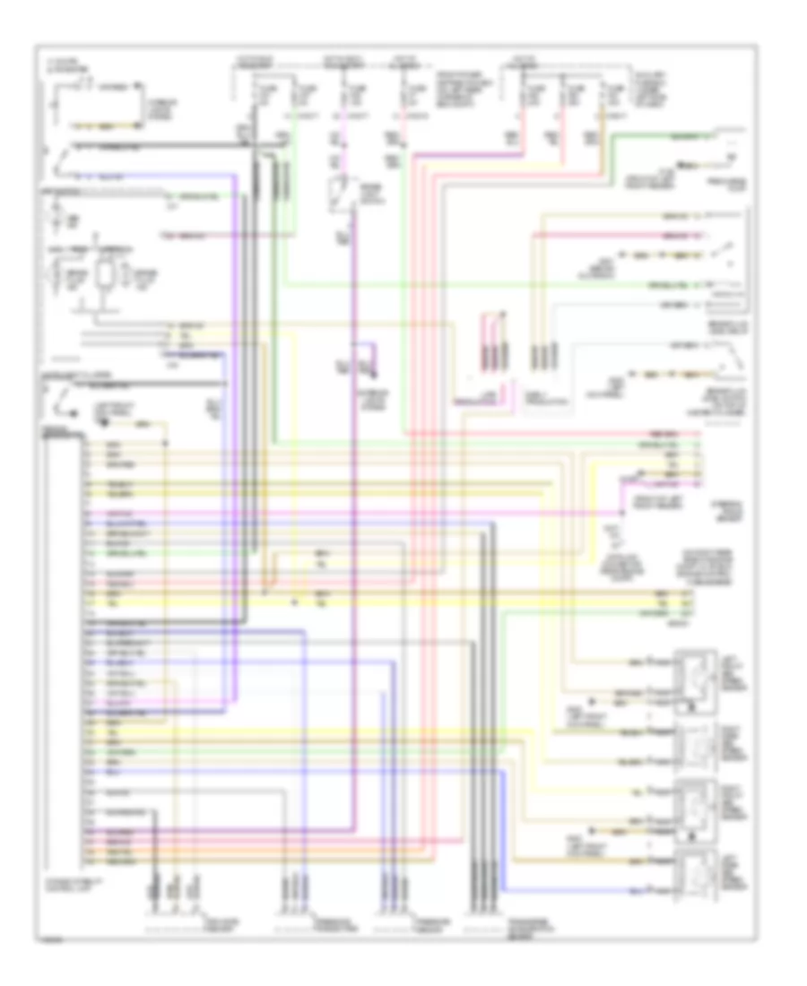
3.2L
3.2L, Manual A/C Wiring Diagram for BMW M Roadster 2000
 https://portal-diagnostov.com/license.html
Automotive Electricians Portal FZCO
Automotive Electricians Portal FZCO
https://portal-diagnostov.com/license.html
https://portal-diagnostov.com/license.html
Automotive Electricians Portal FZCO
Automotive Electricians Portal FZCOList of elements for 3.2L, Manual A/C Wiring Diagram for BMW M Roadster 2000:
- & start
- (behind left footwell speaker grille) g200
- (front left side of engine compartment) g100
- (front right side of engine compartment) g103
- (not used)
- 0.5 0hms
- A/c
- Above 18 bar
- Above 2.6 bar
- Above 30 bar
- Acc
- Air conditioning compressor
- Air conditioning relay, motronic (in front power distribution box)
- Air conditioning/recirculating switch assembly
- All times
- Auxiliary fan motor (behind front grille)
- Auxiliary fuse box (under left side of dash)
- Below 1.5 bar
- Below 15 bar
- Below 21 bar
- Blower motor (on rear of engine compartment, behind right fresh air intake)
- Blower relay (in front power distribution box)
- Blower resistors (behind center of dash)
- Blower switch
- Compressor control relay (in front power distribution box)
- Engine control module (dme) (on right rear side of engine compartment, in "e" box)
- Evaporator controller (on right side of left footwell)
- Evaporator temperature sensor (on right side of left footwell)
- Fresh air recirculation motor (on right side of left footwell)
- Front power distribution box (on left rear corner of engine compartment)
- Fuse 30a
- Fuse 40a
- Fuse 5a
- Fuse 7.5a
- Fuse holder (behind front of center console)
- High speed relay (in front power distribution box)
- Hot at
- Hot at all times
- Hot in run
- Ignition switch
- Nca
- Normal speed relay (in front power distribution box)
- Off
- Pressure switch (on top of receiver-drier, behind right headlight)
- Recirc
- Run
- Start
- Temperature switch (front right side of engine compartment)
- Temperature wheel switch
- Water valve (on rear left side of engine compartment, on firewall)
- X10016
- X10018
- X1588
- X6000
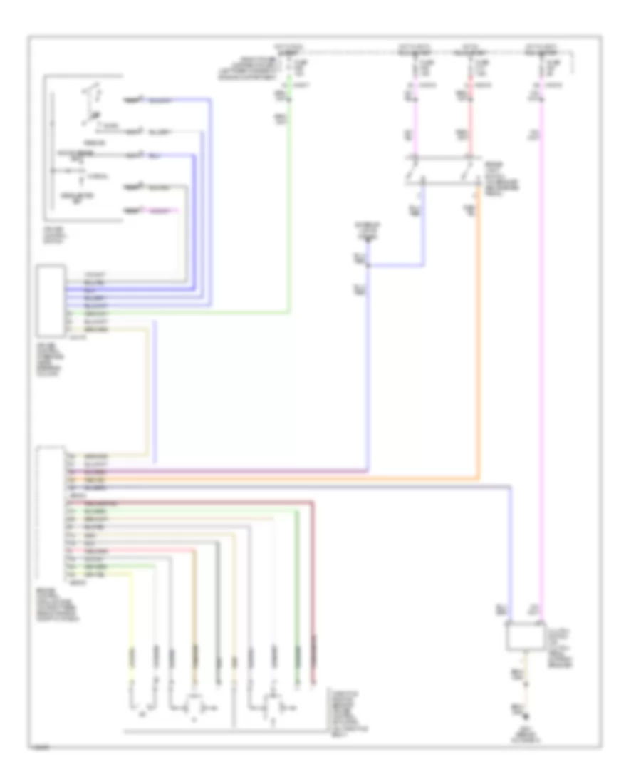
ANTI-LOCK BRAKES
Anti-lock Brakes Wiring Diagram, with Dynamic Stability Control for BMW M Roadster 2000
 https://portal-diagnostov.com/license.html
Automotive Electricians Portal FZCO
Automotive Electricians Portal FZCO
https://portal-diagnostov.com/license.html
https://portal-diagnostov.com/license.html
Automotive Electricians Portal FZCO
Automotive Electricians Portal FZCOList of elements for Anti-lock Brakes Wiring Diagram, with Dynamic Stability Control for BMW M Roadster 2000:
- (front of left front fender)
- (left front kick panel) g200
- (on right rear side of engine compt, in "e" box) engine control module (dme)
- Abs ind
- Auxiliary fuse box (under left side of dash)
- Brake fluid ind
- Brake fluid level relay
- Brake fluid level switch (on top of master cylinder)
- Brake light switch
- Coupe a
- Data link connector (rear engine compt)
- Dsc switch
- Dynamic stability control unit
- Early prod
- Early production
- Exterior lights system
- Front power distribution box (on left rear corner of eng compt)
- Fuse f21 5a
- Fuse f27 5a
- Fuse f46 15a
- Fuse f51 30a
- Fuse f52 30a
- Fuse f53 30a
- Fuse f7 5a
- G100
- G100 (front of left front fender)
- G200 (left front kick panel)
- G200 (left kick panel)
- G201 (behind glove box)
- Hot at all times
- Hot in accy, run & start
- Hot in run and start
- Instrument cluster
- Interior lights system
- Late prod
- Late production
- Left front abs speed sensor
- Left rear abs speed sensor
- Nca
- Parking brake switch
- Precharge pump
- Pressure sensor
- Pressure transmitter
- Right front abs speed sensor
- Right rear abs speed sensor
- Roadster b
- Rpm rate sensor
- Steering angle sensor
- Transverse acceleration sensor
- X10015
- X10017
- X16
- X17
- X19017
- X60004
Anti-lock Brakes Wiring Diagram, with Slip Control for BMW M Roadster 2000
 https://portal-diagnostov.com/license.html
Automotive Electricians Portal FZCO
Automotive Electricians Portal FZCO
https://portal-diagnostov.com/license.html
https://portal-diagnostov.com/license.html
Automotive Electricians Portal FZCO
Automotive Electricians Portal FZCOList of elements for Anti-lock Brakes Wiring Diagram, with Slip Control for BMW M Roadster 2000:
- 2000 coupe a
- 2000 roadster, 2001 b
- Abs ind
- Asc switch
- Brake light switch
- Data link connector (on rear side of engine compt)
- Engine control module (dme) (on right rear side of engine compt, in "e" box)
- Exterior lights system
- Front power distribution box (on left rear corner of engine compartment)
- Fuse f10 30a
- Fuse f21 5a
- Fuse f27 5a
- Fuse f38 30a
- Fuse f46 15a
- G200 (left kick panel)
- Hot at all times
- Hot in accy, run & start
- Hot in run & start
- Instrument cluster
- Interior lights system
- Left front abs speed sensor
- Left rear abs speed sensor
- Nca
- Right front abs speed sensor
- Right rear abs speed sensor
- Slip control module (2.5l, 2.8l : in left front side of engine compt, 3.2l : under right side of dash, behind glove box)
- X10015
- X10017
- X10018
- X16
- X17
- X60004
ANTI-THEFT
Drive-Away Protection Wiring Diagram for BMW M Roadster 2000
 https://portal-diagnostov.com/license.html
Automotive Electricians Portal FZCO
Automotive Electricians Portal FZCO
https://portal-diagnostov.com/license.html
https://portal-diagnostov.com/license.html
Automotive Electricians Portal FZCO
Automotive Electricians Portal FZCOList of elements for Drive-Away Protection Wiring Diagram for BMW M Roadster 2000:
- (below center console) g302
- Acc
- Anti-theft control module (alpine) (behind glove box)
- Automatic transmission range switch (in center console, at shifter)
- Body electronics control module (zke iv) (behind glove box)
- Data link connector (on right rear side of engine compt)
- Electronic immobilizer control module (ews iii) (under left side of dash, left of steering column)
- Engine control module (dme) (on right rear side of engine compt, in "e" box)
- Ews toroidal coil
- Front power distribution box (on left rear corner of engine compt)
- Fuse f28 5a
- Fuse f31 5a
- Fuse f45 7.5a
- G200 (left kick panel)
- Hot at all times
- Hot in accy, run & start
- Hot in run & start
- Ignition switch
- Instrunment cluster system
- Nca
- Off
- Run
- Start
- Starter
- Starter immobilization switch (on left rear side of engine compt)
- Transmission system
- W/o egs
- With egs
- X10017
- X10018
- X1659
- X60004
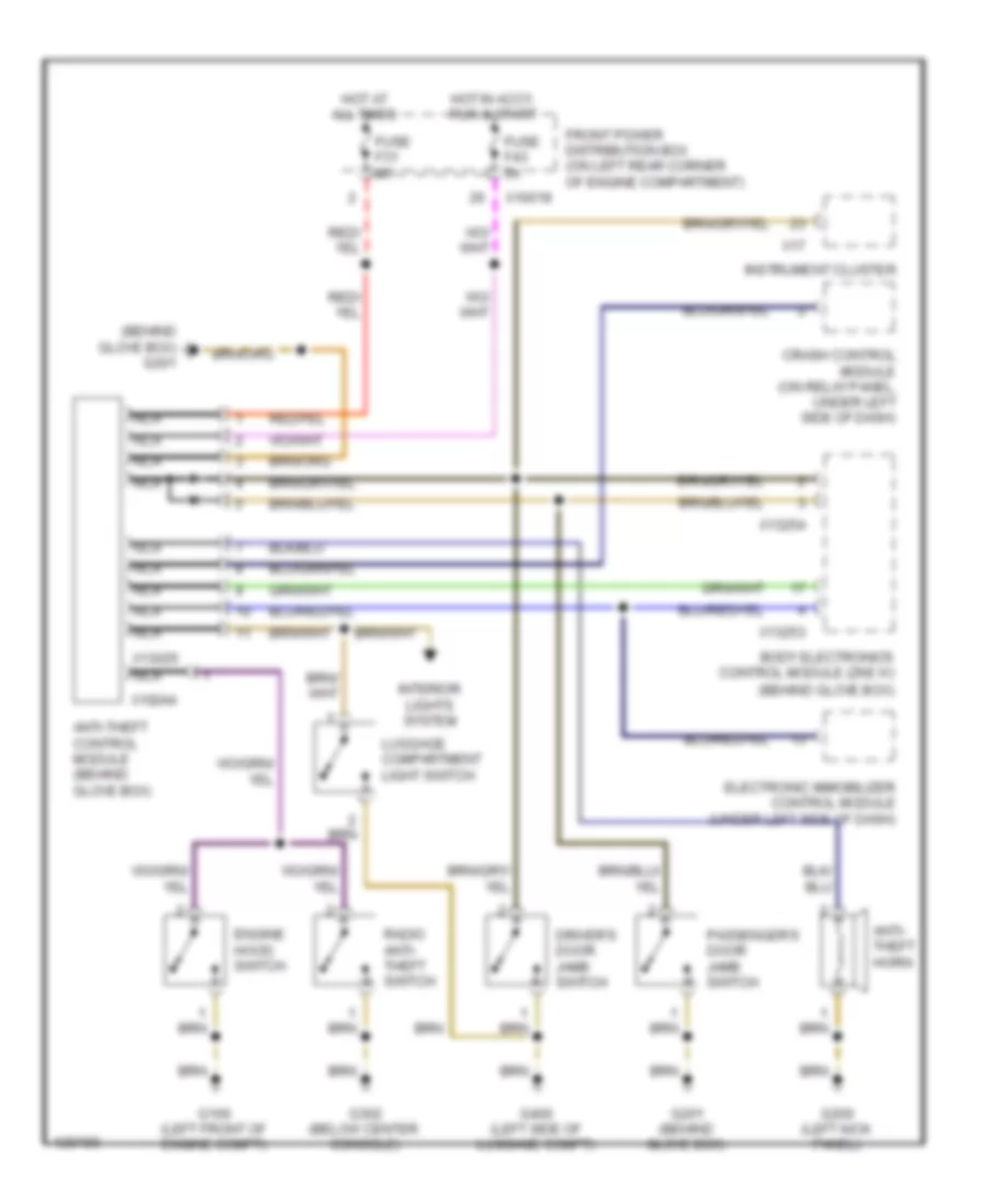
Forced Entry Wiring Diagram for BMW M Roadster 2000
 https://portal-diagnostov.com/license.html
Automotive Electricians Portal FZCO
Automotive Electricians Portal FZCO
https://portal-diagnostov.com/license.html
https://portal-diagnostov.com/license.html
Automotive Electricians Portal FZCO
Automotive Electricians Portal FZCOList of elements for Forced Entry Wiring Diagram for BMW M Roadster 2000:
- (behind glove box) g201
- Anti- theft horn
- Anti-theft control module (behind glove box)
- Body electronics control module (zke iv) (behind glove box)
- Crash control module (on relay panel, under left side of dash)
- Driver's door jamb switch
- Electronic immobilizer control module (under left side of dash)
- Engine hood switch
- Front power distribution box (on left rear corner of engine compartment)
- Fuse f31 5a
- Fuse f43 5a
- G100 (left front of engine compt)
- G200 (left kick panel)
- G201 (behind glove box)
- G302 (below center console)
- G400 (left side of luggage compt)
- Hot at all times
- Hot in accy, run & start
- Instrument cluster
- Interior lights system
- Luggage compartment light switch
- Nca
- Passenger's door jamb switch
- Radio anti- theft switch
- X10018
- X10244
- X13025
- X13253
- X13254
- X17
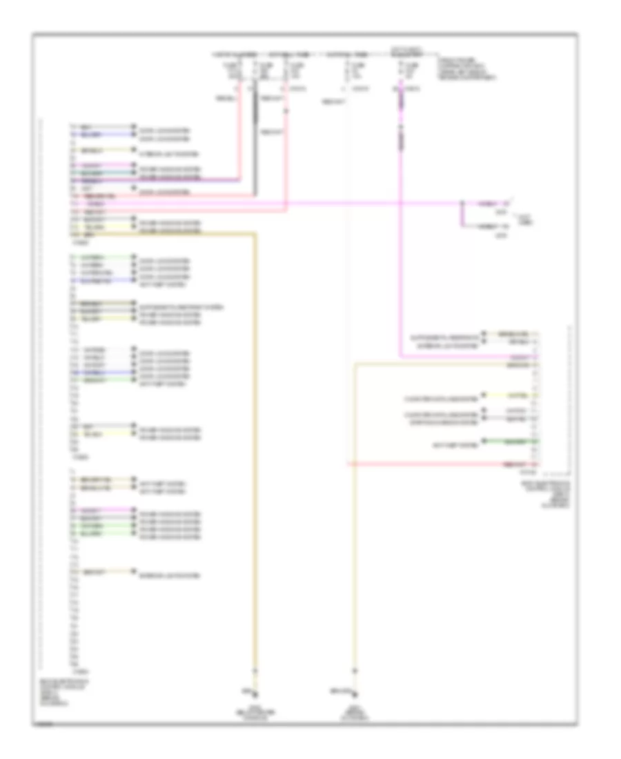
BODY CONTROL MODULES
Body Computer Module Wiring Diagram for BMW M Roadster 2000
 https://portal-diagnostov.com/license.html
Automotive Electricians Portal FZCO
Automotive Electricians Portal FZCO
https://portal-diagnostov.com/license.html
https://portal-diagnostov.com/license.html
Automotive Electricians Portal FZCO
Automotive Electricians Portal FZCOList of elements for Body Computer Module Wiring Diagram for BMW M Roadster 2000:
- (not used)
- Anti-theft system
- Body electronics control module (zke iv) (behind glove box)
- Computer data lines system
- Door locks system
- Exterior lights system
- Front power distribution box (rear left side of engine compartment)
- Fuse f14 30a
- Fuse f2 10a
- Fuse f33 10a
- Fuse f35 25a
- Fuse f43 5a
- G201 (behind glove box)
- G302 (below center console)
- Hot at all times
- Hot in accy, run & start
- Interior lights system
- Power windows system
- Starting/charging system
- X10015
- X10018
- X10182
- X13252
- X13253
- X13254
- X275
- X279
COMPUTER DATA LINES
Computer Data Lines Wiring Diagram for BMW M Roadster 2000
 https://portal-diagnostov.com/license.html
Automotive Electricians Portal FZCO
Automotive Electricians Portal FZCO
https://portal-diagnostov.com/license.html
https://portal-diagnostov.com/license.html
Automotive Electricians Portal FZCO
Automotive Electricians Portal FZCOList of elements for Computer Data Lines Wiring Diagram for BMW M Roadster 2000:
- (behind
- (behind center console)
- (behind glove box) body electronics control module (zke iv)
- (below center console)
- (right rear side of engine compartment) data link connector
- Battery
- Board computer
- Dynamic stability control unit (left side of engine compt)
- Electronic immobilizer control module (under left side of dash)
- Engine control module (dme) (right rear side of engine compartment, in "e" box)
- Front power distribution box (left rear corner of engine compartment)
- Fuse f26 10a
- Fuse f31 5a
- G108 (left front of engine compt)
- G201
- G302
- Glove box)
- Hot at all times
- Hot in run & start
- Instrument cluster
- Obd ii connector (right side of center console)
- Red
- Slip control module (left front of engine compartment)
- Steering angle sensor (on base of steering column)
- Thermal oil level sensor (toens) control module (behind glove box)
- Transmission control module (egs) (right rear side of engine compartment, in "e" box)
- W/ dsc
- X10182
- X10245
- X16
- X17
- X1805
- X60004
- X74
- X8500
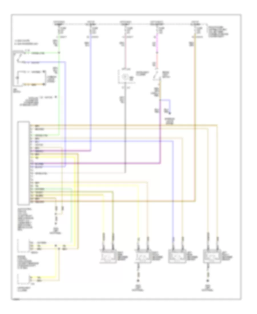
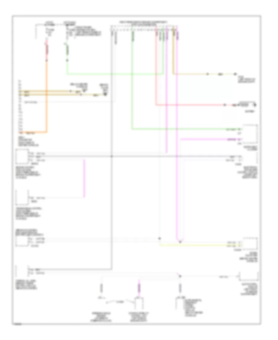
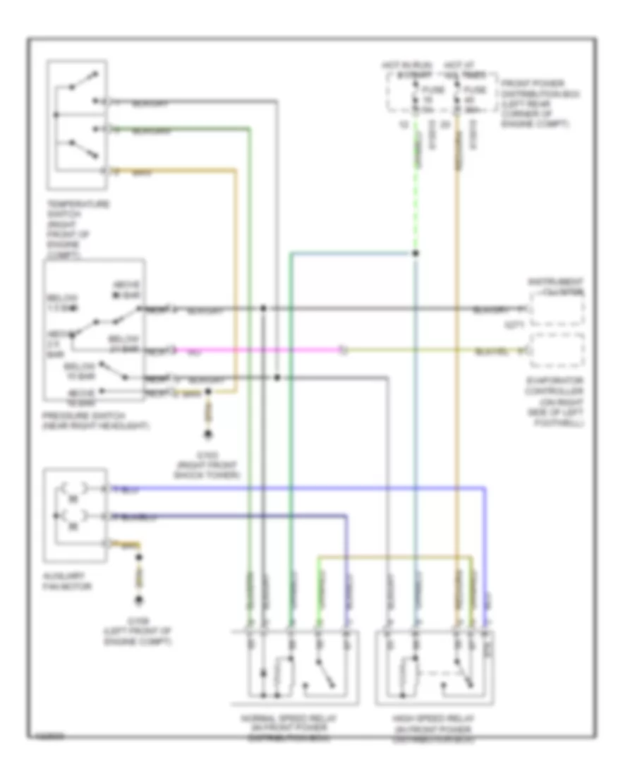
COOLING FAN
Cooling Fan Wiring Diagram for BMW M Roadster 2000
 https://portal-diagnostov.com/license.html
Automotive Electricians Portal FZCO
Automotive Electricians Portal FZCO
https://portal-diagnostov.com/license.html
https://portal-diagnostov.com/license.html
Automotive Electricians Portal FZCO
Automotive Electricians Portal FZCOList of elements for Cooling Fan Wiring Diagram for BMW M Roadster 2000:
- (on right side of left footwell)
- 87a
- Above 18 bar
- Above 2.6 bar
- Above 30 bar
- Auxiliary fan motor
- Below 1.5 bar
- Below 15 bar
- Below 21 bar nca
- Evaporator controller
- Front power distribution box (left rear corner of engine compt)
- Fuse 30a
- Fuse 5a
- G103 (right front shock tower)
- G108 (left front of engine compt)
- High speed relay (in front power distribution box)
- Hot at all times
- Hot in run & start
- Instrument cluster
- Nca
- Normal speed relay (in front power distribution box)
- Pressure switch (near right headlight)
- Temperature switch (right front of engine compt)
- X10016
- X10018
- X271
CRUISE CONTROL
Cruise Control Wiring Diagram for BMW M Roadster 2000
 https://portal-diagnostov.com/license.html
Automotive Electricians Portal FZCO
Automotive Electricians Portal FZCO
https://portal-diagnostov.com/license.html
https://portal-diagnostov.com/license.html
Automotive Electricians Portal FZCO
Automotive Electricians Portal FZCOList of elements for Cruise Control Wiring Diagram for BMW M Roadster 2000:
- Acccelerate/ set
- Brake- light switch (on bracket above brake pedal)
- Clutch switch (on clutch pedal support bracket)
- Cruise control interface (near steering column)
- Cruise control switch
- Decelerate/ set
- Engine control module (dme) (on right rear side of engine compt in "e" box)
- Exterior lights system
- Front power distribution box (left rear corner of engine compartment)
- Fuse f13 7.5a
- Fuse f26 10a
- Fuse f43 5a
- Fuse f46 15a
- G201 (behind glove box)
- Hot in accy, run & start
- Hot in run & start
- Nca
- Norm
- Normal
- Off
- Resume
- Throttle positon sensor/ cruise control actuator (on throttle body)
- X10016
- X10017
- X10018
- X10170
- X60003
- X60004
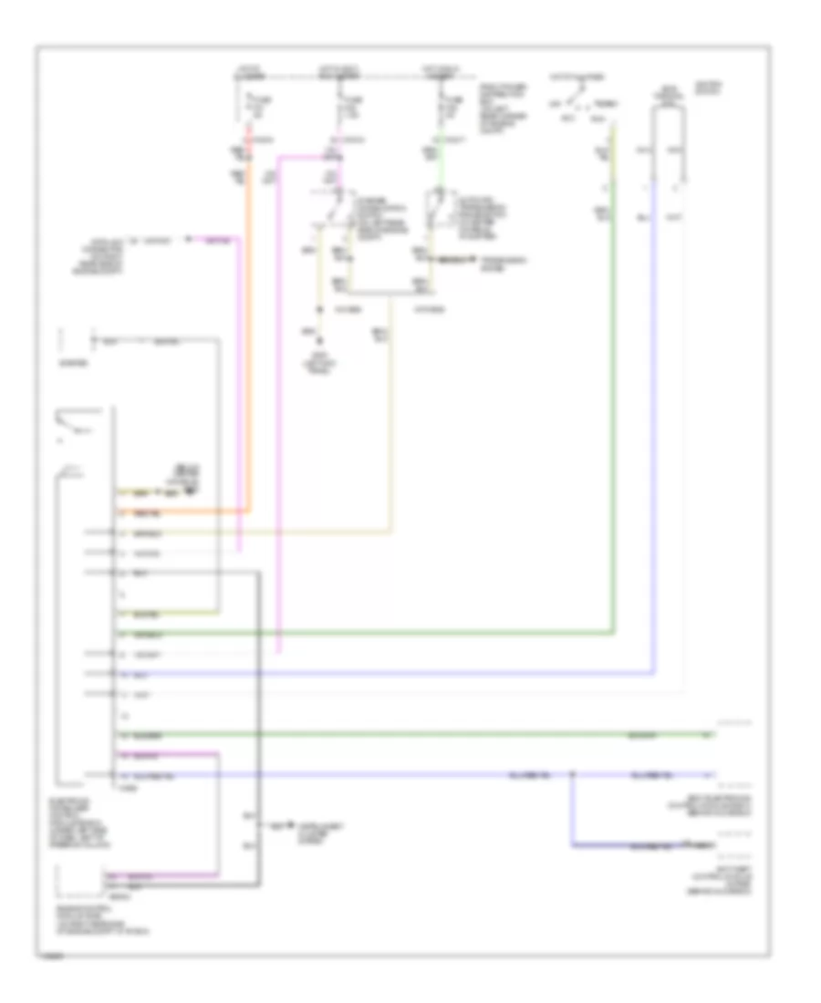
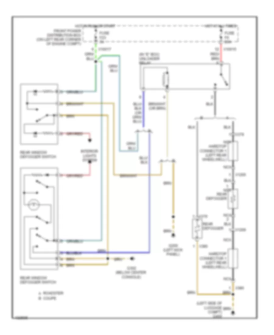
DEFOGGERS
Defoggers Wiring Diagram for BMW M Roadster 2000
 https://portal-diagnostov.com/license.html
Automotive Electricians Portal FZCO
Automotive Electricians Portal FZCO
https://portal-diagnostov.com/license.html
https://portal-diagnostov.com/license.html
Automotive Electricians Portal FZCO
Automotive Electricians Portal FZCOList of elements for Defoggers Wiring Diagram for BMW M Roadster 2000:
- (in "e" box) unloader relay
- (left side of luggage compt) g400
- Coupe b
- Front power distribution box (on left rear corner of engine compt)
- Fuse f23 5a
- Fuse f6 20a
- G200 (left kick panel)
- G302 (below center console)
- Hardtop connector 1 (left rear wheelwell)
- Hot at all times
- Hot in run or start
- Interior lights system
- Nca
- Rear defogger
- Rear window defogger switch
- Roadster a
- X10015
- X10017
- X1265
- X1266
- X379
- X380
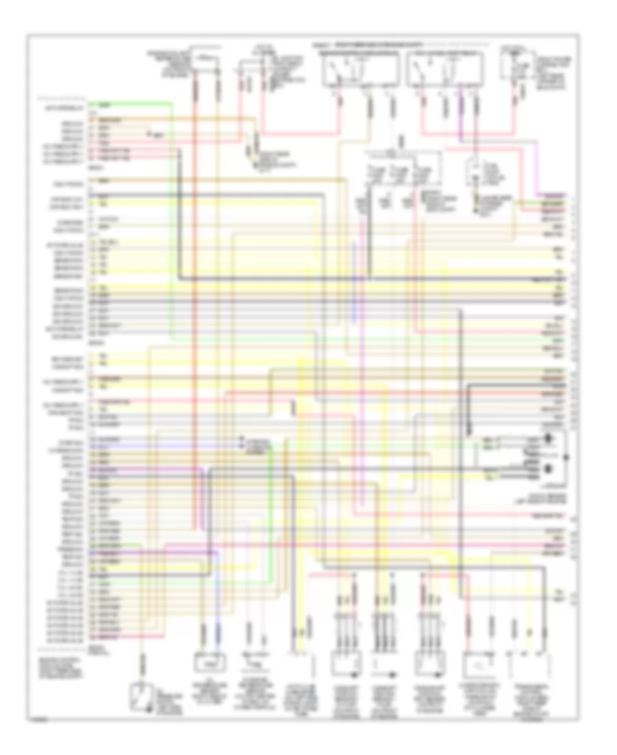
ENGINE PERFORMANCE
2.5L
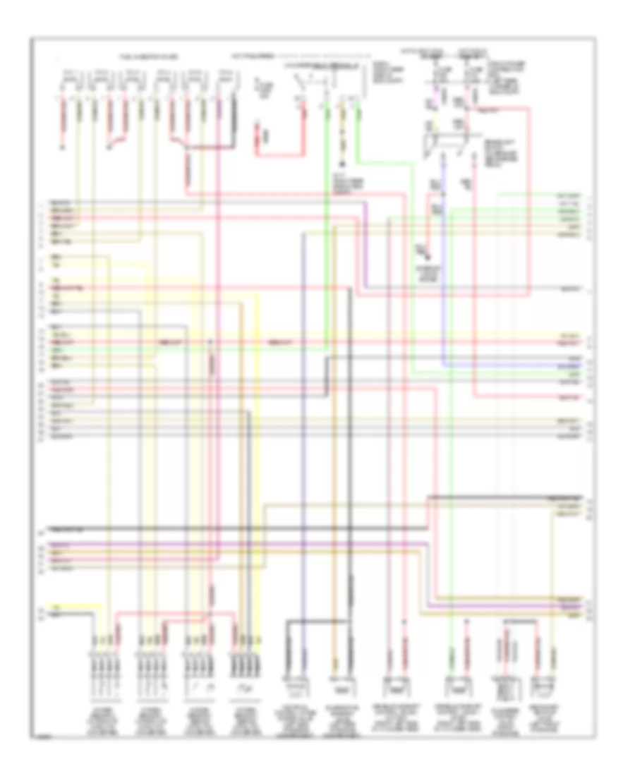
2.5L, Engine Performance Wiring Diagram (1 of 3) for BMW M Roadster 2000
 https://portal-diagnostov.com/license.html
Automotive Electricians Portal FZCO
Automotive Electricians Portal FZCO
https://portal-diagnostov.com/license.html
https://portal-diagnostov.com/license.html
Automotive Electricians Portal FZCO
Automotive Electricians Portal FZCOList of elements for 2.5L, Engine Performance Wiring Diagram (1 of 3) for BMW M Roadster 2000:
- (right rear side of engine compt)
- (right rear side of engine compt) g117
- (under rear storage compt) g311
- 2-3
- 8-11
- Activate relay
- Activate valve
- Air mass met
- B+ junction point e-box (in front power distribution box)
- Camshaft position sensor 1 (inlet) (on front of engine)
- Camshaft position sensor 2 (outlet) (on front of engine)
- Camshft sig
- Can bus high
- Can bus low
- Characteristic map cooling thermostat (on front of cylinder head)
- Charging sig
- Crankshaft position/ rpm sensor (on front of engine)
- Crnkshft sig
- Cyl 1-3
- Cyl 1-3 ks
- Cyl 1-6 fuel pump relay
- Cyl 4-6 ks
- Cyl 4-6 nca
- Diagnosis
- E-box
- E-box (right rear side of eng compt)
- Engine control module (dme) (right rear side of engine compt)
- Engine control module relay
- Engine coolant temperature sensor (on front of engine)
- Front power distribution box (left rear corner of eng compt)
- Fuel pump (in fuel tank)
- Fuse f18 15a
- Fuse f202 30a
- Fuse f203 20a
- Fuse f204 30a
- Ground
- Hot at all times
- Hot film air mass meter (on left side of eng compt, on air intake tube)
- Intake air temperature sensor (on top center of eng, on intake manifold)
- Knock sensor (left side of engine)
- Nca
- O2s htd sig
- O2s htg sig
- Oil pressure switch (left side of engine)
- Oil temperature sensor (right side of oil filter)
- Press sig
- Red
- Sensor sig
- Sig ground
- Start sig
- Starting/ charging system
- Temp sig
- Tp sig
- Transmission control module (egs) (right rear side of engine compt, in e-box)
- X10016
- X60001
- X60002
- X60003 (partial)
- X64101
- X64102
- X8680
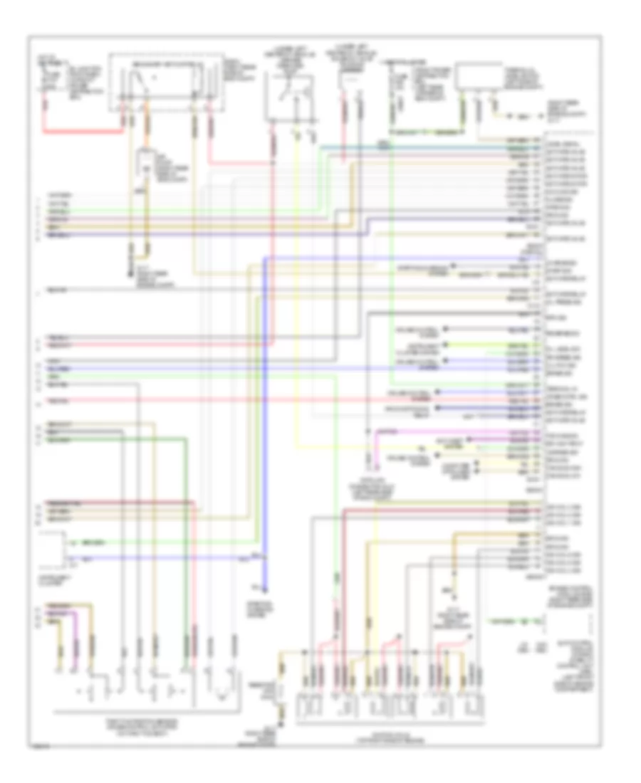
2.5L, Engine Performance Wiring Diagram (2 of 3) for BMW M Roadster 2000
 https://portal-diagnostov.com/license.html
Automotive Electricians Portal FZCO
Automotive Electricians Portal FZCO
https://portal-diagnostov.com/license.html
https://portal-diagnostov.com/license.html
Automotive Electricians Portal FZCO
Automotive Electricians Portal FZCOList of elements for 2.5L, Engine Performance Wiring Diagram (2 of 3) for BMW M Roadster 2000:
- Brakelight switch (on bracket, above brake pedal)
- Cyl 1
- Cyl 2
- Cyl 3
- Cyl 4
- Cyl 5
- Cyl 6
- E-box (right rear side of eng compt)
- Evaporative emission valve (left side of engine compartment)
- Exterior lights system
- Front power distribution box (left rear corner of eng compt)
- Fuel injection valves
- Fuse f13 7.5a
- Fuse f205 30a
- Fuse f46 15a
- G117 (right rear side of eng compt)
- Hot at all times
- Hot in accy, run or start
- Hot in run or start
- Idle speed control valve (front of engine)
- Individual control intake system valve (left side of engine compartment)
- Nca
- Oxygen sensor 1 (behind catalytic converter)
- Oxygen sensor 1 (in front of catalytic converter)
- Oxygen sensor 2 (behind catalytic converter)
- Oxygen sensor 2 (in front of catalytic converter)
- Red
- Secondary air pump valve (left front of engine)
- Unloader relay terminal 15
- Variable camshaft control valve 1 (inlet) (front left side of cylinder head)
- Variable camshaft control valve 2 (outlet) (front left side of cylinder head)
- X10018
- X9680
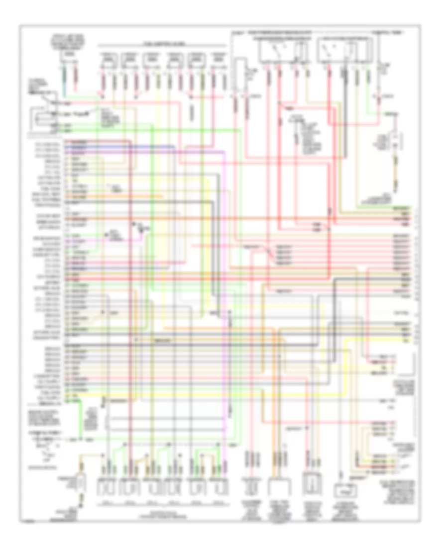
2.5L, Engine Performance Wiring Diagram (3 of 3) for BMW M Roadster 2000
 https://portal-diagnostov.com/license.html
Automotive Electricians Portal FZCO
Automotive Electricians Portal FZCO
https://portal-diagnostov.com/license.html
https://portal-diagnostov.com/license.html
Automotive Electricians Portal FZCO
Automotive Electricians Portal FZCOList of elements for 2.5L, Engine Performance Wiring Diagram (3 of 3) for BMW M Roadster 2000:
- (right rear side of engine compt) g117
- (under left center of vehicle) leakage diagnosis pump
- (under left center of vehicle) solenoid valve (running losses)
- (w/ dsc)
- (w/o dsc)
- 12-16
- 38-40
- 4-9
- 50-51
- Activate motor
- Activate relay
- Activate valve
- Air conditioning relay
- Air pump (right rear side of eng compt)
- Anti-theft system
- B+ junction point e-box (in front power distribution box)
- Brake sig
- Can bus high
- Can bus low
- Charge sig
- Close sig
- Clutch sig
- Computer data lines system
- Cooling sig
- Crse cntrl sig
- Cruise control system
- Data link connector (dlc) (left rear side of eng compt)
- Drv awy prot
- E-box (right rear side of eng compt)
- Engine control module (dme) (right rear side of engine compt)
- Front power distribution box (left rear corner of eng compt)
- Fuse f107 50a
- Fuse f26 10a
- G117 (right rear side of engine compt)
- Ground
- Hot at all times
- Ign coil 1 sig
- Ign coil 2 sig
- Ign coil 3 sig
- Ign coil 4 sig
- Ign coil 5 sig
- Ign coil 6 sig
- Ignition coils (top right side of engine)
- Instrument cluster
- Instrument cluster system
- Leakage sig
- Level signal
- Nca
- Oil level sig
- Oil press sig
- Open sig
- Red
- Resistor (240 ohm)
- Reverse sig
- Rpm sig
- Rr speed sig
- Secondary air pump relay
- Slip control module/ dynamic stability control unit (dsc) (left front side of engine compartment)
- Start sig
- Starting/ charging system
- Starting/charging system
- Terminal 15
- Thermal oil level switch (left side of engine compt)
- Throttle position sensor/ cruise control actuator (on throttle body)
- Txd diag sig
- X10017
- X17
- X60003 (partial)
- X60004
- X60005
2.8L
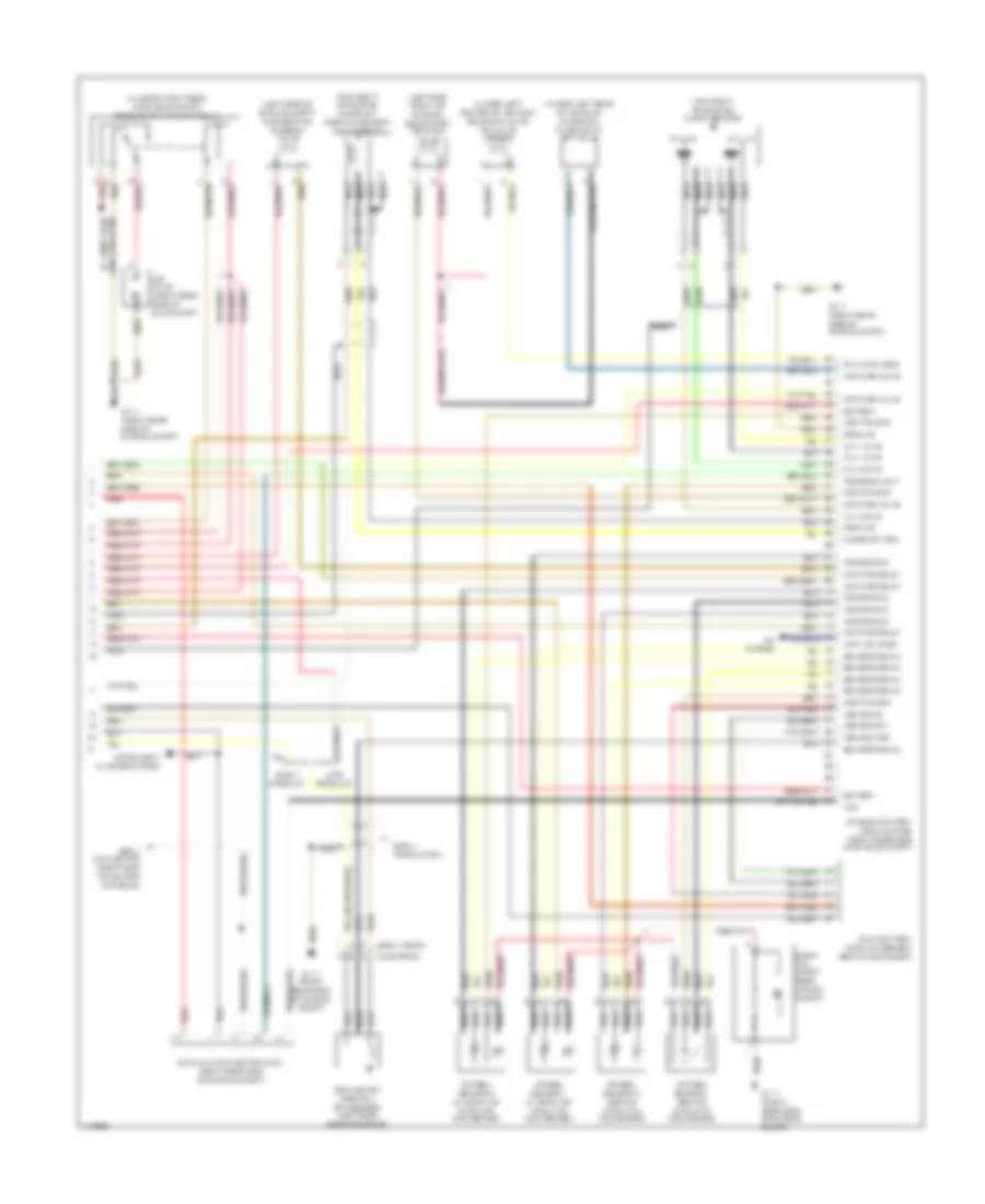
2.8L, Engine Performance Wiring Diagram (1 of 3) for BMW M Roadster 2000
 https://portal-diagnostov.com/license.html
Automotive Electricians Portal FZCO
Automotive Electricians Portal FZCO
https://portal-diagnostov.com/license.html
https://portal-diagnostov.com/license.html
Automotive Electricians Portal FZCO
Automotive Electricians Portal FZCOList of elements for 2.8L, Engine Performance Wiring Diagram (1 of 3) for BMW M Roadster 2000:
- (right rear side of engine compt)
- (right rear side of engine compt) g117
- (under rear storage compt) g311
- 2-3
- 8-11
- Activate relay
- Activate valve
- Air mass met
- B+ junction point e-box (in front power distribution box)
- Camshaft position sensor 1 (inlet) (on front of engine)
- Camshaft position sensor 2 (outlet) (on front of engine)
- Camshft sig
- Can bus high
- Can bus low
- Characteristic map cooling thermostat (on front of cylinder head)
- Charging sig
- Crankshaft position/ rpm sensor (on front of engine)
- Crnkshft sig
- Cyl 1-3
- Cyl 1-3 ks
- Cyl 1-6 fuel pump relay
- Cyl 4-6 ks
- Cyl 4-6 nca
- Diagnosis
- E-box
- E-box (right rear side of eng compt)
- Engine control module (dme) (right rear side of engine compt)
- Engine control module relay
- Engine coolant temperature sensor (on front of engine)
- Front power distribution box (left rear corner of eng compt)
- Fuel pump (in fuel tank)
- Fuse f18 15a
- Fuse f202 30a
- Fuse f203 20a
- Fuse f204 30a
- Ground
- Hot at all times
- Hot film air mass meter (on left side of eng compt, on air intake tube)
- Intake air temperature sensor (on top center of eng, on intake manifold)
- Knock sensor (left side of engine)
- Nca
- O2s htd sig
- O2s htg sig
- Oil pressure switch (left side of engine)
- Oil temperature sensor (right side of oil filter)
- Press sig
- Red
- Sensor sig
- Sig ground
- Start sig
- Starting/ charging system
- Temp sig
- Tp sig
- Transmission control module (egs) (right rear side of engine compt, in e-box)
- X10016
- X60001
- X60002
- X60003 (partial)
- X64101
- X64102
- X8680
2.8L, Engine Performance Wiring Diagram (2 of 3) for BMW M Roadster 2000
 https://portal-diagnostov.com/license.html
Automotive Electricians Portal FZCO
Automotive Electricians Portal FZCO
https://portal-diagnostov.com/license.html
https://portal-diagnostov.com/license.html
Automotive Electricians Portal FZCO
Automotive Electricians Portal FZCOList of elements for 2.8L, Engine Performance Wiring Diagram (2 of 3) for BMW M Roadster 2000:
- Brakelight switch (on bracket, above brake pedal)
- Cyl 1
- Cyl 2
- Cyl 3
- Cyl 4
- Cyl 5
- Cyl 6
- E-box (right rear side of eng compt)
- Evaporative emission valve (left side of engine compartment)
- Exterior lights system
- Front power distribution box (left rear corner of eng compt)
- Fuel injection valves
- Fuse f13 7.5a
- Fuse f205 30a
- Fuse f46 15a
- G117 (right rear side of eng compt)
- Hot at all times
- Hot in accy, run or start
- Hot in run or start
- Idle speed control valve (front of engine)
- Individual control intake system valve (left side of engine compartment)
- Nca
- Oxygen sensor 1 (behind catalytic converter)
- Oxygen sensor 1 (in front of catalytic converter)
- Oxygen sensor 2 (behind catalytic converter)
- Oxygen sensor 2 (in front of catalytic converter)
- Red
- Secondary air pump valve (left front of engine)
- Unloader relay terminal 15
- Variable camshaft control valve 1 (inlet) (front left side of cylinder head)
- Variable camshaft control valve 2 (outlet) (front left side of cylinder head)
- X10018
- X9680
2.8L, Engine Performance Wiring Diagram (3 of 3) for BMW M Roadster 2000
 https://portal-diagnostov.com/license.html
Automotive Electricians Portal FZCO
Automotive Electricians Portal FZCO
https://portal-diagnostov.com/license.html
https://portal-diagnostov.com/license.html
Automotive Electricians Portal FZCO
Automotive Electricians Portal FZCOList of elements for 2.8L, Engine Performance Wiring Diagram (3 of 3) for BMW M Roadster 2000:
- (right rear side of engine compt) g117
- (under left center of vehicle) leakage diagnosis pump
- (under left center of vehicle) solenoid valve (running losses)
- (w/ dsc)
- (w/o dsc)
- 12-16
- 38-40
- 4-9
- 50-51
- Activate motor
- Activate relay
- Activate valve
- Air conditioning relay
- Air pump (right rear side of eng compt)
- Anti-theft system
- B+ junction point e-box (in front power distribution box)
- Brake sig
- Can bus high
- Can bus low
- Charge sig
- Close sig
- Clutch sig
- Computer data lines system
- Cooling sig
- Crse cntrl sig
- Cruise control system
- Data link connector (dlc) (left rear side of eng compt)
- Drv awy prot
- E-box (right rear side of eng compt)
- Engine control module (dme) (right rear side of engine compt)
- Front power distribution box (left rear corner of eng compt)
- Fuse f107 50a
- Fuse f26 10a
- G117 (right rear side of engine compt)
- Ground
- Hot at all times
- Ign coil 1 sig
- Ign coil 2 sig
- Ign coil 3 sig
- Ign coil 4 sig
- Ign coil 5 sig
- Ign coil 6 sig
- Ignition coils (top right side of engine)
- Instrument cluster
- Instrument cluster system
- Leakage sig
- Level signal
- Nca
- Oil level sig
- Oil press sig
- Open sig
- Red
- Resistor (240 ohm)
- Reverse sig
- Rpm sig
- Rr speed sig
- Secondary air pump relay
- Slip control module/ dynamic stability control unit (dsc) (left front side of engine compartment)
- Start sig
- Starting/ charging system
- Starting/charging system
- Terminal 15
- Thermal oil level switch (left side of engine compt)
- Throttle position sensor/ cruise control actuator (on throttle body)
- Txd diag sig
- X10017
- X17
- X60003 (partial)
- X60004
- X60005
3.2L
3.2L, Engine Performance Wiring Diagram (1 of 2) for BMW M Roadster 2000
 https://portal-diagnostov.com/license.html
Automotive Electricians Portal FZCO
Automotive Electricians Portal FZCO
https://portal-diagnostov.com/license.html
https://portal-diagnostov.com/license.html
Automotive Electricians Portal FZCO
Automotive Electricians Portal FZCOList of elements for 3.2L, Engine Performance Wiring Diagram (1 of 2) for BMW M Roadster 2000:
- (front left side of cylinder head) variable camshaft control valve 1
- (in e-box) unloader relay terminal 15
- (not used)
- (right rear side of engine compt)
- A/c on sig
- A/c system
- Acc
- Activate a/c
- Activate valve
- Anti- theft system
- B+ jump start junction point (right rear side of engine compt)
- Battery
- Camshaft ctrl
- Camshaft pos
- Chekc eng ind
- Crnkshft rpm
- Cyl 1
- Cyl 1 ign coil
- Cyl 1 inj
- Cyl 1-6 fuel pump relay
- Cyl 2
- Cyl 2 ign coil
- Cyl 2 inj
- Cyl 3
- Cyl 3 ign coil
- Cyl 3 inj
- Cyl 4
- Cyl 4 ign coil
- Cyl 4 inj
- Cyl 5
- Cyl 5 ign coil
- Cyl 5 inj
- Cyl 6
- Cyl 6 ign coil
- Cyl 6 inj
- Drive-away sig
- Dual temperature sensor (coolant temperature) (left front of engine, below intake manifold)
- E-box
- Eng cool temp
- Engine control module (dme) (right rear side of engine compt)
- Engine control module relay
- Fuel cons
- Fuel injection valves
- Fuel pump (in fuel tank)
- Fuel tank pressure sensor (under rear of storage compt)
- Fuel tnk press
- Fuse f13 5a
- Fuse f18 15a
- G117 (right rear side of engine compt)
- G311 (under rear storage compt)
- Ground
- Hot at all times
- Hot fam mtr
- Hot film air mass meter (left side of engine)
- Idle speed control valve (front of engine)
- Ignition coils (top right side of engine)
- Ignition switch
- Instrument cluster
- Intake air temperature sensor (left side of engine compt)
- Intk air temp
- Nca
- Off
- Red
- Resistor (240 ohm)
- Run
- Speed sig rr
- Start
- Terminal 15
- Throt pos sig
- Throttle pos
- Throttle position sensor (throttle body)
- X10016
- X16
- X17
3.2L, Engine Performance Wiring Diagram (2 of 2) for BMW M Roadster 2000
 https://portal-diagnostov.com/license.html
Automotive Electricians Portal FZCO
Automotive Electricians Portal FZCO
https://portal-diagnostov.com/license.html
https://portal-diagnostov.com/license.html
Automotive Electricians Portal FZCO
Automotive Electricians Portal FZCOList of elements for 3.2L, Engine Performance Wiring Diagram (2 of 2) for BMW M Roadster 2000:
- (early prod)
- (in e-box, right rear of engine compt) secondary air pump relay
- (late prod)
- (left side front of engine) secondary air pump valve
- (left side of engine compt) evaporative emission valve
- (top front of engine) camshaft position sensor (cylinder id)
- (top front of engine) knock sensor
- (under left center of vehicle) solenoid valve (running losses)
- (under left rear of vehicle) charcoal filter shut off valve
- 02s htg gnd
- 02s sig gnd
- A/c system
- Activate relay
- Activate valve
- Actv a/c comp
- Air pump (right rear side of eng compt)
- Asc-sig mcr
- Asc-sig za
- Asc-sig zwv
- B+ jump start junction point
- Battery
- Camshaft pos
- Crankshaft position/ rpm sensor (left rear side of engine)
- Cyl 1-3
- Cyl 1-3 ks
- Cyl 4-6
- Cyl 4-6 ks
- Data link connector (dlc) (right rear side of engine compt)
- E-box fan (right rear of eng compt)
- Early product
- Early production
- Engine control module (dme) (right rear side of engine compt)
- G117 (right rear side of engine compt)
- Ground
- Instrument cluster system
- Late product
- Nca
- Obd ii connector (right side of center console)
- Oxygen sensor 1 (behind catalytic converter)
- Oxygen sensor 1 (in front of catalytic converter)
- Oxygen sensor 2 (behind catalytic converter)
- Oxygen sensor 2 (in front of catalytic converter)
- Program volt
- Red
- Running loss
- Sensor signal
- Slip control module (abs/asc) (behind glove box)
- Txd
EXTERIOR LIGHTS
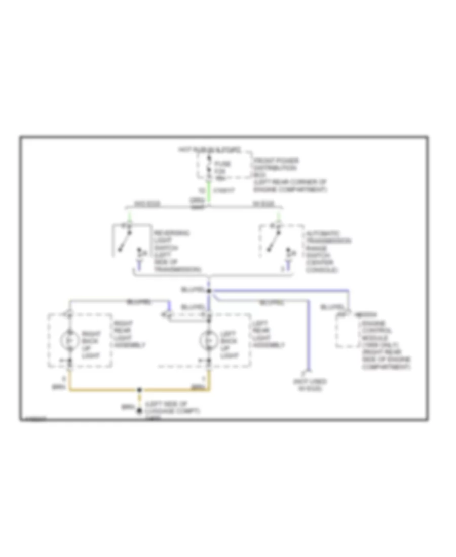
Backup Lamps Wiring Diagram for BMW M Roadster 2000
 https://portal-diagnostov.com/license.html
Automotive Electricians Portal FZCO
Automotive Electricians Portal FZCO
https://portal-diagnostov.com/license.html
https://portal-diagnostov.com/license.html
Automotive Electricians Portal FZCO
Automotive Electricians Portal FZCOList of elements for Backup Lamps Wiring Diagram for BMW M Roadster 2000:
- (left side of luggage compt) g400
- (not used w/ egs)
- Automatic transmission range switch (center console)
- Engine control module (1999 only) (right rear side of engine compartment)
- Front power distribution box (left rear corner of engine compartment)
- Fuse f26 10a
- Hot in run & start
- Left back up light
- Left rear light assembly
- Reversing light switch (left side of transmission)
- Right back up light
- Right rear light assembly
- W/ egs
- W/o egs
- X10017
- X60004
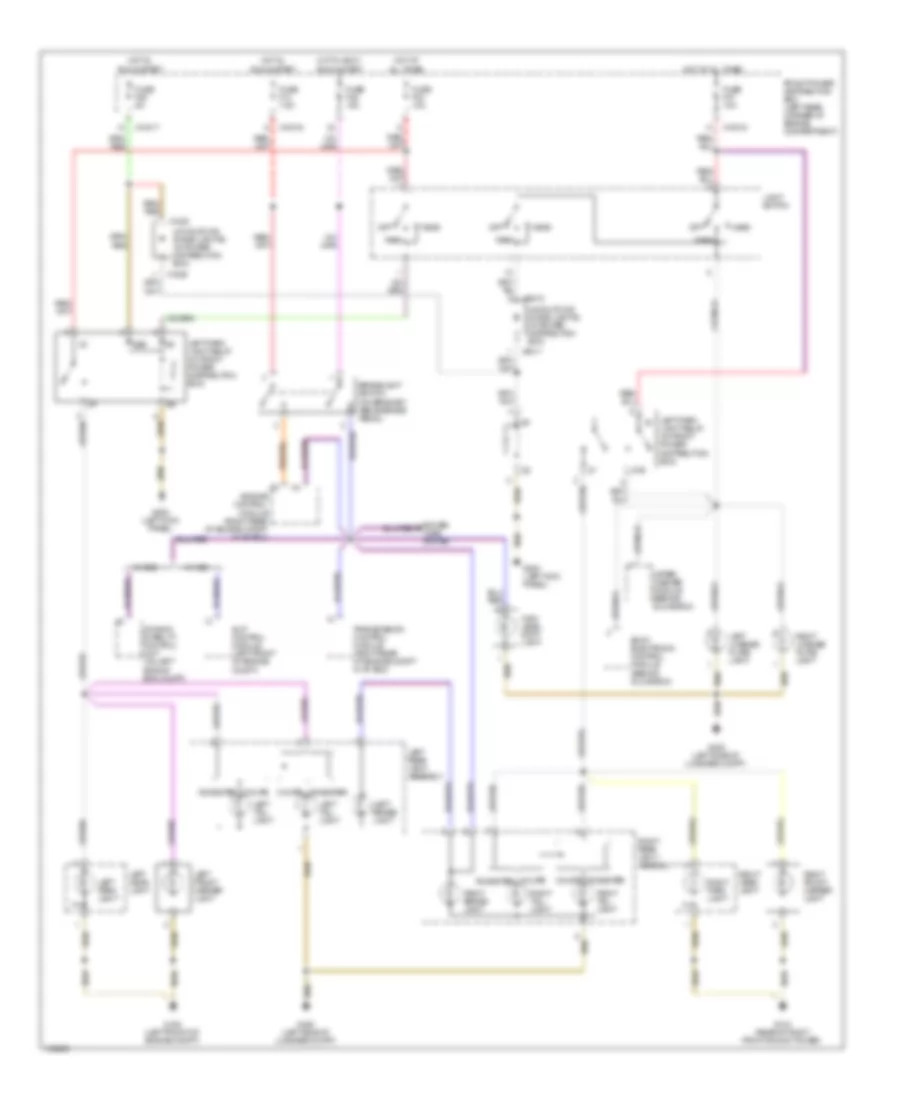
Park, Stop, Tail & License Plate Lamps Wiring Diagram, Canada Late Production for BMW M Roadster 2000
 https://portal-diagnostov.com/license.html
Automotive Electricians Portal FZCO
Automotive Electricians Portal FZCO
https://portal-diagnostov.com/license.html
https://portal-diagnostov.com/license.html
Automotive Electricians Portal FZCO
Automotive Electricians Portal FZCOList of elements for Park, Stop, Tail & License Plate Lamps Wiring Diagram, Canada Late Production for BMW M Roadster 2000:
- 86b
- 87b
- Body electronic control module (behind glove box)
- Brakelight switch (on bracket, above brake pedal)
- Coupe roadster
- Dynamic stability control unit (on left side of eng compt)
- Engine control module (right rear of engine compt in "e" box)
- Front power distribution box (left rear corner of engine compartment)
- Fuse f13 7.5a
- Fuse f25 5a
- Fuse f33 10a
- Fuse f37 10a
- Fuse f46 15a
- G103 (rear of right front shock tower)
- G108 (left front of engine compt)
- G200 (left kick panel)
- G400 (left side of luggage compt)
- Head
- High level stop light
- Hot at all times
- Hot in accy, run & start
- Hot in, run & start
- Left brake- light
- Left front marker light
- Left head- light
- Left license plate light
- Left park light
- Left park light relay (in front power distribution box)
- Left rear light assembly
- Left tail- light
- Light switch
- Off
- Park
- Power tops system
- Right brake- light
- Right front marker light
- Right head- light
- Right license plate light
- Right park light
- Right rear light assembly
- Right tail- light
- Roadster coupe
- Slip control module (left front of engine compt)
- Transmission control module (right rear of engine compt in "e" box)
- Uncoupling diode (lights) (in power distribution box)
- W/ asc
- W/ dsc
- Wiper/ washer module (behind glove box)
- X10016
- X10017
- X10018
- X1529
- X1530
- X9410
- X9411
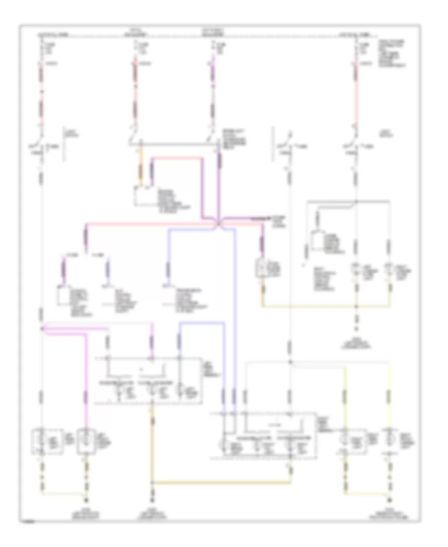
Park, Stop, Tail & License Plate Lamps Wiring Diagram, USA & Canada Early Production for BMW M Roadster 2000
 https://portal-diagnostov.com/license.html
Automotive Electricians Portal FZCO
Automotive Electricians Portal FZCO
https://portal-diagnostov.com/license.html
https://portal-diagnostov.com/license.html
Automotive Electricians Portal FZCO
Automotive Electricians Portal FZCOList of elements for Park, Stop, Tail & License Plate Lamps Wiring Diagram, USA & Canada Early Production for BMW M Roadster 2000:
- Body electronic control module (behind glove box)
- Brakelight switch (on bracket, above brake pedal)
- Coupe roadster
- Dynamic stability control unit (on left side of eng compt)
- Engine control module (right rear of engine compt in "e" box)
- Front power distribution box (left rear corner of engine compartment)
- Fuse f13 7.5a
- Fuse f33 10a
- Fuse f37 10a
- Fuse f46 15a
- G103 (rear of right front shock tower)
- G108 (left front of engine compt)
- G400 (left side of luggage compt)
- Head
- High level stop light
- Hot at all times
- Hot in accy, run & start
- Hot in, run & start
- Left brake- light
- Left front marker light
- Left head- light
- Left license plate light
- Left park light
- Left rear light assembly
- Left tail- light
- Light switch
- Off
- Park
- Power tops system
- Right brake- light
- Right front marker light
- Right head- light
- Right license plate light
- Right park light
- Right rear light assembly
- Right tail- light
- Roadster coupe
- Slip control module (left front of engine compt)
- Transmission control module (right rear of engine compt in "e" box)
- W/ asc
- W/ dsc
- Wiper/ washer module (behind glove box)
- X10016
- X10018
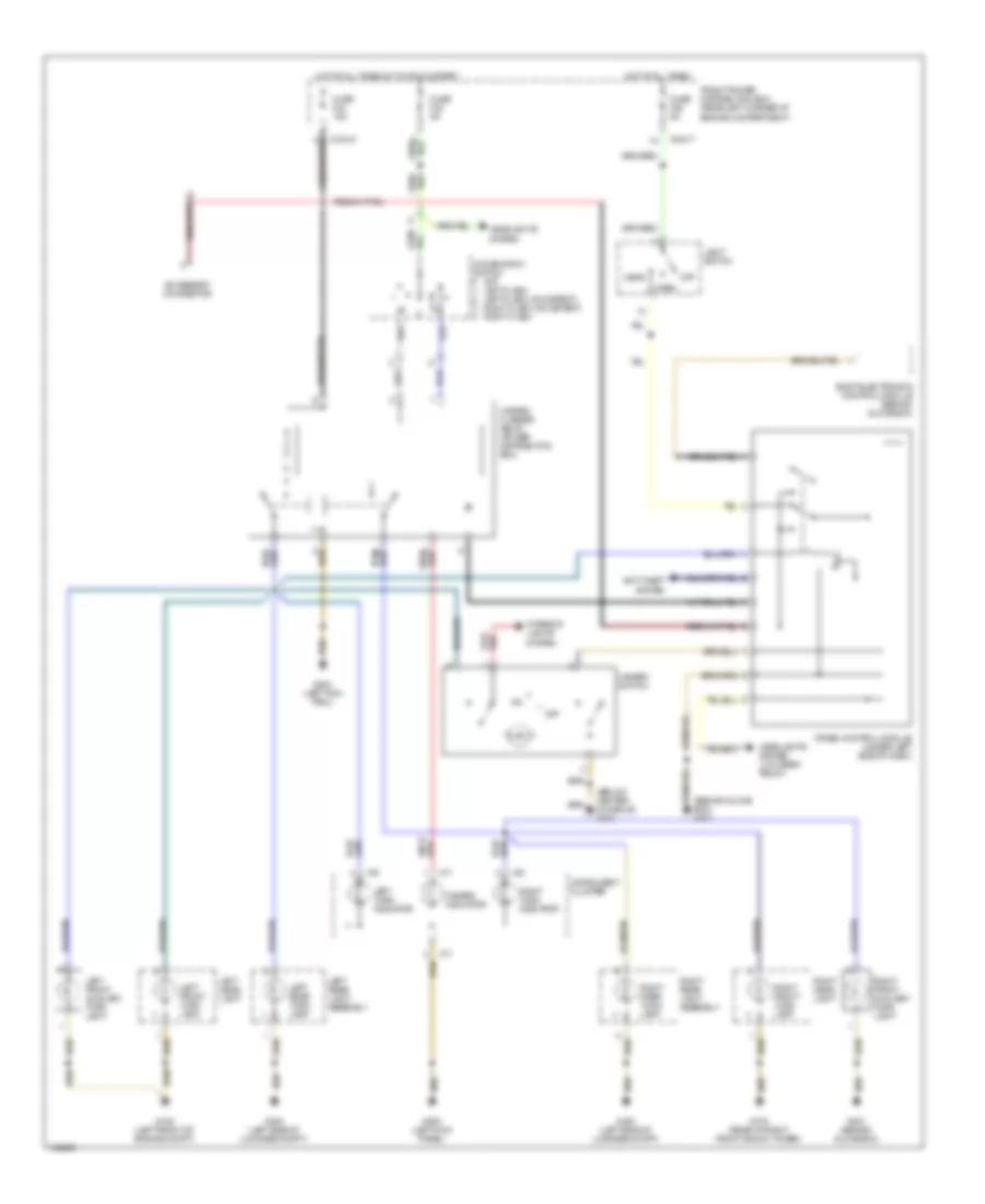
Turn & Hazard Lamps Wiring Diagram for BMW M Roadster 2000
 https://portal-diagnostov.com/license.html
Automotive Electricians Portal FZCO
Automotive Electricians Portal FZCO
https://portal-diagnostov.com/license.html
https://portal-diagnostov.com/license.html
Automotive Electricians Portal FZCO
Automotive Electricians Portal FZCOList of elements for Turn & Hazard Lamps Wiring Diagram for BMW M Roadster 2000:
- (behind glove box) g201
- (below center console) g302
- Accessory connector
- Anti-theft system
- Body electronics control module (behind glove box)
- Combination switch
- Crash control module (under left side of dash)
- Front power distribution box (rear left corner of engine compartment)
- Fuse f23 5a
- Fuse f25 5a
- Fuse f34 15a
- G103 (rear of right front shock tower)
- G108 (left front of engine compt)
- G200 (left kick panel)
- G200 (left kick panl)
- G201 (behind glove box)
- G400 (left side of luggage compt)
- Hazard flasher relay (power distribution box)
- Hazard indicator
- Hazard switch
- Head
- Headlights system
- Headlights system (low beam relay)
- Hot at all times
- Hot in run & start
- Instrument cluster
- Interior lights system
- Left front auxiliary turn light
- Left front turn lamp
- Left head- light
- Left rear light assembly
- Left rear turn lamp
- Left turn indicator
- Light switch
- Off
- Off left flash left flash (no detent) right flash (no detent) right flash
- Park
- Right front auxiliary turn light
- Right front turn lamp
- Right head- light
- Right rear light assembly
- Right rear turn lamp
- Right turn indicator
- X10017
- X10018
- X16
- X17
GROUND DISTRIBUTION
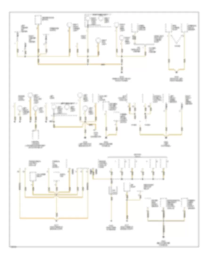
Ground Distribution Wiring Diagram (1 of 3) for BMW M Roadster 2000
 https://portal-diagnostov.com/license.html
Automotive Electricians Portal FZCO
Automotive Electricians Portal FZCO
https://portal-diagnostov.com/license.html
https://portal-diagnostov.com/license.html
Automotive Electricians Portal FZCO
Automotive Electricians Portal FZCOList of elements for Ground Distribution Wiring Diagram (1 of 3) for BMW M Roadster 2000:
- Air pump
- Auxiliary fan motor
- Central locking luggage compartment lid motor relay
- Data link connector
- Driver side impact sensor
- Driver's power window switch
- Dynamic stability control unit
- E-box fan
- Engine control module (dme)
- Engine hood switch
- G100 (front of left front fender)
- G103 (rear of right front shock tower)
- G108 (left front of engine compt)
- G117 (right rear of engine compt)
- G120 (right side of engine)
- G200 (left kick panel)
- G302 (below center console)
- Headlight/ foglight washer pump
- Ignition coils
- Left fog light
- Left front auxiliary turn light
- Left front marker light
- Left front speed sensor
- Left front turn light
- Left headlight
- Left high beam light
- Left horn
- Left low beam light
- Left park- light
- Left washer jet heater
- Nca
- Ohm
- Passen- ger's power window switch
- Passen- ger's side impact sensor
- Pre- charge pump
- Pressure switch
- Right fog light
- Right front abs speed sensor
- Right front marker light
- Right front turn light
- Right head- light
- Right headlight
- Right high beam light
- Right horn
- Right low beam light
- Right washer jet heater
- Secondary air pump relay
- Slip control module
- Steering angle sensor
- Temperature switch
- Thermal oil level switch
- Transmission control module
- Unloader relay
- W/ asc
- W/ dsc
- W/ head- light washer
- W/o headlight washer
- Wiper/ washer module
- X60001
- X60005
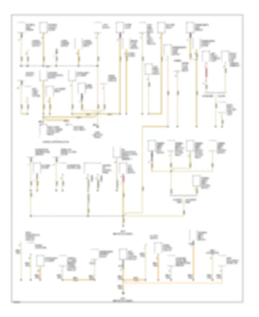
Ground Distribution Wiring Diagram (2 of 3) for BMW M Roadster 2000
 https://portal-diagnostov.com/license.html
Automotive Electricians Portal FZCO
Automotive Electricians Portal FZCO
https://portal-diagnostov.com/license.html
https://portal-diagnostov.com/license.html
Automotive Electricians Portal FZCO
Automotive Electricians Portal FZCOList of elements for Ground Distribution Wiring Diagram (2 of 3) for BMW M Roadster 2000:
- (w/ asc)
- (w/ dsc)
- Air conditioning recirculating switch assembly
- Anti- theft control module
- Anti- theft horn (alpine)
- Blower motor
- Blower relay
- Board computer
- Body electronics control module
- Brake fluid level relay
- Brake fluid level switch
- Canada late production
- Clutch switch
- Coupe
- Crash control module
- Driver's seat belt switch
- Driver's side mirror
- Driver's window motor
- Evaporator controller
- Evaporator temperature sensor
- Fresh air recirculation motor
- Front dome light/ map reading assembly
- G200 (left kick panel)
- G201 (behind glove box)
- Hazard flasher relay
- Heating/ a/c control panel
- High beam light relay or day- light relay module
- Ignition switch
- Instrument cluster
- Left front interior light
- Left park light relay
- Light switch
- Low beam light relay
- Mirror control switch
- Nca
- Obd ii connector
- On-board computer temperature sensor
- Passen- ger's seat control switch
- Passen- ger's seat length adjust cut-off relay
- Passen- ger's seat limit switch
- Passen- ger's seat tilt adjust cut-off relay
- Passenger's door jamb switch
- Passenger's seatbelt switch
- Passenger's side mirror
- Passenger's window motor
- Red
- Right front auxiliary turn light
- Right park light/license plate light relay
- Roadster
- Seat occupancy detector
- Starter immobilization switch
- Thermal oil level sensor (toens) control module
- Tilt sun roof switch
- Unloader relay
- W/ dsc
- W/ sport seat
- W/o sport seat
- Water valve
- Wiper motor
- Wiper/ washer module
- Wiper/ washer switch
- X18983
- X18984
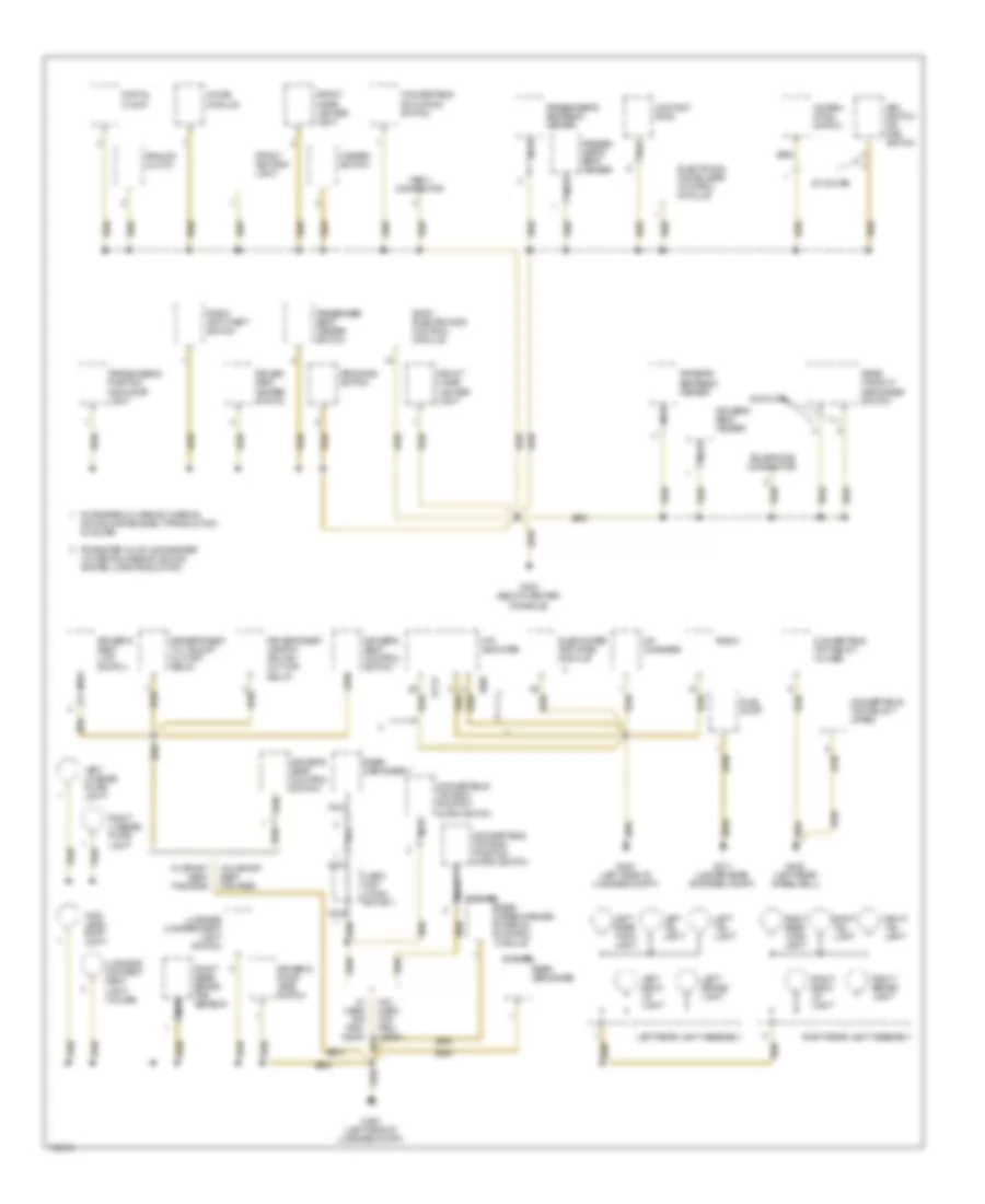
Ground Distribution Wiring Diagram (3 of 3) for BMW M Roadster 2000
 https://portal-diagnostov.com/license.html
Automotive Electricians Portal FZCO
Automotive Electricians Portal FZCO
https://portal-diagnostov.com/license.html
https://portal-diagnostov.com/license.html
Automotive Electricians Portal FZCO
Automotive Electricians Portal FZCOList of elements for Ground Distribution Wiring Diagram (3 of 3) for BMW M Roadster 2000:
- (coupe)
- Analog clock
- Asc switch or dsc switch
- Body electronics control module
- Cd changer
- Chime module
- Combin- ation switch
- Contact ring
- Convertible actuating switch
- Convertible top end- position micro switch
- Convertible top relay i (close)
- Convertible top relay ll (open)
- Digital clock
- Driver seat heater switch
- Driver's door jamb switch
- Driver's seat control switch
- Driver's seat heater
- Driver's seat length adjust cut-off relay
- Driver's seat limit switch
- Driver's seat tilt adjust cut-off relay
- Driver's seatback heater
- Electronic immobilizer control module
- Front ashtray light
- Front cigar lighter light
- Fuel pump
- G302 (below center console)
- G311 (under rear storage compt)
- G400 (left side of luggage compt)
- G402 (left rear wheelwell)
- G404 (left side of luggage compt)
- Hard top conn- ector 1
- Hazard switch
- Hifi amplifier
- High level stop light
- Left back- up light
- Left brake light
- Left license plate light
- Left rear light assembly
- Left rear turn light
- Left tail light
- Luggage compart- ment light (coupe)
- Luggage compartment light switch
- Nca
- Obd ii connector
- Passen- ger's seat heater
- Passenger seat heater switch
- Passenger's seatback heater
- Program switch
- Radio
- Radio anti-theft switch
- Rear defogger
- Rear defogger 1
- Rear window defogger switch
- Rear wiper/washer interval control module
- Right back- up light
- Right brake light
- Right license plate light
- Right rear brake pad sensor
- Right rear light assembly
- Right rear turn light
- Right tail light
- Roadster w/ harmon kardon sound system early production & coupe
- Roadster w/ hifi & roadster w/ harmon kardon sound system late production
- Subwoofer amplifier module
- Telephone connector
- Transmission position indicator light
- W/ hard top pro- vision
- W/ sport seat package
- W/o sport seat package
- X1717
- X605
- Z3 coupe
HEADLIGHTS
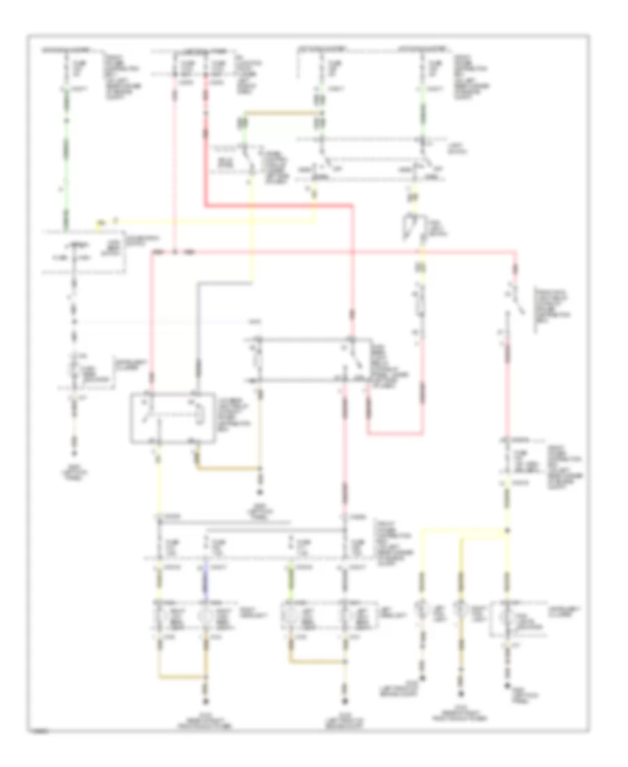
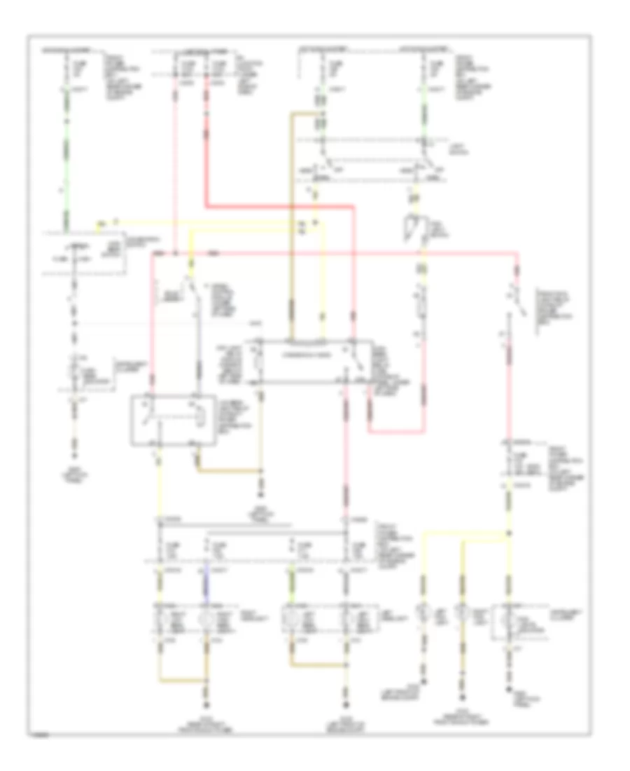
Headlights Wiring Diagram, Canada Late Production for BMW M Roadster 2000
 https://portal-diagnostov.com/license.html
Automotive Electricians Portal FZCO
Automotive Electricians Portal FZCO
https://portal-diagnostov.com/license.html
https://portal-diagnostov.com/license.html
Automotive Electricians Portal FZCO
Automotive Electricians Portal FZCOList of elements for Headlights Wiring Diagram, Canada Late Production for BMW M Roadster 2000:
- (2000) (2001)
- 87b
- B+ junction point (under left side of dash)
- Combination switch
- Crash control module (under left side of dash)
- Flash
- Fog- light switch
- Fog- lights indicator
- Front fog- light relay (in front power distribution box)
- Front power distribution box (on left rear corner of engine compt)
- Fuse f103 80a
- Fuse f104 80a
- Fuse f11 7.5a
- Fuse f12 7.5a
- Fuse f15 10a 15a
- Fuse f22 5a
- Fuse f23 5a
- Fuse f25 5a
- Fuse f29 7.5a
- Fuse f30 7.5a
- G103 (rear of right front shock tower)
- G108 (left front of engine compt)
- G200 (left kick panel)
- Head
- High
- High beam indicator
- High beam light relay (on relay panel, under left side of dash)
- High beam switch
- Hot at all times
- Hot in run & start
- Instrument cluster
- Left fog- light
- Left headlight
- Left high beam light
- Left low beam light
- Light switch
- Low beam light relay (in front power distribution box)
- Normal
- Off
- Park
- Red
- Right fog- light
- Right headlight
- Right high beam light
- Right low beam light
- Solid state
- X10016
- X10017
- X10035
- X10036
- X130
- X131
- X134
- X135
- X16
- X17
- X1978
- X1979
Headlights Wiring Diagram, USA & Canada Early Production for BMW M Roadster 2000
 https://portal-diagnostov.com/license.html
Automotive Electricians Portal FZCO
Automotive Electricians Portal FZCO
https://portal-diagnostov.com/license.html
https://portal-diagnostov.com/license.html
Automotive Electricians Portal FZCO
Automotive Electricians Portal FZCOList of elements for Headlights Wiring Diagram, USA & Canada Early Production for BMW M Roadster 2000:
- (2000) (2001)
- (canada only-2000)
- 87b
- B+ junction point (under left side of dash)
- Combination switch
- Crash control module (under left side of dash)
- Day light relay module (canada) (below left side of dash)
- Flash
- Fog- light switch
- Fog- lights indicator
- Front fog- light relay (in front power distribution box)
- Front power distribution box (on left rear corner of engine compt)
- Fuse f103 80a
- Fuse f104 80a
- Fuse f11 7.5a
- Fuse f12 7.5a
- Fuse f15 10a 15a
- Fuse f22 5a
- Fuse f23 5a
- Fuse f25 5a
- Fuse f29 7.5a
- Fuse f30 7.5a
- G103 (rear of right front shock tower)
- G108 (left front of engine compt)
- G200 (left kick panel)
- Head
- High
- High beam indicator
- High beam light relay (usa) (on relay panel, under left side of dash)
- High beam switch
- Hot at all times
- Hot in run & start
- Instrument cluster
- Left fog- light
- Left headlight
- Left high beam light
- Left low beam light
- Light switch
- Low beam light relay (in front power distribution box)
- Normal
- Off
- Park
- Red
- Right fog- light
- Right headlight
- Right high beam light
- Right low beam light
- Solid state
- X10016
- X10017
- X10035
- X10036
- X130
- X131
- X134
- X135
- X16
- X17
- X1978
- X1979
HORN
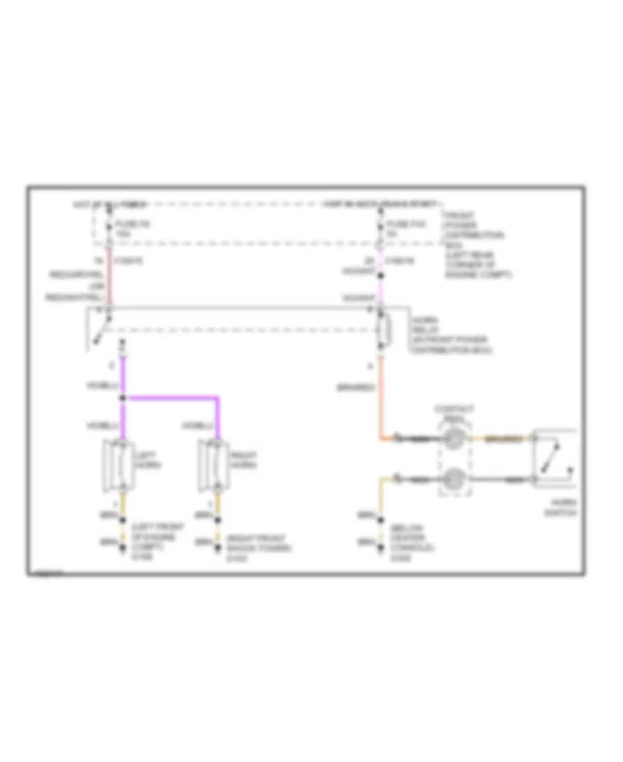
Horn Wiring Diagram for BMW M Roadster 2000
 https://portal-diagnostov.com/license.html
Automotive Electricians Portal FZCO
Automotive Electricians Portal FZCO
https://portal-diagnostov.com/license.html
https://portal-diagnostov.com/license.html
Automotive Electricians Portal FZCO
Automotive Electricians Portal FZCOList of elements for Horn Wiring Diagram for BMW M Roadster 2000:
- (below center console) g302
- (left front of engine compt) g108
- (or
- (right front shock tower) g103
- Contact ring
- Front power distribution box (left rear corner of engine compt)
- Fuse f43 5a
- Fuse f8 15a
- Horn relay (in front power distribution box)
- Horn switch
- Hot at all times
- Hot in accy, run & start
- Left horn
- Nca
- Right horn
- X10015
- X18018
INSTRUMENT CLUSTER
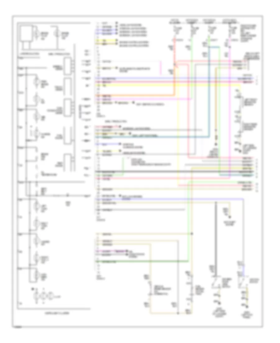
Instrument Cluster Wiring Diagram (1 of 2) for BMW M Roadster 2000
 https://portal-diagnostov.com/license.html
Automotive Electricians Portal FZCO
Automotive Electricians Portal FZCO
https://portal-diagnostov.com/license.html
https://portal-diagnostov.com/license.html
Automotive Electricians Portal FZCO
Automotive Electricians Portal FZCOList of elements for Instrument Cluster Wiring Diagram (1 of 2) for BMW M Roadster 2000:
- (behind glove box)
- (below left side of dash) chime module
- (left kick panel)
- (left side of luggage compt) g400
- A14
- A17
- A18
- A19
- A22
- A23
- A24
- Abs ind
- Air conditioning system
- Anti-lock brakes system
- Anti-theft system
- B14
- B15
- B16
- B19
- B21
- B22
- B23
- B25
- Brake fluid
- Brake fluid ind
- Brake pad ind
- Charge ind
- Data link connector (right rear side of engine compt)
- Drivers door jamb switch
- Early production
- Engine controls system
- Exterior lights system
- Front fog lt ind
- Front power distribution box (on left rear corner of engine compt)
- Fuel consumption meter
- Fuel gauge
- Fuel sensor (in fuel tank)
- Fuse f23 5a
- Fuse f27 5a
- Fuse f31 5a
- Fuse f46 15a
- G200
- G200 (left kick panel)
- G201
- G302 (below center console)
- G400 (left side of luggage compt)
- Hazard ind
- Headlights system
- High beam ind
- Hot at all times
- Hot in accy, run & start
- Hot in run & start
- Ignition switch
- Illum
- Ind
- Instrument cluster
- Interior lights system
- Late production
- Left front brake pad sensor
- Left turn ind
- Nca
- Oil ind
- Oil temperature
- Park brake ind
- Right rear brake pad sensor
- Right turn ind
- Seat belt ind
- Solid state
- Speedo- meter
- Srs ind
- Starting/ charging system
- Tacho- meter
- Temp gauge
- Vehicle speed sensor (on diferential)
- X10017
- X10018
- X16 conn a
- X17 conn b
- X271 conn c
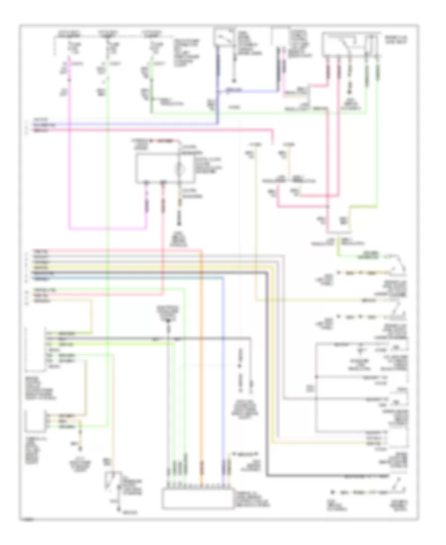
Instrument Cluster Wiring Diagram (2 of 2) for BMW M Roadster 2000
 https://portal-diagnostov.com/license.html
Automotive Electricians Portal FZCO
Automotive Electricians Portal FZCO
https://portal-diagnostov.com/license.html
https://portal-diagnostov.com/license.html
Automotive Electricians Portal FZCO
Automotive Electricians Portal FZCOList of elements for Instrument Cluster Wiring Diagram (2 of 2) for BMW M Roadster 2000:
- (coupe)
- (roadster)
- Bat
- Board computer (behind center console)
- Brake fluid level relay
- Brake fluid level switch (on top of master cylinder)
- Data link connector (right rear side of engine compt)
- Digital clock (coupe) analog clock (roadster)
- Driver's seatbelt switch
- Dynamic stability control unit (dsc) (on left side of eng compt)
- Early production
- Electronic immobilizer control module
- Engine control module (on right rear side of engine compt, in "e" box)
- Front power distribution box (on left rear corner of engine compt)
- Fuse f21 5a
- Fuse f26 10a
- Fuse f45 7.5a
- G117 (right rear of engine compt)
- G200 (left kick panel)
- G201 (behind glove box)
- G302 (below center console)
- Ground
- Hifi amplifier (w/ harmon kardon sound system)
- Hot in accy, run & start
- Hot in run & start
- Ign
- Interior lights system
- Late production
- Nca
- Oil pressure switch (left side of engine)
- Park brake switch (at base of parking brake lever)
- Radio
- Roadster late production
- Thermal oil level sensor control module (behind glove box)
- Thermal oil level switch (on left side of engine compt)
- Vss
- W/ asc
- W/ dsc
- Wiper/washer module (behind glove box)
- X10017
- X10018
- X10245
- X10266
- X1717
- X1746
- X18126
- X285
- X60003
- X60004
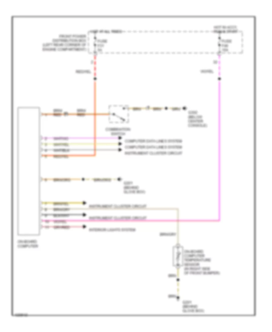
On-Board Computer Wiring Diagram for BMW M Roadster 2000
 https://portal-diagnostov.com/license.html
Automotive Electricians Portal FZCO
Automotive Electricians Portal FZCO
https://portal-diagnostov.com/license.html
https://portal-diagnostov.com/license.html
Automotive Electricians Portal FZCO
Automotive Electricians Portal FZCOList of elements for On-Board Computer Wiring Diagram for BMW M Roadster 2000:
- Combination switch
- Computer data lines system
- Front power distribution box (left rear corner of engine compartment)
- Fuse f31 5a
- Fuse f46 15a
- G201 (behind glove box)
- G302 (below center console)
- Hot at all times
- Hot in accy, run & start
- Instrument cluster circuit
- Interior lights system
- On-board computer
- On-board computer temperature sensor (in right side of front bumper)
INTERIOR LIGHTS
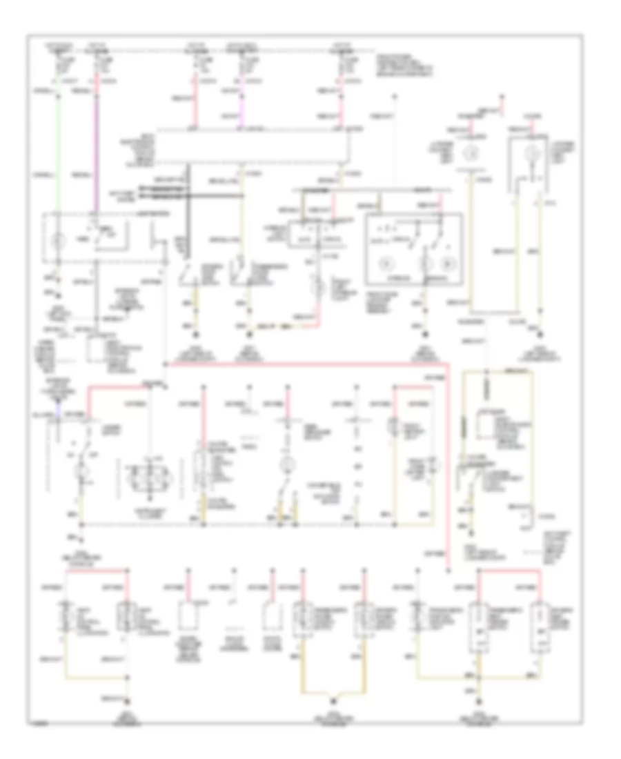
Interior Lights Wiring Diagram for BMW M Roadster 2000
 https://portal-diagnostov.com/license.html
Automotive Electricians Portal FZCO
Automotive Electricians Portal FZCO
https://portal-diagnostov.com/license.html
https://portal-diagnostov.com/license.html
Automotive Electricians Portal FZCO
Automotive Electricians Portal FZCOList of elements for Interior Lights Wiring Diagram for BMW M Roadster 2000:
- (coupe)
- (roadster)
- Analog clock (roadster)
- Anti-theft control module (behind glove box)
- Anti-theft system
- Asc switch or dsc switch
- Auto
- Board computer (behind center console)
- Body electronics control module (behind glove box)
- Convertible top actuating switch
- Coupe
- Digital clock (coupe)
- Driver's door jamb switch
- Driver's power window switch
- Driver's seat heater switch
- Exterior lights (license plate lights)
- Exterior lights (turn/hazard lights)
- Front ashtray light
- Front cigar lighter light
- Front dome light/map reading assembly
- Front left interior light
- Front power distribution box (left rear corner of engine compartment)
- Fuse f2 10a
- Fuse f23 5a
- Fuse f33 10a
- Fuse f37 10a
- Fuse f43 5a
- G200 (left kick panel)
- G201 (behind glove box)
- G302 (below center console)
- G400 (left side of luggage compt)
- Hazard switch
- Head
- Heat/ a/c control panel illumination
- Hot at all times
- Hot in accy, run & start
- Hot in run & start
- Instrument cluster
- Interior
- Interior light switch
- Light switch
- Luggage compart- ment light
- Luggage compartment light switch
- Manual
- Nca
- Off
- Park
- Passenger's door jamb switch
- Passenger's power window switch
- Passenger's seat heater switch
- Radio
- Reading
- Rear defogger switch
- Roadster
- Transmission position indicator light
- Wiper/ washer module (behind glove box)
- X10015
- X10017
- X10018
- X10182
- X10245
- X11104
- X11105
- X11106
- X13025
- X13252
- X13254
- X16
- X18080
- X712
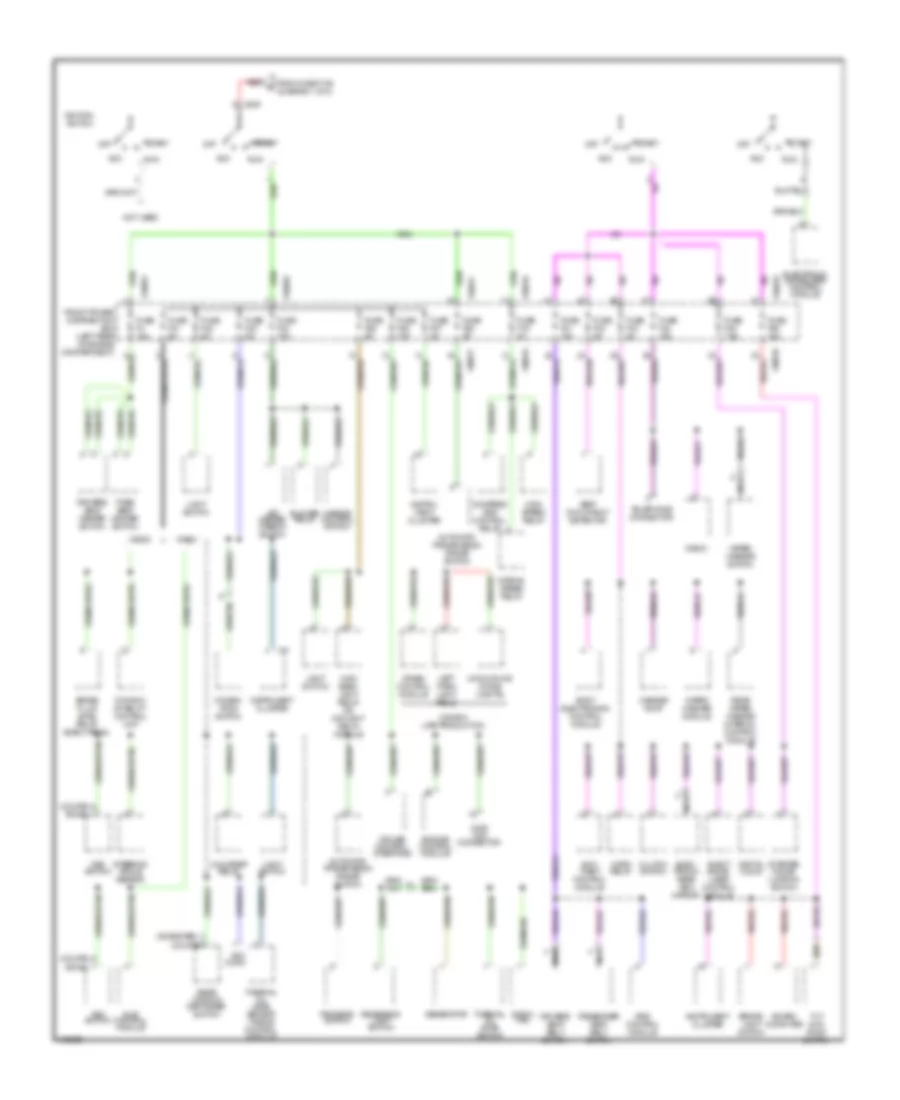
POWER DISTRIBUTION
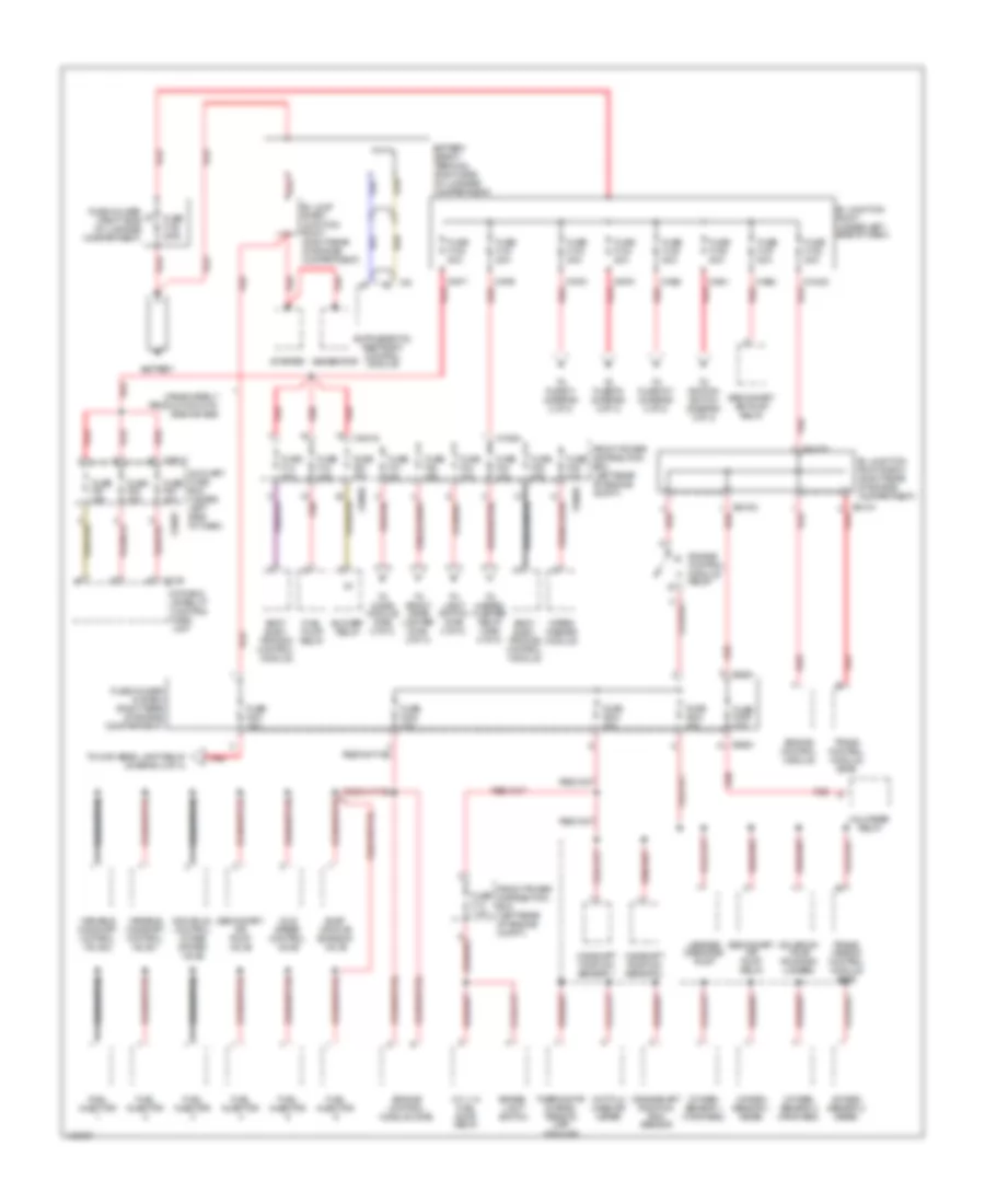
Power Distribution Wiring Diagram (1 of 3) for BMW M Roadster 2000
 https://portal-diagnostov.com/license.html
Automotive Electricians Portal FZCO
Automotive Electricians Portal FZCO
https://portal-diagnostov.com/license.html
https://portal-diagnostov.com/license.html
Automotive Electricians Portal FZCO
Automotive Electricians Portal FZCOList of elements for Power Distribution Wiring Diagram (1 of 3) for BMW M Roadster 2000:
- Auxiliary fuse box (under left side of dash)
- B+ jump start junction point (right rear of engine compartment)
- B+ junction point (under left side of dash)
- B+ junction point e-box (right rear of engine compartment)
- Battery
- Battery safety terminal (right side of luggage compartment)
- Blower relay
- Body elec- tronics control module
- Brake- light switch
- Camshaft position sensor 1
- Camshaft position sensor 2
- Canada early production with side air bag
- Crankshaft position/ rpm sensor
- Cyl 1-6 fuel pump relay
- Dynamic stability control (dsc) unit
- Engine control module
- Engine control module (dme)
- Engine control module relay
- Evap- orative emission valve
- Front power distribution box (left rear of engine compt)
- Fuel injector
- Fuel pump relay
- Fuse f100 200a
- Fuse f101 80a
- Fuse f102 80a
- Fuse f103 80a
- Fuse f104 80a
- Fuse f105 80a
- Fuse f106 50a
- Fuse f107 50a
- Fuse f108 80a
- Fuse f13 7.5a
- Fuse f14 30a
- Fuse f18 15a
- Fuse f20 30a
- Fuse f201 15a
- Fuse f202 30a
- Fuse f203 20a
- Fuse f204 30a
- Fuse f205 30a
- Fuse f31 5a
- Fuse f32 30a
- Fuse f33 10a
- Fuse f34 15a
- Fuse f35 25a
- Fuse f36 30a
- Fuse f51 30a
- Fuse f52 30a
- Fuse f53 30a
- Fuse holder (right side of luggage compartment)
- Fuse holder in e-box (right rear of engine compartment)
- Generator
- Hot film mass air meter
- Idle speed control valve
- Individual control intake system valve
- Leakage diagnosis pump
- Oxygen sensor 1 (forward)
- Oxygen sensor 1 (rear)
- Oxygen sensor 2 (forward)
- Oxygen sensor 2 (rear)
- Red
- Red x8680
- Secondary air pump relay
- Secondary air pump valve
- Solenoid valve (running losses)
- Starter
- Thermostat charac- teristic map cooling
- To chime module (diag 2 of 3)
- To front cigar lighter (diag 2 of 3)
- To fuse f1 (diagram 2 of 3)
- To fuse f37 (diagram 2 of 3)
- To fuse f5 (diagram 2 of 3)
- To hazard flasher relay (diag 2 of 3)
- To high beam light relay (diagram 2 of 3)
- To ignition switch (diagram 3 of 3)
- To light switch (diag 2 of 3)
- Trans control module (egs)
- Trans- mission control module (egs)
- Unloader relay
- Variable camshaft control valve 1
- Variable camshaft control valve 2
- Wiper/ washer module
- X10016
- X10018
- X10034
- X10422
- X1746
- X19017
- X1976
- X1977
- X1978
- X1979
- X1980
- X1981
- X1982
- X64101 red
- X64102 red
- X64192
- X74
- X8680
Power Distribution Wiring Diagram (2 of 3) for BMW M Roadster 2000
 https://portal-diagnostov.com/license.html
Automotive Electricians Portal FZCO
Automotive Electricians Portal FZCO
https://portal-diagnostov.com/license.html
https://portal-diagnostov.com/license.html
Automotive Electricians Portal FZCO
Automotive Electricians Portal FZCOList of elements for Power Distribution Wiring Diagram (2 of 3) for BMW M Roadster 2000:
- (coupe)
- A red
- Accessory conn
- All others red
- Analog clock
- Anti- theft control module
- B red
- Board computer
- Body elec- tronics control module
- Body electronics control module
- C red
- Canada early production with side air bag
- Canada late prod
- Cd changer
- Chime module
- Compressor control relay
- Conv top relay
- Coupe
- Crash control module
- Data link con- nec- tor
- Digital clock
- Drivers door lock motor
- Drivers door lock switch
- Drivers seat control switch
- Elec- tronic immob- ilizer control module
- From fuse f103 (diagram 1 of 3)
- From fuse f104 (diagram 1 of 3)
- From fuse f105 (diagram 1 of 3)
- From fuse f201 (diagram 1 of 3)
- From fuse f31 (diagram 1 of 3)
- From fuse f32 (diagram 1 of 3)
- From fuse f33 (diagram 1 of 3)
- From fuse f34 (diagram 1 of 3)
- Front cigar lighter
- Front dome light/ map reading assembly (coupe)
- Front fog light relay
- Front power distribution box (left rear of engine compartment)
- Fuse f1 30a
- Fuse f10 30a
- Fuse f11 7.5a
- Fuse f12 7.5a
- Fuse f15 10a
- Fuse f19 30a
- Fuse f2 10a
- Fuse f29 7.5a
- Fuse f3 30a
- Fuse f30 7.5a
- Fuse f37 10a
- Fuse f38 30a
- Fuse f39 7.5a
- Fuse f40 30a
- Fuse f5 30a
- Fuse f6 20a
- Fuse f7 5a
- Fuse f8 15a
- Fuse f9 20a
- G302 (below center console)
- Hazard flasher relay
- Hifi amplifier
- High beam light relay or day light relay module
- High speed relay
- Horn relay
- Instru- ment cluster
- Instrument cluster
- Interior light switch (roadster)
- Kardon sound system early production & all coupe
- Left fog- light
- Left head- light
- Left park light relay (canada late production)
- Light switch
- Low beam light relay
- Luggage compartment light
- Luggage compartment lock motor
- Nca
- Obd ii con- nector
- Passenger's door lock motor
- Passenger's door lock switch
- Passenger's seat control switch
- Radio
- Rear wiper/ washer interval control module
- Red
- Right fog- light
- Right head- light
- Right park light/license plate light relay
- Roadster
- Roadster w/ harmon kardon sound system late production
- Roadster w/ harmon-
- Slip control module
- Steering angle sensor
- Subwoofer amplifier module
- Tele- phone conn
- Thermal oil level sensor (toens) control module
- Unloader relay
- Wiper/ washer module
- X10015
- X10016
- X10017
- X10018
- X10030
- X10035
- X10036
- X10038
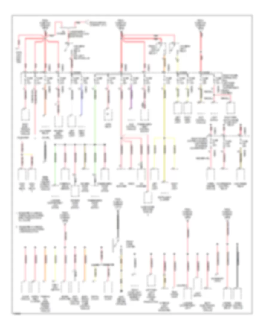
Power Distribution Wiring Diagram (3 of 3) for BMW M Roadster 2000
 https://portal-diagnostov.com/license.html
Automotive Electricians Portal FZCO
Automotive Electricians Portal FZCO
https://portal-diagnostov.com/license.html
https://portal-diagnostov.com/license.html
Automotive Electricians Portal FZCO
Automotive Electricians Portal FZCOList of elements for Power Distribution Wiring Diagram (3 of 3) for BMW M Roadster 2000:
- (coupe) (road)
- (roadster) (coupe)
- Acc
- Acc conn
- Anti- theft control module
- Asc switch
- Automatic transmission range switch
- Blower relay
- Board computer
- Body electronics control module
- Brake fluid level relay (early prod)
- Brake- light switch
- Canada late production
- Clutch switch
- Combin- ation switch
- Compres- sor control relay
- Crash control module
- Cruise control interface
- Data link connector
- Digital clock
- Drivers seat belt switch
- Drivers seat heater switch
- Dsc switch
- Dynamic stability control unit
- E-box fan
- Elec- tronic rear view mirror
- Elect immob- ilizer control module
- Electronic immobilizer control module
- Engine control module
- From fuse f106 (diagram 1 of 3)
- Front power distribution box (left rear of engine compartment)
- Fuse f16 5a
- Fuse f21 5a
- Fuse f22 5a
- Fuse f23 5a
- Fuse f24 10a
- Fuse f25 5a
- Fuse f26 10a
- Fuse f27 5a
- Fuse f28 5a
- Fuse f4 15a
- Fuse f41 15a
- Fuse f42 5a
- Fuse f43 5a
- Fuse f44 15a
- Fuse f45 7.5a
- Fuse f46 15a
- Generator
- High beam light relay or daylight relay module
- High speed relay
- Horn relay
- Ignition switch
- Instru- ment cluster
- Instrument cluster
- Jet heater thermo switch
- Left park light relay
- Light switch
- Mirror control switch
- Nca
- Normal speed relay
- Not used
- Off
- Pass seat heater switch
- Passenger seat belt switch
- Program switch
- Radio
- Rear window defogger switch
- Rear wiper/ washer interval control module
- Red
- Reversing light switch
- Run
- Seat occupancy detector
- Slip control module
- Srs control module
- Start
- Starter immob- ilization switch
- Steering angle sensor
- Telephone connector
- Thermal oil level sensor (toens) control module
- Thermal oil level switch
- Tilt sun roof switch
- Uncoupling diode (lights)
- Unloader relay
- W/asc
- W/dsc
- Washer pump
- Wiper/ washer module
- Wiper/ washer switch
- X10015
- X10016
- X10017
- X10018
- X10026
- X17
- X209
POWER DOOR LOCKS
Power Door Locks Wiring Diagram for BMW M Roadster 2000
 https://portal-diagnostov.com/license.html
Automotive Electricians Portal FZCO
Automotive Electricians Portal FZCO
https://portal-diagnostov.com/license.html
https://portal-diagnostov.com/license.html
Automotive Electricians Portal FZCO
Automotive Electricians Portal FZCOList of elements for Power Door Locks Wiring Diagram for BMW M Roadster 2000:
- (behind glove box) g201
- (below center console)
- (coupe)
- (roadster)
- Anti-theft control module (behind glove box)
- Anti-theft system (driver's door jamb switch)
- Anti-theft system (passenger's door jamb switch)
- Body electronics control module (behind glove box)
- Data link connector (rear of eng compartment)
- Driver's door lock motor
- Driver's door lock switch
- Electronic immobilizer control module (under left side of dash)
- Exterior lights system
- Front power distribution box (on left rear corner of engine compartment)
- Fuse f35 25a
- Fuse f43 5a
- Fuse f7 5a
- G302
- Gas filler lock motor
- Hot at all times
- Hot in accy, run & start
- Interior lights system
- Lock
- Nca
- Passenger's door lock motor
- Passenger's door lock switch
- Trunk lock motor (on rear side of luggage compt)
- Unlock
- X10015
- X10018
- X10182
- X13252
- X13253
- X13254
- X311
- X315
POWER MIRRORS
Power Mirrors Wiring Diagram for BMW M Roadster 2000
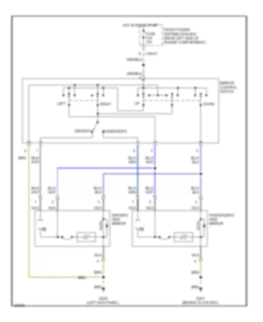 https://portal-diagnostov.com/license.html
Automotive Electricians Portal FZCO
Automotive Electricians Portal FZCO
https://portal-diagnostov.com/license.html
https://portal-diagnostov.com/license.html
Automotive Electricians Portal FZCO
Automotive Electricians Portal FZCOList of elements for Power Mirrors Wiring Diagram for BMW M Roadster 2000:
- Down
- Driver's
- Driver's side mirror
- Front power distribution box (rear left side of engine compartment)
- Fuse f24 10a
- G200 (left kick panel)
- G201 (behind glove box)
- Hot in run & start
- Left
- Mirror control switch
- Nca
- Passenger's
- Passenger's side mirror
- Right
- X10017
POWER SEATS
Driver"s Sport Seat Wiring Diagram for BMW M Roadster 2000
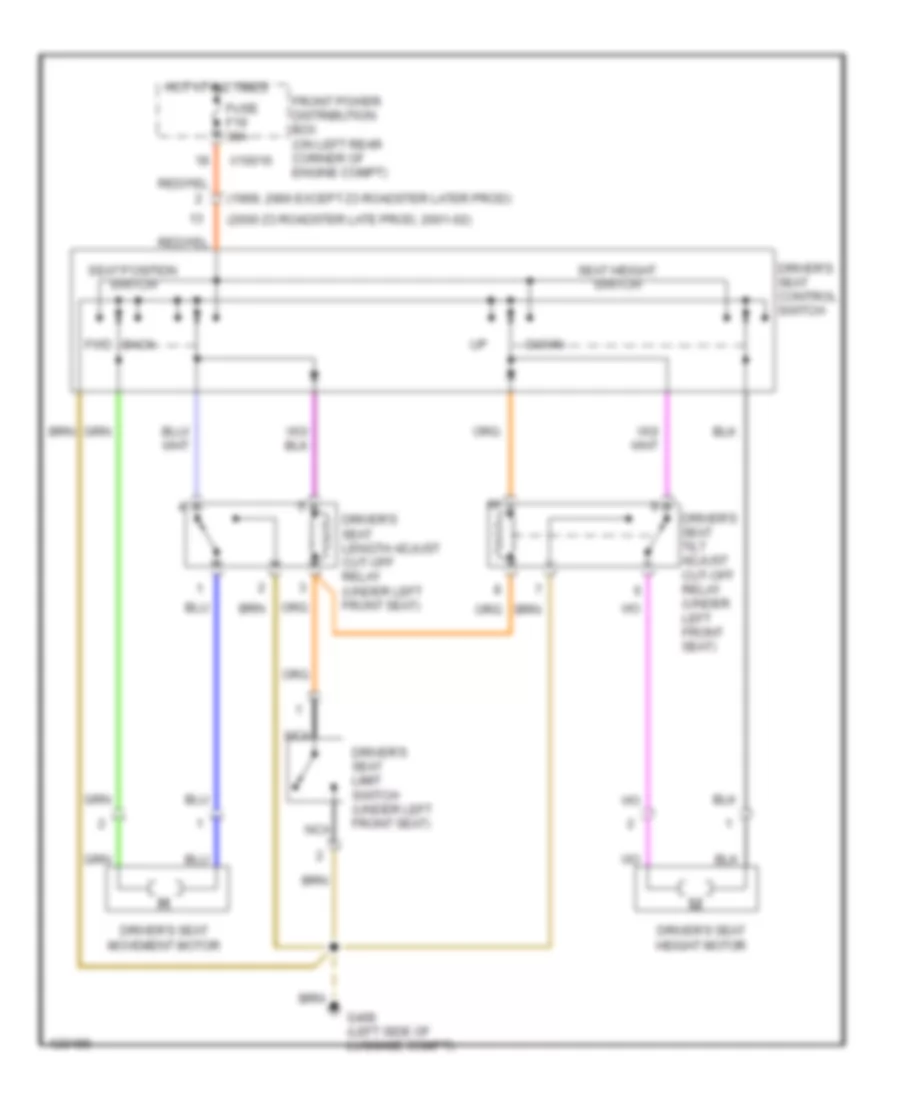 https://portal-diagnostov.com/license.html
Automotive Electricians Portal FZCO
Automotive Electricians Portal FZCO
https://portal-diagnostov.com/license.html
https://portal-diagnostov.com/license.html
Automotive Electricians Portal FZCO
Automotive Electricians Portal FZCOList of elements for Driver"s Sport Seat Wiring Diagram for BMW M Roadster 2000:
- (1999, 2000 except z3 roadster later prod)
- (2000 z3 roadster late prod, 2001-02)
- Back
- Down
- Driver's seat control switch
- Driver's seat height motor
- Driver's seat length adjust cut-off relay (under left front seat)
- Driver's seat limit switch (under left front seat)
- Driver's seat movement motor
- Driver's seat tilt adjust cut-off relay (under left front seat)
- Front power distribution box (on left rear corner of engine compt)
- Fuse f19 30a
- Fwd
- G400 (left side of luggage compt)
- Hot at all times
- Nca
- Seat height switch
- Seat position switch
- X10016
Heated Seats Wiring Diagram for BMW M Roadster 2000
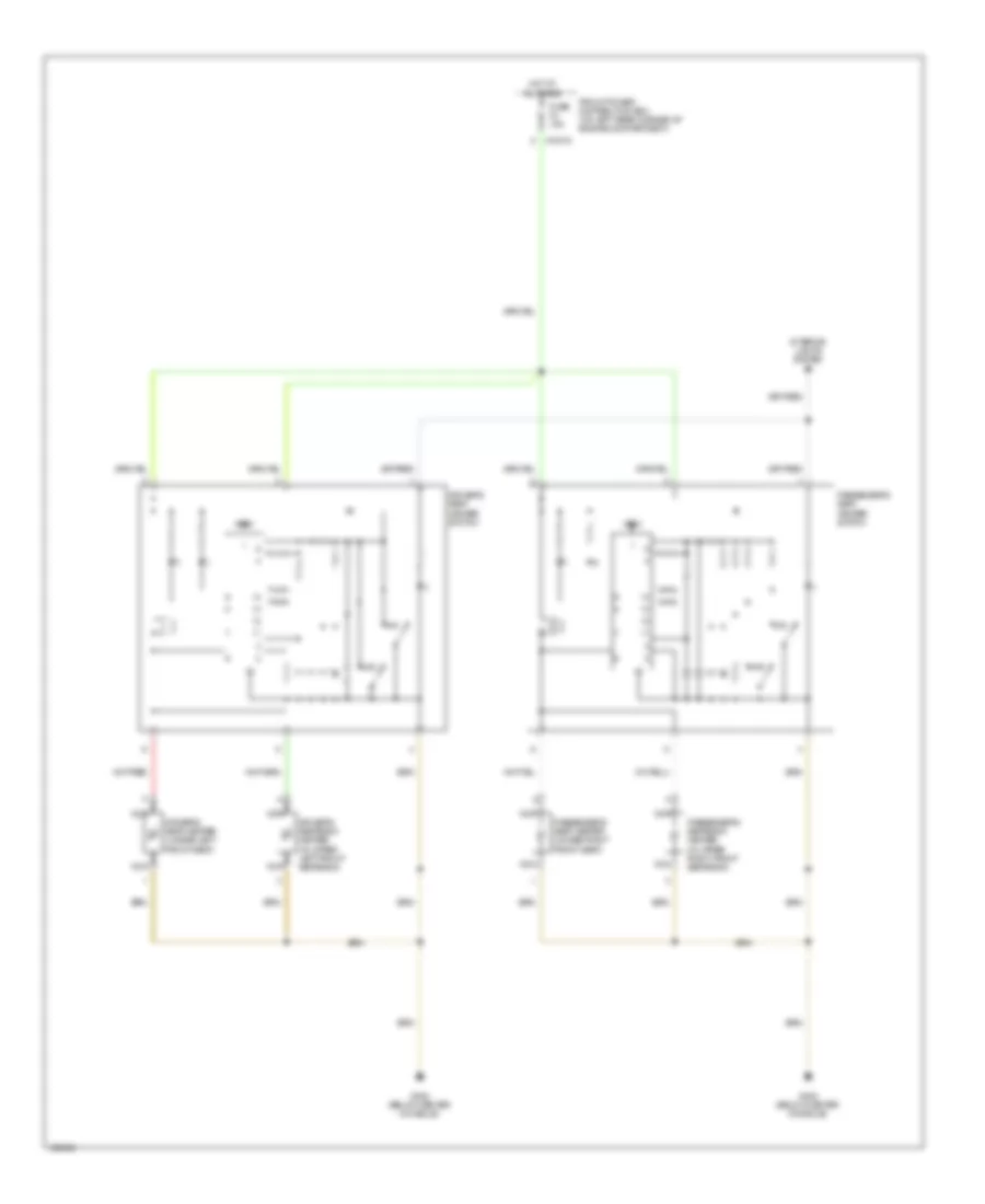 https://portal-diagnostov.com/license.html
Automotive Electricians Portal FZCO
Automotive Electricians Portal FZCO
https://portal-diagnostov.com/license.html
https://portal-diagnostov.com/license.html
Automotive Electricians Portal FZCO
Automotive Electricians Portal FZCOList of elements for Heated Seats Wiring Diagram for BMW M Roadster 2000:
- Driver's seat heater (under left front seat)
- Driver's seat heater switch
- Driver's seatback heater (in upper left front seatback)
- Front power distribution box (on left rear corner of engine compartment)
- Fuse f4 15a
- G302 (below center console)
- Hot at all times
- Interior lights system
- Max
- Min
- Nca
- Passenger's seat heater (under right front seat)
- Passenger's seat heater switch
- Passenger's seatback heater (in upper right front seatback)
- Test
- X10015
Passenger"s Sport Seat Wiring Diagram for BMW M Roadster 2000
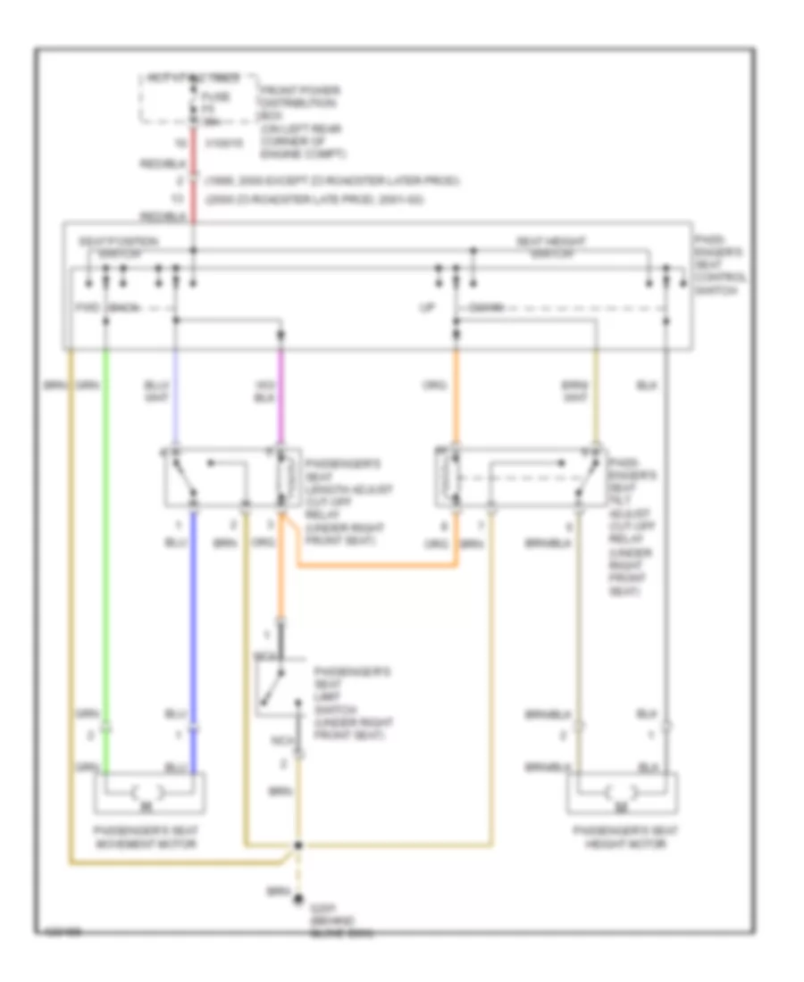 https://portal-diagnostov.com/license.html
Automotive Electricians Portal FZCO
Automotive Electricians Portal FZCO
https://portal-diagnostov.com/license.html
https://portal-diagnostov.com/license.html
Automotive Electricians Portal FZCO
Automotive Electricians Portal FZCOList of elements for Passenger"s Sport Seat Wiring Diagram for BMW M Roadster 2000:
- (1999, 2000 except z3 roadster later prod)
- (2000 z3 roadster late prod, 2001-02)
- Back
- Down
- Front power distribution box (on left rear corner of engine compt)
- Fuse f5 30a
- Fwd
- G201 (behind glove box)
- Hot at all times
- Nca
- Pass- enger's seat control switch
- Pass- enger's seat tilt adjust cut-off relay (under right front seat)
- Passenger's seat height motor
- Passenger's seat length adjust cut-off relay (under right front seat)
- Passenger's seat limit switch (under right front seat)
- Passenger's seat movement motor
- Seat height switch
- Seat position switch
- X10015
Power Seats Wiring Diagram for BMW M Roadster 2000
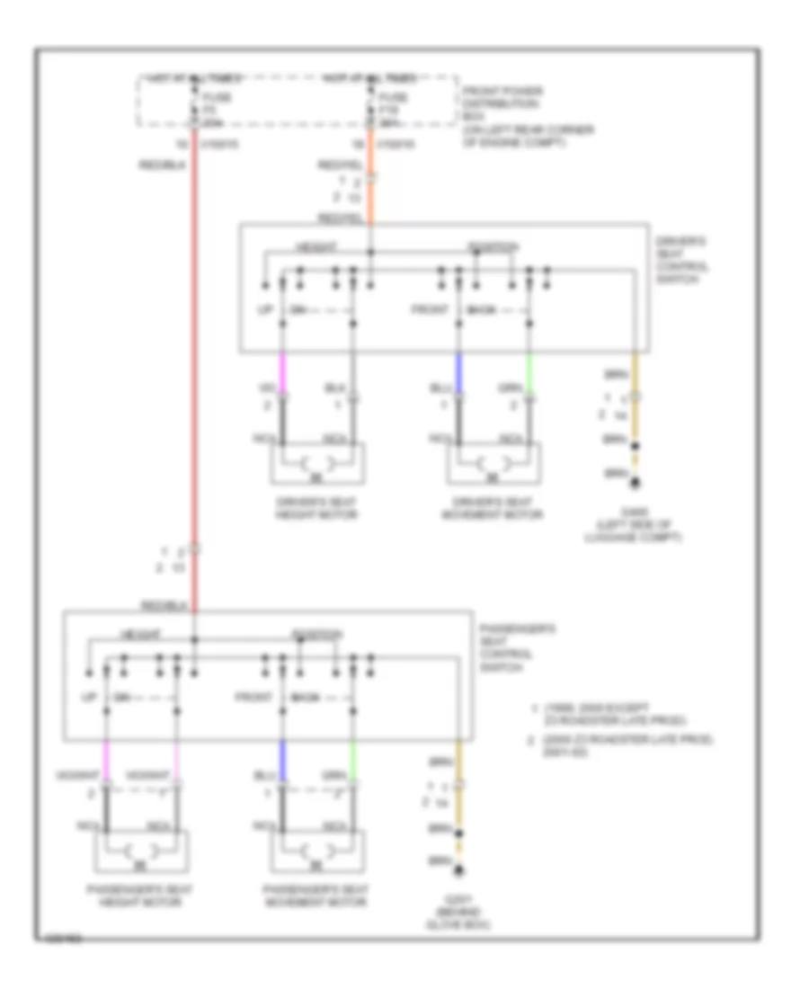 https://portal-diagnostov.com/license.html
Automotive Electricians Portal FZCO
Automotive Electricians Portal FZCO
https://portal-diagnostov.com/license.html
https://portal-diagnostov.com/license.html
Automotive Electricians Portal FZCO
Automotive Electricians Portal FZCOList of elements for Power Seats Wiring Diagram for BMW M Roadster 2000:
- (1999, 2000 except
- (2000 z3 roadster late prod,
- 2001-02)
- Back
- Driver's seat control switch
- Driver's seat height motor
- Driver's seat movement motor
- Front
- Front power distribution box (on left rear corner of engine compt)
- Fuse f19 30a
- Fuse f5 30a
- G201 (behind glove box)
- G400 (left side of luggage compt)
- Height
- Hot at all times
- Nca
- Passenger's seat control switch
- Passenger's seat height motor
- Passenger's seat movement motor
- Position
- X10015
- X10016
- Z3 roadster late prod)
POWER TOP/SUNROOF
Convertible Top Wiring Diagram for BMW M Roadster 2000
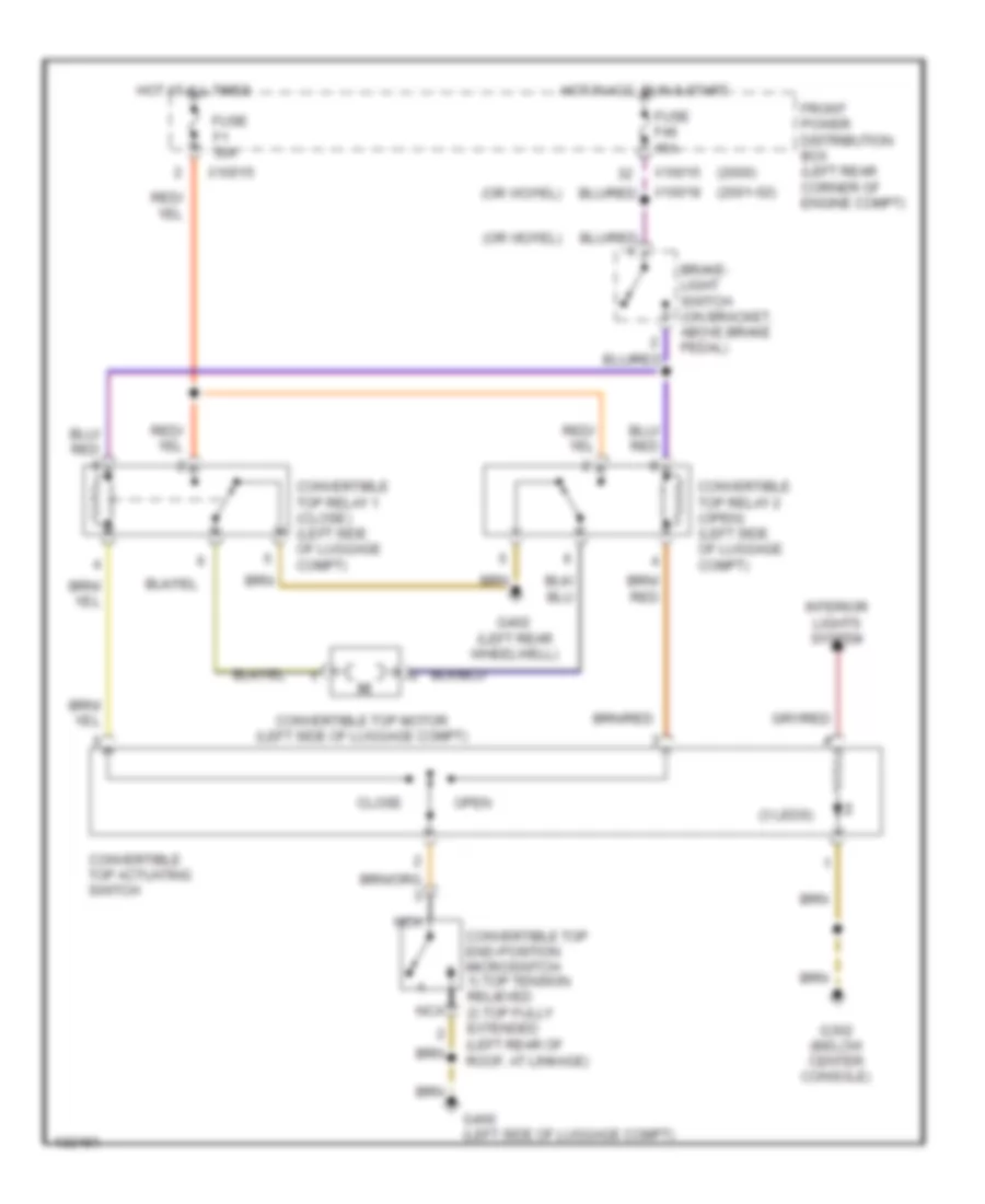 https://portal-diagnostov.com/license.html
Automotive Electricians Portal FZCO
Automotive Electricians Portal FZCO
https://portal-diagnostov.com/license.html
https://portal-diagnostov.com/license.html
Automotive Electricians Portal FZCO
Automotive Electricians Portal FZCOList of elements for Convertible Top Wiring Diagram for BMW M Roadster 2000:
- (2000)
- (2001-02)
- (3 leds)
- Brake- light switch (on bracket, above brake pedal)
- Close
- Convertible top actuating switch
- Convertible top end-position microswitch 1) top tension relieved 2) top fully extended (left rear of roof, at linkage)
- Convertible top motor (left side of luggage compt)
- Convertible top relay 1 (close) (left side of luggage compt)
- Convertible top relay 2 (open) (left side of luggage compt)
- Front power distribution box (left rear corner of engine compt)
- Fuse f1 30a
- Fuse f46 15a
- G302 (below center console)
- G400 (left side of luggage compt)
- G402 (left rear wheelwell)
- Hot at all times
- Hot in acc, run & start
- Interior lights system
- Nca
- Open
- X10015
- X10018
POWER WINDOWS
Power Windows Wiring Diagram for BMW M Roadster 2000
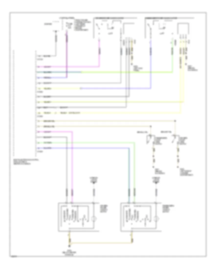 https://portal-diagnostov.com/license.html
Automotive Electricians Portal FZCO
Automotive Electricians Portal FZCO
https://portal-diagnostov.com/license.html
https://portal-diagnostov.com/license.html
Automotive Electricians Portal FZCO
Automotive Electricians Portal FZCOList of elements for Power Windows Wiring Diagram for BMW M Roadster 2000:
- Body electronics control module (zke iv) (behind glove box)
- Close auto
- Close wdo
- Drivers door jamb switch
- Drivers power window motor
- Drivers power window switch
- Front power distribution box (left rear corner of engine compartment)
- Fuse f14 30a
- G200 (left kick panel)
- G201 (behind glove box)
- G302 (below center console)
- G400 (left side of luggage compartment)
- Hot at all times
- Interior lights system
- Off
- Open auto
- Open wdo
- Passengers door jamb switch
- Passengers power window motor
- Passengers power window switch
- Starter
- X10182
- X13252
- X13253
- X13254
- X18279
- X18280
- X744
- X749
RADIO
Radio Wiring Diagram, Coupe & Early Production Roadster for BMW M Roadster 2000
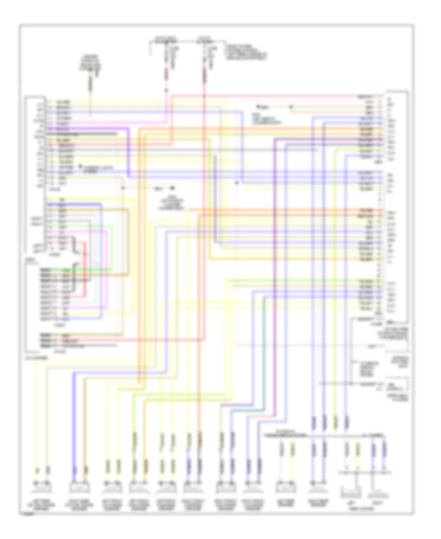 https://portal-diagnostov.com/license.html
Automotive Electricians Portal FZCO
Automotive Electricians Portal FZCO
https://portal-diagnostov.com/license.html
https://portal-diagnostov.com/license.html
Automotive Electricians Portal FZCO
Automotive Electricians Portal FZCOList of elements for Radio Wiring Diagram, Coupe & Early Production Roadster for BMW M Roadster 2000:
- (center console) telephone connector
- 58g
- All others
- Ant
- Antenna amplifier am/fm
- Cd changer
- Coupe w/o harman kardon system
- Front power distribution box (left rear corner of engine compartment)
- Fuse f44 15a
- Fuse f9 20a
- G404 (left side of luggage compartment)
- G404 (left side of luggage compt)
- Gal
- Hifi amplifier (on right side of luggage compt)
- Hl+
- Hl-
- Hlv+
- Hlv-
- Hot at all times
- Hot in accy, run & start
- Hr+
- Hr-
- Hrv+
- Hrv-
- I-bus
- Instrument cluster
- Interior lights system
- Left
- Left front high range speaker
- Left front low range speaker
- Left front midrange speaker
- Left rear mid-high range speaker
- Left rear speaker
- Left+
- Mlh+
- Mlh-
- Mlv+
- Mlv-
- Mrh+
- Mrh-
- Mrv+
- Mrv-
- Mute
- Nca
- Radio
- Rear woofer
- Red
- Right
- Right front high range speaker
- Right front low range speaker
- Right front midrange speaker
- Right rear mid-high range speaker
- Right rear speaker
- Right-
- Tlh+
- Tlh-
- Tlv+
- Tlv-
- Trh+
- Trh-
- Trv+
- Trv-
- Vl+
- Vl-
- Vr+
- Vr-
- Vss output
- W/ harman kardon sound system
- X10015
- X10018
- X10266
- X17
- X18126
- X18180
- X18520
- X18521
- X400
- X605
- X606
Radio Wiring Diagram, Roadster with Harman Kardon for BMW M Roadster 2000
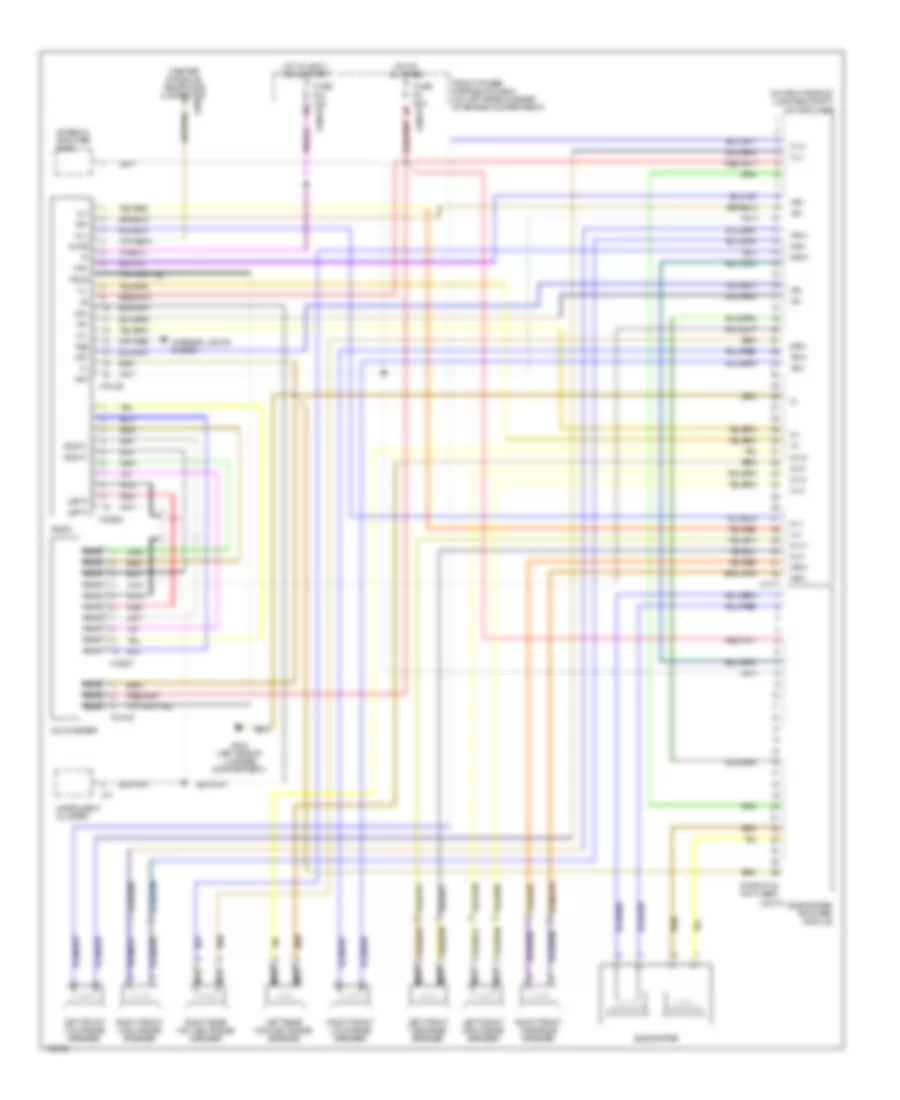 https://portal-diagnostov.com/license.html
Automotive Electricians Portal FZCO
Automotive Electricians Portal FZCO
https://portal-diagnostov.com/license.html
https://portal-diagnostov.com/license.html
Automotive Electricians Portal FZCO
Automotive Electricians Portal FZCOList of elements for Radio Wiring Diagram, Roadster with Harman Kardon for BMW M Roadster 2000:
- (center console) telephone connector
- (on right side of luggage compt) hifi amplifier
- (pins 27-42 not used)
- 58g
- Ant
- Antenna amplifier am/fm
- Cd changer
- Front power distribution box (on left rear corner of engine compartment)
- Fuse f44 15a
- Fuse f9 20a
- G404 (left side of luggage compartment)
- Gal
- Hl+
- Hl-
- Hlv+
- Hlv-
- Hot at all times
- Hot in accy, run & start
- Hr+
- Hr-
- Hrv+
- Hrv-
- I-bus
- Instrument cluster
- Interior lights system
- Left front high range speaker
- Left front low range speaker
- Left front midrange speaker
- Left rear mid-high range speaker
- Left+
- Mlh+
- Mlh-
- Mlv+
- Mlv-
- Mrh+
- Mrh-
- Mrv+
- Mrv-
- Mute
- Nca
- Radio
- Red
- Right front high range speaker
- Right front low range speaker
- Right front midrange speaker
- Right rear mid-high range speaker
- Right-
- Subwoofer
- Subwoofer amplifier module
- Tlv+
- Tlv-
- Trv+
- Trv-
- Vl+
- Vl-
- Vr+
- Vr-
- X10015
- X10018
- X17
- X1717
- X18126
- X18180
- X18520
- X18521
- X18774
- X400
Radio Wiring Diagram, Roadster without Harman Kardon for BMW M Roadster 2000
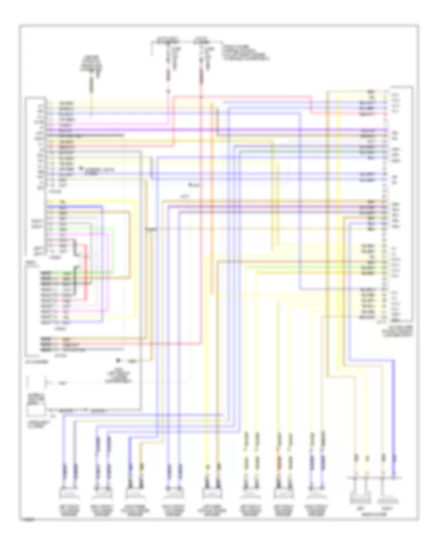 https://portal-diagnostov.com/license.html
Automotive Electricians Portal FZCO
Automotive Electricians Portal FZCO
https://portal-diagnostov.com/license.html
https://portal-diagnostov.com/license.html
Automotive Electricians Portal FZCO
Automotive Electricians Portal FZCOList of elements for Radio Wiring Diagram, Roadster without Harman Kardon for BMW M Roadster 2000:
- (center console) telephone connector
- 58g
- Ant
- Antenna amplifier am/fm
- Cd changer
- Front power distribution box (on left rear corner of engine compartment)
- Fuse f44 15a
- Fuse f9 20a
- G404 (left side of luggage compartment)
- Gal
- Hifi amplifier (on right side of luggage compt)
- Hl+
- Hl-
- Hlv+
- Hlv-
- Hot at all times
- Hot in accy, run & start
- Hr+
- Hr-
- Hrv+
- Hrv-
- I-bus
- Instrument cluster
- Interior lights system
- Left
- Left front high range speaker
- Left front low range speaker
- Left front midrange speaker
- Left rear mid-high range speaker
- Left+
- Mlh+
- Mlh-
- Mlv+
- Mlv-
- Mrh+
- Mrh-
- Mrv+
- Mrv-
- Mute
- Nca
- Radio
- Rear woofer
- Red
- Right
- Right front high range speaker
- Right front low range speaker
- Right front midrange speaker
- Right rear mid-high range speaker
- Right-
- Tlh+
- Tlh-
- Tlv+
- Tlv-
- Trh+
- Trh-
- Trv+
- Trv-
- Vl+
- Vl-
- Vr+
- Vr-
- X10015
- X10018
- X17
- X1717
- X18126
- X18180
- X18520
- X18521
- X400
SHIFT INTERLOCK
Shift Interlock Wiring Diagram for BMW M Roadster 2000
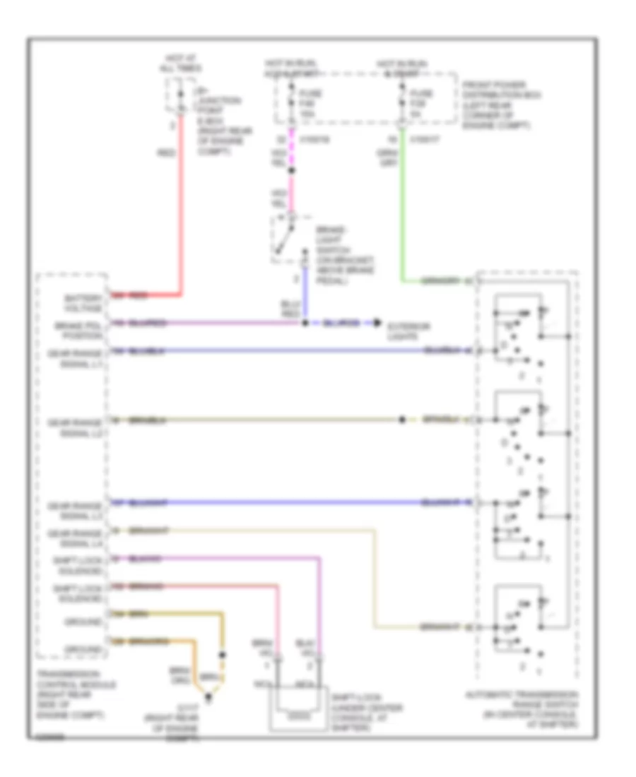 https://portal-diagnostov.com/license.html
Automotive Electricians Portal FZCO
Automotive Electricians Portal FZCO
https://portal-diagnostov.com/license.html
https://portal-diagnostov.com/license.html
Automotive Electricians Portal FZCO
Automotive Electricians Portal FZCOList of elements for Shift Interlock Wiring Diagram for BMW M Roadster 2000:
- Automatic transmission range switch (in center console, at shifter)
- B+ junction point e-box (right rear of engine compt)
- Battery voltage
- Brake pdl position
- Brake- light switch (on bracket, above brake pedal)
- Exterior lights
- Front power distribution box (left rear corner of engine compt)
- Fuse f28 5a
- Fuse f46 15a
- G117 (right rear of engine compt)
- Gear range signal l1
- Gear range signal l2
- Gear range signal l3
- Gear range signal l4
- Ground
- Hot at all times
- Hot in run & start
- Hot in run, acc & start
- Nca
- Red
- Shift lock solenoid
- Shift-lock (under center console, at shifter)
- Transmission control module (right rear side of engine compt)
- X10017
- X10018
STARTING/CHARGING
Charging Wiring Diagram for BMW M Roadster 2000
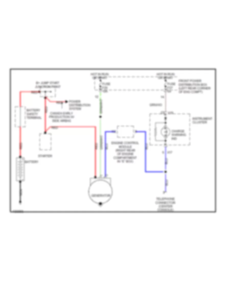 https://portal-diagnostov.com/license.html
Automotive Electricians Portal FZCO
Automotive Electricians Portal FZCO
https://portal-diagnostov.com/license.html
https://portal-diagnostov.com/license.html
Automotive Electricians Portal FZCO
Automotive Electricians Portal FZCOList of elements for Charging Wiring Diagram for BMW M Roadster 2000:
- B+ jump start junction point
- Battery
- Battery safety terminal
- Canada early production w/ side airbag
- Charge warning ind
- Engine control module (right rear of engine compartment in "e" box)
- Front power distribution box (left rear corner of eng compt)
- Fuse f26 10a
- Fuse f27 5a
- Generator
- Hot in run or start
- Instrument cluster
- Nca
- Power distribution system
- Red
- Starter
- Telephone connector (center console)
- X16
- X17
Starting Wiring Diagram for BMW M Roadster 2000
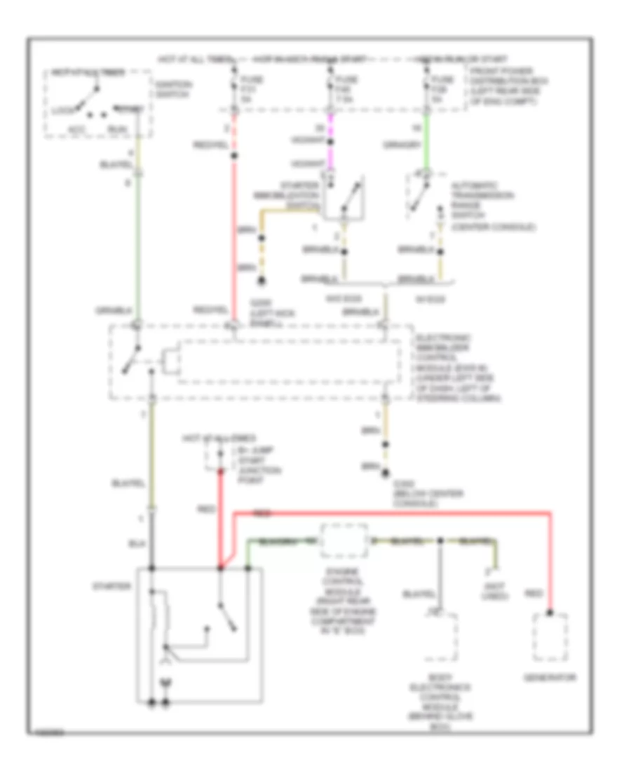 https://portal-diagnostov.com/license.html
Automotive Electricians Portal FZCO
Automotive Electricians Portal FZCO
https://portal-diagnostov.com/license.html
https://portal-diagnostov.com/license.html
Automotive Electricians Portal FZCO
Automotive Electricians Portal FZCOList of elements for Starting Wiring Diagram for BMW M Roadster 2000:
- (center console)
- (not used)
- Acc
- Automatic transmission range switch
- B+ jump start junction point
- Body electronics control module (behind glove box)
- Electronic immobilizer control module (ews iii) (under left side of dash, left of steering column)
- Engine control module (right rear side of engine compartment in "e" box)
- Front power distribution box (left rear side of eng compt)
- Fuse f28 5a
- Fuse f31 5a
- Fuse f45 7.5a
- G200 (left kick panel)
- G302 (below center console)
- Generator
- Hot at all times
- Hot in accy, run & start
- Hot in run or start
- Ignition switch
- Lock
- Red
- Run
- Start
- Starter
- Starter immobilization switch
- W/ egs
- W/o egs
SUPPLEMENTAL RESTRAINTS
Supplemental Restraints Wiring Diagram for BMW M Roadster 2000
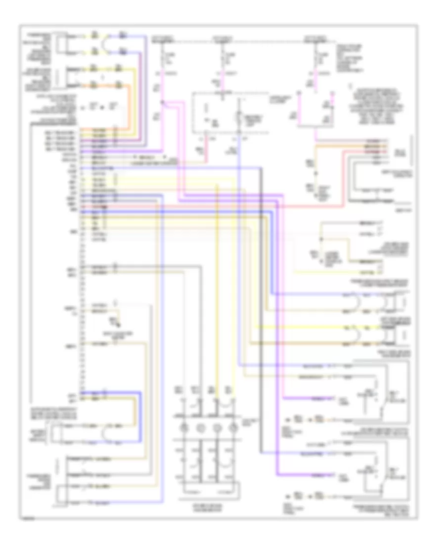 https://portal-diagnostov.com/license.html
Automotive Electricians Portal FZCO
Automotive Electricians Portal FZCO
https://portal-diagnostov.com/license.html
https://portal-diagnostov.com/license.html
Automotive Electricians Portal FZCO
Automotive Electricians Portal FZCOList of elements for Supplemental Restraints Wiring Diagram for BMW M Roadster 2000:
- (not used)
- (right kick panel) g203
- (under center console) g302
- Abbf+
- Abbf-
- Abbf2+
- Abbf2-
- Abf+
- Abf-
- Abf2+
- Abf2-
- Air bag
- Awl
- Battery safety terminal
- Belt buckled
- Belt tensioner +
- Belt tensioner -
- Belt un- buckled
- Body computer system
- Bpt+
- Bpt-
- Contact ring
- Data link connector (dlc) (partial) (2.5l & 2.8l) (on left rear side of engine compartment) (3.2l) (on right rear side of engine compartment)
- Driver's air bag gas generator
- Driver's seat belt switch (in driver's front seat belt buckle)
- Driver's side impact sensor (under driver's seat)
- Driver's side pyrotechnical belt tensioner (right side of driver's seat)
- Front power distribution box (on left rear corner of engine compartment)
- Fuse 15a
- Fuse 5a
- G203 (right kick panel)
- G302 (under center console)
- Gkbf
- Gkf
- Ground
- Hot in accy, run & start
- Hot in run & start
- Ignition
- Instrument cluster
- Left side air bag gas generator
- Nca
- Passenger side impact sensor (under passenger's seat)
- Passenger's air bag gas generator
- Passenger's seat belt switch (in passenger's front seat belt buckle)
- Passenger's side pryotechnical belt tensioner (left side of passenger's seat)
- Right side air bag gas generator
- Sbe
- Seat belt warning lamp
- Seat mat
- Seat occupancy detector
- Solid state
- Txd
- X10017
- X10018
- X16
- X17
TRANSMISSION
A/T Wiring Diagram (1 of 2) for BMW M Roadster 2000
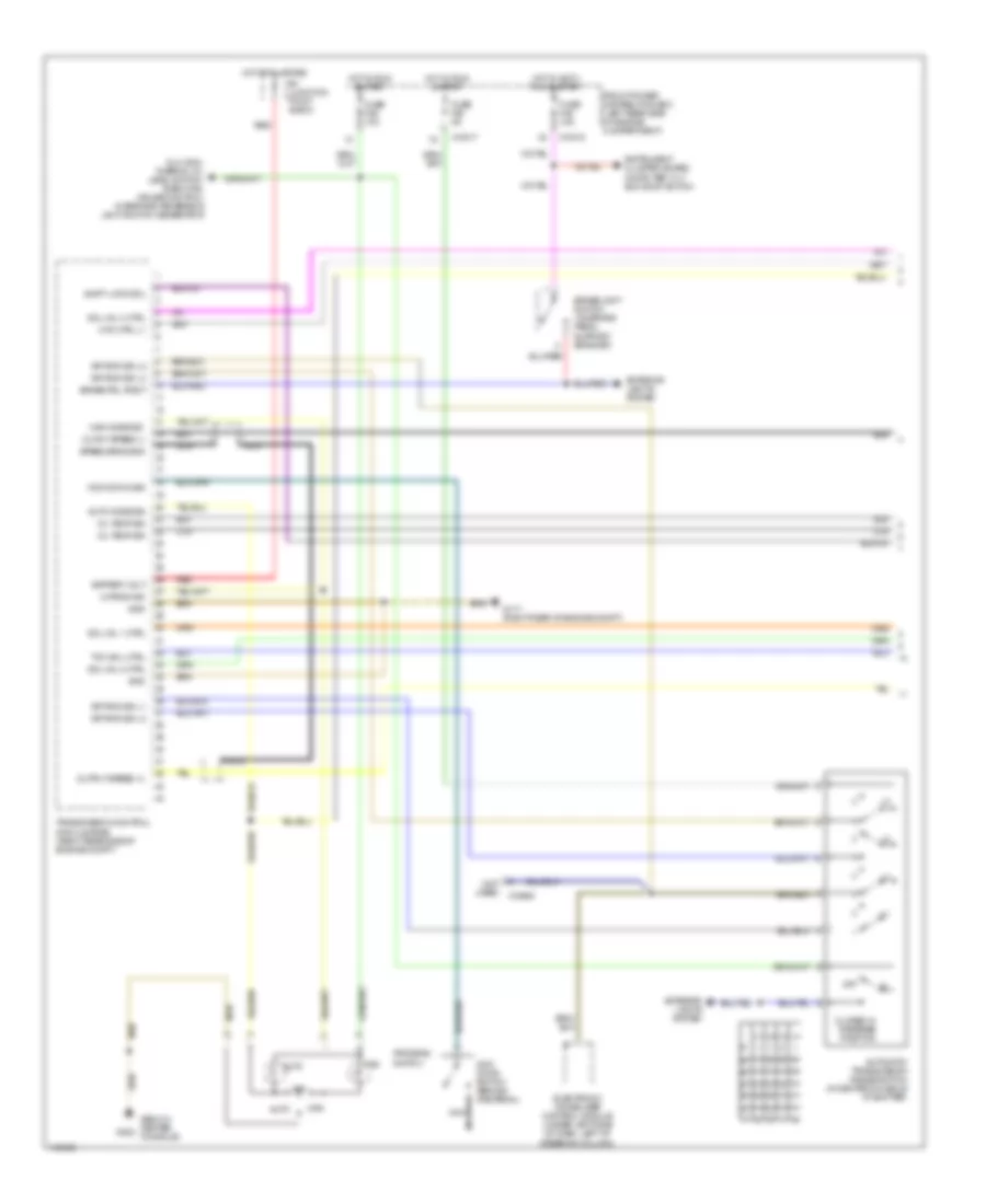 https://portal-diagnostov.com/license.html
Automotive Electricians Portal FZCO
Automotive Electricians Portal FZCO
https://portal-diagnostov.com/license.html
https://portal-diagnostov.com/license.html
Automotive Electricians Portal FZCO
Automotive Electricians Portal FZCOList of elements for A/T Wiring Diagram (1 of 2) for BMW M Roadster 2000:
- (below center g302 console)
- (not used)
- Auto
- Auto mode sig
- Automatic transmission range switch (in center console at shifter)
- B+ junction point e-box
- Battery volt
- Brake pdl posit
- Brakelight switch (on brake pedal support bracket)
- Closed in reverse position
- Clr
- Dlc, ecm, thermal oil level switch, e-box fan, cruise control interface, reversing light switch, generator
- Electronic immobilizer control module (under left side of dash, left of steering column)
- Exterior lights system
- Front power distribution box (left rear side of engine compartment)
- Fuse f26 10a
- Fuse f28 5a
- Fuse f46 15a
- G117 (right rear of engine compt)
- Gnd
- Gr rng sig l1
- Gr rng sig l2
- Gr rng sig l3
- Gr rng sig l4
- Hot at all times
- Hot in accy, run & start
- Hot in run & start
- Hyd ctrl (-)
- Instrument cluster, board computer, tilt sun roof switch
- Kick down switch (behind gas pedal)
- Kick-down sig
- M-prog ind
- Man
- Man mode sig
- Nca
- Off
- Oil temp sig
- Ouput speed (-)
- Output speed (+)
- Program switch
- Red
- Shift-lock sol
- Sol val 1 ctrl
- Sol val 2 ctrl
- Sol val 3 ctrl
- Speed sens shd
- Tcc sol ctrl
- Transmission control module (egs) (right rear side of engine compt)
- X10017
- X10018
- X18994
A/T Wiring Diagram (2 of 2) for BMW M Roadster 2000
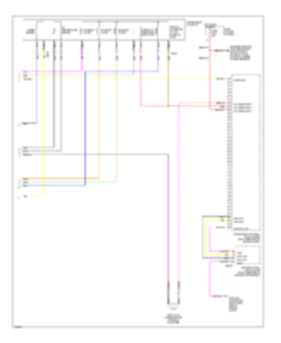 https://portal-diagnostov.com/license.html
Automotive Electricians Portal FZCO
Automotive Electricians Portal FZCO
https://portal-diagnostov.com/license.html
https://portal-diagnostov.com/license.html
Automotive Electricians Portal FZCO
Automotive Electricians Portal FZCOList of elements for A/T Wiring Diagram (2 of 2) for BMW M Roadster 2000:
- A-prog ind
- Can-high
- Can-low
- Clr
- Data link connector (right rear side of engine compt)
- Engine control module (dme) (right rear side of engine compartment)
- Fuse f204 30a
- Fuse holder (in e-box)
- Hot in run or start
- Hydraulic pressure regulator
- Leakage diagnosis pump, secondary air pump relay, solenoid valve (running losses), oxygen sensors
- Nca
- Oil temperature sensor
- Red
- Shift lock (under center console, at shifter)
- Solenoid valve 1
- Solenoid valve 2
- Solenoid valve 3
- Speed sensor
- Torque converter clutch solenoid valve
- Tramsmission control module (egs) (right rear side of engine compt)
- Transmission valve unit
- Txd2
- Txd data link
- X60002
- X8516
- X8521
WARNING SYSTEMS
Warning Systems Wiring Diagram for BMW M Roadster 2000
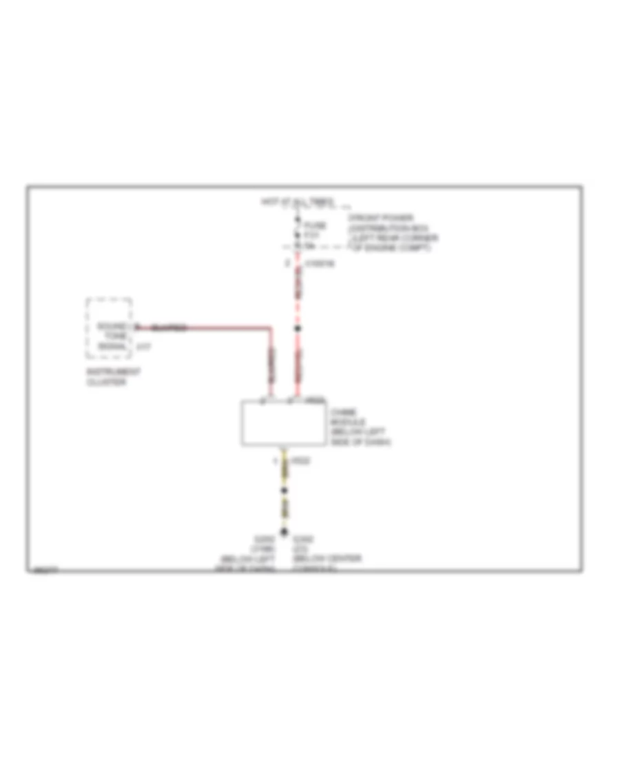 https://portal-diagnostov.com/license.html
Automotive Electricians Portal FZCO
Automotive Electricians Portal FZCO
https://portal-diagnostov.com/license.html
https://portal-diagnostov.com/license.html
Automotive Electricians Portal FZCO
Automotive Electricians Portal FZCOList of elements for Warning Systems Wiring Diagram for BMW M Roadster 2000:
- Chime module (below left side of dash)
- Front power distribution box (left rear corner of engine compt)
- Fuse f31 5a
- G202 (318ti) (below left side of dash)
- G302 (z3) (below center console)
- Hot at all times
- Instrument cluster
- Sound
- Tone signal x17
- X10018
- X522
WIPER/WASHER
Washer Jet Heater Wiring Diagram for BMW M Roadster 2000
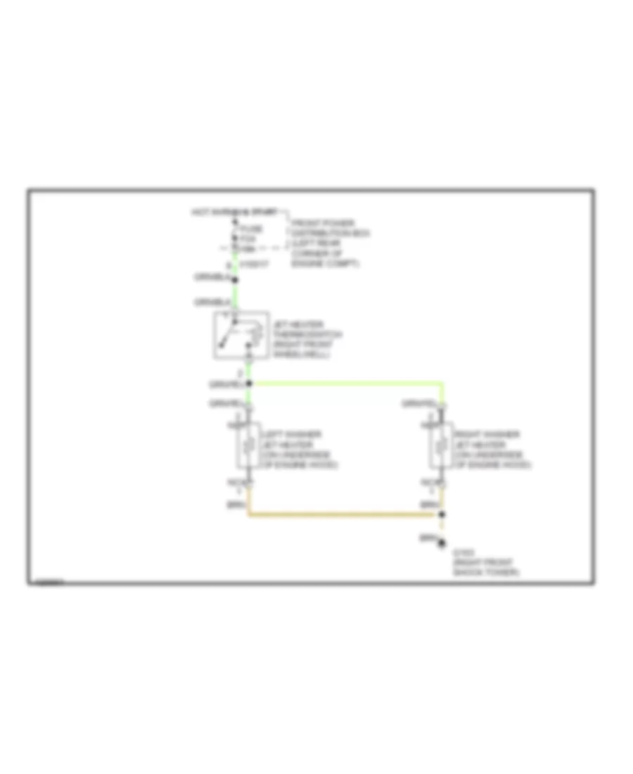 https://portal-diagnostov.com/license.html
Automotive Electricians Portal FZCO
Automotive Electricians Portal FZCO
https://portal-diagnostov.com/license.html
https://portal-diagnostov.com/license.html
Automotive Electricians Portal FZCO
Automotive Electricians Portal FZCOList of elements for Washer Jet Heater Wiring Diagram for BMW M Roadster 2000:
- Front power distribution box (left rear corner of engine compt)
- Fuse f24 10a
- G103 (right front shock tower)
- Hot in run & start
- Jet heater thermoswitch (right front wheelwell)
- Left washer jet heater (on underside of engine hood)
- Nca
- Right washer jet heater (on underside of engine hood)
Wiper/Washer Wiring Diagram, Coupe for BMW M Roadster 2000
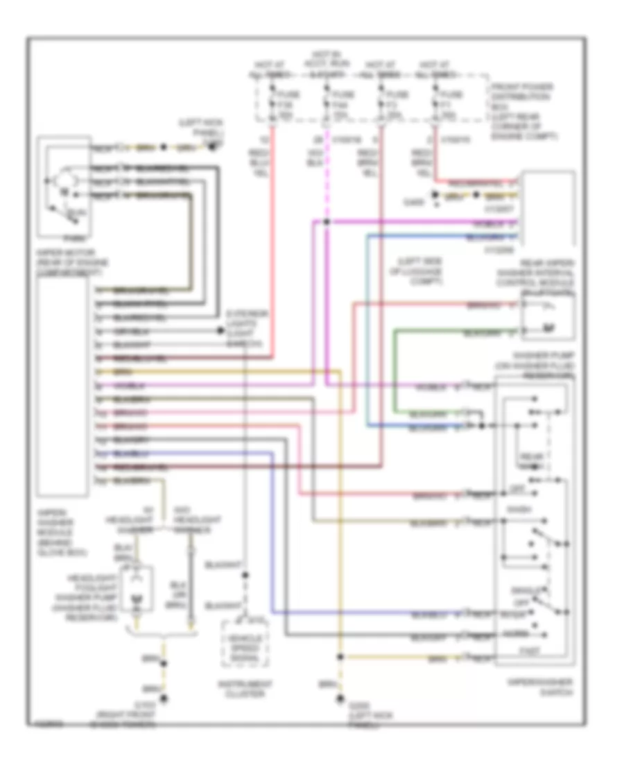 https://portal-diagnostov.com/license.html
Automotive Electricians Portal FZCO
Automotive Electricians Portal FZCO
https://portal-diagnostov.com/license.html
https://portal-diagnostov.com/license.html
Automotive Electricians Portal FZCO
Automotive Electricians Portal FZCOList of elements for Wiper/Washer Wiring Diagram, Coupe for BMW M Roadster 2000:
- & start
- (left kick panel) g200
- (left side of luggage compt)
- Exterior lights (light switch)
- Fast
- Front power distribution box (left rear corner of engine compt)
- Fuse f1 30a
- Fuse f3 30a
- Fuse f36 30a
- Fuse f44 15a
- G103 (right front shock tower)
- G200 (left kick panel)
- G400
- Headlight/ foglight washer pump (washer fluid reservoir)
- Hot at all times
- Hot in accy, run
- Instrument cluster
- Inter
- Nca
- Norm
- Off
- Park
- Rear wash
- Rear wiper/ washer interval control module (in liftgate)
- Run
- Single
- Vehicle speed signal
- W/ headlight washer
- W/o headlight washer
- Wash
- Washer pump (on washer fluid reservoir)
- Wiper motor (rear of engine compartment)
- Wiper/ washer module (behind glove box)
- Wiper/washer switch
- X10015
- X10018
- X13057
- X13268
- X17
Wiper/Washer Wiring Diagram, Roadster for BMW M Roadster 2000
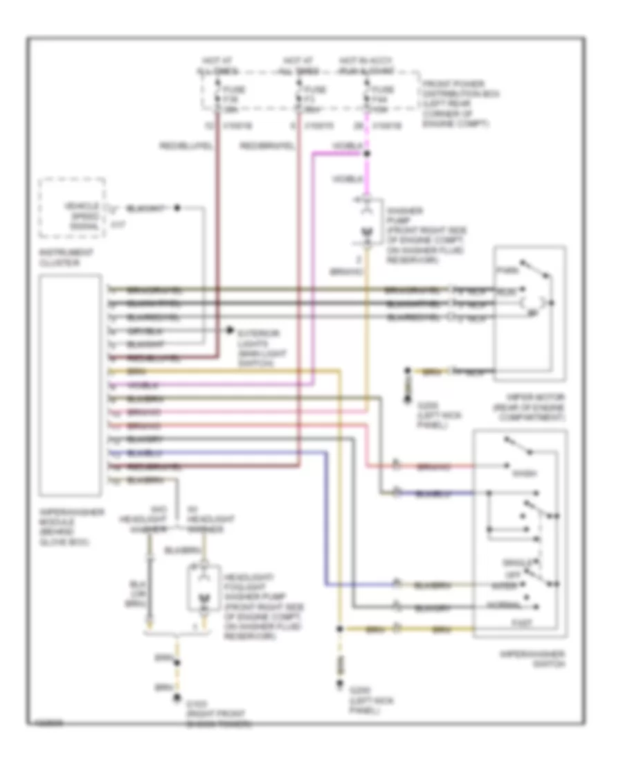 https://portal-diagnostov.com/license.html
Automotive Electricians Portal FZCO
Automotive Electricians Portal FZCO
https://portal-diagnostov.com/license.html
https://portal-diagnostov.com/license.html
Automotive Electricians Portal FZCO
Automotive Electricians Portal FZCOList of elements for Wiper/Washer Wiring Diagram, Roadster for BMW M Roadster 2000:
- Exterior lights (main light switch)
- Fast
- Front power distribution box (left rear corner of engine compt)
- Fuse f3 30a
- Fuse f36 30a
- Fuse f44 15a
- G103 (right front shock tower)
- G200 (left kick panel)
- Headlight/ foglight washer pump (front right side of engine compt, on washer fluid reservoir)
- Hot at all times
- Hot in accy, run & start
- Instrument cluster
- Inter
- Nca
- Normal
- Off
- Park
- Run
- Single
- Vehicle speed signal
- W/ headlight washer
- W/o headlight washer
- Wash
- Washer pump (front right side of engine compt, on washer fluid reservoir)
- Wiper motor (rear of engine compartment)
- Wiper/washer module (behind glove box)
- Wiper/washer switch
- X10015
- X10018
- X17

 Čeština
 Dansk
Dansk Deutsch
 Ελληνικά
 English
 English
 Español
 Suomi
Suomi Français
 Français
 עברית
עברית Hrvatski
 Magyar
 Italiano
 日本語
日本語 Nederlands
 Polski
 Português
 Português
 Română
 Русский
 Slovenčina
 Slovenščina
 Svenska
 Türkçe
 中文 (中国)
