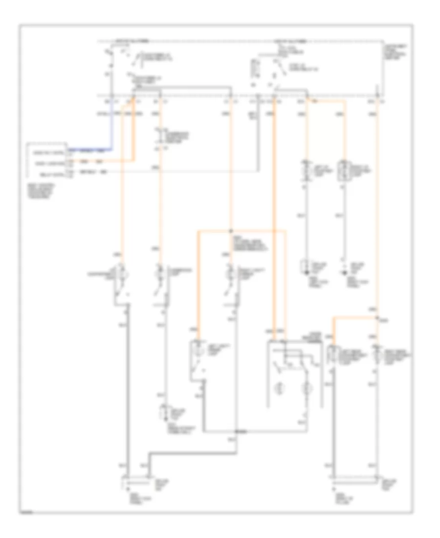
AIR CONDITIONING
Air Conditioning Wiring Diagrams, Auto A/C for Chevrolet Corvette 1997
 https://portal-diagnostov.com/license.html
Automotive Electricians Portal FZCO
Automotive Electricians Portal FZCO
https://portal-diagnostov.com/license.html
https://portal-diagnostov.com/license.html
Automotive Electricians Portal FZCO
Automotive Electricians Portal FZCO
List of elements for Air Conditioning Wiring Diagrams, Auto A/C for Chevrolet Corvette 1997:
- (base of right "a" pillar)
- (base of right "a" pillar) g203
- +5v
- A/c clu micro relay
- A/c compressor clutch
- A/c diode
- A/c mini fuse 24 10a
- A/c on
- A/c refrigerant pressure sensor (on a/c evaporator tube)
- A/c solenoid
- Act pos in
- All times
- Ambient outside temperature sensor (radiator support)
- Battery
- Bi-lev solenoid
- Blo mot maxi fuse 29 30a
- Blo spd
- Blower motor control module (below right side of dash)
- C10
- C11
- C12
- C13
- Cool fan 1 maxi fuse 49 30a
- Cool fan 1 mini relay
- Cool fan 2 maxi fuse 46 30a
- Cool fan 2 mini relay
- Cool fan 3 mini fuse 14 10a
- Cool fan 3 mini relay
- D10
- D11
- D12
- D13
- Data line
- Defrost solenoid
- G105 (rear of right front wheel- house)
- G105 (rear of right front wheelhouse)
- G203
- Ground
- Heater solenoid
- Hot at
- Hot at all times
- Hot in run
- Hot in run or start
- Hvac con mini fuse 27 10a
- Hvac mini fuse 18 10a
- Hvac programmer module (on hvac panel under radio)
- Ign
- Inside air temperature sensor (in air outlet vent, right of steering column)
- Inside temp
- Instrument panel electrical center
- Left electric actuator
- Left engine cooling fan motor
- Motor drive
- Nca
- Outside temp
- Pnk
- Powertrain control module (right side of engine compt)
- Pres sig
- Recirc solenoid
- Red
- Red/
- Relay ctrl
- Right electric actuator
- Right engine cooling fan motor
- S201 (i/p harness, 30 cm from hvac programmer connector)
- S203
- S283
- Sens gnd
- Sens ground
- Serial data
- Sol 1 ctrl
- Sol 2 ctrl
- Sol 3 ctrl
- Sol 4 ctrl
- Sol 5 ctrl
- Solid state
- Splice pack (sp206) (in i/p harness)
- Sunload in
- Sunload temperature sensor (defroster grille)
- Tan
- Underhood electrical center
- Vacuum/electric solenoid
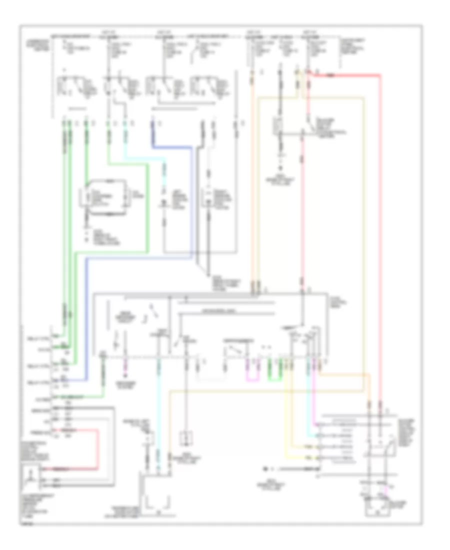
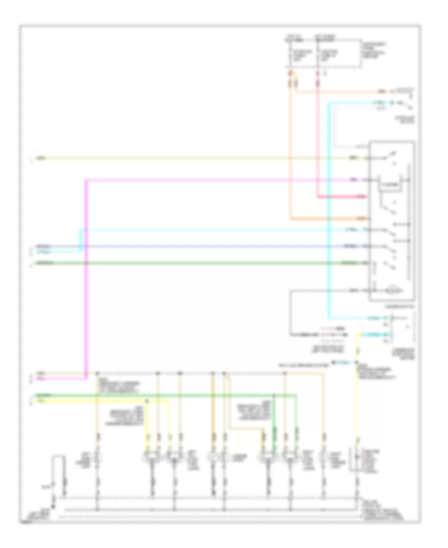
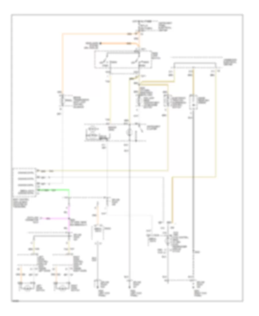
Air Conditioning Wiring Diagrams, Manual A/C for Chevrolet Corvette 1997
 https://portal-diagnostov.com/license.html
Automotive Electricians Portal FZCO
Automotive Electricians Portal FZCO
https://portal-diagnostov.com/license.html
https://portal-diagnostov.com/license.html
Automotive Electricians Portal FZCO
Automotive Electricians Portal FZCOList of elements for Air Conditioning Wiring Diagrams, Manual A/C for Chevrolet Corvette 1997:
- (base of left "a" pillar) g200
- +5v
- A c2
- A/c clu micro relay
- A/c compres- sor clutch
- A/c diode
- A/c mini fuse 24 10a
- A/c on
- A/c refrigerant pressure sensor (on a/c evaporator tube)
- A/c req
- Air recirc
- Air source logic
- All times
- Blo mot maxi fuse 49 30a
- Blower motor
- Blower motor control module (right side of dash)
- Blower motor relay (in electrical center)
- Cool fan 1 maxi fuse 49 30a
- Cool fan 1 mini relay
- Cool fan 2 maxi fuse 46 30a
- Cool fan 2 mini relay
- Cool fan 3 mini fuse 14 10a
- Cool fan 3 mini relay
- Defogger system
- Defrost/defog
- G tan
- G105 (rear of right front wheel- house)
- G105 (rear of right front wheelhouse)
- G203 (base of right "a" pillar)
- Hot at
- Hot in run
- Hot in run or start
- Hvac mini fuse 18 10a
- Hvac con mini fuse 27 10a
- Hvac control head
- Instrument panel electrical center
- Left engine cooling fan motor
- Nca
- Off
- Powertrain control module (right side of engine compt)
- Press sig
- Rear defogger circuit
- Red
- Relay ctrl
- Right engine cooling fan motor
- Sens gnd
- Tan
- Temp control
- Temperature door motor (on heater case)
- Underhood electrical center
ANTI-LOCK BRAKES
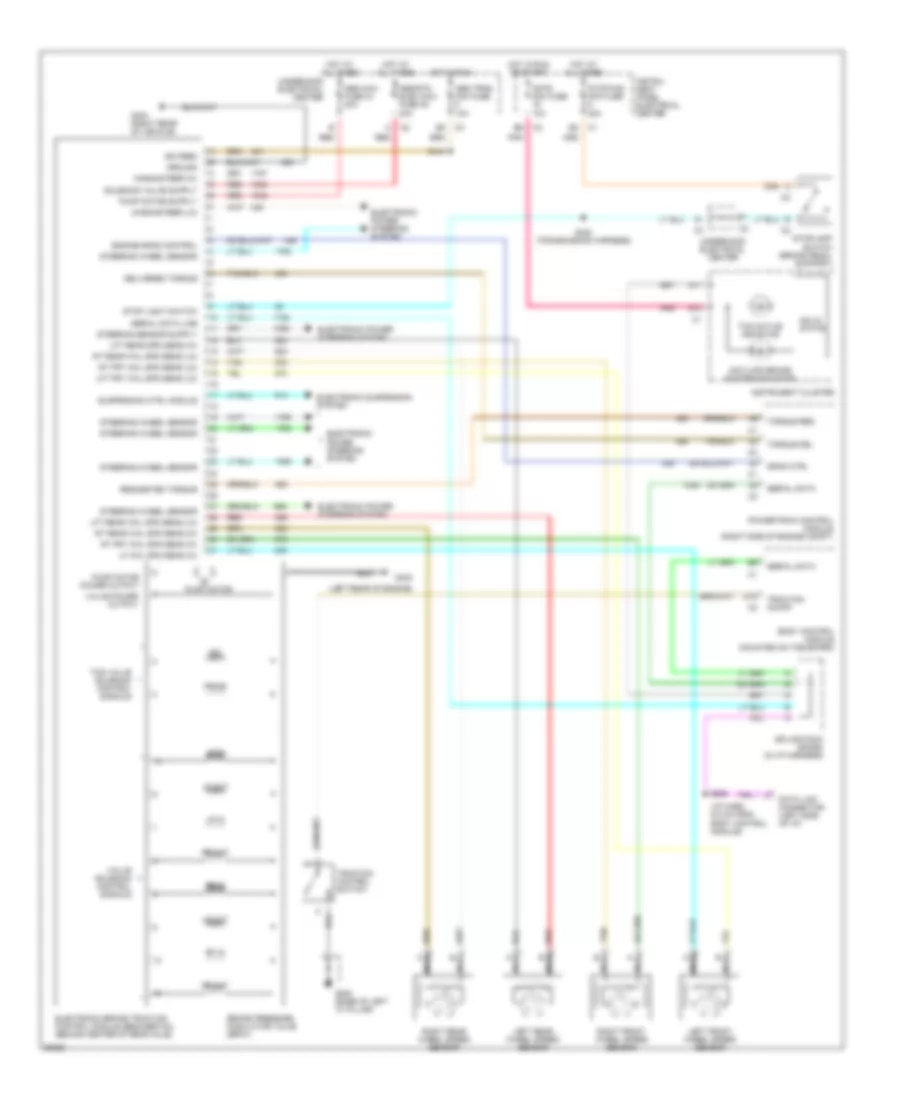
Anti-lock Brake Wiring Diagrams for Chevrolet Corvette 1997
 https://portal-diagnostov.com/license.html
Automotive Electricians Portal FZCO
Automotive Electricians Portal FZCO
https://portal-diagnostov.com/license.html
https://portal-diagnostov.com/license.html
Automotive Electricians Portal FZCO
Automotive Electricians Portal FZCOList of elements for Anti-lock Brake Wiring Diagrams for Chevrolet Corvette 1997:
- (i/p harn, 6.5 cm from body control module)
- (left rear of engine)
- A11
- A13
- Abs maxi fuse 44 40a
- Abs trns mini fuse 10a
- Abs/rtd elec maxi fuse 45 20a
- Antilock brake system indicator
- Body control module (mounted on toe board)
- Brake pressure modulator valve (bpmv)
- Cstr mini fuse 10a
- D15
- Data link connector (left side of i/p)
- Delivered torque
- Drag ctrl
- Electronic brake traction control module (ebcm/ebtcm) (behind center of rear axle)
- Electronic power steering system
- Electronic suspension system
- Engine drag control
- G200 (base of left "a" pillar)
- G402
- G403 (right rear of vehicle)
- Ground
- Hot at all times
- Hot in run
- Hot in run or start
- Ign feed
- Instru- ment panel electrical center
- Instrument cluster
- Iso
- Left front wheel speed sensor
- Left rear wheel speed sensor
- Lf in
- Lf out
- Lf whl spd sens (hi)
- Lft frt whl spd sens (lo)
- Lft rear spd sens (hi)
- Lft rear whl spd sens (lo)
- Lr in
- Lr out
- Magnasteer (hi)
- Magnasteer (lo)
- Nca
- Pnk
- Powertrain control module (right side of engine compt)
- Prime
- Pump motor
- Pump motor power output
- Red
- Requested torque
- Rf in
- Rf out
- Right front wheel speed sensor
- Right rear wheel speed sensor
- Rr in
- Rr out
- Rt frt whl spd sens (hi)
- Rt frt whl spd sens (lo)
- Rt rear whl spd sens (hi)
- Rt rear whl spd sens (lo)
- S208
- S418
- S420 (transmission harness)
- Serial data
- Serial data line
- Solid state
- Splice pack (sp206) (in i/p harness)
- Steering wheel sensor
- Stop light switch
- Stop/haz mini fuse 20a
- Stoplamp switch (brake pedal support)
- Suspension ctrl module
- Tan
- Tcs active indicator
- Tcs valve solenoid control signals
- Torque del
- Torque req
- Traction control switch
- Traction on/off
- Underhood electrical center
- Valve power output
- Valve solenoid control signals
ANTI-THEFT
Anti-theft Wiring Diagram for Chevrolet Corvette 1997
 https://portal-diagnostov.com/license.html
Automotive Electricians Portal FZCO
Automotive Electricians Portal FZCO
https://portal-diagnostov.com/license.html
https://portal-diagnostov.com/license.html
Automotive Electricians Portal FZCO
Automotive Electricians Portal FZCOList of elements for Anti-theft Wiring Diagram for Chevrolet Corvette 1997:
- A nca
- A/t
- Acc
- B nca
- B10
- Body control module (mounted on toe board)
- C14
- Clutch pedal position switch (behind clutch pedal)
- Crk fuse 14 10a
- D16
- Driver dr ajar
- Exterior lights system
- F/tank door fuse 32 15a
- F12
- Fog lamp switch/ rear compartment lid release switch
- G200 (base of left "a" pillar)
- G203 (base of right "a" pillar)
- Ground
- Horn rly
- Horn system
- Hot at all times
- Ignition key
- Ignition key lock cylinder
- Ignition switch
- Instrument panel electrical center
- Key in
- Key out
- Key sw in
- Left door control module (bottom of left door)
- Left door key switch
- Lock
- Lt drl rly
- M/t
- Park/neutral switch (on transmission)
- Pass dr ajar
- Pass key rtn
- Pass-key in
- Per/mlp rly
- Powertrain control module (right side of engine compt)
- Resistor pellet
- Right door ajar indicator switch
- Right door control module (bottom of right door)
- Right door key switch
- Rr compt rel
- Rt door ajar
- Rt drl rly
- Run
- S288
- Serial data
- Splice pack (sp206) (in i/p harness)
- Start
- Starter enable
- Starting & charging system
- Tan
- Theft deterrent relay
BODY COMPUTER
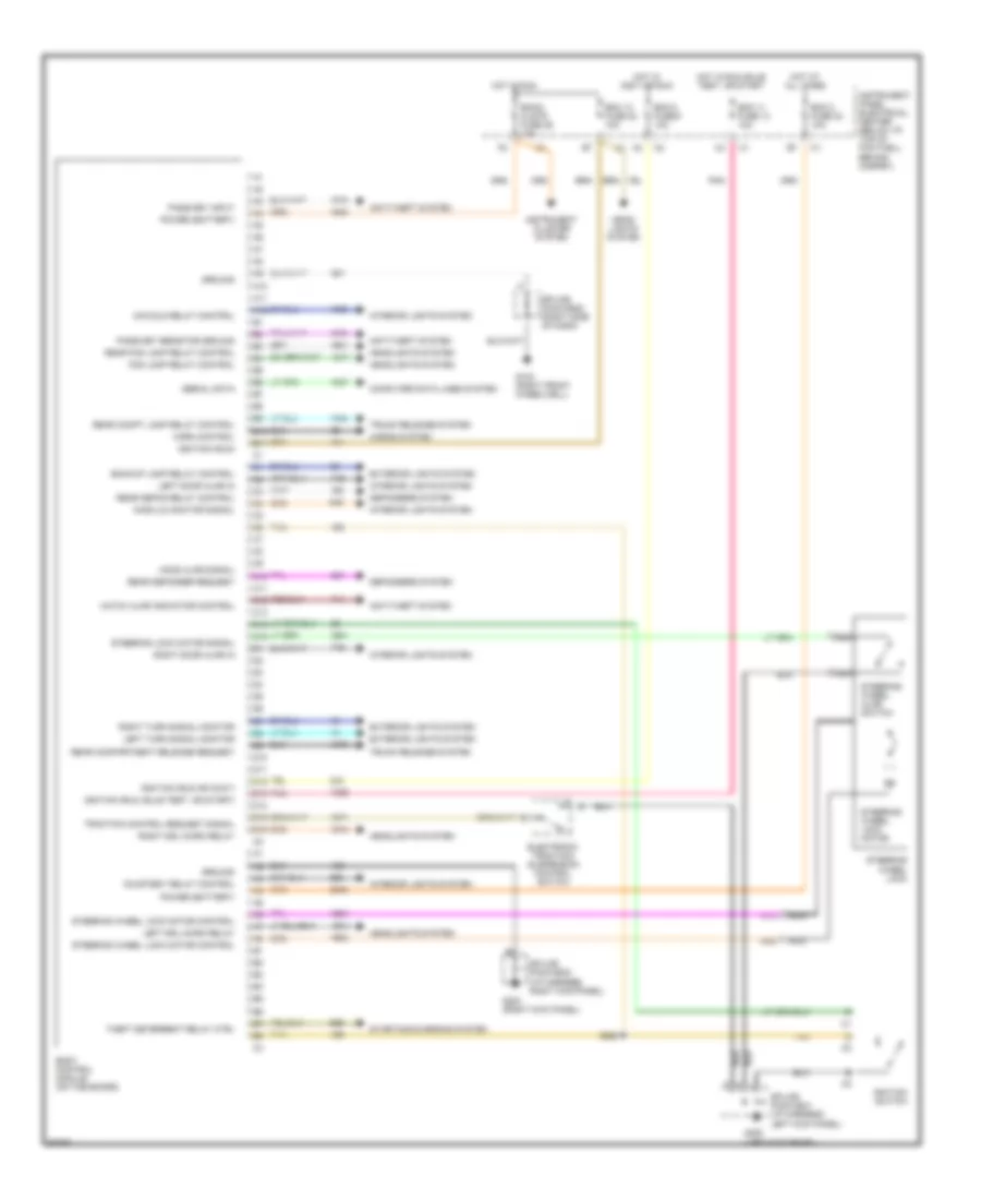
Body Computer Wiring Diagrams for Chevrolet Corvette 1997
 https://portal-diagnostov.com/license.html
Automotive Electricians Portal FZCO
Automotive Electricians Portal FZCO
https://portal-diagnostov.com/license.html
https://portal-diagnostov.com/license.html
Automotive Electricians Portal FZCO
Automotive Electricians Portal FZCOList of elements for Body Computer Wiring Diagrams for Chevrolet Corvette 1997:
- A10
- A11
- A12
- Anti-theft system
- B10
- B11
- Backup lamp relay control
- Bcm 11 fuse 13 10a
- Bcm 13 fuse 22 10a
- Bcm 2 fuse 23 10a
- Bcm a fuse 9 10a
- Bcm2/ clstr fuse 25 10a
- Body control module (on toe board)
- C10
- C11
- C12
- C13
- C14
- C15
- Computer data lines system
- Courtesy relay control
- D10
- D11
- D12
- D13
- D14
- D15
- D16
- Defoggers system
- Electronic traction/ suspension control switch
- Exterior lights system
- Fog lamp relay control
- G103 (right front wheelwell)
- G200 (left kick panel)
- G203 (right kick panel)
- Ground
- Hatch ajar indicator control
- Head- lights system
- Headlights system
- Hood ajar signal
- Horn control
- Horns system
- Hot at all times
- Hot in accy or run
- Hot in run
- Hot in run, bulb test, or start
- Ignition (run or accy)
- Ignition (run)
- Ignition (run, bulb test, or start)
- Ignition switch
- Inadvld monitor signal
- Inavdld relay control
- Instrument cluster system
- Instrument panel electrical center (below i/p, top of footwell behind carpet)
- Interior lights system
- Left door ajar in
- Left drl micro relay
- Left turn signal monitor
- Nca
- Pass-key input
- Pass-key resistor ground
- Pnk
- Power (battery)
- Rear compartment release request
- Rear compt lamp relay control
- Rear defog relay control
- Rear defogger request
- Rear fog lamp relay control
- Right door ajar in
- Right drl micro relay
- Right turn signal monitor
- S288
- Serial data
- Splice pack #201 (i/p harness, left kick panel)
- Splice pack #202 (i/p harness, right kick panel)
- Splice pack #208 (right side of dash)
- Starting/charging system
- Steering lock motor signal
- Steering wheel ajar switch
- Steering wheel lock
- Steering wheel lock motor
- Steering wheel lock motor control
- Tan
- Theft deterrent relay ctrl
- Traction control request signal
- Trunk release system
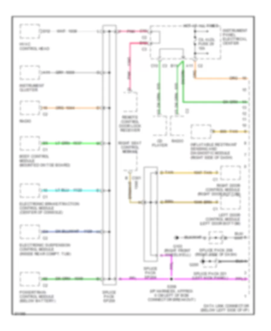
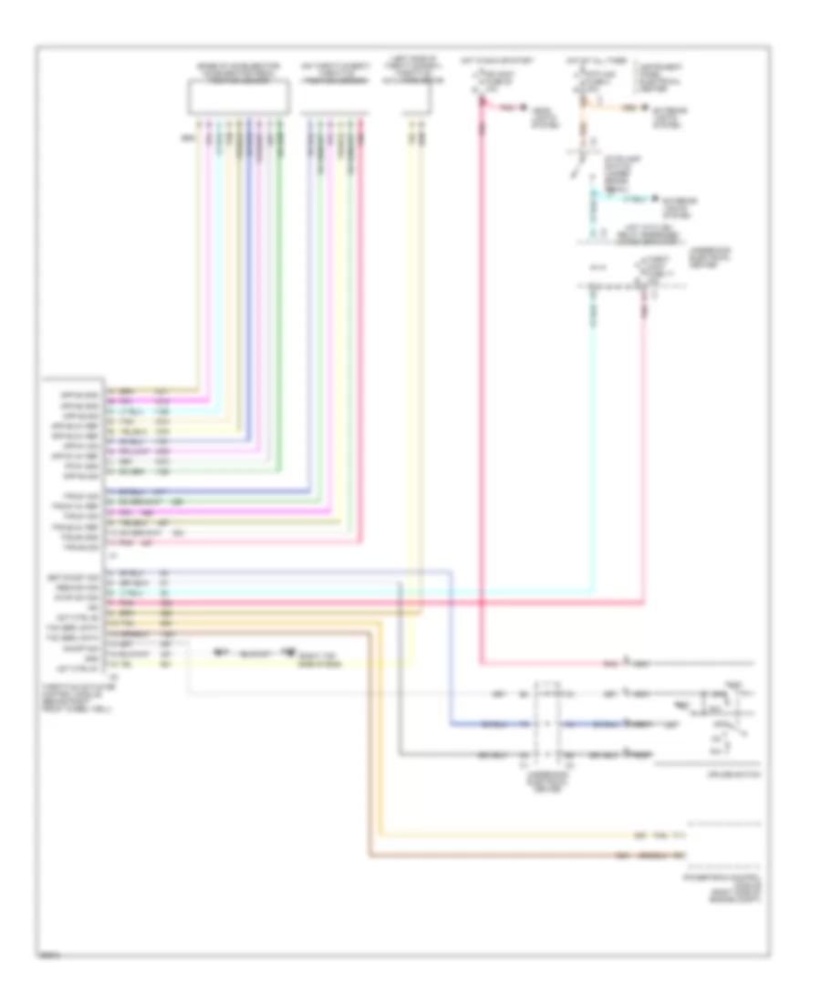
COMPUTER DATA LINES
Computer Data Lines for Chevrolet Corvette 1997
 https://portal-diagnostov.com/license.html
Automotive Electricians Portal FZCO
Automotive Electricians Portal FZCO
https://portal-diagnostov.com/license.html
https://portal-diagnostov.com/license.html
Automotive Electricians Portal FZCO
Automotive Electricians Portal FZCOList of elements for Computer Data Lines for Chevrolet Corvette 1997:
- A11
- B11
- Body control module (mounted on toe board)
- C/l aldl fuse 29 10a
- C10
- Cd player
- D12
- Data link connector (below left side of i/p)
- Electronic brake/traction control module (center of console)
- Electronic suspension control module (inside rear compt. tub)
- G103 (right front wheelwell)
- G200
- Hot at all times
- Hvac control head
- Inflatable restraint sensing and diagnostic module (right side of dash)
- Instrument cluster
- Instrument panel electrical center
- Left door control module (left door bottom)
- Pnk
- Powertrain control module (below battery)
- Radio
- Remote control door lock receiver
- Right door control module (right door bottom)
- Right seat control module
- S208 (i/p harness, approx 6 cm left of bcm connector breakout)
- Splice pack 201 (left kick panel)
- Splice pack 208 (right side of dash)
- Splice pack sp204
- Splice pack sp206
- Tan
- Tan d
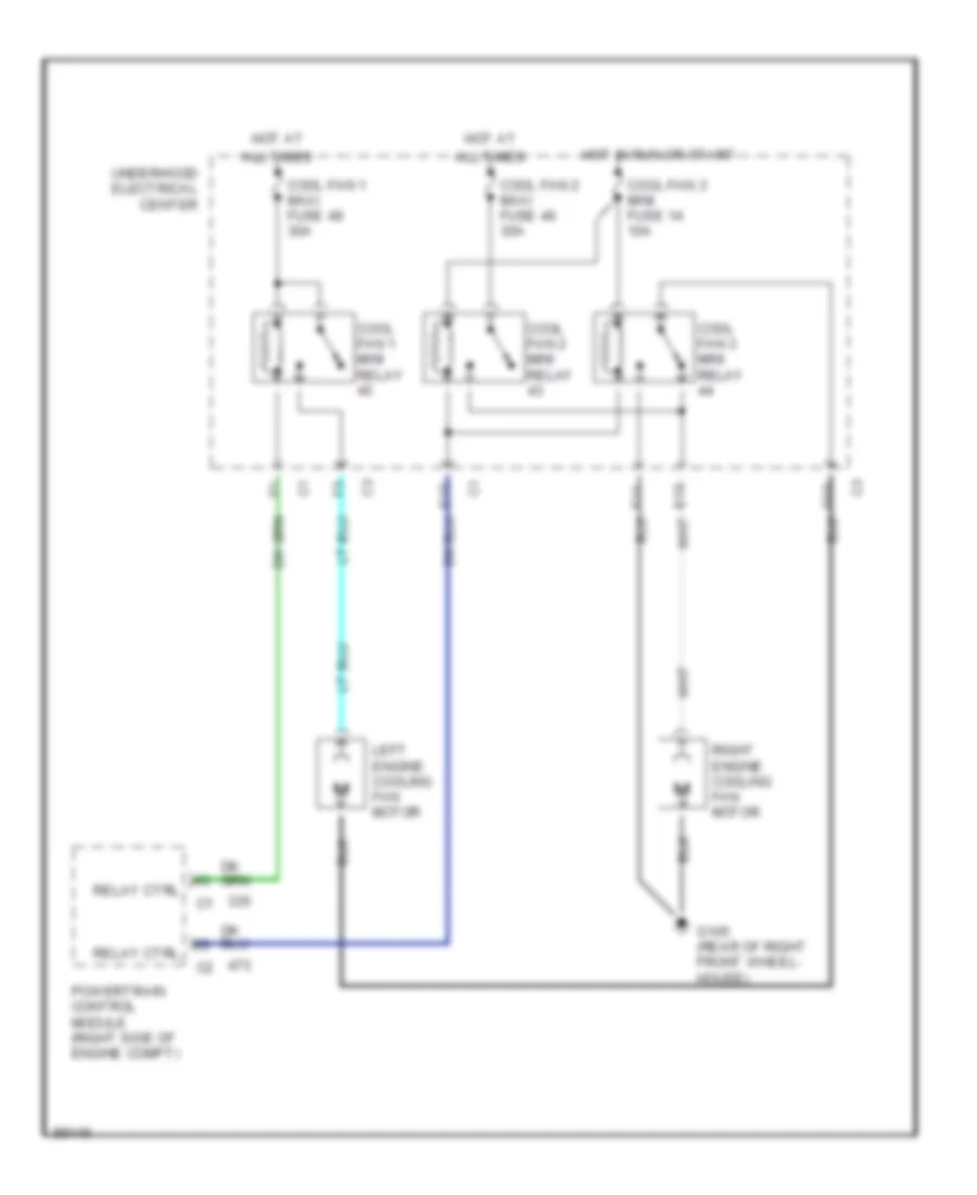
COOLING FAN
Cooling Fan Wiring Diagram for Chevrolet Corvette 1997
 https://portal-diagnostov.com/license.html
Automotive Electricians Portal FZCO
Automotive Electricians Portal FZCO
https://portal-diagnostov.com/license.html
https://portal-diagnostov.com/license.html
Automotive Electricians Portal FZCO
Automotive Electricians Portal FZCOList of elements for Cooling Fan Wiring Diagram for Chevrolet Corvette 1997:
- All times
- Cool fan 1 maxi fuse 49 30a
- Cool fan 1 mini relay
- Cool fan 2 maxi fuse 46 30a
- Cool fan 2 mini relay
- Cool fan 3 mini fuse 14 10a
- Cool fan 3 mini relay
- G105 (rear of right front wheel- house)
- Hot at
- Hot in run or start
- Left engine cooling fan motor
- Powertrain control module (right side of engine compt)
- Relay ctrl
- Right engine cooling fan motor
- Underhood electrical center
CRUISE CONTROL
Cruise Control Wiring Diagram for Chevrolet Corvette 1997
 https://portal-diagnostov.com/license.html
Automotive Electricians Portal FZCO
Automotive Electricians Portal FZCO
https://portal-diagnostov.com/license.html
https://portal-diagnostov.com/license.html
Automotive Electricians Portal FZCO
Automotive Electricians Portal FZCOList of elements for Cruise Control Wiring Diagram for Chevrolet Corvette 1997:
- (base of accelerator) accelerator pedal position sensor
- (left side of throttle body) throttle actuator motor
- (on throttle body) throttle position sensor
- (right top side of eng)
- Act ctrl #1
- Act ctrl #2
- App #1 5v ref
- App #1 sig
- App #2 5v ref
- App #2 gnd
- App #2 sig
- App #3 5v ref
- App #3 gnd
- App #3 sig
- Cr cont a
- Cruise switch
- Exterior lights system
- Fuse 20 10a b
- Fuse 8 20a b
- G120
- Gnd
- Head- lights system
- Hot at all times
- Hot in run or start
- Hot with ign relay energized (in run or start)
- Ign
- Instrument panel electrical center
- Nca
- Off
- On/off sig
- Pnk
- Powertrain control module (right side of engine compt)
- Pp #1 gnd
- R/a
- Res/acc sig
- S120
- Set/coast sig
- Stop sw sig
- Stoplamp switch (under brake pedal) c2
- Stp haz a
- Tac serl data
- Tan
- Throt cont fuse 17 15a
- Throttle actuator control module (behind right front wheel well)
- Tps #1 5v ref
- Tps #1 sig
- Tps #2 5v ref
- Tps #2 gnd
- Tps #2 sig
- Underhood electrical center
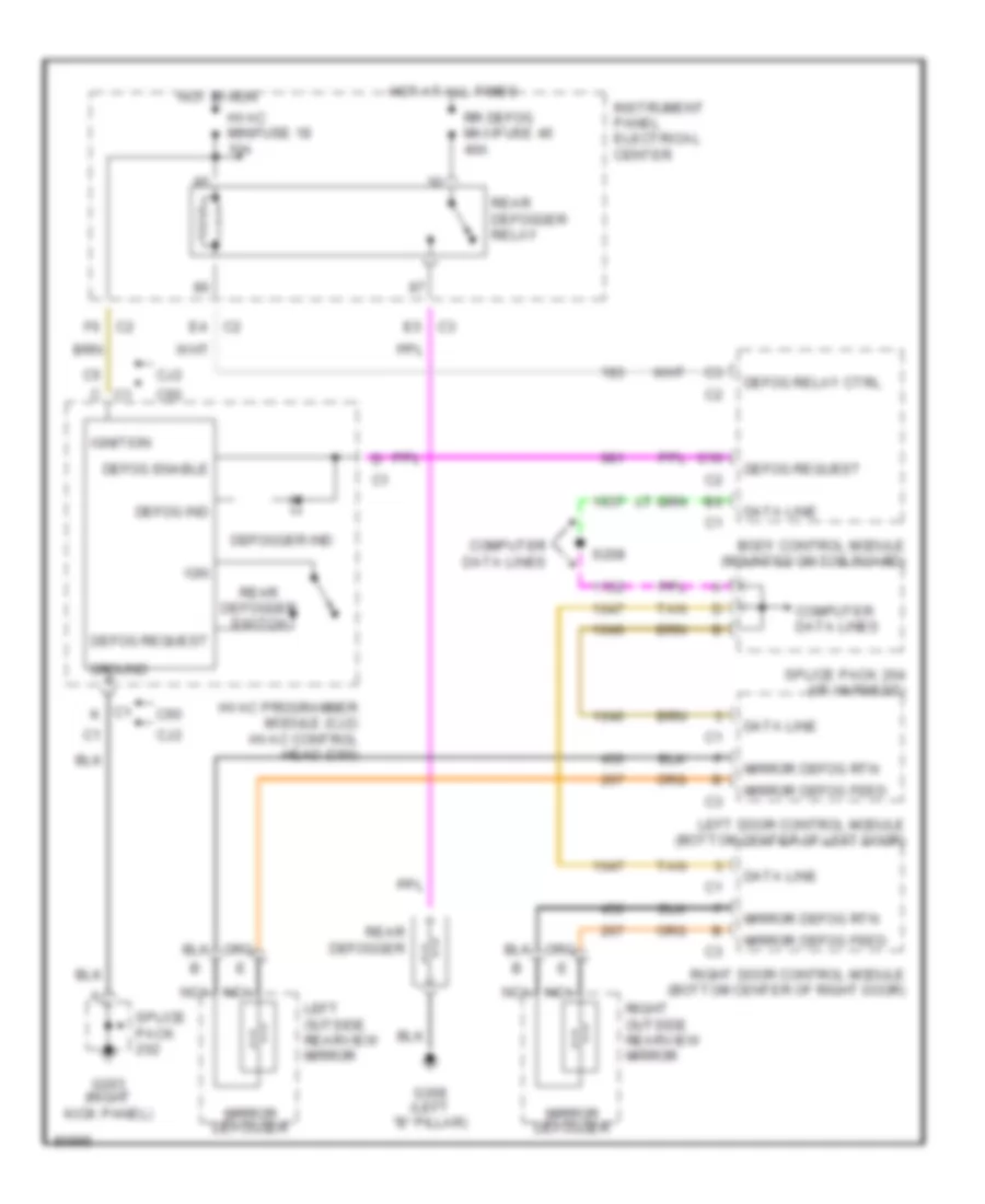
DEFOGGERS
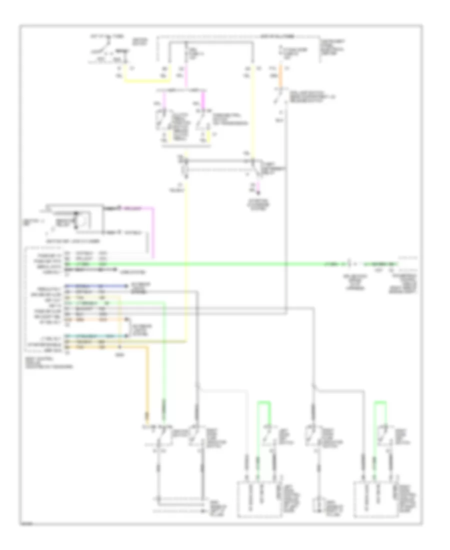
Defogger Wiring Diagram for Chevrolet Corvette 1997
 https://portal-diagnostov.com/license.html
Automotive Electricians Portal FZCO
Automotive Electricians Portal FZCO
https://portal-diagnostov.com/license.html
https://portal-diagnostov.com/license.html
Automotive Electricians Portal FZCO
Automotive Electricians Portal FZCOList of elements for Defogger Wiring Diagram for Chevrolet Corvette 1997:
- Body control module (mounted on toe board)
- C1 c
- C1 k
- C10
- C2 e4
- C2 f6
- C60
- Cj2
- Computer data lines
- Data line
- Defog enable
- Defog ind
- Defog relay ctrl
- Defog request
- Defogger ind
- E5 c3
- G203 (right kick panel)
- G308 (left "b" pillar)
- Ground
- Hot at all times
- Hot in run
- Hvac minifuse 18 10a
- Hvac programmer module (cj2) hvac control head (c60)
- Ign
- Ignition
- Instrument panel electrical center
- Left door control module (bottom center of left door)
- Left outside rearview mirror
- Mirror defog feed
- Mirror defog rtn
- Mirror defogger
- Nca
- Rear defogger
- Rear defogger relay
- Rear defogger switch
- Right door control module (bottom center of right door)
- Right outside rearview mirror
- Rr defog maxifuse 46 40a
- S208
- Splice pack
- Splice pack 204 (i/p harness)
- Tan
ELECTRONIC POWER STEERING
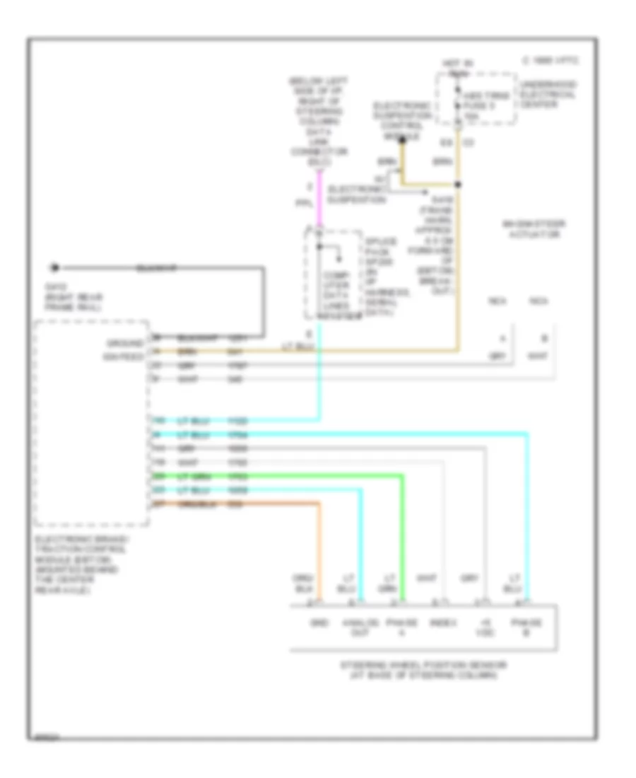
Electronic Power Steering Wiring Diagram for Chevrolet Corvette 1997
 https://portal-diagnostov.com/license.html
Automotive Electricians Portal FZCO
Automotive Electricians Portal FZCO
https://portal-diagnostov.com/license.html
https://portal-diagnostov.com/license.html
Automotive Electricians Portal FZCO
Automotive Electricians Portal FZCOList of elements for Electronic Power Steering Wiring Diagram for Chevrolet Corvette 1997:
- (below left side of i/p, right of steering column) data link connector (dlc)
- +5 vdc
- 1995 vftc c
- Abs trns fuse 5 10a
- Analog out
- Comp- uter data lines system
- E8 c3
- Electronic brake/ traction control module (ebtcm) (mounted behind the center rear axle)
- Electronic suspention control module
- G412 (right rear frame rail)
- Gnd
- Ground
- Hot in run
- Ign feed
- Index
- Magnasteer actuator
- Nca
- Phase a
- Phase b
- S418 (trans harn, approx 6.5 cm forward of (ebtcm) break- out)
- Splice pack sp205 (in i/p harness, serial data)
- Steering wheel position sensor (at base of steering column)
- Underhood electrical center
- W/ electronic suspention
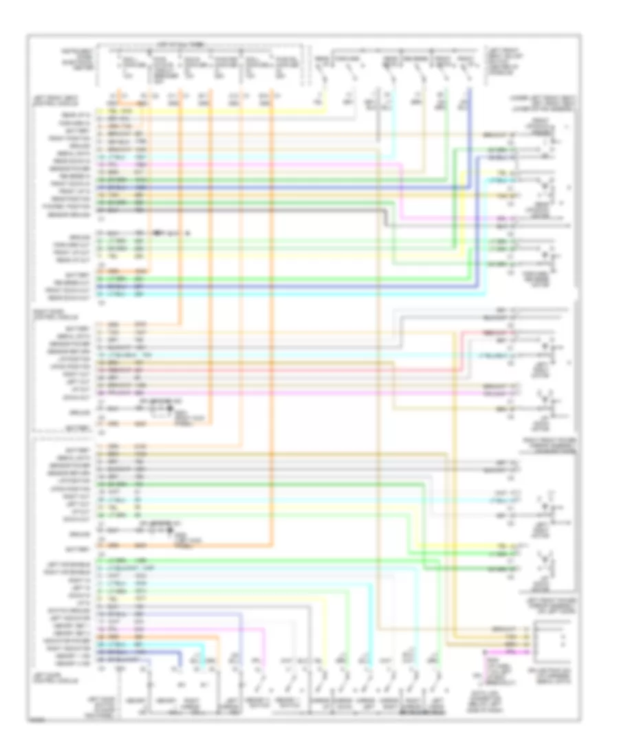
ELECTRONIC SUSPENSION
Electronic Suspension Wiring Diagram for Chevrolet Corvette 1997
 https://portal-diagnostov.com/license.html
Automotive Electricians Portal FZCO
Automotive Electricians Portal FZCO
https://portal-diagnostov.com/license.html
https://portal-diagnostov.com/license.html
Automotive Electricians Portal FZCO
Automotive Electricians Portal FZCOList of elements for Electronic Suspension Wiring Diagram for Chevrolet Corvette 1997:
- (i/p harness, near breakout to front bussed electrical) center) s204
- 5 v ref
- A c5
- A10
- A11
- A12
- A7 c3
- Abs trns fuse 10a
- Abs/rtd elec fuse 20a
- B10
- B11
- B12
- Battery
- Body control module (on toe board)
- C10
- C11
- C12
- C13
- Chassis pitch
- D10
- D11
- D12
- D13
- Data link connector (below left side of i/p, right of steering wheel)
- Electronic brake/traction control module (rear of vehicle behind center of axle)
- Electronic traction/ suspension control switch
- G417 (right rear frame rail)
- Ground
- Hot at all times
- Hot in run
- Ignition
- Instrument cluster
- Interior lights system
- Left front electronic position sensor (right side of left front shock spring)
- Left front shock absorber solenoid (front bottom of right front shock)
- Left rear electronic sensor position (left side of left rear shock spring)
- Left rear shock absorber solenoid (rear bottom of left rear shock)
- Lf pos sens
- Lf sol high
- Lf sol low
- Lr pos sens
- Lr sol high
- Lr sol low
- Nca
- Orn
- Perf
- Powertrain control module (right side of engine compt above battery)
- Real time damping (rtd) micro relay 41
- Real time damping module (inside rear tub)
- Red
- Rf pos sens
- Rf sol high
- Rf sol low
- Right front electronic position sensor (right side of right front shock spring)
- Right front shock absorber solenoid (front bottom of right front shock)
- Right rear electronic position sensor (right side of right rear shock spring)
- Right rear shock absorber solenoid (rear bottom of right rear shock)
- Rr pos sens
- Rr sol high
- Rr sol low
- Rtd fuse 7 10a
- Rtd relay
- S208
- S418
- Serial data
- Splice pack #206 (i/p harness)
- Sport
- Steering pos
- Tour
- Underhood electrical center (right side of engine compt above battery)
- Vehicle speed
ENGINE PERFORMANCE
5.7L
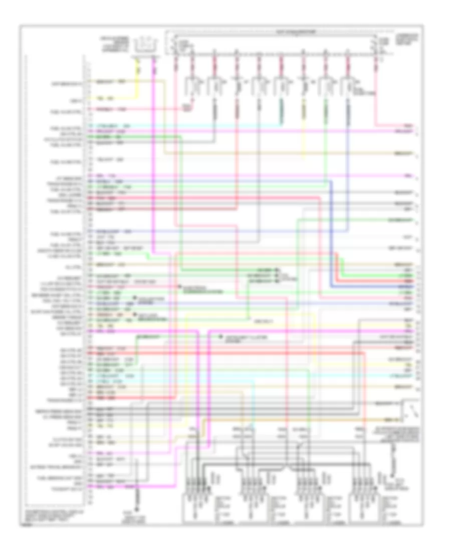
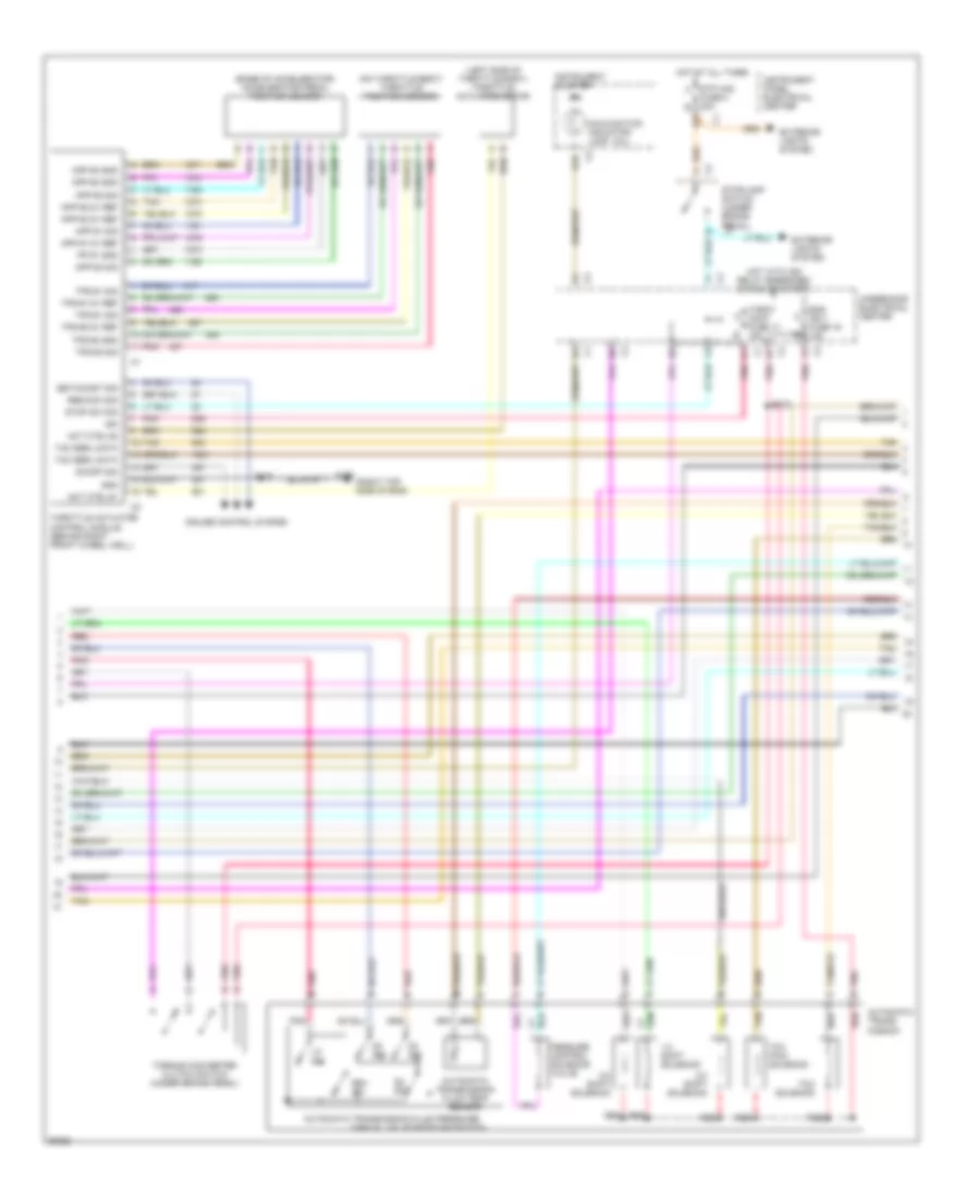
5.7L (VIN G), Engine Performance Wiring Diagrams (1 of 4) for Chevrolet Corvette 1997
 https://portal-diagnostov.com/license.html
Automotive Electricians Portal FZCO
Automotive Electricians Portal FZCO
https://portal-diagnostov.com/license.html
https://portal-diagnostov.com/license.html
Automotive Electricians Portal FZCO
Automotive Electricians Portal FZCOList of elements for 5.7L (VIN G), Engine Performance Wiring Diagrams (1 of 4) for Chevrolet Corvette 1997:
- (c60 only)
- (right top side of eng)
- (top left plug side of eng)
- 1-2 ss valve ctrl
- 1-4 lmp or 2-3 ss ctrl
- 2nd/3th gear or 3-2 ss
- 375 or 1223
- 451c
- 451h
- 587 or 687
- A/c clutch status
- A/c request
- A/c system
- Anti-lock brake system
- Ckp sens sig in
- Clutch sw sig
- Cmp sens sig in
- Cool fan 1 rly ctrl
- Cooling fans system
- Desire torque
- Electronic suspension system
- Evap can purge val ctrl
- Evap vac sw sig
- Evaporative emission vacuum purge solenoid (left side of eng, on intake manifold)
- Extend travel brake sw
- Fuel inj #1 ctrl
- Fuel inj #2 ctrl
- Fuel inj #3 ctrl
- Fuel inj #4 ctrl
- Fuel inj #5 ctrl
- Fuel inj #6 ctrl
- Fuel inj #7 ctrl
- Fuel inj #8 ctrl
- Fuel injectors
- Fuel sending unit gnd
- G112
- G120
- Gnd
- Gnd jumper
- Hot in run or start
- Iat sens gnd
- Ign
- Ign ctrl #1
- Ign ctrl #2
- Ign ctrl #3
- Ign ctrl #4
- Ign ctrl #5
- Ign ctrl #6
- Ign ctrl #7
- Ign ctrl #8
- Ign ctrl sig
- Ignition coil/ module #1 (at top of cylinder)
- Ignition coil/ module #3 (at top of cylinder)
- Ignition coil/ module #5 (at top of cylinder)
- Ignition coil/ module #7 (at top of cylinder)
- Injr1 fuse 22 15a
- Injr2 fuse 15a
- Instrument cluster system
- Maf sens sig
- Mil ctrl
- Nca
- Oil press sens gnd
- Pcm chassis pitch in
- Plug
- Pnk
- Powertrain control module (right side of eng compt, below battery tray)
- Prnd 'a'
- Prnd 'c'
- Prnd 'p'
- Prnd p
- Red
- Ref lo
- Refrig press sens gnd
- Reverse inhibit sol ctrl
- S120
- Spark
- Tcc/shift sw in
- Trans range 'a' in
- Trans range 'b' in
- Trans range 'c' in
- Underhood electrical center
- Vehicle speed sensor (top right of differential)
- Vss hi
- Vss lo
- Vss sig out
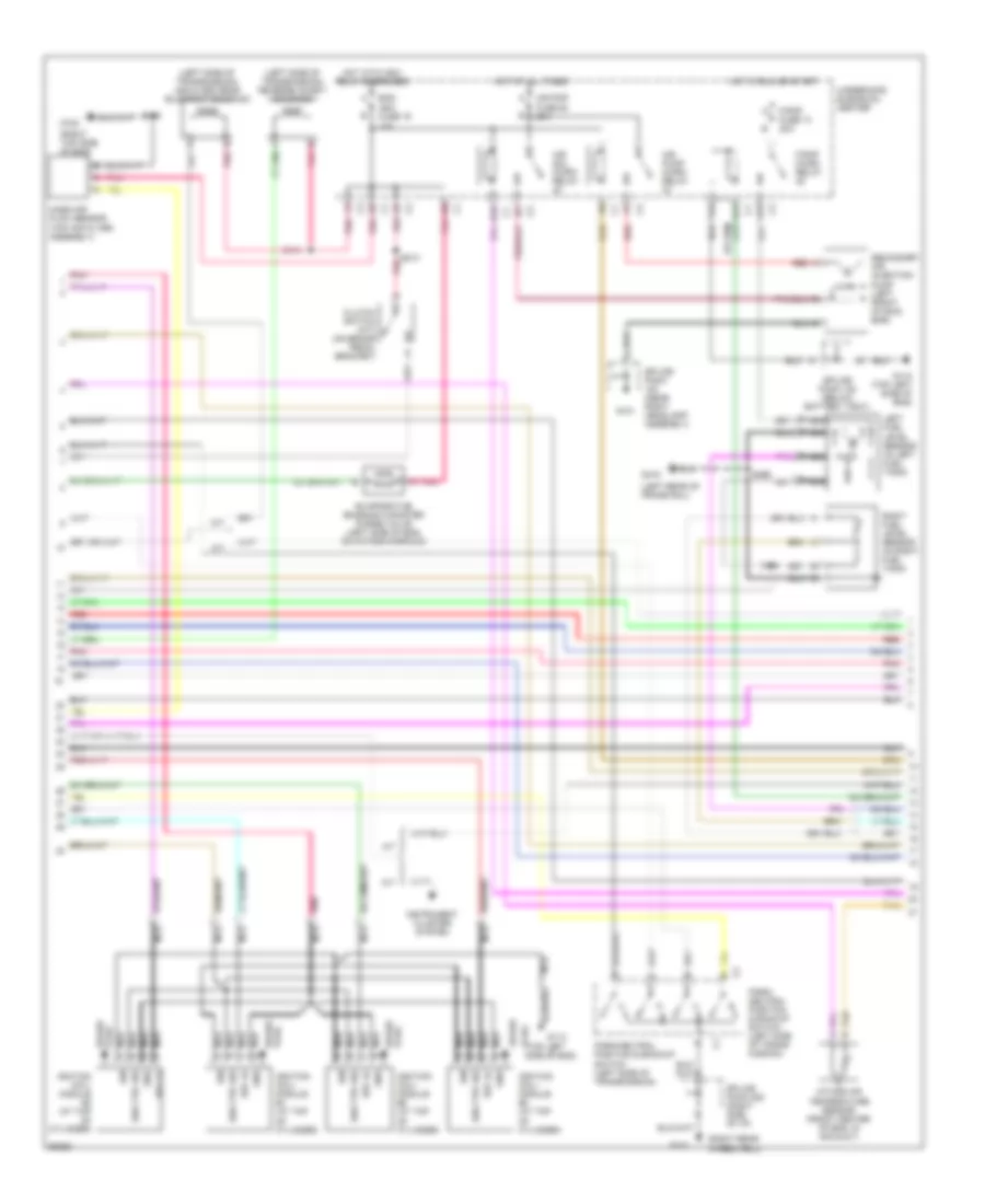
5.7L (VIN G), Engine Performance Wiring Diagrams (2 of 4) for Chevrolet Corvette 1997
 https://portal-diagnostov.com/license.html
Automotive Electricians Portal FZCO
Automotive Electricians Portal FZCO
https://portal-diagnostov.com/license.html
https://portal-diagnostov.com/license.html
Automotive Electricians Portal FZCO
Automotive Electricians Portal FZCOList of elements for 5.7L (VIN G), Engine Performance Wiring Diagrams (2 of 4) for Chevrolet Corvette 1997:
- (left rear of frame rail)
- (left side of transmission) 2nd & 3rd gear blockout solenoid
- (left side of transmission) reverse inhibit solenoid
- (right rear wheelwell)
- (right top side of eng)
- (top left plug side of eng)
- 10a
- A/t
- A12
- Air pmp fuse 50 20a
- Air pump micro relay
- Air sol micro relay
- B pnk
- Clutch switch (m/t) (on brake pedal bracket)
- D10
- E12
- Eng ign1 fuse 19
- Evaporative emission canister purge valve (left side of eng, on intake manifold)
- F/pmp fuse 13 20a
- F/pmp micro relay
- F12
- G101
- G103
- G112
- G112 (top left side of eng)
- G120
- G416
- Gnd
- Hot at all times
- Hot in run or start
- Hot with ign1 relay energized
- Ign
- Ign ctrl sig
- Ignition coil/ module #2 (at top of cylinder)
- Ignition coil/ module #4 (at top of cylinder)
- Ignition coil/ module #6 (at top of cylinder)
- Ignition coil/ module #8 (at top of cylinder)
- Instrument cluster system
- Left fuel level sensor (in left fuel tank)
- M/t
- Mass air flow sensor (top air filter assembly)
- Nca
- Park/ neutral position & backup switch (left side of trans- mission)
- Park/neutral position & backup switch (left side of transmission)
- Plug spark
- Pnk
- Red
- Red a
- Ref lo
- Right fuel level sensor (in right fuel tank)
- S120
- S213 pnk
- S414
- S444
- S466
- Secondary air injection pump (left front of skid bar)
- Spark
- Spark plug
- Splice pack (near right headlamp assembly)
- Splice pack 122 (below battery tray)
- Splice pack 208 (right side of i/p)
- Tan
- Underhood elecrical center
- Z intake air temperature sensor (front center of eng, in air duct)
5.7L (VIN G), Engine Performance Wiring Diagrams (3 of 4) for Chevrolet Corvette 1997
 https://portal-diagnostov.com/license.html
Automotive Electricians Portal FZCO
Automotive Electricians Portal FZCO
https://portal-diagnostov.com/license.html
https://portal-diagnostov.com/license.html
Automotive Electricians Portal FZCO
Automotive Electricians Portal FZCOList of elements for 5.7L (VIN G), Engine Performance Wiring Diagrams (3 of 4) for Chevrolet Corvette 1997:
- (base of accelerator) accelerator pedal position sensor
- (left side of throttle body) throttle actuator motor
- (mil)
- (on throttle body) throttle position sensor
- (right top side of eng)
- 1-2 shift solenoid
- 2-3 shift solenoid
- 3-2 shift solenoid
- Act ctrl #1
- Act ctrl #2
- App #1 5v ref
- App #1 sig
- App #2 5v ref
- App #2 gnd
- App #2 sig
- App #3 5v ref
- App #3 gnd
- App #3 sig
- Automatic trans- mission
- Automatic transmission fluid pressure
- Automatic transmission fluid temp sensor
- B16
- Cruise control system
- D2 sw
- D3 sw
- D4 sw
- Eng ign 1 fuse 19 15a
- Exterior lights system
- Fuse 8 20a b
- G120
- Gnd
- Hot at all times
- Hot with ign relay energized (in run or start)
- Ign
- Instrument cluster
- Instrument panel electrical center
- Lo sw
- Malfunction indicator lamp
- Manual valve position switch
- On/off sig
- Pessure control solenoid valve
- Pnk
- Pp #1 gnd
- Red
- Res/acc sig
- Rev sw
- S120
- S213 s213
- Set/coast sig
- Stop sw sig
- Stoplamp switch (under brake pedal) c2
- Stp haz a
- Tac serl data
- Tan
- Tcc pwm solenoid
- Tcc solenoid
- Throt cont fuse 17 15a
- Throttle actuator control module (behind right front wheel well)
- Torque converter clutch switch (under brake pedal)
- Tps #1 5v ref
- Tps #1 sig
- Tps #2 5v ref
- Tps #2 gnd
- Tps #2 sig
- Underhood electrical center
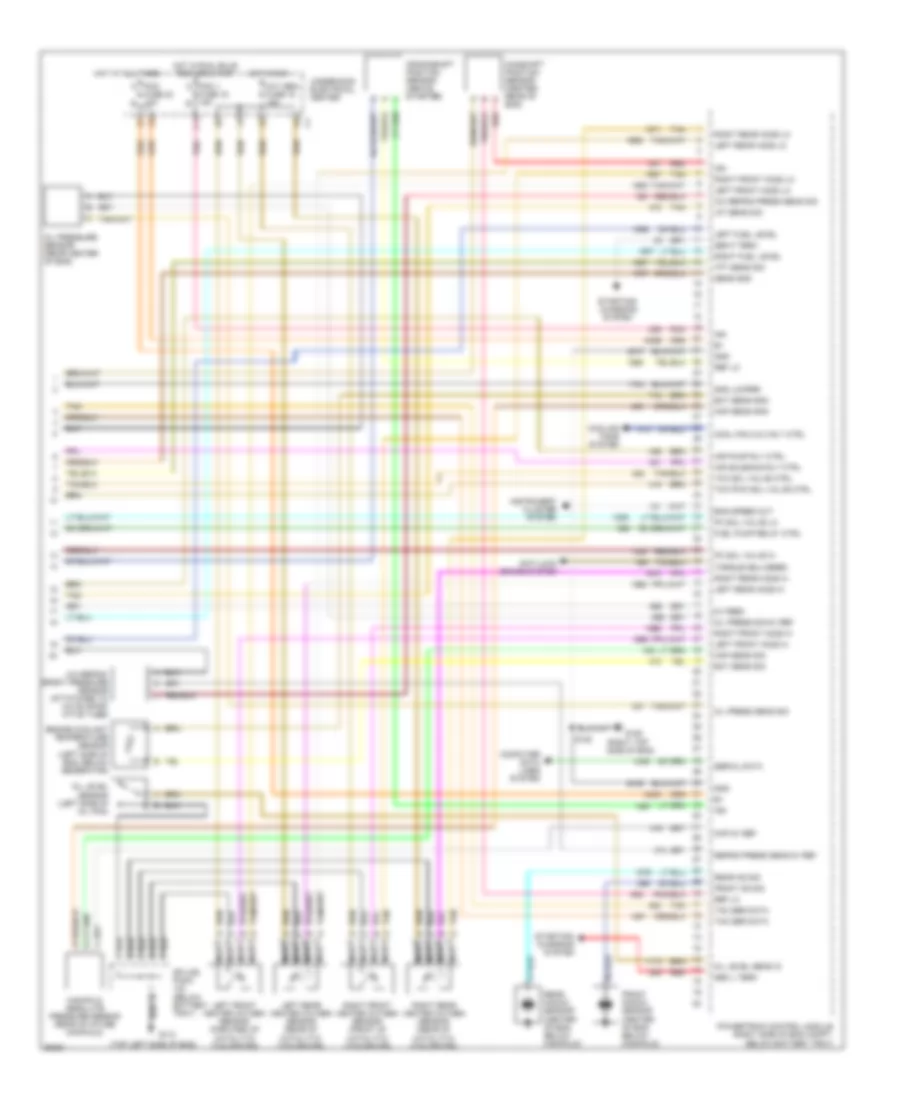
5.7L (VIN G), Engine Performance Wiring Diagrams (4 of 4) for Chevrolet Corvette 1997
 https://portal-diagnostov.com/license.html
Automotive Electricians Portal FZCO
Automotive Electricians Portal FZCO
https://portal-diagnostov.com/license.html
https://portal-diagnostov.com/license.html
Automotive Electricians Portal FZCO
Automotive Electricians Portal FZCOList of elements for 5.7L (VIN G), Engine Performance Wiring Diagrams (4 of 4) for Chevrolet Corvette 1997:
- (right top side of eng)
- (top left side of eng)
- 340b
- 340c
- 451e
- 451f
- 5v feed
- A/c refrig press sens sig
- A/c refrig- erant pressure sensor (attatched to a/c evapor- ative tube)
- Air pump rly ctrl
- Air solenoid rly ctrl
- Anti-lock brake system
- Camshaft position sensor (center rear of eng)
- Computer data lines system
- Cool fan 2 & 3 rly ctrl
- Cooling fans system
- Crankshaft position sensor (above starter)
- Ect sens gnd
- Ect sens sig
- Eng speed out
- Engine coolant temperature sensor (left side of eng, below generator)
- F11
- Front knock sensor (center of eng, below manifold)
- Front ks sig
- Fuel pump relay ctrl
- Fuse 16 15a b
- Fuse 23 10a b
- G106
- G112
- Gen f term
- Gen l term
- Gnd
- Gnd jumper
- Hot at all times
- Hot in run
- Hot in run, bulb test or start
- Iat sens sig
- Ign
- Instrument cluster system
- Left front heated oxygen sensor (forward of catalytic converter)
- Left front ho2s hi
- Left front ho2s lo
- Left fuel level
- Left rear heated oxygen sensor (rear of catalytic converter)
- Left rear ho2s hi
- Left rear ho2s lo
- Manifold absolute pressure sensor (rear of intake manifold)
- Map 5v ref
- Map sens gnd
- Map sens sig
- Nca
- Oil level sens in
- Oil level sensor (left side of oil pan)
- Oil press sens sig
- Oil press sig 5v ref
- Oil pressure sensor (rear center of eng)
- Oxy sen fuse 15 15a
- Pc sol valve hi
- Pc sol valve lo
- Pcm 1 a
- Pcm a
- Pnk
- Powertrain control module (right side of eng compt, below battery tray)
- Rear knock sensor (center of eng, below manifold)
- Rear ks sig
- Red
- Ref lo
- Refrig press sens 5v ref
- Right front heated oxygen sensor (front of catalytic converter)
- Right front ho2s hi
- Right front ho2s lo
- Right fuel level
- Right rear heated oxygen sensor (rear of catalytic converter)
- Right rear ho2s hi
- Right rear ho2s lo
- S120
- Sens gnd
- Serial data
- Splice pack (below battery tray)
- Starting/ charging
- Starting/ charging system
- System
- Tac ser data
- Tan
- Tcc pwm sol valve ctrl
- Tcc sol valve ctrl
- Tft sens sig
- Torque delivered
- Underhood electrical center
EXTERIOR LIGHTS
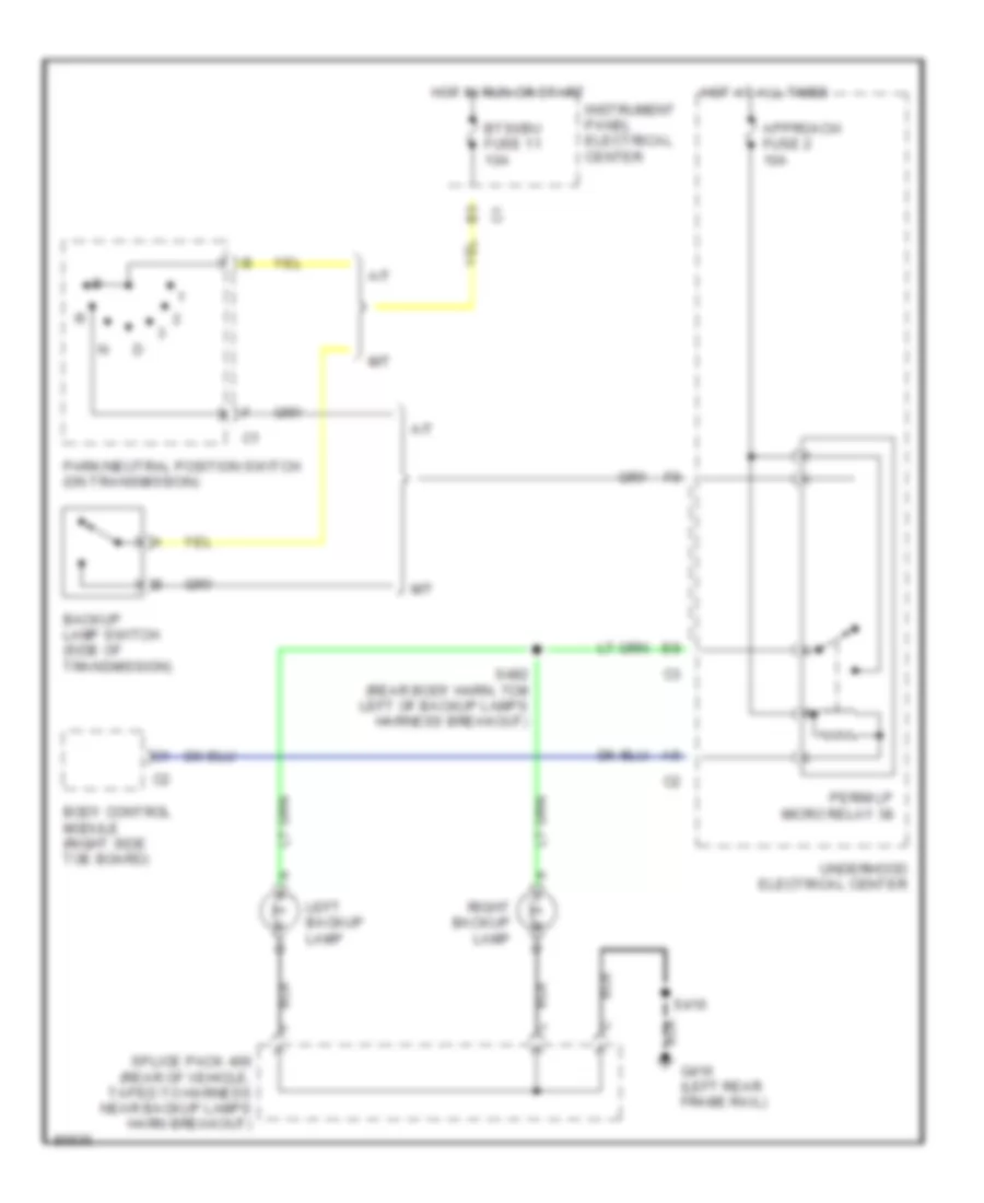
Back-up Lamps Wiring Diagram for Chevrolet Corvette 1997
 https://portal-diagnostov.com/license.html
Automotive Electricians Portal FZCO
Automotive Electricians Portal FZCO
https://portal-diagnostov.com/license.html
https://portal-diagnostov.com/license.html
Automotive Electricians Portal FZCO
Automotive Electricians Portal FZCOList of elements for Back-up Lamps Wiring Diagram for Chevrolet Corvette 1997:
- A/t
- Approach fuse 2 10a
- Backup lamp switch (side of transmission)
- Body control module (right side toe board)
- Btsi/bu fuse 11 10a
- G416 (left rear frame rail)
- Hot at all times
- Hot in run or start
- Instrument panel electrical center
- Left backup lamp
- M/t
- Park/neutral position switch (on transmission)
- Perim lp micro relay 38
- Right backup lamp
- S416
- S482 (rear body harn, 7cm left of backup lamps harness breakout)
- Splice pack 400 (rear of vehicle, taped to harness near backup lamps harn breakout)
- Underhood electrical center
Exterior Lamps Wiring Diagram (1 of 2) for Chevrolet Corvette 1997
 https://portal-diagnostov.com/license.html
Automotive Electricians Portal FZCO
Automotive Electricians Portal FZCO
https://portal-diagnostov.com/license.html
https://portal-diagnostov.com/license.html
Automotive Electricians Portal FZCO
Automotive Electricians Portal FZCOList of elements for Exterior Lamps Wiring Diagram (1 of 2) for Chevrolet Corvette 1997:
- (i/p harness, 30cm from dic connector) s211
- A15
- A16
- Ambient light sensor (top of dashboard)
- Approach fuse 2 10a
- B12
- Battery (b+)
- Body control module (right floor board)
- Brake warn
- Brake wrn lp out
- C12
- Cr cont fuse 20 10a
- D11
- D12
- D16
- Daytime running lamps (drl) control module (behind cluster, under left dash assembly)
- Drl left relay
- Drl right relay
- E12
- Ext lites out
- F12
- G101
- G200
- Ground
- Hazard sw
- Head
- Headlamp switch
- Hot at all times
- Hot in run or start
- Ignition
- Instrument cluster
- Instrument panel electrical center
- Left front park/ turn lamp
- Left relay ctrl
- Left side marker lamp b
- Left turn sig
- Lft drl ctrl
- Lft turn in
- Light sensor
- Nca
- Off
- Park
- Park brake switch (park brake handle assy)
- Pkt/lp fuse 6 10a
- Pnk
- Prk brk switch
- Right front park/ turn lamp
- Right relay ctrl
- Right side marker lamp
- Rt drl ctrl
- Rt turn in
- Rt turn sig
- S205 (i/p harness, 4cm right of radio module)
- S209 (i/p harn, 20cm from dic harness connector)
- Splice pack 100 (rear of right front wheelwell)
- Splice pack 102 (under right headlamp, taped to harness)
- Splice pack 201 (left kick panel)
- Turn signal switch
- Underhood electrical center
Exterior Lamps Wiring Diagram (2 of 2) for Chevrolet Corvette 1997
 https://portal-diagnostov.com/license.html
Automotive Electricians Portal FZCO
Automotive Electricians Portal FZCO
https://portal-diagnostov.com/license.html
https://portal-diagnostov.com/license.html
Automotive Electricians Portal FZCO
Automotive Electricians Portal FZCOList of elements for Exterior Lamps Wiring Diagram (2 of 2) for Chevrolet Corvette 1997:
- Anti-lock brakes system
- Center high mount stop lamp (chmsl)
- Flasher
- G200
- G416 (left rear frame rail)
- Haz/tsig fuse 15 20a
- Hazard switch
- Hot at all times
- Hot in run or start
- Instrument panel electrical center
- Left side marker lamp b
- Left tail/ stop/ turn lamps
- License lamps
- Pnk
- Right side marker lamp
- Right tail/ stop/ turn lamps
- S416
- S420 (trans harness, 20cm right of ground breakout)
- S481 (rear body harn, 7cm right of left tail/stop lamp harness breakout)
- S484 (rear body harness, 7cm right of back- up lamps breakout)
- S492 (rear body harn, 5cm left of left tail/stop lamp harn breakout)
- Splice pack 201 (left kick panel)
- Splice pack 400 (rear of vehicle, taped to harness near backup lamps)
- Stop/haz fuse 8 20a
- Stoplamp switch
- Underhood electrical center
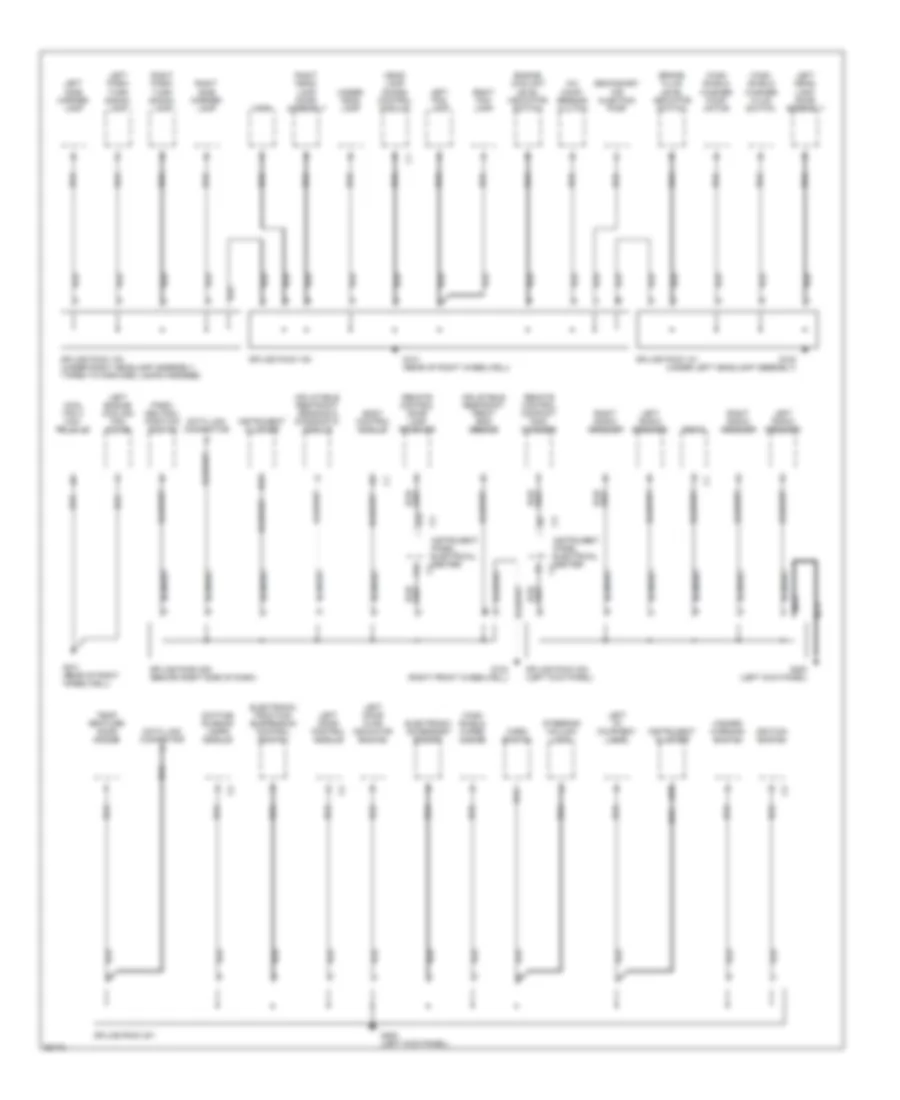
GROUND DISTRIBUTION
Ground Distribution Wiring Diagram (1 of 3) for Chevrolet Corvette 1997
 https://portal-diagnostov.com/license.html
Automotive Electricians Portal FZCO
Automotive Electricians Portal FZCO
https://portal-diagnostov.com/license.html
https://portal-diagnostov.com/license.html
Automotive Electricians Portal FZCO
Automotive Electricians Portal FZCOList of elements for Ground Distribution Wiring Diagram (1 of 3) for Chevrolet Corvette 1997:
- A/c comp- ressor clutch
- A12
- B13
- B15
- Body control module
- Brake fluid level indicator switch
- Cool fan 3 mini- relay 40
- Data link connector
- Daytime running lamps module
- Electronic accessory socket
- Electronic traction/ suspension control switch
- Engine coolant level indicator switch
- F12
- G100 (under left headlamp assembly)
- G101 (rear of right wheelwell)
- G103 (right front wheelwell)
- G200 (left kick panel)
- Hazard warning switch
- Head- lamp doors control module
- Horn
- Horn switch
- Ignition switch
- Inflatable restraint front end sensor
- Inflatable restraint sensing & diagnostic module
- Instrument cluster
- Instrument panel electrical center
- Left door ajar indicator switch
- Left door control module
- Left engine cooling fan motor
- Left fog lamp
- Left head- lamp door assembly
- Left i/p courtesy lamp
- Left park/ turn siganl lamp
- Left radio speaker
- Left side marker lamp
- Nca
- Park/ neutral position switch
- Radio
- Remote control compact disc changer
- Remote control door lock receiver
- Right fog lamp
- Right head- lamp door assembly
- Right park/ turn siganl lamp
- Right radio speaker
- Right side marker lamp
- Secondary air injection pump
- Splice pack 100
- Splice pack 101
- Splice pack 102 (under right headlamp assembly, taped to forward lamps harness)
- Splice pack 201
- Splice pack 203 (left kick panel)
- Splice pack 208 (behind right side of dash)
- Steering column lock
- Temp- erature door motor
- Under- hood lamp
- Wind- shield washer fluid switch
- Wind- shield washer pump motor
- Wind- shield wiper motor
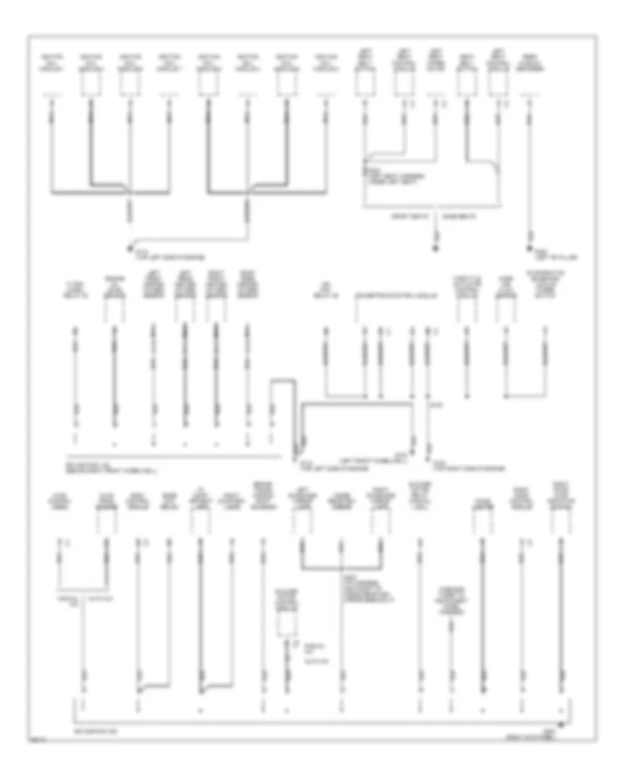
Ground Distribution Wiring Diagram (2 of 3) for Chevrolet Corvette 1997
 https://portal-diagnostov.com/license.html
Automotive Electricians Portal FZCO
Automotive Electricians Portal FZCO
https://portal-diagnostov.com/license.html
https://portal-diagnostov.com/license.html
Automotive Electricians Portal FZCO
Automotive Electricians Portal FZCOList of elements for Ground Distribution Wiring Diagram (2 of 3) for Chevrolet Corvette 1997:
- Auto a/c
- Base seats
- Blower motor control module
- Blower motor relay (manual a/c)
- Body control module
- Bose mini- relay
- Brake/ trans- mission shift solenoid
- Cigar lighter
- Engine oil level sensor
- Evaporative emissions vacuum purge switch
- F/ pmp micro- relay 35
- G112 (top left side of engine)
- G120 (top right side of engine)
- G203 (right kick panel)
- G308 (left "b" pillar)
- Hvac control head
- Hvac prog- rammer
- I/p comp- artment lamp
- Ign mini- relay 39
- Ignition coil module 1
- Ignition coil module 2
- Ignition coil module 3
- Ignition coil module 4
- Ignition coil module 5
- Ignition coil module 6
- Ignition coil module 7
- Ignition coil module 8
- Inside rearview mirror
- Left front heated oxygen sensor
- Left rear heated oxygen sensor
- Left seat belt switch
- Left seat control module
- Left seat upper motor
- Left sunshade mirror lamp
- Manual a/c
- Mass air flow sensor
- Nca
- Powertrain control module
- Rear window defogger
- Right courtesy lamp
- Right door ajar indicator switch
- Right door control module
- Right front heated oxygen sensor
- Right rear heated oxygen sensor
- Right sunshade mirror lamp
- S120
- S202 (i/p harness, 35cm right of inside rearview mirror breakout)
- S303 (left seat harness, under left seat)
- Seat belt switch
- Splice pack 122 (behind right front wheelwell)
- Splice pack 202
- Sport seats
- Throttle actuator control module
- Wire end taped to instrument panel harness
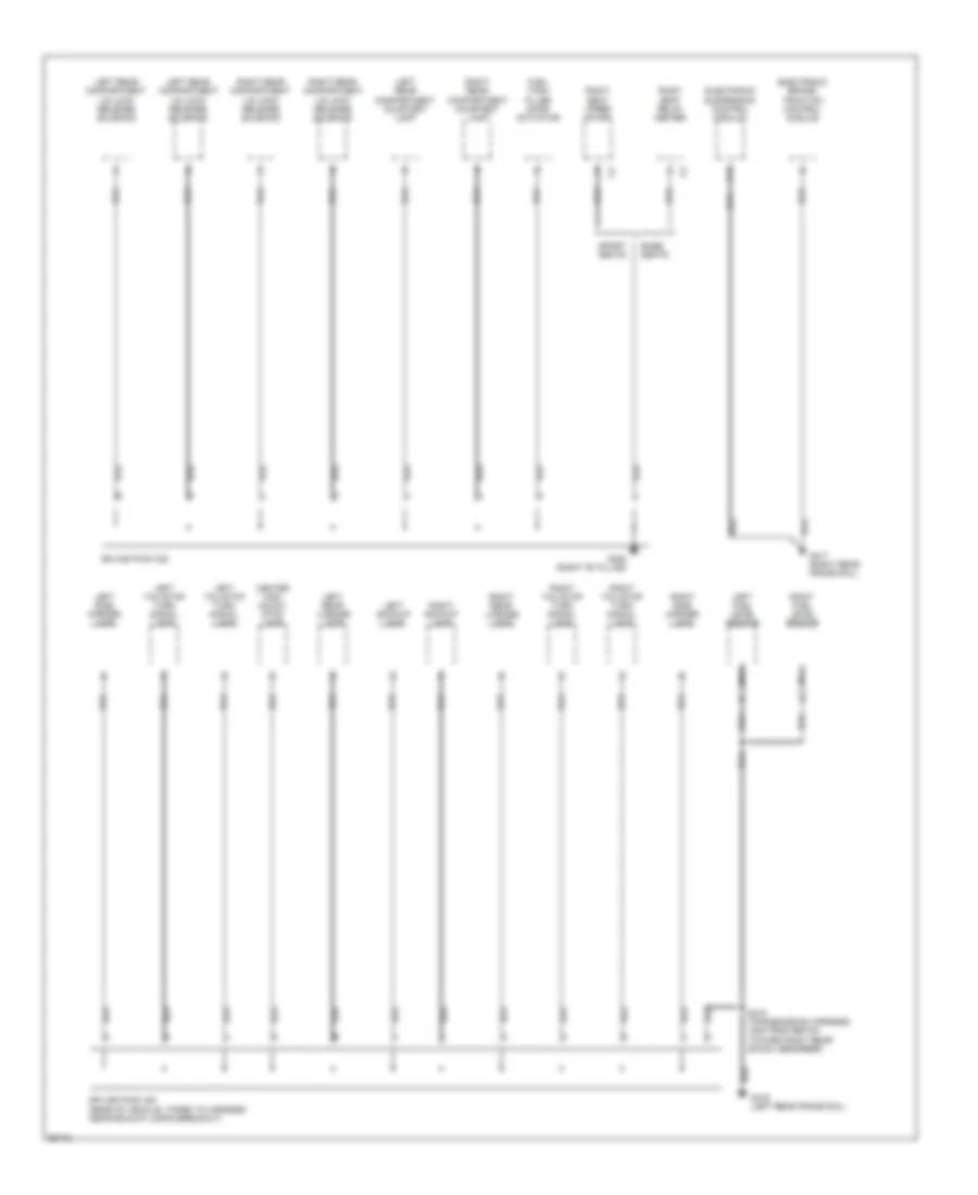
Ground Distribution Wiring Diagram (3 of 3) for Chevrolet Corvette 1997
 https://portal-diagnostov.com/license.html
Automotive Electricians Portal FZCO
Automotive Electricians Portal FZCO
https://portal-diagnostov.com/license.html
https://portal-diagnostov.com/license.html
Automotive Electricians Portal FZCO
Automotive Electricians Portal FZCOList of elements for Ground Distribution Wiring Diagram (3 of 3) for Chevrolet Corvette 1997:
- Base seats
- C16
- Center high mount stop lamp
- Electronic brake/ traction control module
- Electronic suspension control module
- Fuel tank filler door actuator
- G305 (right "b" pillar)
- G416 (left rear frame rail)
- G417 (right rear frame rail)
- Left backup lamp
- Left fuel level sensor
- Left rear compartment courtesy lamp
- Left rear compartment lid lock release solenoid
- Left rear license lamp
- Left side marker lamp
- Left tail/stop turn signal lamp
- Nca
- Right backup lamp
- Right fuel level sensor
- Right rear compartment courtesy lamp
- Right rear compartment lid lock release solenoid
- Right rear license lamp
- Right seat relay center
- Right seat upper motor
- Right side marker lamp
- Right tail/stop turn signal lamp
- S416 (transmission harness, 16cm from ebtcm toward right rear shock absorber)
- Splice pack 302
- Splice pack 400 (rear of vehicle, taped to harness near backup lamps breakout)
- Sport seats
HEADLIGHTS
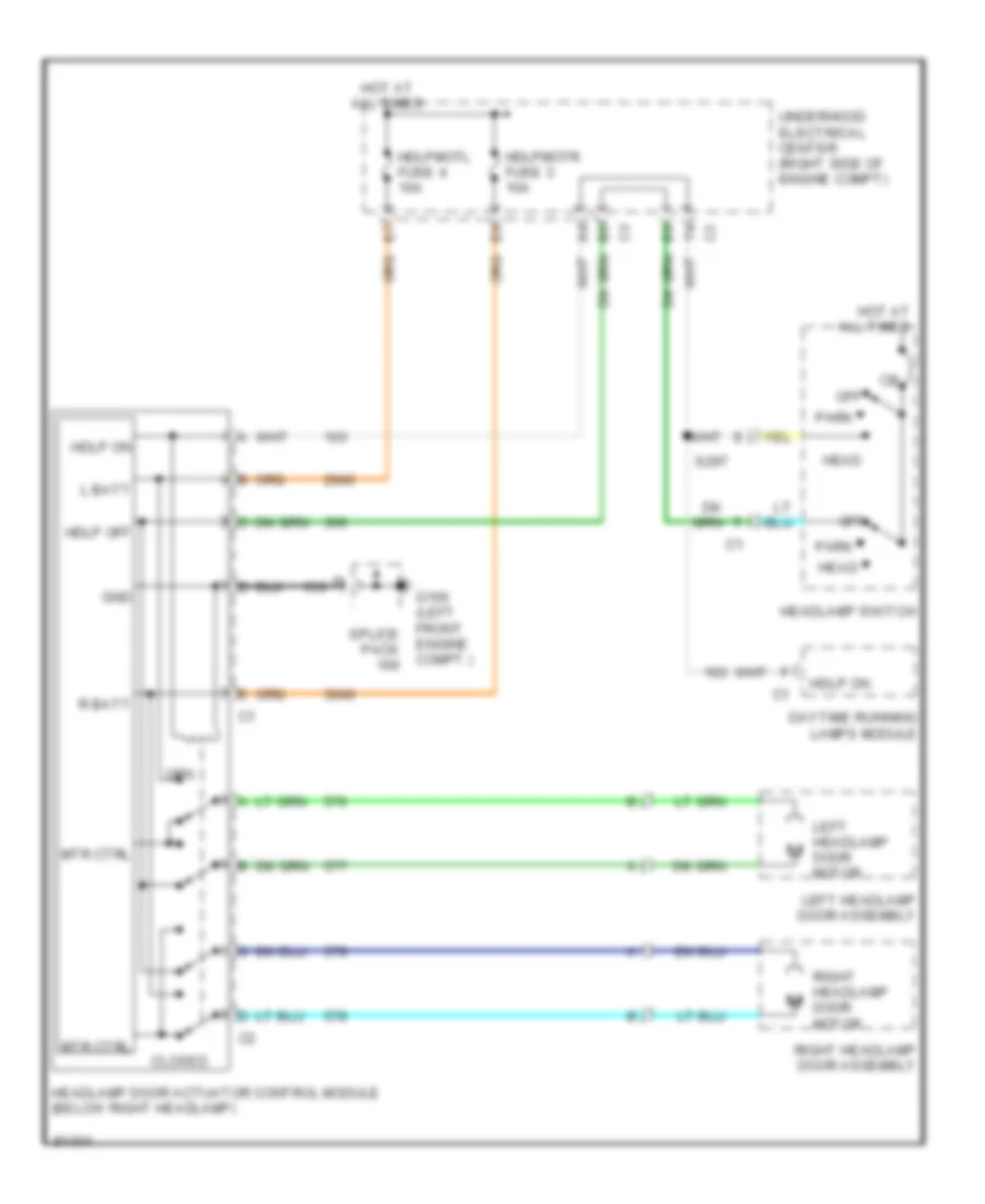
Headlamp Doors Wiring Diagram for Chevrolet Corvette 1997
 https://portal-diagnostov.com/license.html
Automotive Electricians Portal FZCO
Automotive Electricians Portal FZCO
https://portal-diagnostov.com/license.html
https://portal-diagnostov.com/license.html
Automotive Electricians Portal FZCO
Automotive Electricians Portal FZCOList of elements for Headlamp Doors Wiring Diagram for Chevrolet Corvette 1997:
- B6 c3
- Closed
- Daytime running lamps module
- F4 c2
- G100 (left front engine compt.)
- Gnd
- Hdlp off
- Hdlp on
- Hdlpmotl fuse 4 10a
- Hdlpmotr fuse 3 10a
- Head
- Headlamp door actuator control module (below right headlamp)
- Headlamp switch
- Hot at all times
- L batt
- Left headlamp door assembly
- Left headlamp door motor
- Mtr ctrl
- Off
- Opn
- Park
- R batt
- Right headlamp door assembly
- Right headlamp door motor
- S297
- Splice pack
- Underhood electrical center (right side of engine compt)
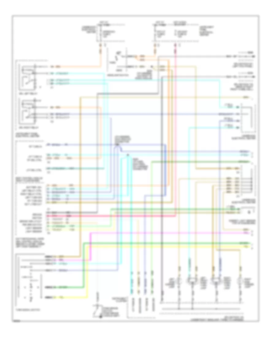
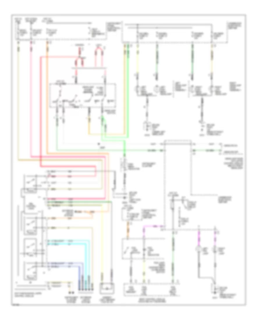
Headlamps/Fog Lamps Wiring Diagram for Chevrolet Corvette 1997
 https://portal-diagnostov.com/license.html
Automotive Electricians Portal FZCO
Automotive Electricians Portal FZCO
https://portal-diagnostov.com/license.html
https://portal-diagnostov.com/license.html
Automotive Electricians Portal FZCO
Automotive Electricians Portal FZCOList of elements for Headlamps/Fog Lamps Wiring Diagram for Chevrolet Corvette 1997:
- A c4 red
- A10
- Ambient light sensor (top of i/p)
- B15
- Bcmi3 fuse 6 10a
- Body control module (mounted on toe board)
- C10
- C2 d
- C4 c3
- C4 red
- Canada
- Cr cont fuse 20 10a
- D10 c2
- D2 c2
- Daytime running lamps control module
- Drl control logic
- E1 c2
- E4 c3
- E6 c1
- Exterior lights system
- F/tnk dr fuse 32 15a
- F12 c1
- Flash
- Flash -to- pass switch
- Fog lamp ind ctrl
- Fog lamp on indicator
- Fog lamp relay ctrl
- Fog lamp request
- Fog lamp switch
- Fog lamp/ rear compartment lid release switch
- Fog lp fuse 6 10a
- Fog lp micro- relay
- G100
- G101
- G200
- Hdhibml fuse 12 10a
- Hdhibmr fuse 9 10a
- Hdlobml fuse 10 10a
- Hdlobmr fuse 8 10a
- Hdlp circuit breaker 53 20a
- Head
- Headlamp dimmer switch
- Headlamp door actuator control module (below right headlamp)
- Headlamp switch
- Headlps off
- Headlps on
- High
- High beam indicator
- Hot at all times
- Hot in run
- Hot in run or start
- Instrument cluster
- Instrument cluster system
- Instrument panel electrical center
- L tan
- Left fog lamp
- Left headlamp door assembly
- Left high beam headlamp
- Left low beam headlamp
- Low
- Nca
- Off
- Park
- Pk t/lp fuse 6 10a
- Pnk
- Red
- Right fog lamp
- Right headlamp door assembly
- Right high beam headlamp
- Right low beam headlamp
- S207
- S297
- Splice pack (left kick panel)
- Splice pack (rear of right wheelwell)
- Splice pack (under left headlamp)
- Tan
- U.s.a. a
- Underhood electrical center
HORN
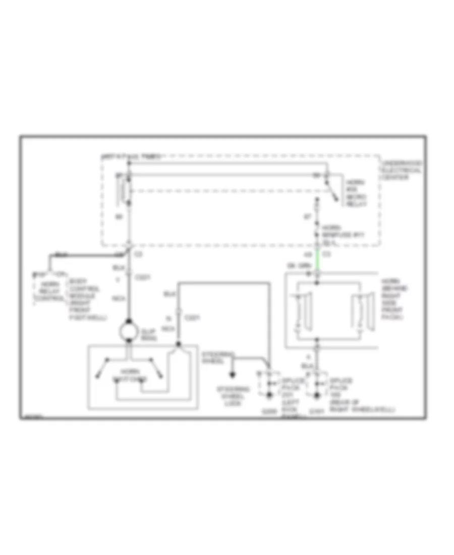
Horn Wiring Diagram for Chevrolet Corvette 1997
 https://portal-diagnostov.com/license.html
Automotive Electricians Portal FZCO
Automotive Electricians Portal FZCO
https://portal-diagnostov.com/license.html
https://portal-diagnostov.com/license.html
Automotive Electricians Portal FZCO
Automotive Electricians Portal FZCOList of elements for Horn Wiring Diagram for Chevrolet Corvette 1997:
- B10
- Body control module (right front footwell)
- C221
- G101
- G200
- Horn #36 micro relay
- Horn (behind right side front facia)
- Horn minifuse #11 20 a
- Horn relay control
- Horn switches
- Hot at all times
- Nca
- Slip ring
- Splice pack (left kick panel)
- Splice pack (rear of right wheelwell)
- Steering wheel
- Steering wheel lock
- Underhood electrical center
INSTRUMENT CLUSTER
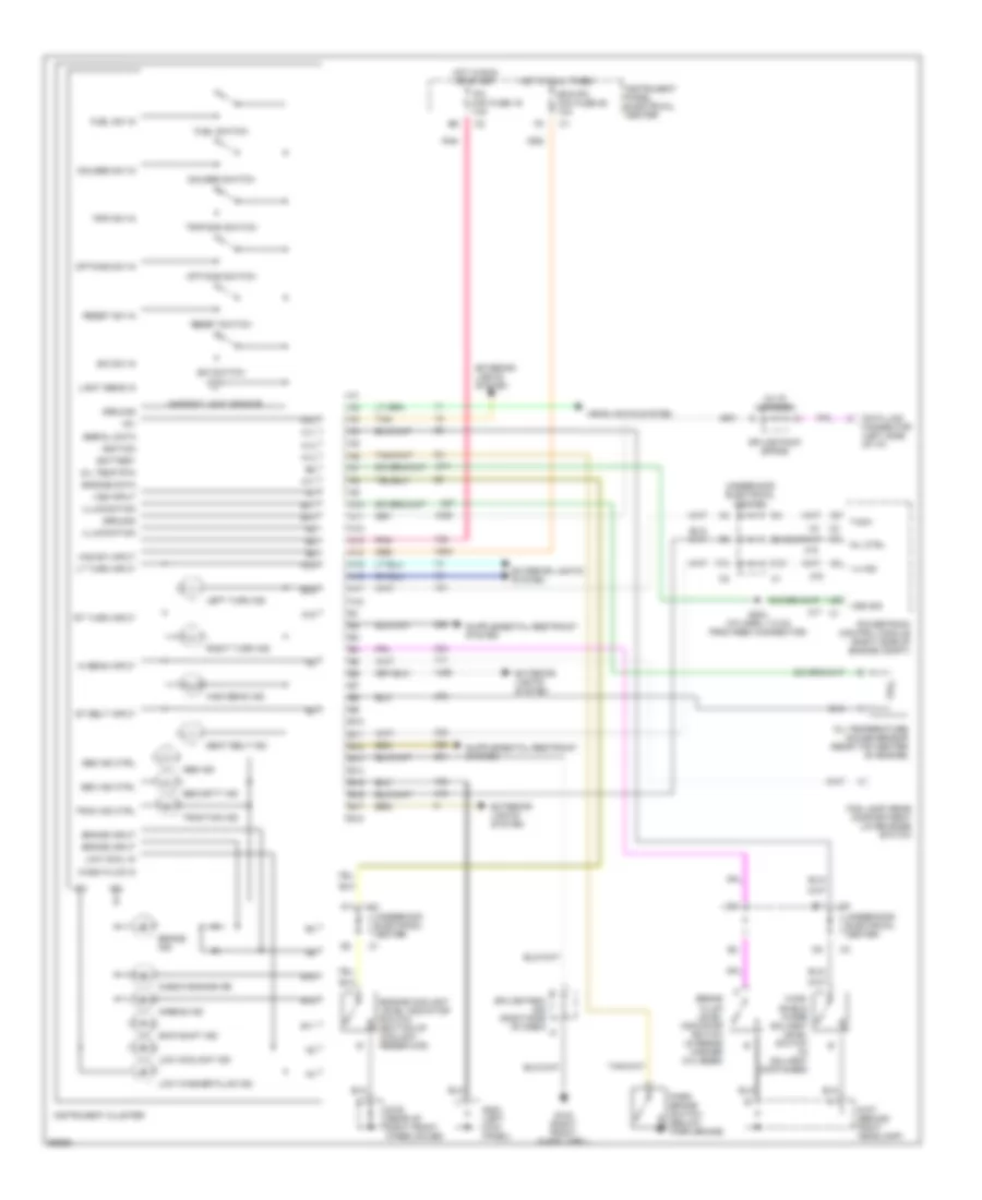
Instrument Cluster Wiring Diagram for Chevrolet Corvette 1997
 https://portal-diagnostov.com/license.html
Automotive Electricians Portal FZCO
Automotive Electricians Portal FZCO
https://portal-diagnostov.com/license.html
https://portal-diagnostov.com/license.html
Automotive Electricians Portal FZCO
Automotive Electricians Portal FZCOList of elements for Instrument Cluster Wiring Diagram for Chevrolet Corvette 1997:
- (in i/p harness)
- +5v
- 1-4 ind
- A10
- A11
- A12
- A13
- A14
- A15
- A16
- A17
- A18
- Abs ind
- Abs ind ctrl
- Airbag ind
- Ambient light sensor
- B10
- B11
- B12
- B13
- B14
- B15
- B16
- B17
- B18
- Battery
- Bcm/ipc mini fuse 25 10a
- Brake ind
- Brake fluid level indicator switch (in brake master cylinder)
- Brake input
- C10
- Check engine ind
- Data link connector (left side of i/p)
- E/m sw in
- E/m switch
- Engine coolant level indicator switch (bottom of coolant reservoir)
- Engine data
- Exterior lights system
- F10
- Fog lamp/ rear compartment lid release switch
- Fuel sw in
- Fuel switch
- G103 (right front wheelweel)
- G105 (rear of right front wheelhouse)
- G107 (behind right headlamp)
- G200 (left kick panel)
- Gauges sw in
- Gauges switch
- Ground
- Haz sw input
- Headlights system
- Hi beam input
- High beam ind
- Hot at all times
- Hot in run or start
- Ign
- Ignition
- Illumination
- Instrument cluster
- Instrument panel electrical center
- Ipc mini fuse 19 10a
- Left turn ind
- Light sens in
- Low cool in
- Low coolant ind
- Low washer fluid ind
- Lt turn input
- Mil ctrl
- Oil temp rtn
- Oil temperature gauge sensor (rear top center of engine)
- Options sw in
- Options switch
- Park brake switch (below park brake)
- Pnk
- Powertrain control module (right side of engine compt)
- Reset sw in
- Reset switch
- Right turn ind
- Rt turn input
- S204 (i/p harn, 7.5 cm from fbec connector)
- Seat belt ind
- Sec ind ctrl
- Security ind
- Serial data
- Skip shift ind
- Splice pack (right side of dash)
- Splice pack (sp206)
- St belt input
- Tach
- Tan
- Trac ind ctrl
- Traction ind
- Trip sw in
- Trip/odo switch
- Underhood electrical center
- Vss input
- Vss sig
- Wash fluid in
- Wind- shield wiper solvent level switch (in solvent container)
INTERIOR LIGHTS
Courtesy Lamps Wiring Diagram for Chevrolet Corvette 1997
 https://portal-diagnostov.com/license.html
Automotive Electricians Portal FZCO
Automotive Electricians Portal FZCO
https://portal-diagnostov.com/license.html
https://portal-diagnostov.com/license.html
Automotive Electricians Portal FZCO
Automotive Electricians Portal FZCOList of elements for Courtesy Lamps Wiring Diagram for Chevrolet Corvette 1997:
- A12
- B12
- Body control module (bcm) (mounted on toe board)
- C/l aldl mini fuse 29 10a
- C2 c11
- C2 c12
- Ctsy lp micro relay 42
- F3 c2
- G101 (rear of right wheelwell)
- G200 (left kick panel)
- G203 (right kick panel)
- G305 (right "b" pillar)
- Hot at all times
- I/p compartment lamp
- Inadv load mod
- Inadv rly cntrl
- Inside rearview mirror
- Instrument panel electrical center
- Left i/p courtesy lamp
- Left rear compartment courtesy lamp
- Left vanity mirror lamp
- Monitored ld micro relay 43
- Monitored ld mini fuse 2 10a
- Relay cntrl
- Right i/p courtesy lamp
- Right rear compartment courtesy lamp
- Right vanity mirror lamp
- S200 (i/p harn, near inside rearview mirror breakout)
- S202
- S309
- Splice pack
- Underhood electrical center
- Underhood lamp
Instrument Illumination Wiring Diagram for Chevrolet Corvette 1997
 https://portal-diagnostov.com/license.html
Automotive Electricians Portal FZCO
Automotive Electricians Portal FZCO
https://portal-diagnostov.com/license.html
https://portal-diagnostov.com/license.html
Automotive Electricians Portal FZCO
Automotive Electricians Portal FZCOList of elements for Instrument Illumination Wiring Diagram for Chevrolet Corvette 1997:
- (c60)
- (cj2)
- (cj2) (c60)
- A11
- B15
- B17
- Body control module (bcm) (mounted on toe board)
- Brake transmission shift lock control solenoid
- C16 j
- C211
- C60
- Cj2
- D11
- D12
- Data link connector (dlc)
- Dimming cntrl
- Dimming level
- Electronic traction suspension control switch
- F11
- Fog lamp/ rear compartment lid release switch
- G200 (left kick panel)
- G203 (right kick panel)
- Head
- Head lamp switch
- Headlamps system (drl module)
- Hot at all times
- Hvac control head (w/ c60) hvac programmer module (w cj2)
- Inside rearview mirror
- Instrument cluster
- Instrument panel electrical center
- Left door control module (dcm) (inside left door)
- Left door switch
- Nca
- Off
- Park
- Pkt/lp mini fuse 6 10a
- Prndl
- Radio
- Right door control module (dcm) (inside right door)
- Right door switch
- S202
- S208 (i/p harn, near bcm breakout)
- Serial data
- Serial data dimming cntrl
- Solid state
- Splice pack
- Tan
- Underhood electrical center
MEMORY SYSTEMS
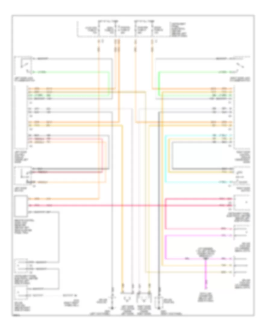
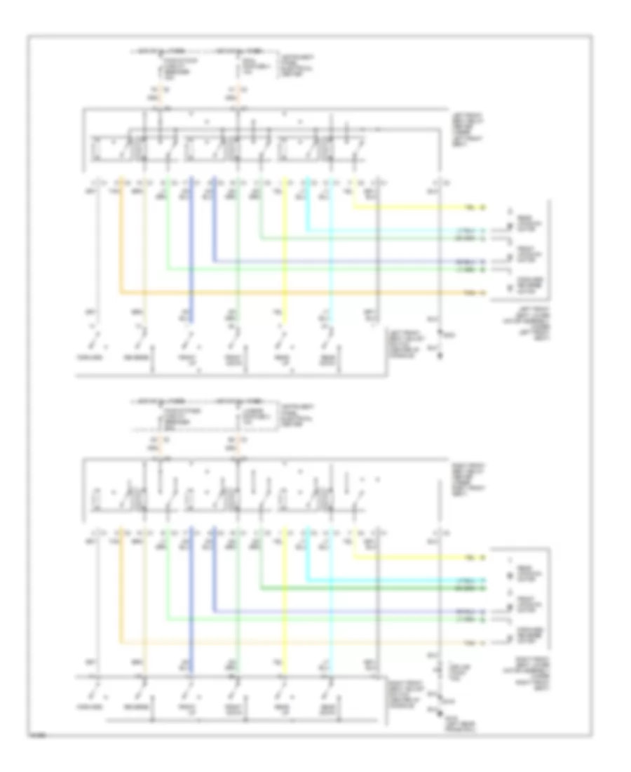
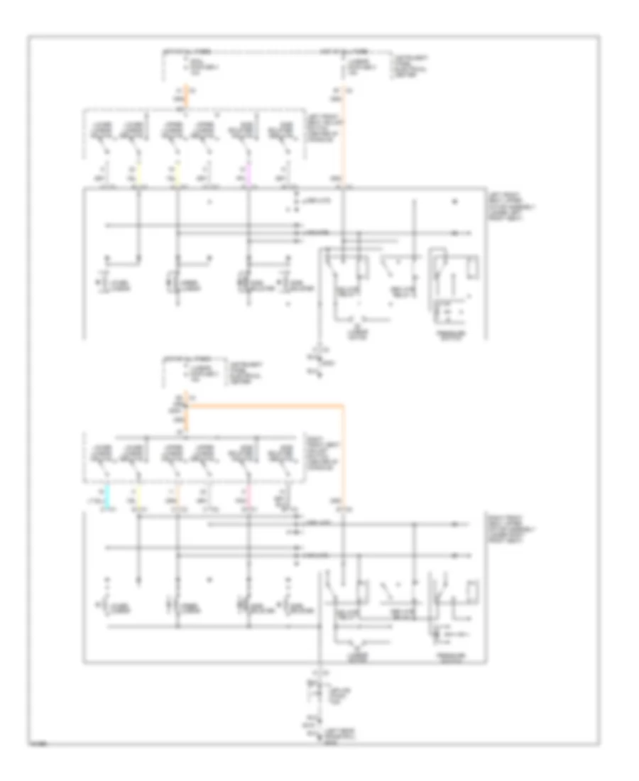
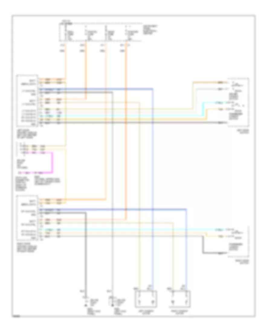
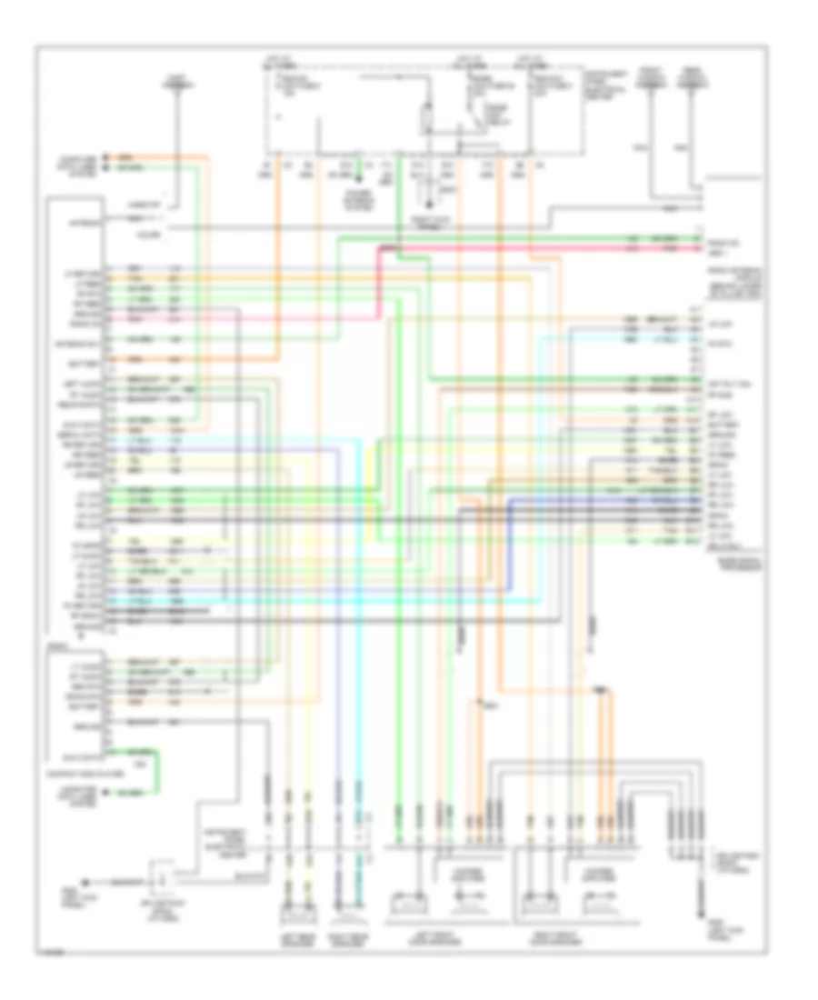
Memory Seat/Mirrors Wiring Diagram for Chevrolet Corvette 1997
 https://portal-diagnostov.com/license.html
Automotive Electricians Portal FZCO
Automotive Electricians Portal FZCO
https://portal-diagnostov.com/license.html
https://portal-diagnostov.com/license.html
Automotive Electricians Portal FZCO
Automotive Electricians Portal FZCOList of elements for Memory Seat/Mirrors Wiring Diagram for Chevrolet Corvette 1997:
- (under left front seat) left front seat lower motor assembly
- B11
- Battery
- C1 a1
- C1 b12
- C11 c1
- C12 c1
- Data link connector (below left side of dash)
- Dcm l minifuse 10a
- Dcm r minifuse 10a
- Down in
- Down out
- F8 c2
- Forward
- Forward in
- Forward out
- Forward/ reverse motor
- Front down
- Front down in
- Front down out
- Front position
- Front up
- Front up in
- Front up out
- Front up/down motor
- Fwd/rev position
- G200 (left kick panel)
- G203 (right kick panel)
- Ground
- Hot at all times
- Indicator power
- Instrument panel electrical center
- L/r position
- Left door control module
- Left door switch (in door trim panel)
- Left front power mirror assembly (on left door)
- Left front seat adjust switch (center of console)
- Left front seat control module
- Left in
- Left indicator
- Left mir enable
- Left miror enable
- Left mirror ind
- Left out
- Left/ right motor
- Memory 1 ind
- Memory 1 switch
- Memory 2 ind
- Memory 2 switch
- Memory ind
- Memory set 1
- Memory set 2
- Mirror down
- Mirror left
- Mirror right
- Mirror up
- Pwr fdl minifuse 25a
- Pwr fdr minifuse 25a
- Pwr st/dvr circuit breaker 20a
- Rear down
- Rear down in
- Rear down out
- Rear position
- Rear up
- Rear up in
- Rear up out
- Rear up/down motor
- Reverse
- Reverse in
- Reverse out
- Right door control module
- Right front power mirror assembly (on right door)
- Right in
- Right indicator
- Right mir enable
- Right mirror enable
- Right mirror ind
- Right out
- S303
- Scm l minifuse 10a
- Sensor ground
- Sensor power
- Sensor return
- Serial data
- Splice pack 201
- Splice pack 202
- Splice pack 204 (i/p harness, serial data)
- Switch ground
- Tan
- Up in
- Up out
- Up/ down motor
- Up/dn position
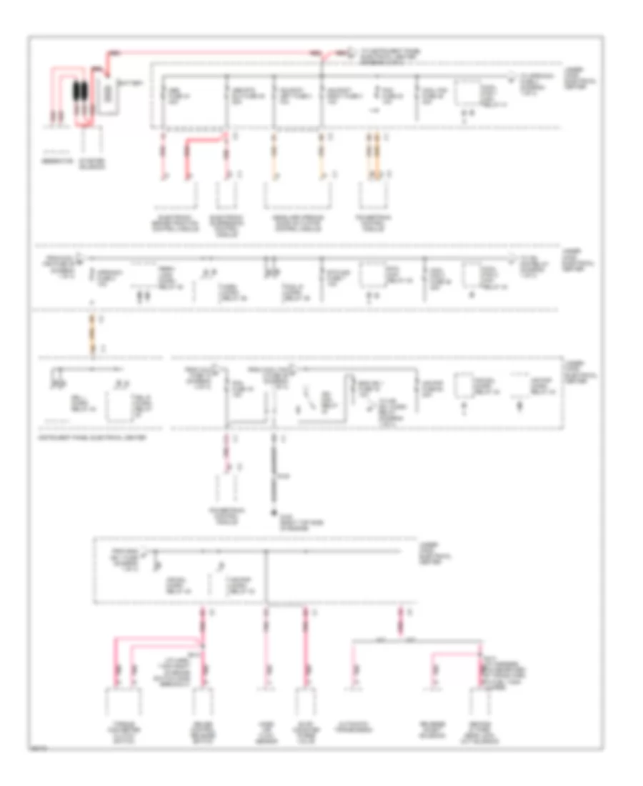
POWER DISTRIBUTION
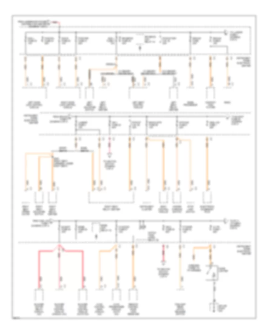
Power Distribution Wiring Diagram (1 of 4) for Chevrolet Corvette 1997
 https://portal-diagnostov.com/license.html
Automotive Electricians Portal FZCO
Automotive Electricians Portal FZCO
https://portal-diagnostov.com/license.html
https://portal-diagnostov.com/license.html
Automotive Electricians Portal FZCO
Automotive Electricians Portal FZCOList of elements for Power Distribution Wiring Diagram (1 of 4) for Chevrolet Corvette 1997:
- (i/p harn, 7.5cm right of brake switch conn breakout)
- A/t
- Abs fuse 44 40a
- Abs rtd elc fuse 45 20a
- Air pmp fuse 50 20a
- Air pmp micro- relay 33
- Air sol micro- relay 40
- Aproach fuse 2 10a
- Automatic transmission
- Battery
- Cool fan 1 mini- relay 41
- Cool fan 2 fuse 46 30a
- Cool fan 2 mini- relay 43
- Cool fan fuse 49 30a
- Cruise control release switch
- Drl l micro- relay 40
- Drl r micro- relay
- Electronic brake/traction control module
- Electronic suspension control module
- Eng ign 1 fuse 19 10a
- Evap canister purge valve
- F11
- Fog lp micro- relay 39
- From cool b fan fuse 49 (diagram 1 of 4)
- From cool fan c 2 fuse 46 (diagram 1 of 4)
- From eng d ign 1 fuse (diagram 1 of 4)
- From inj2 n fuse 18 (diagram 4 of 4)
- G120 (right top side of engine)
- Generator
- Hdlpmot left fuse 3 10a
- Hdlpmot right fuse 3 10a
- Headlamp opening door actuator control module
- Horn micro- relay 36
- Ign mini- relay
- Instrument panel electrical center
- M/t
- Mass air flow sensor
- Pcm fuse 16 15a
- Pcm fuse 23 10a
- Perim lmps micro- relay 38
- Pnk
- Powertrain control module
- Red
- Reverse inhibit solenoid
- Rtd mini- relay 42
- Rtd mod fuse 7 10a
- S120
- S213
- S414 (i/p harness, 7cm rearward of trans harn to fuel tank jumper)
- Second & third gear lock- out solenoid
- Starter solenoid
- To air sol micro- relay (diagram 1 of 4)
- To aproach fuse 2 (diagram 1 of 4)
- To ign mini-relay (diagram 1 of 4)
- To instrument panel electrical center (diagram 2 of 4)
- Torque converter clutch switch
- Under- hood electrical center
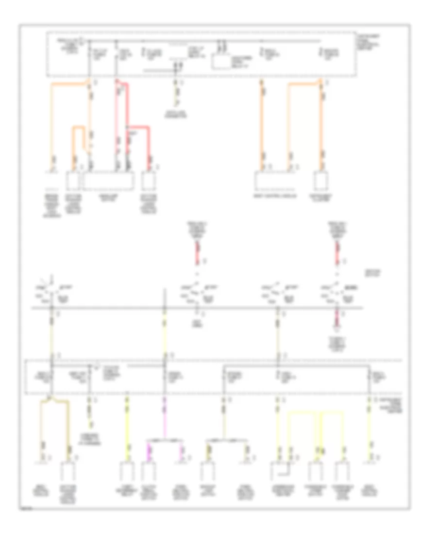
Power Distribution Wiring Diagram (2 of 4) for Chevrolet Corvette 1997
 https://portal-diagnostov.com/license.html
Automotive Electricians Portal FZCO
Automotive Electricians Portal FZCO
https://portal-diagnostov.com/license.html
https://portal-diagnostov.com/license.html
Automotive Electricians Portal FZCO
Automotive Electricians Portal FZCOList of elements for Power Distribution Wiring Diagram (2 of 4) for Chevrolet Corvette 1997:
- A12
- A14
- B11
- B12
- Base seats
- Bcm/clstr fuse 25 10a
- Blomot fuse 49 30a
- Blower motor control module (auto a/c)
- Blower motor control module (manual a/c)
- Blower motor relay (manual a/c)
- Body control module
- Bose fuse 28 20a
- Bose mini- relay 43
- Bose processor
- C/ltr fuse 7 25a
- C11
- C12
- Cigar lighter
- Cnsl cig fuse 1 25a
- Compact disc player
- Dcm l fuse 33 10a
- Dcm r fuse 30 10a
- Electronic accessory plug
- F/tnkdr fuse 32 15a
- F12
- Foglamp/ rear hatch release switch
- From cnsl cig g fuse 1 (diagram 2 of 4)
- From rdo/cd e fuse 5 (diagram 2 of 4)
- From underhood power distribution center (diagram 1 of 4)
- Hatch/ tonn micro- relay 39
- Hazard warning switch
- Hvac control head (manual a/c)
- Hvac programmer module (auto a/c)
- Hvaccon fuse 27 10a
- Ign 1 fuse 48 60a
- Ign 2 fuse 45 60a
- Instrument cluster
- Instrument panel electrical center
- Left door lock control module
- Left seat adjuster switch
- Left seat control module
- Left seat relay center
- Lumbar fuse 3 15a
- Pwr fdl fuse 34 25a
- Pwr fdr fuse 31 25a
- Pwr st c.b. 36 20a
- Pwr st/drv c.b. 35 20a
- Radio
- Rdo/cd fuse 20a
- Rdo/cd fuse 5 15a
- Red
- Remote control door lock receiver
- Right door lock control module
- Right seat adjuster switch
- Right seat relay center
- Right seat upper motor
- Rr defog fuse 46 40a
- Rr defog mini- relay 44
- S300 (right seat harness, under right seat)
- Scm l fuse 4 10a
- Splice pack
- Sport seats
- Stop lamp switch
- Stp/haz fuse 8 20a
- To blomot fuse 49 (diagram 2 of 4)
- To ignition switch (diagram 3 of 4)
- To lumbar fuse 3 (diagram 2 of 4)
- To pk t/ lp fuse 6 (diagram 3 of 4)
- W/ memory driver seat
- W/o memory
- W/o memory driver seat
- Wire end taped to i/p harness
Power Distribution Wiring Diagram (3 of 4) for Chevrolet Corvette 1997
 https://portal-diagnostov.com/license.html
Automotive Electricians Portal FZCO
Automotive Electricians Portal FZCO
https://portal-diagnostov.com/license.html
https://portal-diagnostov.com/license.html
Automotive Electricians Portal FZCO
Automotive Electricians Portal FZCOList of elements for Power Distribution Wiring Diagram (3 of 4) for Chevrolet Corvette 1997:
- (not used)
- 87a
- A/t
- A14
- Acc
- Asry off fuse 11 20a
- B11
- Backup lamp switch
- Bcm 2 fuse 23 10a
- Bcm a fuse 9 10a
- Bcm/ipc fuse 25 10a
- Bcmi 3 fuse 23 10a
- Body control module
- Brake/ trans- mission shift lock solenoid
- Btsi/bu fuse 21 10a
- Bulb test
- C/l aldl fuse 29 10a
- Clutch pedal position switch
- Crank fuse 14 10a
- Ctsy lp micro- relay 42
- D12
- Data link connector
- Daytime running lamps control module
- From c/ltr fuse 7 (diagram 2 of 4)
- From ign 1 fuse 48 (diagram 2 of 4)
- From ign 2 fuse 45 (diagram 2 of 4)
- Hdlp c.b. 52 20a
- Headlamp switch
- Ignition switch
- Instrument cluster
- Instrument panel electrical center
- M/t
- Monitored micro- relay 37
- Nca
- Off
- Park/ neutral position switch
- Pk t/lp fuse 6 10a
- Pnk
- Red
- Run
- S207
- Start
- Theft deterrent relay
- To bcmi 1 fuse 13 (diagram 4 of 4)
- To hvac fuse 18 (diagram 4 of 4)
- Underhood electrical center
- Windshield washer pump motor
- Windshield wiper switch
- Wsw fuse 10 25a
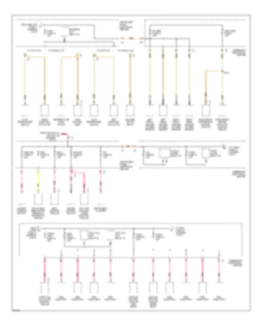
Power Distribution Wiring Diagram (4 of 4) for Chevrolet Corvette 1997
 https://portal-diagnostov.com/license.html
Automotive Electricians Portal FZCO
Automotive Electricians Portal FZCO
https://portal-diagnostov.com/license.html
https://portal-diagnostov.com/license.html
Automotive Electricians Portal FZCO
Automotive Electricians Portal FZCOList of elements for Power Distribution Wiring Diagram (4 of 4) for Chevrolet Corvette 1997:
- (diagram 3 of 4)
- A/c clu micro- relay 34
- A/c fuse 24 10a
- A11
- A13
- Abs trns fuse 5 10a
- B12
- Bcmi 1 fuse 13 10a
- Blower motor relay
- Body control module
- Cool fan 3 fuse 14 10a
- Cool fn 2 mini- relay 43
- Cool fn 3 mini- relay 43
- Cr cont fuse 20 10a
- Cruise control switch
- D13
- Daytime running lamps control module
- Electronic brake/ traction control module
- Electronic suspension control module
- F/ pmp fuse 13 10a
- F/pmp micro- relay 35
- From asry off fuse 11 (diagram 3 of 4)
- From f/ pmp fuse 13 (diagram 4 of 4)
- From ignition switch l
- Fuel injector 1
- Fuel injector 2
- Fuel injector 3
- Fuel injector 4
- Fuel injector 5
- Fuel injector 6
- Fuel injector 7
- Fuel injector 8
- Hazard warning switch
- Hvac control head
- Hvac fuse 18 10a
- Hvac programmer module
- Hzdt/sg fuse 15 20a
- Ignition control module (even bank)
- Ignition control module (odd bank)
- Inflatable restraints sensing & diagnostic module
- Injr 1 fuse 22 15a
- Injr 2 fuse 18 15a
- Instrument cluster
- Instrument panel electrical center
- Ipc fuse 25 10a
- Left electric actuator
- Left front heated oxygen sensor
- Left rear heated oxygen sensor
- Nca
- Oxygen fuse 15 15a
- Pnk
- Right electric actuator
- Right front heated oxygen sensor
- Right rear heated oxygen sensor
- Rr defog mini- relay 44
- S418
- Sdm fuse 16 15a
- Temperature door motor
- Throt- cont fuse 16 15a
- Throttle actuator control module
- To pcm fuse 16 (diagram 1 of 4)
- To throt fuse 16 (diagram 4 of 4)
- Underhood electrical center
- W/ auto a/c
- W/ manual a/c
POWER DOOR LOCKS
Power Door Lock Wiring Diagram for Chevrolet Corvette 1997
 https://portal-diagnostov.com/license.html
Automotive Electricians Portal FZCO
Automotive Electricians Portal FZCO
https://portal-diagnostov.com/license.html
https://portal-diagnostov.com/license.html
Automotive Electricians Portal FZCO
Automotive Electricians Portal FZCOList of elements for Power Door Lock Wiring Diagram for Chevrolet Corvette 1997:
- (i/p harness, 7 cm left of bcm connector c2 breakout) s208
- A12
- B11
- B12
- C10
- C11
- C12
- D12
- Data link connector (below left side of dash)
- Dcm/l fuse 33 10a
- Dcm/r fuse 30 10a
- F12
- G103 (right front wheelwell)
- G200 (left kick panel)
- G203 (right kick panel)
- Hot at all times
- Hvac con fuse 27 10a
- Instrument panel electrical center (behind left side of dash)
- Left door control module (inside left door)
- Left door lock cylinder switch
- Left door lock motor (inside left door)
- Left door switch
- Lock
- Pnk
- Pwr fdl fuse 34 25a
- Pwr fdr fuse 31 25a
- Remote control door lock receiver (behind left rear quarter panel trim)
- Right door control module (inside right door)
- Right door lock cylinder switch
- Right door lock motor (inside right door)
- Right door switch
- Splice pack 201
- Splice pack 202
- Splice pack 204 (i/p harness, serial data)
- Splice pack 206 (i/p harness, serial data)
- Splice pack 208 (behind right side of dash)
- Tan
- Unlock
POWER SEATS
6-Way Power Seat Wiring Diagram for Chevrolet Corvette 1997
 https://portal-diagnostov.com/license.html
Automotive Electricians Portal FZCO
Automotive Electricians Portal FZCO
https://portal-diagnostov.com/license.html
https://portal-diagnostov.com/license.html
Automotive Electricians Portal FZCO
Automotive Electricians Portal FZCOList of elements for 6-Way Power Seat Wiring Diagram for Chevrolet Corvette 1997:
- B c3
- B2 c3
- C c2
- C c3
- C2 a1
- C2 c
- C2 d
- C2 e
- C2 f
- C3 b
- C3 c
- C3 d
- C3 d2
- D c2
- D c3
- E c2
- F c2
- F8 c2
- Forward
- Forward/ reverse motor
- Front down
- Front up
- Front up/down motor
- G416 (left rear frame rail)
- Hot at all times
- Instrument panel electrical center
- Left front seat adjust switch (center of console)
- Left front seat lower motor assembly (under left front seat)
- Left front seat relay center (under left front seat)
- Lumbar minifuse 3 10a
- Pwr st/dvr circuit breaker 20a
- Pwr st/pass circuit breaker 20a
- Rear down
- Rear up
- Rear up/down motor
- Reverse
- Right front seat adjust switch (center of console)
- Right front seat lower motor assembly (under right front seat)
- Right front seat relay center (under right front seat)
- S303
- S416
- Scml minifuse 4 10a
- Splice pack
- Tan
Lumbar Wiring Diagram for Chevrolet Corvette 1997
 https://portal-diagnostov.com/license.html
Automotive Electricians Portal FZCO
Automotive Electricians Portal FZCO
https://portal-diagnostov.com/license.html
https://portal-diagnostov.com/license.html
Automotive Electricians Portal FZCO
Automotive Electricians Portal FZCOList of elements for Lumbar Wiring Diagram for Chevrolet Corvette 1997:
- (left rear frame rail) g416
- A c2
- B c1
- B c2
- B1 c2
- B2 c3
- C c1
- C c2
- C1 b
- C1 d
- C1 e
- C2 a
- C2 a1
- C2 b
- C2 c
- C2 d
- D c2
- Deflate
- Deflate relay
- E c1
- Hot at all times
- Inflate
- Inflate relay
- Instrument panel electrical center
- Left front seat adjust switch (center of console)
- Left front seat upper motor assembly (under left front seat)
- Lower lumbar
- Lower lumbar deflate
- Lower lumbar inflate
- Lumbar minifuse 3 15a
- Lumbar motor
- Pnk
- Pressure switch
- Right front seat adjust switch (center of console)
- Right front seat upper motor assembly (under right front seat)
- S300
- S303
- S416
- Scml minifuse 4 10a
- Side bolster
- Side bolster deflate
- Side bolster inflate
- Splice pack
- Upeer lumbar
- Upper lumbar deflate
- Upper lumbar inflate
POWER WINDOWS
Power Window Wiring Diagram for Chevrolet Corvette 1997
 https://portal-diagnostov.com/license.html
Automotive Electricians Portal FZCO
Automotive Electricians Portal FZCO
https://portal-diagnostov.com/license.html
https://portal-diagnostov.com/license.html
Automotive Electricians Portal FZCO
Automotive Electricians Portal FZCOList of elements for Power Window Wiring Diagram for Chevrolet Corvette 1997:
- B11
- B12
- Batt
- C11
- C12
- Data link connector (partial) (right of steering column)
- Dcm/l fuse 10a
- Dcm/r fuse 10a
- Down
- Driver window switch
- G200 (left kick panel)
- G203 (right kick panel)
- Gnd
- Hot at all times
- Instrument panel electrical center
- Left door control module (bottom center of left door)
- Left door switch
- Left window motor
- Lt win ctrl
- Lt win dn in
- Lt win up in
- Passenger window switch
- Pwr fdl fuse 25a
- Pwr fdr fuse 25a
- Right door control module (bottom center of right door)
- Right door switch
- Right window motor
- Rt win ctrl
- Rt win dn in
- Rt win up in
- S208 (i/p harn, approx 6cm left of the bcm conn c2 breakout)
- Serial data
- Splice pack
- Splice pack (i/p harn)
- Tan
RADIO
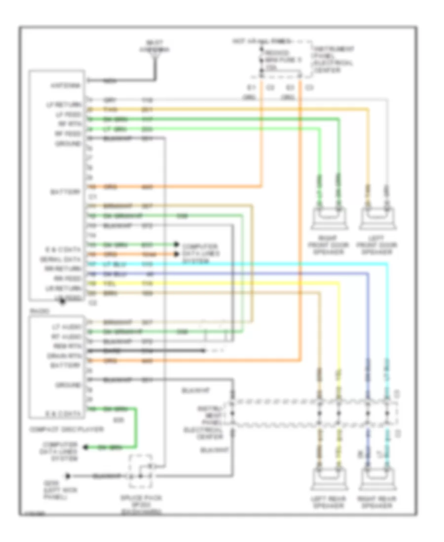
Radio Wiring Diagrams, with Bose System for Chevrolet Corvette 1997
 https://portal-diagnostov.com/license.html
Automotive Electricians Portal FZCO
Automotive Electricians Portal FZCO
https://portal-diagnostov.com/license.html
https://portal-diagnostov.com/license.html
Automotive Electricians Portal FZCO
Automotive Electricians Portal FZCOList of elements for Radio Wiring Diagrams, with Bose System for Chevrolet Corvette 1997:
- (right kick panel)
- A10
- A11
- A12
- Ant rly coil
- Antenna
- Antenna rly
- Ars 1
- B10
- B11
- B12
- Bare
- Battery
- Bose mini fuse 28 20a
- Bose mini relay
- Bose signal processor
- Compact disc player
- Computer data lines system
- Coupe
- D10
- Dr lk rly
- Drain
- Drain rtn
- E & c data
- E10
- E11
- E12
- F10
- F11
- Fc feed
- Fc return
- Fc rtn
- Fc spkr
- Front window antenna
- G200 (left kick panel)
- G203
- Ground
- Hardtop
- Hot at all times
- Instrument panel electrical center
- Left audio
- Left front door speaker
- Left rear speaker
- Lf audio
- Lf feed
- Lf low
- Lf return
- Lr feed
- Lr low
- Lr return
- Lt audio
- Mast antenna
- Nca
- Pnk
- Power antenna system
- Radio
- Radio antenna module (behind lower "b" pillar trim)
- Radio on
- Rdo/ant mini fuse 5 20a
- Rdo/cd mini fuse 5 15a
- Rear window antenna
- Rem rtn
- Remote rtn
- Rf draw
- Rf feed
- Rf low
- Rf rtn
- Rf sub
- Right front door speaker
- Right rear speaker
- Rr feed
- Rr low
- Rr return
- Rt audio
- S208
- S501
- S600
- Serial data
- Splice pack sp203 (i/p harn)
- Tan
- Woofer amplifier
Radio Wiring Diagrams, without Bose System for Chevrolet Corvette 1997
 https://portal-diagnostov.com/license.html
Automotive Electricians Portal FZCO
Automotive Electricians Portal FZCO
https://portal-diagnostov.com/license.html
https://portal-diagnostov.com/license.html
Automotive Electricians Portal FZCO
Automotive Electricians Portal FZCOList of elements for Radio Wiring Diagrams, without Bose System for Chevrolet Corvette 1997:
- A10
- Antenna
- B10
- Bare
- Battery
- Compact disc player
- Computer data lines system
- Drain rtn
- E & c data
- E11
- G200 (left kick panel)
- Ground
- Hot at all times
- Instru- ment panel electrical center
- Instrument panel electrical center
- Left front door speaker
- Left rear speaker
- Lf feed
- Lf return
- Lr feed
- Lr return
- Lt audio
- Mast antenna
- Nca
- Radio
- Rdo/cd mini fuse 5 15a
- Rem rtn
- Rf feed
- Rf rtn
- Right front door speaker
- Right rear speaker
- Rr feed
- Rr return
- Rt audio
- Serial data
- Splice pack sp203 (dash harn)
- Tan
- Tan d
SHIFT INTERLOCKS
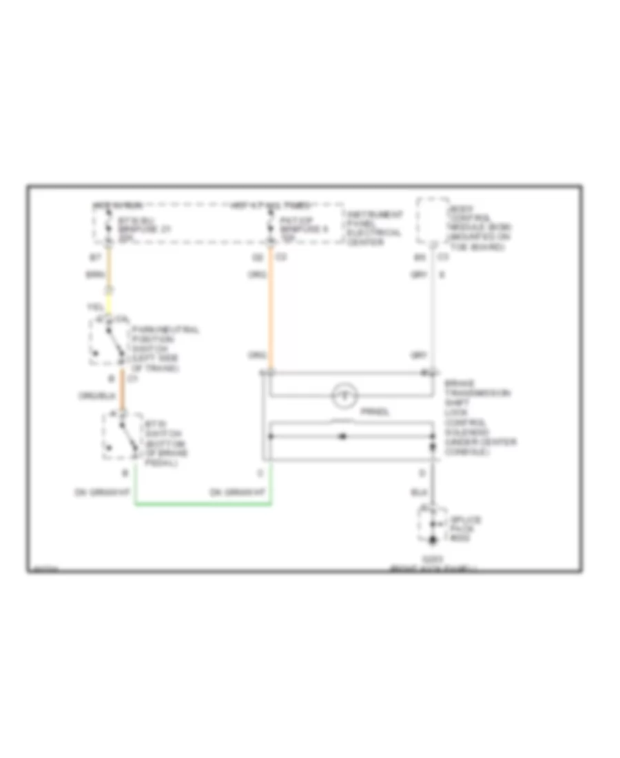
Shift Interlock Wiring Diagram for Chevrolet Corvette 1997
 https://portal-diagnostov.com/license.html
Automotive Electricians Portal FZCO
Automotive Electricians Portal FZCO
https://portal-diagnostov.com/license.html
https://portal-diagnostov.com/license.html
Automotive Electricians Portal FZCO
Automotive Electricians Portal FZCOList of elements for Shift Interlock Wiring Diagram for Chevrolet Corvette 1997:
- Body control module (bcm) (mounted on toe board)
- Brake transmission shift lock control solenoid (under center console)
- Btsi bu minifuse 21 20a
- Btsi switch (bottom of brake pedal)
- G203 (right kick panel)
- Hot at all times
- Hot in run
- Instrument panel electrical center
- Park/neutral position switch (left side of trans)
- Pkt/cp minifuse 6 10a
- Prndl
- Splice pack #202
STARTING/CHARGING
Charging Wiring Diagram for Chevrolet Corvette 1997
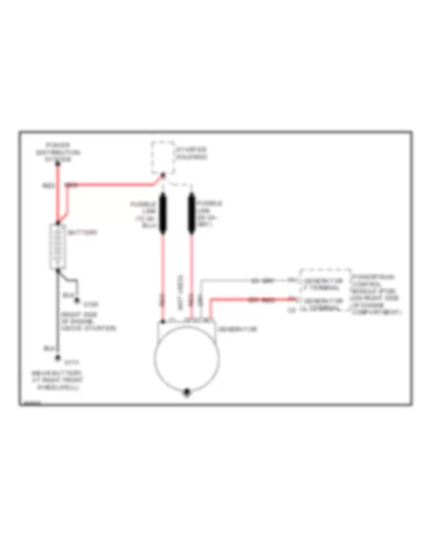 https://portal-diagnostov.com/license.html
Automotive Electricians Portal FZCO
Automotive Electricians Portal FZCO
https://portal-diagnostov.com/license.html
https://portal-diagnostov.com/license.html
Automotive Electricians Portal FZCO
Automotive Electricians Portal FZCOList of elements for Charging Wiring Diagram for Chevrolet Corvette 1997:
- (near battery, at right front wheelwell)
- (not used)
- (right side of engine, above starter)
- Battery
- G111
- G120
- Generator
- Generator f terminal
- Generator l terminal
- Power distribution system
- Powertrain control module (pcm) (on right side of engine compartment)
- Red
- Starter solenoid
Starting Wiring Diagram for Chevrolet Corvette 1997
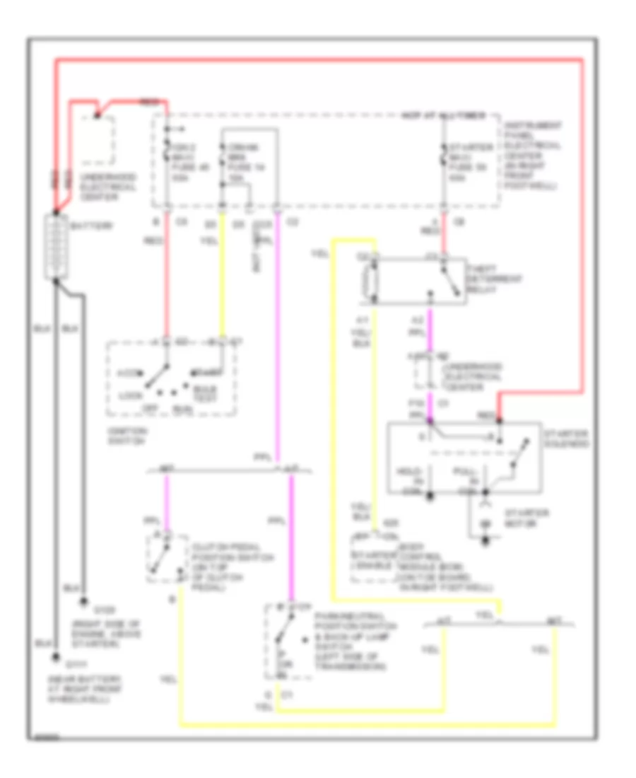 https://portal-diagnostov.com/license.html
Automotive Electricians Portal FZCO
Automotive Electricians Portal FZCO
https://portal-diagnostov.com/license.html
https://portal-diagnostov.com/license.html
Automotive Electricians Portal FZCO
Automotive Electricians Portal FZCOList of elements for Starting Wiring Diagram for Chevrolet Corvette 1997:
- (near battery, at right front wheelwell)
- (right side of engine, above starter)
- A red
- A/t
- A10
- Accy
- Battery
- Body control module (bcm) (on toe board, in right footwell)
- Bulb test
- Clutch pedal position switch (on top of clutch pedal)
- Crank mini fuse 14 10a
- D5 (not used)
- F10
- G c1
- G111
- G120
- Hold- in coil
- Hot at all times
- Ign 2 maxi fuse 45 60a
- Ignition switch
- Instrument panel electrical center (in right front footwell)
- Lock
- M/t
- Off
- P or n
- Park/neutral position switch & back-up lamp switch (left side of transmission)
- Pull- in coil
- Red
- Run
- Start
- Starter enable
- Starter maxi fuse 50 60a
- Starter motor
- Starter solenoid
- Theft deterrent relay
- Underhood electrical center
SUPPLEMENTAL RESTRAINTS
Supplemental Restraint Wiring Diagram for Chevrolet Corvette 1997
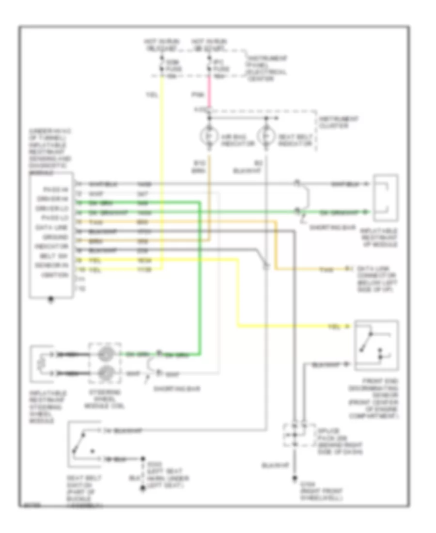 https://portal-diagnostov.com/license.html
Automotive Electricians Portal FZCO
Automotive Electricians Portal FZCO
https://portal-diagnostov.com/license.html
https://portal-diagnostov.com/license.html
Automotive Electricians Portal FZCO
Automotive Electricians Portal FZCOList of elements for Supplemental Restraint Wiring Diagram for Chevrolet Corvette 1997:
- (under hvac of tunnel) inflatable restraint sensing and diagnostic module
- A13
- Air bag indicator
- B12
- Belt sw
- Data line
- Data link connector (below left side of i/p)
- Driver hi
- Driver lo
- Front end discriminating sensor (front center of engine compartment)
- G104 (right front wheelwell)
- Ground
- Hot in run or start
- Ignition
- Indicator
- Inflatable restraint i/p module
- Inflatable restraint steering wheel module
- Instrument cluster
- Instrument panel electrical center
- Ipc fuse 10a
- Nca
- Nca b
- Pass hi
- Pass lo
- Pnk
- S303 (left seat harn, under left seat)
- Sdm fuse 15a
- Seat belt indicator
- Seat belt switch (part of buckle assembly)
- Sensor in
- Shorting bar
- Splice pack 208 (behind right side of dash)
- Steering wheel module coil
- Tan
TRANSMISSION
5.7L
5.7L (VIN G), Transmission Wiring Diagram, A/T for Chevrolet Corvette 1997
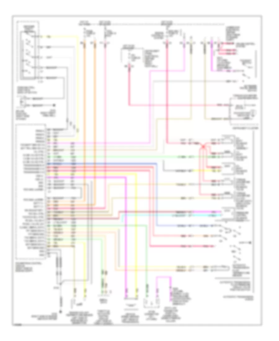 https://portal-diagnostov.com/license.html
Automotive Electricians Portal FZCO
Automotive Electricians Portal FZCO
https://portal-diagnostov.com/license.html
https://portal-diagnostov.com/license.html
Automotive Electricians Portal FZCO
Automotive Electricians Portal FZCOList of elements for 5.7L (VIN G), Transmission Wiring Diagram, A/T for Chevrolet Corvette 1997:
- 1-2 shift solenoid valve
- 1-2 ss valve ctrl
- 2-3 shift solenoid valve
- 2-3 ss valve ctrl
- 3-2 shift solenoid valve assembly
- 3-2 ss valve ctrl
- A13
- Automatic transmission (4l60-e)
- Automatic transmission fluid pressure manual valve position switch
- Automatic transmission fluid temperature sensor
- B16
- B6 pnk
- B7 pnk
- Batt (+)
- Class ii serial data
- Cruise control system
- Data link connector (partial) (under dash, under steering column)
- Decoder parity switch
- Ecm ign1 fuse 19 10a
- Ect sens gnd
- Ect sens sig in
- Engine controls system
- Engine coolant temperature sensor (left side of engine below generator)
- Ext trvl brk sw in
- Extended travel brake switch
- F11 pnk
- F2 pnk
- G103 (right front weelwell)
- G120 (right side of engine above starter)
- Gnd
- Hot at all times
- Hot in on or start
- Ign (run/start)
- Instrument cluster
- Instrument panel electrical center (right front footwell)
- Ipc fuse 25 10a
- Malfunction indicator lamp
- Mil ctrl
- Park/neutral position & back up switch
- Pc sol valve hi
- Pc sol valve low
- Pcm fuse 16 10a
- Pcm gnd jumper
- Pcmb fuse 23 10a
- Pnk
- Powertrain control module (right side of engine compt)
- Pressure control solenoid valve
- Prnd-a
- Prnd-b
- Prnd-c
- Prnd-p
- Red
- Rev
- S120
- S206 (i/p harn, approx 14 cm from blower motor control module conn breakout)
- S213 (i/p harn, 7.5 cm from brake sw conn break- out)
- Serial data
- Solid state
- Splice pack 208 (right side of dash)
- Star connector no 1 (i/p harn)
- Tac serial data
- Tan
- Tcc pwm sol ctrl
- Tcc sol ctrl
- Tcc/shift brk sw in
- Tcc/shift switch
- Tft sens gnd
- Tft sens sig in
- Throttle actuator control module (left side of throttle body)
- Torque converter clutch pulse width modulation solenoid valve
- Torque converter clutch solenoid valve
- Torque converter clutch switch
- Trans range a in
- Trans range b in
- Trans range c in
- Underhood electrical center (right rear of engine compt)
- Vehicle speed sensor (left rear of transmission)
- Vss hi
- Vss lo
5.7L (VIN G), Transmission Wiring Diagram, M/T for Chevrolet Corvette 1997
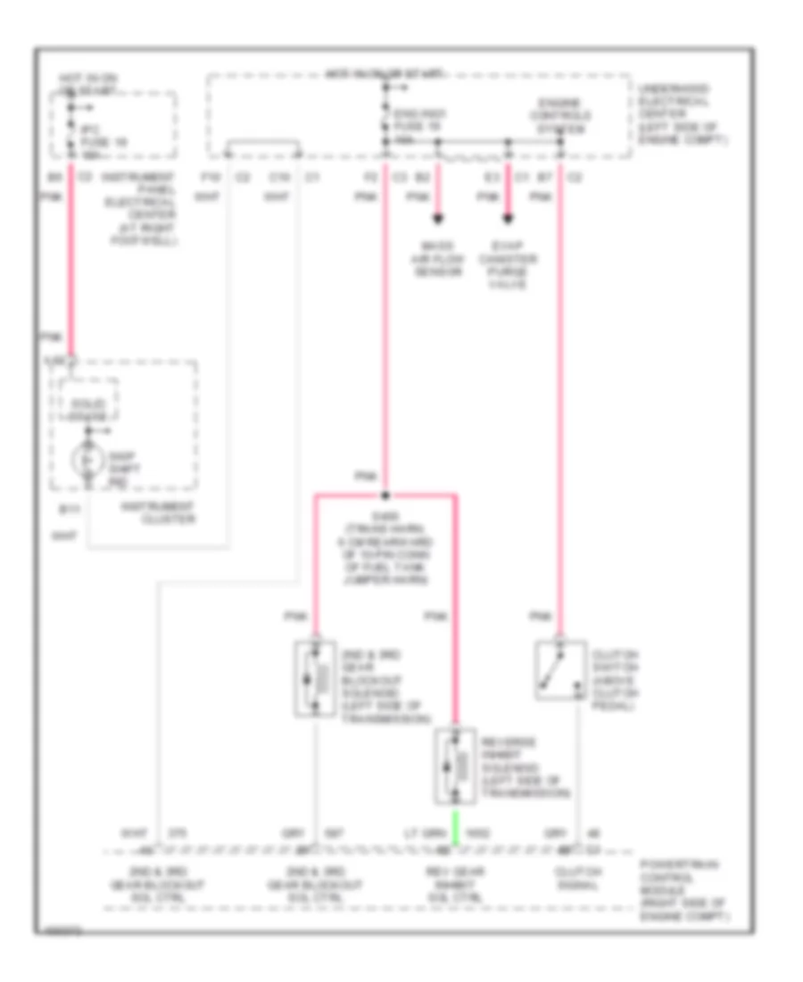 https://portal-diagnostov.com/license.html
Automotive Electricians Portal FZCO
Automotive Electricians Portal FZCO
https://portal-diagnostov.com/license.html
https://portal-diagnostov.com/license.html
Automotive Electricians Portal FZCO
Automotive Electricians Portal FZCOList of elements for 5.7L (VIN G), Transmission Wiring Diagram, M/T for Chevrolet Corvette 1997:
- 2nd & 3rd gear blockout sol ctrl
- 2nd & 3rd gear blockout solenoid (left side of transmission)
- A13
- B11
- C10
- Clutch signal
- Clutch switch (above clutch pedal)
- Eng ing1 fuse 19 10a
- Engine controls system
- Evap canister purge valve
- F10
- Hot in on or start
- Instrument cluster
- Instrument panel electrical center (at right footwell)
- Ipc fuse 19 10a
- Mass air flow sensor
- Pnk
- Powertrain control module (right side of engine compt)
- Rev gear inhibit sol ctrl
- Reverse inhibit solenoid (left side of transmission)
- S400 (trans harn, 6 cm rearward of 10-pin conn of fuel tank jumper harn)
- Skip shift ind
- Solid state
- Underhood electrical center (left side of engine compt)
TRUNK, TAILGATE, FUEL DOOR
Fuel Door Release Wiring Diagram for Chevrolet Corvette 1997
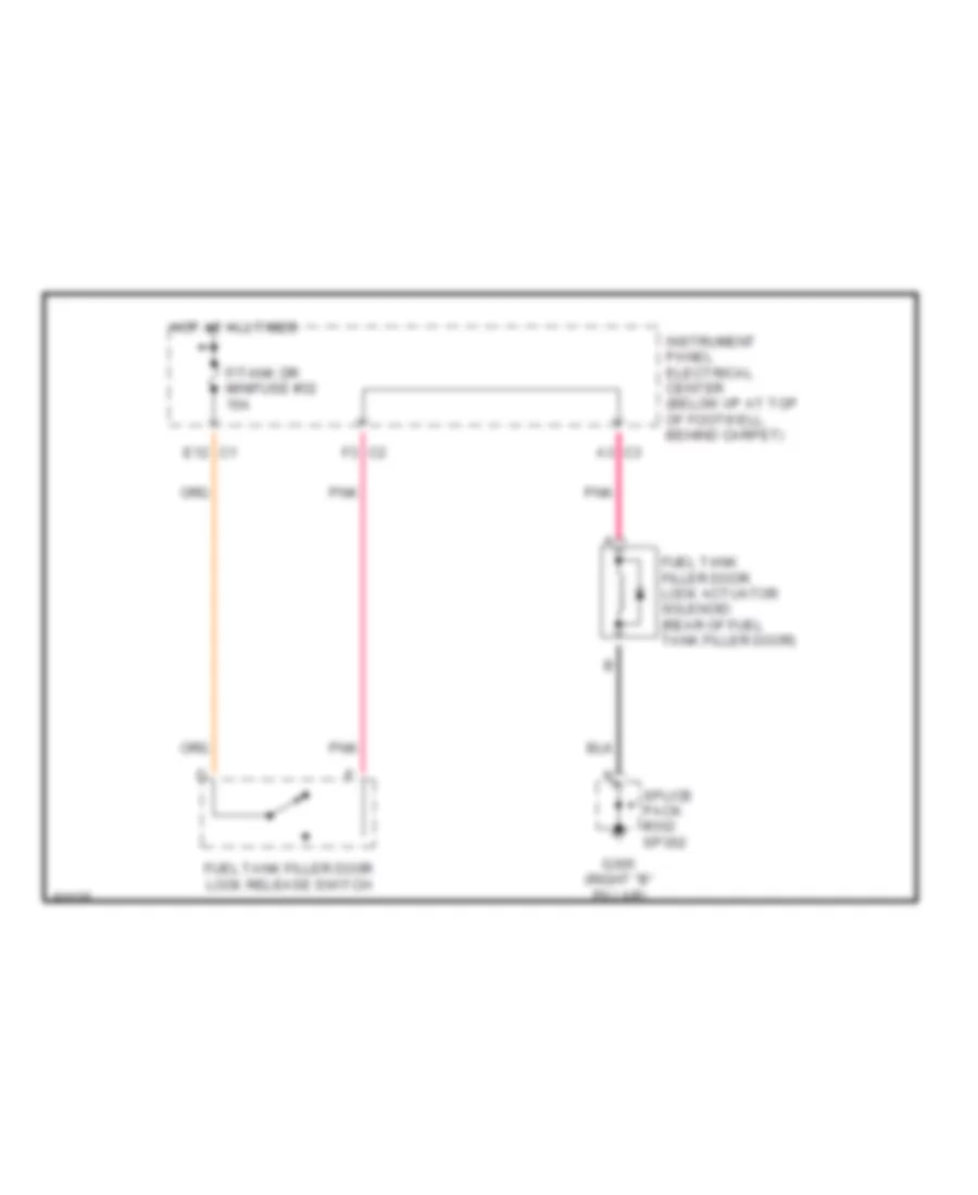 https://portal-diagnostov.com/license.html
Automotive Electricians Portal FZCO
Automotive Electricians Portal FZCO
https://portal-diagnostov.com/license.html
https://portal-diagnostov.com/license.html
Automotive Electricians Portal FZCO
Automotive Electricians Portal FZCOList of elements for Fuel Door Release Wiring Diagram for Chevrolet Corvette 1997:
- A3 c3
- E12 c1
- F/tank dr minifuse #32 15a
- F3 c2
- Fuel tank filler door lock actuator solenoid (rear of fuel tank filler door)
- Fuel tank filler door lock release switch
- G305 (right "b" pillar)
- Hot at all times
- Instrument panel electrical center (below i/p at top of footwell, behind carpet)
- Pnk
- Splice pack #302 sp302
Hatch Release Wiring Diagram for Chevrolet Corvette 1997
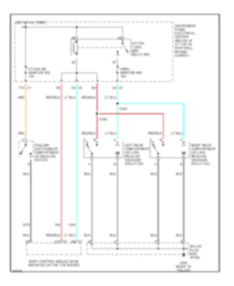 https://portal-diagnostov.com/license.html
Automotive Electricians Portal FZCO
Automotive Electricians Portal FZCO
https://portal-diagnostov.com/license.html
https://portal-diagnostov.com/license.html
Automotive Electricians Portal FZCO
Automotive Electricians Portal FZCOList of elements for Hatch Release Wiring Diagram for Chevrolet Corvette 1997:
- A9 c3
- Body control module (bcm) (mounted on the toe board)
- C1 b9
- C2 c12
- C8 c2
- F/tank dr minifuse #32 15a
- F12 c1
- Foglamp switch/rear compartment lid release switch
- G305 (right "b" pillar)
- H/rel minifuse #26 10a
- Hatch/ tonn mini relay #39
- Hot at all times
- Instrument panel electrical center (below i/p at top of footwell, behind carpet)
- Left rear compartment lid lock release solenoid (on latch)
- Right rear compartment lid lock release solenoid (on latch)
- S302
- S308
- Splice pack #302 sp302
WARNING SYSTEMS
Warning System Wiring Diagrams for Chevrolet Corvette 1997
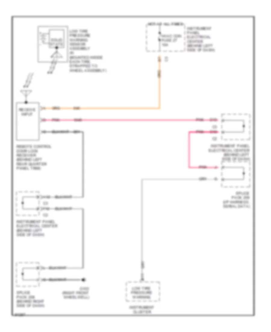 https://portal-diagnostov.com/license.html
Automotive Electricians Portal FZCO
Automotive Electricians Portal FZCO
https://portal-diagnostov.com/license.html
https://portal-diagnostov.com/license.html
Automotive Electricians Portal FZCO
Automotive Electricians Portal FZCOList of elements for Warning System Wiring Diagrams for Chevrolet Corvette 1997:
- (mounted inside each tire, strapped to wheel assembly)
- A11
- A12
- C10
- D12
- F12
- G103 (right front wheelwell)
- Hot at all times
- Hvac con fuse 27 10a
- Instrument cluster
- Instrument panel electrical center (behind left side of dash)
- Low tire pressure warning
- Low tire pressure warning sensor assembly (4)
- Pnk
- Receive input
- Remote control door lock receiver (behind left rear quarter panel trim)
- Solid state
- Splice pack 206 (i/p harness, serial data)
- Splice pack 208 (behind right side of dash)
WIPER/WASHER
Wiper/Washer Wiring Diagram for Chevrolet Corvette 1997
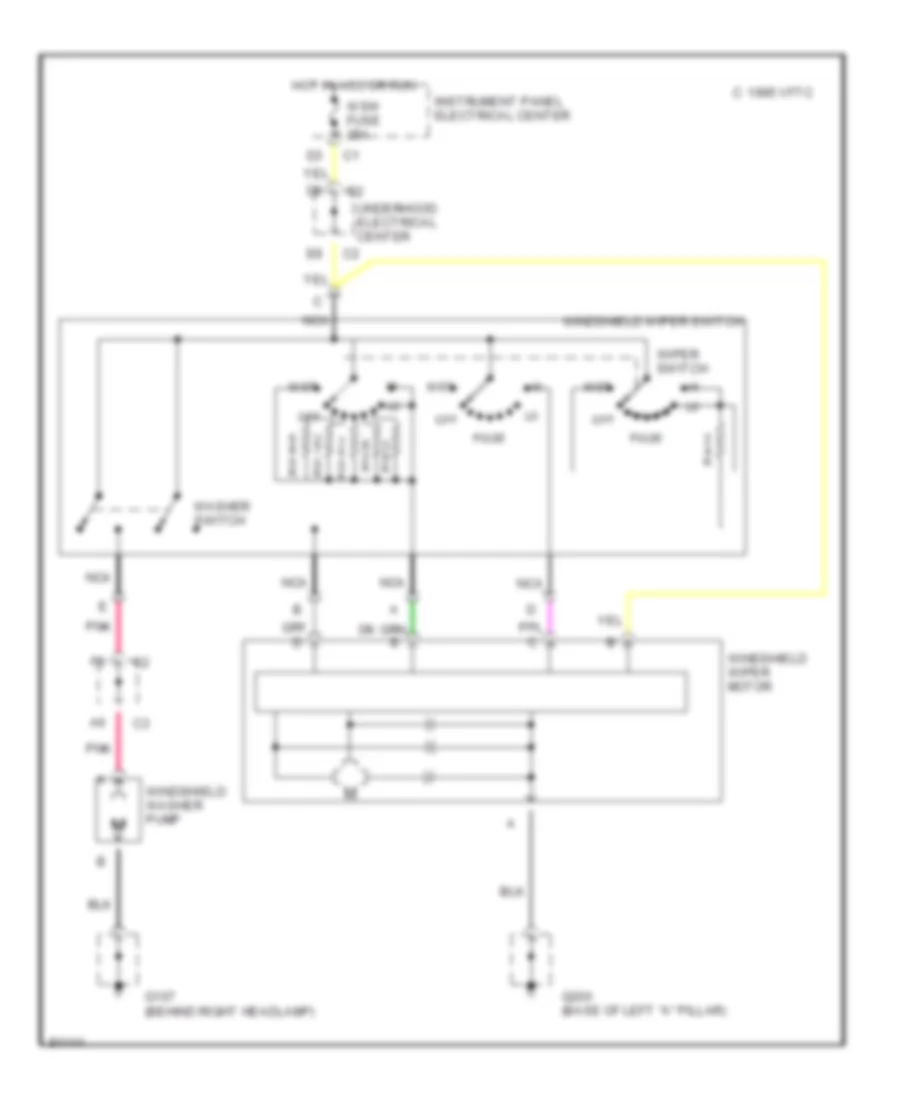 https://portal-diagnostov.com/license.html
Automotive Electricians Portal FZCO
Automotive Electricians Portal FZCO
https://portal-diagnostov.com/license.html
https://portal-diagnostov.com/license.html
Automotive Electricians Portal FZCO
Automotive Electricians Portal FZCOList of elements for Wiper/Washer Wiring Diagram for Chevrolet Corvette 1997:
- 1995 vftc c
- G107 (behind right headlamp)
- G200 (base of left "a" pillar)
- Hot in acc or run
- Instrument panel electrical center
- Mist
- Nca
- Off
- Pnk
- Pulse
- Underhood electrical center
- Washer switch
- Windshield washer pump
- Windshield wiper motor
- Windshield wiper switch
- Wiper switch
- Wsw fuse 25a

 Čeština
 Dansk
Dansk Deutsch
 Ελληνικά
 English
 English
 Español
 Suomi
Suomi Français
 Français
 עברית
עברית Hrvatski
 Magyar
 Italiano
 日本語
日本語 Nederlands
 Polski
 Português
 Português
 Română
 Русский
 Slovenčina
 Slovenščina
 Svenska
 Türkçe
 中文 (中国)
