AIR CONDITIONING
Compressor Wiring Diagram for Chevrolet Impala LS 2008
 https://portal-diagnostov.com/license.html
Automotive Electricians Portal FZCO
Automotive Electricians Portal FZCO
https://portal-diagnostov.com/license.html
https://portal-diagnostov.com/license.html
Automotive Electricians Portal FZCO
Automotive Electricians Portal FZCO
List of elements for Compressor Wiring Diagram for Chevrolet Impala LS 2008:
- (or 2751)
- 5 volt ref 1
- A/c cmprsr fuse 10a
- A/c cmprsr relay
- A/c comp strl
- A/c compressor clutch (part of a/c compressor, on lower left front of engine)
- A/c press sig
- A/c refrigerant pressure sensor (under air cleaner)
- A/c request ind
- A/c request switch
- Air bag/ display fuse 10a
- Battery
- Computer data lines system
- Data bus +
- Data bus -
- Emission 2 fuse 15a
- Engine control module (ecm) (inside air cleaner assembly)
- Except 5.3l 5.3l
- G113 (on front of automatic transaxle, left of g111)
- G202 (on right side of steering column below x201)
- Gnd
- Hot at all times
- Hot in run or start
- Hvac class 2
- Hvac control module (center of dash)
- Jx206 (on i/p harness, near steering column)
- Logic
- Low ref
- Pnk
- Tan
- Underhood fuse block (mounted to right strut tower)
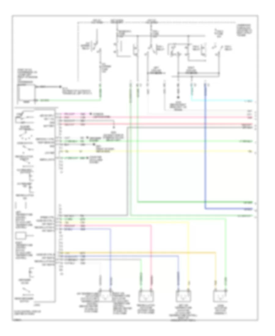
Manual A/C Wiring Diagram (1 of 2) for Chevrolet Impala LS 2008
 https://portal-diagnostov.com/license.html
Automotive Electricians Portal FZCO
Automotive Electricians Portal FZCO
https://portal-diagnostov.com/license.html
https://portal-diagnostov.com/license.html
Automotive Electricians Portal FZCO
Automotive Electricians Portal FZCOList of elements for Manual A/C Wiring Diagram (1 of 2) for Chevrolet Impala LS 2008:
- (part of a/c compressor, on lower left front of engine) a/c compressor clutch
- 87a
- A/c cmprsr fuse 10a
- A/c cmprsr relay
- A/c request ind
- A/c request switch
- Air temp a
- Air temp b
- Air temperature actuator (w/o auxiliary temperature control) (behind center of dash on hvac case)
- Battery
- Blower motor sw
- Computer data lines system
- Defog rly ctrl
- Defogger
- Defogger system
- Emission 2 fuse 15a
- Fan 1 fuse 30a
- Fan 1 relay
- Fan 2 fuse 30a
- Fan 2 relay
- Fan 3 relay
- G100 (behind right headlight, on frame)
- G113 (on front of automatic transaxle, left of g111)
- G201 (front of dash, above g202)
- G202 (on right side of steering column below x201)
- Gnd
- High
- Hot at all times
- Hot in run or start
- Hvac control module (center of dash)
- Ign 1 vol
- Ind
- Interior lights system
- Led dim sply
- Left air temperature actuator (w/ auxiliary temperature control) (right of accelerator pedal)
- Left cooling fan diode
- Left temperature control switch (w/ auxiliary temperature control)
- Logic
- Low
- Low ref
- Mode actuator (on hvac assembly)
- Mode dr ctrl a
- Mode dr ctrl b
- Mode switch
- Off
- On ind
- Pnk
- Rear defogger switch
- Recirculation
- Recirculation a
- Recirculation actuator (on right side of hvac case)
- Recirculation b
- Recirculation switch
- Right air temperature actuator (w/ auxiliary temperature control) (behind center of dash, on hvac case)
- Right cooling fan diode
- Right temperature control switch (w/ auxiliary temperature control)
- Serial data
- Speed ctrl
- Tan
- Temp sens sig
- Underhood fuse block (mounted to right strut tower)
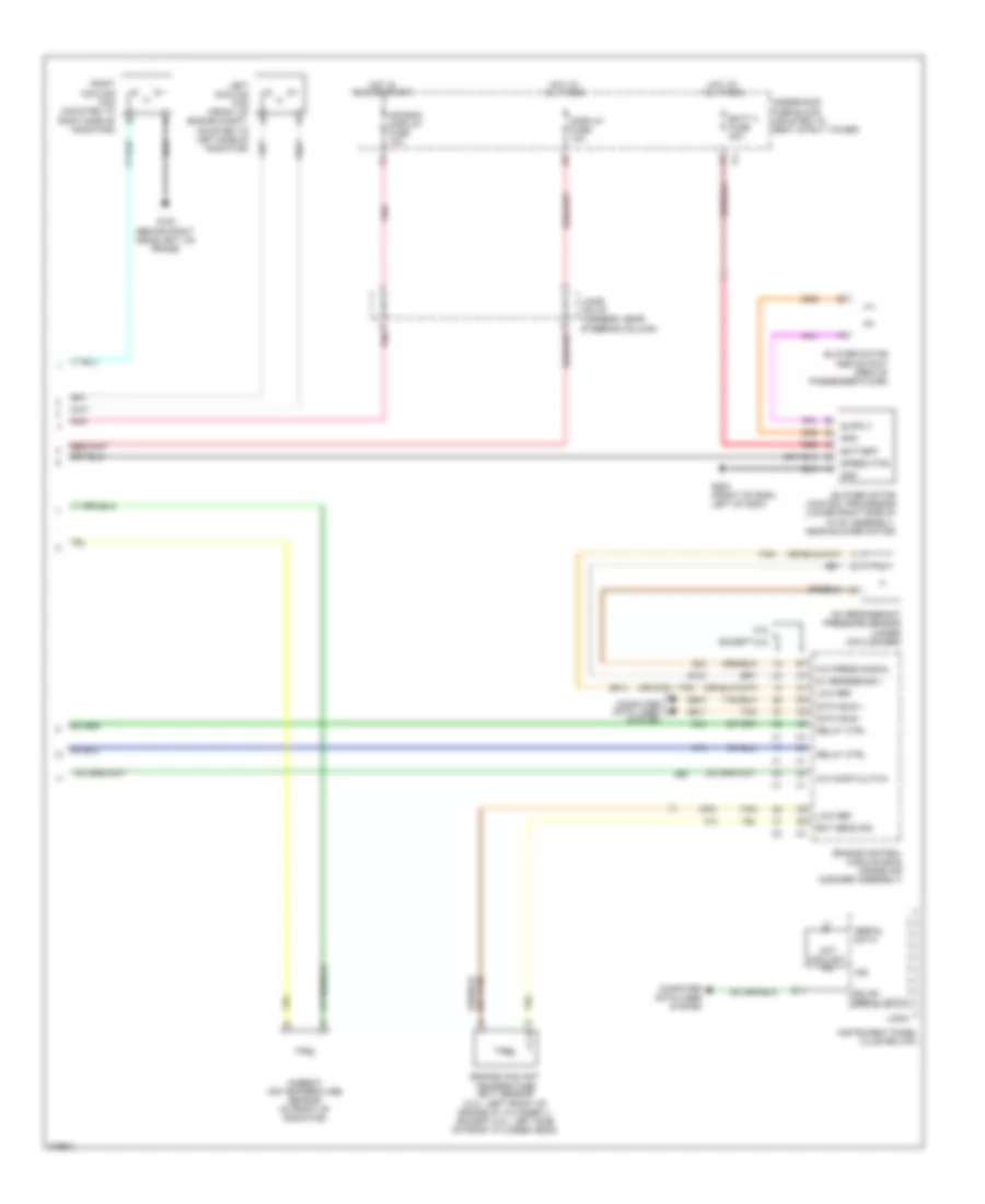
Manual A/C Wiring Diagram (2 of 2) for Chevrolet Impala LS 2008
 https://portal-diagnostov.com/license.html
Automotive Electricians Portal FZCO
Automotive Electricians Portal FZCO
https://portal-diagnostov.com/license.html
https://portal-diagnostov.com/license.html
Automotive Electricians Portal FZCO
Automotive Electricians Portal FZCOList of elements for Manual A/C Wiring Diagram (2 of 2) for Chevrolet Impala LS 2008:
- (behind right headlight, on frame)
- (or 2751)
- 5.3l
- 5v reference 1
- A/c comp clutch
- A/c press signal
- A/c refrigerant pressure sensor (under air cleaner)
- Air bag/ display fuse 10a
- Ambient air temperature sensor (in front of radiator)
- Batt 4 fuse 30a
- Battery
- Blower motor (above foot area of passenger floor)
- Blower motor control processor (lower right side of hvac assembly, near blower motor)
- Computer data lines system
- D pnk
- Data bus +
- Data bus -
- Display fuse 10a
- Ect sens sig
- Engine control module (ecm) (inside air cleaner assembly)
- Engine coolant temperature (ect) sensor (5.3l: left front of engine at cylinder 1) (except 5.3l: left side of front cylinder head)
- Except 5.3l
- G100
- G200 (front of dash, left of g204)
- Gmlan serial data
- Gnd
- Hot at all times
- Hot coolant ind
- Hot in run or start
- Ign
- Instrument panel cluster (ipc)
- Jx206 (on i/p harness, near steering column)
- Left cooling fan (front of engine compt, mounted to left side of radiator)
- Logic
- Low ref
- Pnk
- Red
- Relay ctrl
- Right cooling fan (mounted to right side of radiator)
- Serial data
- Speed ctrl
- Tan
- Underhood fuse block (mounted to right strut tower)
ANTI-LOCK BRAKES
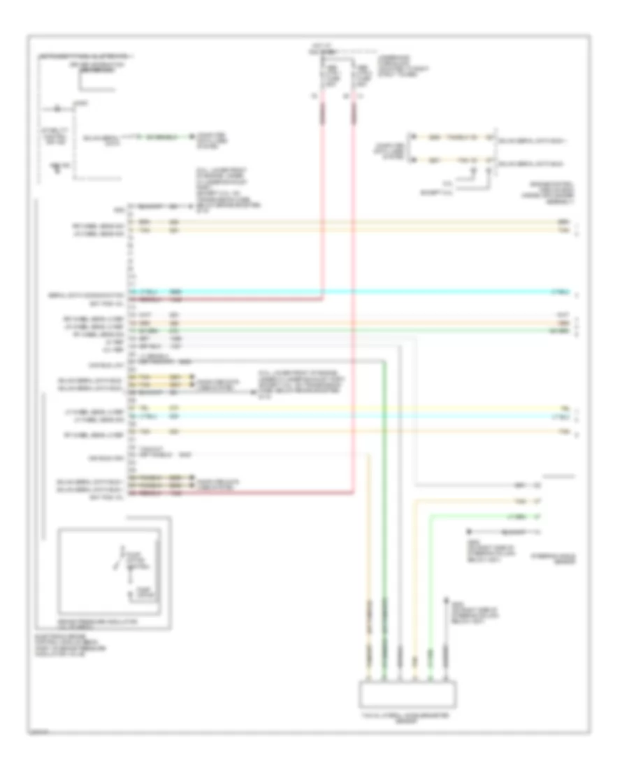
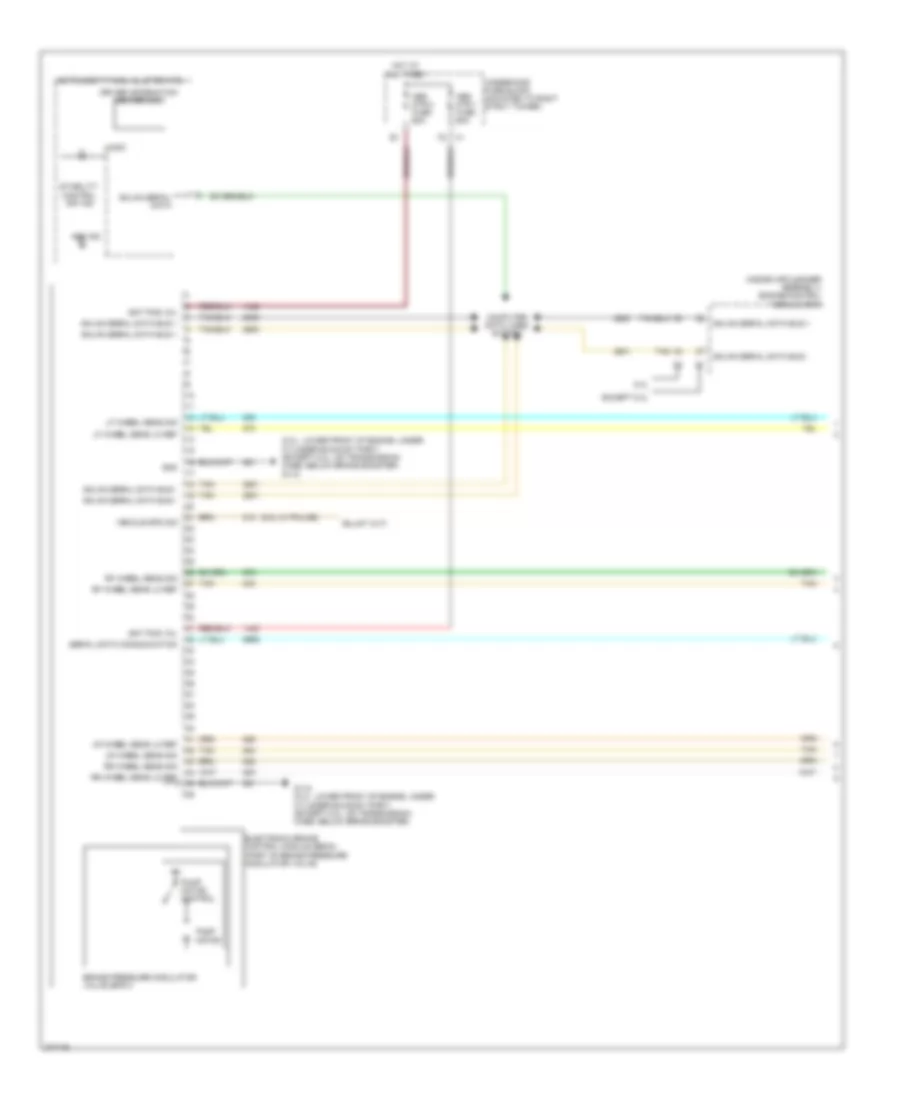
Anti-lock Brakes Wiring Diagram, with VSC (1 of 2) for Chevrolet Impala LS 2008
 https://portal-diagnostov.com/license.html
Automotive Electricians Portal FZCO
Automotive Electricians Portal FZCO
https://portal-diagnostov.com/license.html
https://portal-diagnostov.com/license.html
Automotive Electricians Portal FZCO
Automotive Electricians Portal FZCOList of elements for Anti-lock Brakes Wiring Diagram, with VSC (1 of 2) for Chevrolet Impala LS 2008:
- (5.3l: lower front of engine, under cylinder exhaust port) (except 5.3l: on transmission case, below brake booster) g115
- 12-v ref
- 5.3l
- 5v ref
- Abs ind
- Abs mtr 1 fuse 60a
- Abs mtr 2 fuse 60a
- Bat pos vol
- Brake pressure modulator valve (bpmv)
- Can bus high
- Can bus low
- Computer data lines system
- Driver information center (dic)
- Electronic brake control module (ebcm) (part of brake pressure modulator valve)
- Engine control module (ecm) (inside air cleaner assembly)
- Except 5.3l
- G202 (on right side of steering column below x201)
- Gmlan serial data
- Gmlan serial data bus +
- Gmlan serial data bus -
- Gnd
- Hot at all times
- Instrument panel cluster (ipc)
- Lf wheel sens lo ref
- Lf wheel sens sig
- Logic
- Lr wheel sens lo ref
- Lr wheel sens sig
- Pump motor
- Pump motor control
- Rf wheel sens lo ref
- Rf wheel sens sig
- Rr wheel sens lo ref
- Rr wheel sens sig
- Serial data communication
- Stability control off ind
- Steering angle sensor
- Tan
- Underhood fuse block (mounted to right strut tower)
- Yaw & lateral accelerometer sensor
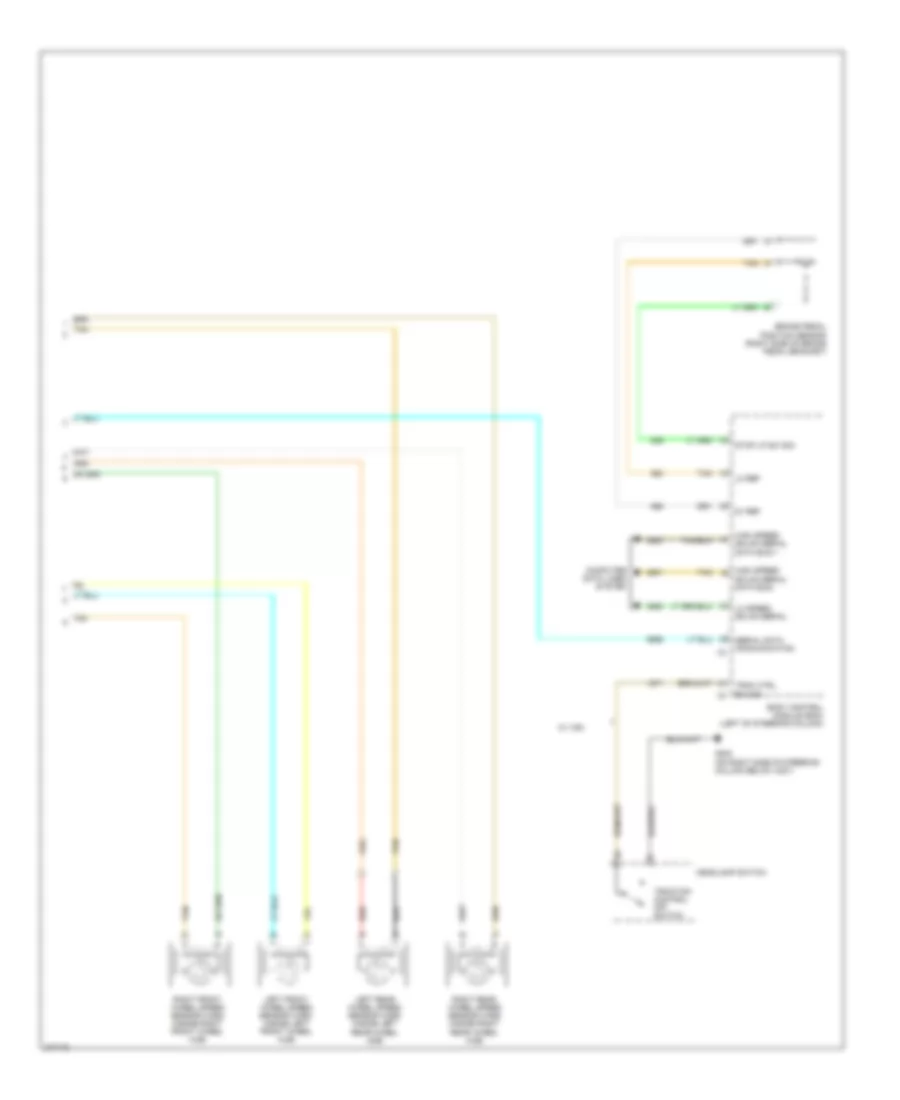
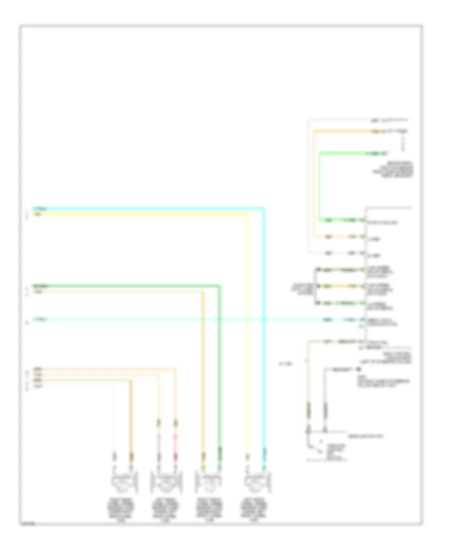
Anti-lock Brakes Wiring Diagram, with VSC (2 of 2) for Chevrolet Impala LS 2008
 https://portal-diagnostov.com/license.html
Automotive Electricians Portal FZCO
Automotive Electricians Portal FZCO
https://portal-diagnostov.com/license.html
https://portal-diagnostov.com/license.html
Automotive Electricians Portal FZCO
Automotive Electricians Portal FZCOList of elements for Anti-lock Brakes Wiring Diagram, with VSC (2 of 2) for Chevrolet Impala LS 2008:
- 5v ref
- Body control module (bcm) (left of steering column)
- Brake pedal position sensor (right side of brake pedal bracket)
- Computer data lines system
- G202 (on right side of steering column below x201)
- Headlamp switch
- High speed gmlan serial data bus +
- High speed gmlan serial data bus -
- Left front wheel speed sensor (wss) (inside left front wheel hub)
- Left rear wheel speed sensor (wss) (inside left rear wheel hub)
- Lo ref
- Lo speed gmlan serial
- Red
- Right front wheel speed sensor (wss) (inside right front wheel hub)
- Right rear wheel speed sensor (wss) (inside right rear wheel hub)
- Serial data communication
- Stop lp sw sig
- Tan
- Trac ctrl sw sig
- Traction control off switch
- W/ vsc
Anti-lock Brakes Wiring Diagram, without VSC (1 of 2) for Chevrolet Impala LS 2008
 https://portal-diagnostov.com/license.html
Automotive Electricians Portal FZCO
Automotive Electricians Portal FZCO
https://portal-diagnostov.com/license.html
https://portal-diagnostov.com/license.html
Automotive Electricians Portal FZCO
Automotive Electricians Portal FZCOList of elements for Anti-lock Brakes Wiring Diagram, without VSC (1 of 2) for Chevrolet Impala LS 2008:
- (5.3l w/ police)
- (5.3l: lower front of engine, under cylinder exhaust port) (except 5.3l: on transmission case, below brake booster) g115
- (inside air cleaner assembly) engine control module (ecm)
- 5.3l
- Abs ind
- Abs mtr 1 fuse 60a
- Abs mtr 2 fuse 60a
- Bat pos vol
- Brake pressure modulator valve (bpmv)
- Computer data lines system
- Driver information center (dic)
- Electronic brake control module (ebcm) (part of brake pressure modulator valve)
- Except 5.3l
- G115 (5.3l: lower front of engine, under cylinder exhaust port) (except 5.3l: on transmission case, below brake booster)
- Gmlan serial data
- Gmlan serial data bus +
- Gmlan serial data bus -
- Gnd
- Hot at all times
- Instrument panel cluster (ipc)
- Lf wheel sens lo ref
- Lf wheel sens sig
- Logic
- Lr wheel sens lo ref
- Lr wheel sens sig
- Pump motor
- Pump motor control
- Rf wheel sens lo ref
- Rf wheel sens sig
- Rr wheel sens lo ref
- Rr wheel sens sig
- Serial data communication
- Stability control off ind
- Tan
- Underhood fuse block (mounted to right strut tower)
- Vehicle spd sig
Anti-lock Brakes Wiring Diagram, without VSC (2 of 2) for Chevrolet Impala LS 2008
 https://portal-diagnostov.com/license.html
Automotive Electricians Portal FZCO
Automotive Electricians Portal FZCO
https://portal-diagnostov.com/license.html
https://portal-diagnostov.com/license.html
Automotive Electricians Portal FZCO
Automotive Electricians Portal FZCOList of elements for Anti-lock Brakes Wiring Diagram, without VSC (2 of 2) for Chevrolet Impala LS 2008:
- 5v ref
- Body control module (bcm) (left of steering column)
- Brake pedal position sensor (right side of brake pedal bracket)
- Computer data lines system
- G202 (on right side of steering column below x201)
- Headlamp switch
- High speed gmlan serial data bus +
- High speed gmlan serial data bus -
- Left front wheel speed sensor (wss) (inside left front wheel hub)
- Left rear wheel speed sensor (wss) (inside left rear wheel hub)
- Lo ref
- Lo speed gmlan serial
- Red
- Right front wheel speed sensor (wss) (inside right front wheel hub)
- Right rear wheel speed sensor (wss) (inside right rear wheel hub)
- Serial data communication
- Stop lp sw sig
- Tan
- Trac ctrl sw sig
- Traction control off switch
- W/ vsc
ANTI-THEFT
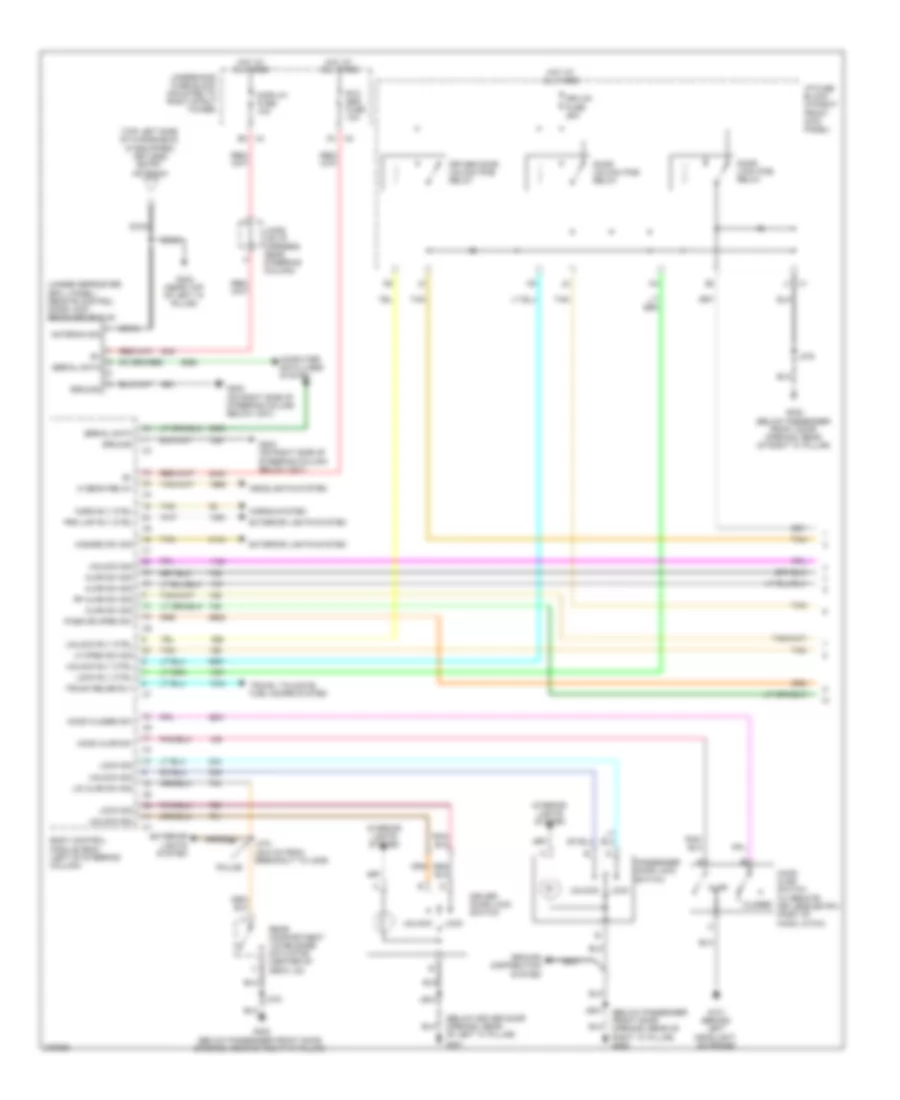
Forced Entry Wiring Diagram (1 of 2) for Chevrolet Impala LS 2008
 https://portal-diagnostov.com/license.html
Automotive Electricians Portal FZCO
Automotive Electricians Portal FZCO
https://portal-diagnostov.com/license.html
https://portal-diagnostov.com/license.html
Automotive Electricians Portal FZCO
Automotive Electricians Portal FZCOList of elements for Forced Entry Wiring Diagram (1 of 2) for Chevrolet Impala LS 2008:
- (below driver door opening, rear of left "a" pillar)
- (below passenger front door opening, rear of right "a" pillar) g302
- (top left side of windshield) (if equipped) keyless entry antenna
- (under defroster grill panel) remote control door lock receiver (rcdlr)
- Ajar
- Ajar sw sig
- Antenna sig
- B3 x4
- Body control module (bcm) (left of steering column)
- Closed
- Coax
- Computer data lines system
- Display fuse 10a
- Door lock pcb relay
- Door unlock pcb relay
- Dr/lck fuse 25a
- Driver door lock switch
- Driver door unlock pcb relay
- Exterior lights system
- G101 (behind left headlight, on frame)
- G202 (on right side of steering column below x201)
- G301
- G302 (below passenger front door opening, rear of right "a" pillar)
- G303 (near top of left "a" pillar)
- Ground
- Ground distribution system
- Hazard sw sig
- Headlights system
- Hi beam relay
- Hood ajar sw
- Hood ajar switch (w/ remote keyless entry) (part of hood latch)
- Hood closed sw
- Horn rly ctrl
- Horns system
- Hot at all times
- I/p fuse block (in right front kick panel)
- Interior lights system
- J1 x1
- J375
- J474 (45.5 cm from breakout to x409)
- J504
- J604
- Jx206 (on i/p harness, near steering column)
- Lf open sw sig
- Lid ajar sw sig
- Lock
- Lock rly ctrl
- Lock sig
- Pass dr open sw
- Passenger door lock switch
- Police
- Prk lmp rly ctrl
- Rear compartment lid release actuator (center of deck lid)
- Rf ajar sw sig
- Rvc sen fuse 10a
- Serial data
- Tan
- Trunk relse rly
- Trunk, tailgate, fuel doors system
- Underhood fuse block (mounted to right strut tower)
- Unlock
- Unlock rly ctrl
- Unlock sig
- X2 g1
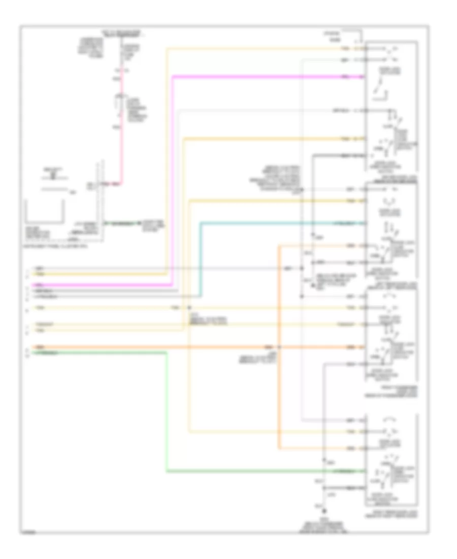
Forced Entry Wiring Diagram (2 of 2) for Chevrolet Impala LS 2008
 https://portal-diagnostov.com/license.html
Automotive Electricians Portal FZCO
Automotive Electricians Portal FZCO
https://portal-diagnostov.com/license.html
https://portal-diagnostov.com/license.html
Automotive Electricians Portal FZCO
Automotive Electricians Portal FZCOList of elements for Forced Entry Wiring Diagram (2 of 2) for Chevrolet Impala LS 2008:
- (below driver door opening, rear of left "a" pillar) g301
- (sedan: 5 cm from breakout to x313) (coupe: 5 cm from breakout to inflatable restraint sensing & diagnostic module) j315
- Air bag/ display fuse 10a
- Ajar
- Base
- Computer data lines system
- Door lock actuator
- Door lock ajar indicator switch
- Door lock open indicator switch
- Driver door lock (rear of driver door)
- Driver information center (dic)
- Front passenger door lock (rear of passenger door)
- G302 (below passenger front door opening, rear of right "a" pillar)
- Hot w/ ign main pcb relay energized
- Ign
- Ign 1 volt
- Instrument panel cluster (ipc)
- J303
- J314 (sedan: 16 cm from breakout to x313)
- J359 (sedan: 24 cm from breakout to x311)
- J375
- J505
- J604
- Jx206 (on i/p harness, near steering column)
- K4 x4
- Left rear door lock (rear of left rear door)
- Logic
- Low speed gmlan serial data
- Open
- Pnk
- Right rear door lock (rear of right rear door)
- Security ind
- Tan
- Underhood fuse block (mounted to right strut tower)
- Uplevel
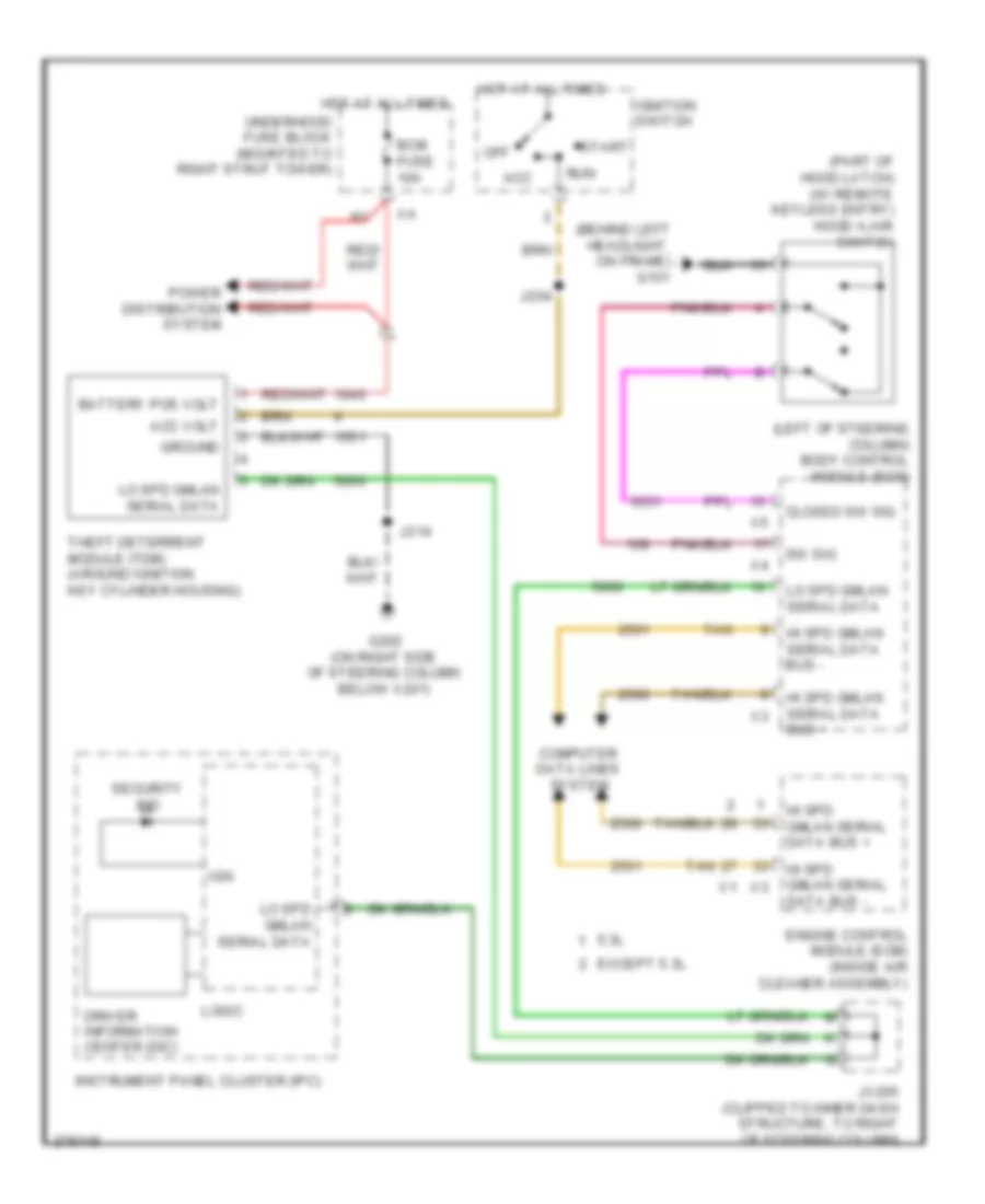
Pass-Key Wiring Diagram for Chevrolet Impala LS 2008
 https://portal-diagnostov.com/license.html
Automotive Electricians Portal FZCO
Automotive Electricians Portal FZCO
https://portal-diagnostov.com/license.html
https://portal-diagnostov.com/license.html
Automotive Electricians Portal FZCO
Automotive Electricians Portal FZCOList of elements for Pass-Key Wiring Diagram for Chevrolet Impala LS 2008:
- (behind left headlight, on frame) g101
- (left of steering column) body control module (bcm)
- (part of hood latch) (w/ remote keyless entry) hood ajar switch
- 5.3l
- Acc
- Acc volt
- Battery pos volt
- Bcm fuse 10a
- Closed sw sig
- Computer data lines system
- Driver information center (dic)
- Engine control module (ecm) (inside air cleaner assembly)
- Except 5.3l
- G202 (on right side of steering column below x201)
- Ground
- Hi spd gmlan serial data bus +
- Hi spd gmlan serial data bus -
- Hot at all times
- Ign
- Ignition switch
- Instrument panel cluster (ipc)
- J204
- J214
- Jx205 (clipped to inner dash structure, to right of steering column)
- Lo spd gmlan serial data
- Logic
- Off
- Power distribution system
- Run
- Security ind
- Start
- Sw sig
- Tan
- Theft deterrent module (tdm) (around ignition key cylinder housing)
- Underhood fuse block (mounted to right strut tower)
BODY CONTROL MODULES
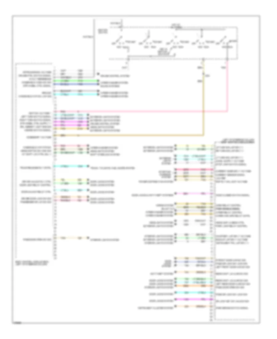
Body Control Modules Wiring Diagram (1 of 2) for Chevrolet Impala LS 2008
 https://portal-diagnostov.com/license.html
Automotive Electricians Portal FZCO
Automotive Electricians Portal FZCO
https://portal-diagnostov.com/license.html
https://portal-diagnostov.com/license.html
Automotive Electricians Portal FZCO
Automotive Electricians Portal FZCOList of elements for Body Control Modules Wiring Diagram (1 of 2) for Chevrolet Impala LS 2008:
- (left of steering column) body control module (bcm)
- 5-volt reference
- A/t shift lck ctrl sol v
- Acc
- Accessory voltage
- Anti-theft system
- Backup lmp sply voltage
- Body control module (bcm) (left of steering column)
- Courtesy lmp sply voltage
- Cruise control system
- Cruise ctrl switch signal
- Current sensor signal
- Current snsr sply voltage
- Door lock relay control
- Door locks & anti-theft systems
- Door locks system
- Door unlock relay ctrl
- Dr lock key sw unlock sig
- Driver door lock sw sig
- Drl ambient light sns sig
- Drv dr unlock rly ctrl
- Exterior lights system
- Ground
- Hazard switch signal
- Headlamp dim sw high sig
- Headlamp lo beam ctrl
- Headlights system
- Hood closed switch signal
- Horn relay control
- Horns system
- Hot at all times
- Ignition switch
- Ignition voltage 1
- Instrument cluster system
- Instrument pnl lmp sply v
- Interior lights system
- J204
- Key in ignition switch
- Left front door ajr sw sig
- Left rear door ajar sw sig
- Left turn switch signal
- Lf turn sig lmp sply v
- Low ref
- Lr turn sig lmp sply v
- Off
- Off/run/crank voltage
- Park brake switch signal
- Park enable signal park enable signal
- Park lamp relay control
- Pass door open sw sig
- Pass dr lock sw lock sig
- Passenger dr lck sw sig
- Pnk
- Power distribution system
- R front door ajr sw sig
- Rap rly coil sup voltage
- Rear comt lid ajar sw sig
- Right turn switch signal
- Rr turn sig lmp sply v
- Run
- Shift interlock system
- Sound systems
- Start
- Starting/ charging system
- Stop lamp switch signal
- Str wheel ctrl signal
- Tan
- Trunk release rly cntrl
- Trunk, tailgate, fuel doors system
- Windshield wash sw sig
- Windshield wip mtr sw
- Windshield wip sw low sig
- Wiper high spd relay cntrl
- Wiper relay control
- Wiper/washer system
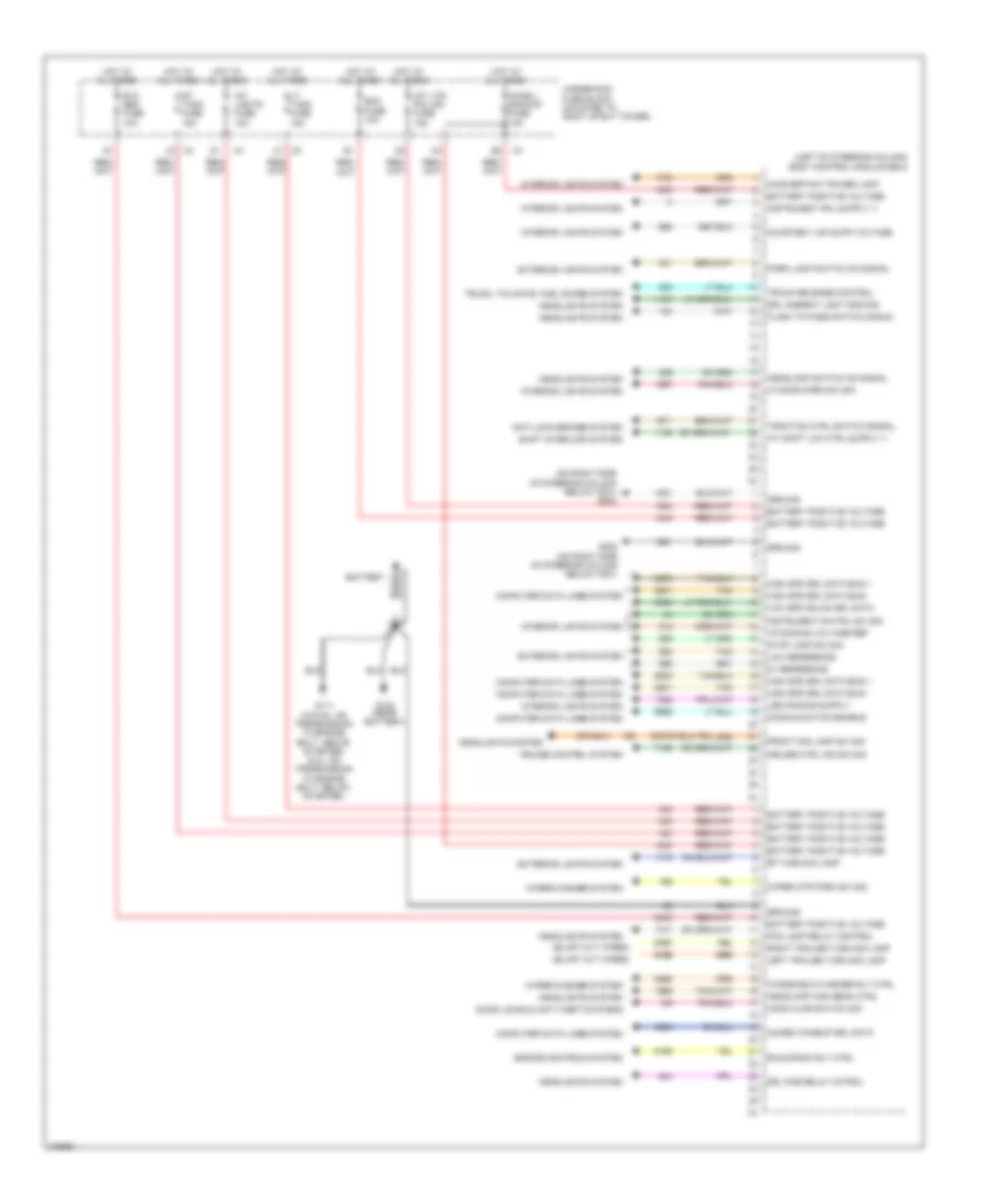
Body Control Modules Wiring Diagram (2 of 2) for Chevrolet Impala LS 2008
 https://portal-diagnostov.com/license.html
Automotive Electricians Portal FZCO
Automotive Electricians Portal FZCO
https://portal-diagnostov.com/license.html
https://portal-diagnostov.com/license.html
Automotive Electricians Portal FZCO
Automotive Electricians Portal FZCOList of elements for Body Control Modules Wiring Diagram (2 of 2) for Chevrolet Impala LS 2008:
- (left of steering column) body control module (bcm)
- (on right side of steering column below x201) g202
- (or 6841)
- 5v reference
- Acces wakeup srl data
- Anti-lock brakes system
- Battery
- Battery positive voltage
- Bcm fuse 10a
- Chmsl/ backup fuse 10a
- Communication enable
- Computer data lines system
- Courtesy lmp supp voltage
- Cruise control system
- Cruise ctrl ind dim sig
- Door locks & anti-theft systems
- Drl ambient light sns sig
- Drl pcb relay cotrol
- Engine controls system
- Exterior lights system
- Flash to pass switch signal
- Fog lamp relay control
- Front fog lamp sw sig
- G102 (near battery)
- G111 (3.5/3.9l: on transmission to engine bolt, above starter) (5.3l: on transmission to engine bolt, below starter)
- G202 (on right side of steering column below x201)
- Ground
- Headlamp high beam ctrl
- Headlamp switch on signal
- Headlights system
- High spd srl data bus +
- High spd srl data bus -
- Hood ajar switch sig
- Hot at all times
- I/p dimming voltage ref
- Inadvertant power lamp
- Instrument dim pnl sw sig
- Int lights fuse 10a
- Int lts/ pnl dim fuse 15a
- Interior lights system
- Left trailer turn sig lamp
- Lf door open sw sig
- Low reference
- Low spd gmlan srl data
- Lt t/sig fuse 15a
- Park lamp switch on signal
- Rf turn sig lamp
- Right trailer turn sig lamp
- Rt t/sig fuse 15a
- Run/crank rly ctrl
- Rvc sen fuse 10a
- Shift interlock system
- Stop lamp sw sig
- Tan
- Traction ctrl switch signal
- Trunk release control
- Trunk, tailgate, fuel doors system
- Underhood fuse block (mounted to right strut tower)
- Windshield washer rly ctrl
- Wiper mtr park sw sig
- Wiper/washer system
COMPUTER DATA LINES
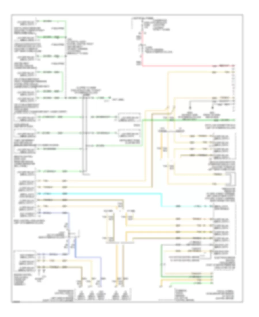
Computer Data Lines Wiring Diagram for Chevrolet Impala LS 2008
 https://portal-diagnostov.com/license.html
Automotive Electricians Portal FZCO
Automotive Electricians Portal FZCO
https://portal-diagnostov.com/license.html
https://portal-diagnostov.com/license.html
Automotive Electricians Portal FZCO
Automotive Electricians Portal FZCOList of elements for Computer Data Lines Wiring Diagram for Chevrolet Impala LS 2008:
- (clipped to inner dash structure, to right of steering column) jx205
- (not used)
- 5.3l
- Acc wakeup serial data
- Body control module (bcm) (left of steering column)
- Can bus high serial data
- Can bus low serial data
- Data link connector (dlc) (left of steering column)
- Digital radio receiver (mounted to rear of right rear wheelwell)
- Display fuse 10a
- Electronic brake control module (ebcm) (part of brake pressure modulator valve)
- Engine control module (ecm) (inside air cleaner assembly)
- Except 5.3l
- G201 (front of dash, above g202)
- G202 (on right side of steering column below x201)
- Heated seat control module (under driver seat)
- Hi spd gmlan serial data +
- Hi spd gmlan serial data -
- Hi spd serial data +
- Hi spd serial data -
- Hot at all times
- Hvac module (center of dash)
- If equipped
- Inflatable restraint front passenger presense system (pps) module (under front passenger seat)
- Inflatable restraint sensing & diagnostic module (sdm) (under front passenger seat, under carpet)
- Instrument panel cluster (ipc)
- J350 (w/ digital audio system, onstar, front heater seat) (on body harness, 14.5 cm from breakout to g302)
- Jx206 (on i/p harness, near steering column)
- Jx207 (on i/p harness, near steering column)
- Low spd gmlan
- Low spd gmlan serial data
- Radio
- Remote control door lock receiver (rcdlr) (under defroster grill panel)
- Serial data
- Serial data comm enable
- Steering angle sensor (w/ active control brake)
- Tan
- Terminator resistor (w/ gps: in body harness, left side of rear compt) (w/o gps: in body harness, near connector x203)
- Theft deterrent exciter module (around ignition key cylinder housing)
- Transmission control module (tcm) (left side of engine compt in with air cleaner)
- Underhood fuse block (mounted to right strut tower)
- Vehicle communication interface module (vcim) (mounted to rear of left rear wheelhouse)
- W/ abs
- W/ active control brake
- W/ onstar
- W/o abs
- W/o active control brake
- W/o onstar
- X111
- X4 b3
- Yaw & lateral accelerometer sensor (w/ active control brake)
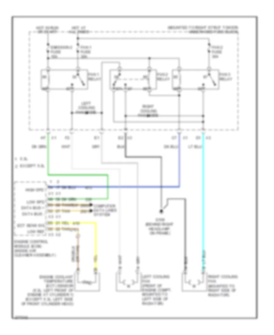
COOLING FAN
Cooling Fan Wiring Diagram for Chevrolet Impala LS 2008
 https://portal-diagnostov.com/license.html
Automotive Electricians Portal FZCO
Automotive Electricians Portal FZCO
https://portal-diagnostov.com/license.html
https://portal-diagnostov.com/license.html
Automotive Electricians Portal FZCO
Automotive Electricians Portal FZCOList of elements for Cooling Fan Wiring Diagram for Chevrolet Impala LS 2008:
- (mounted to right strut tower) underhood fuse block
- 5.3l
- 87a
- Computer data lines system
- Data bus +
- Data bus -
- Ect sens sig
- Emission 2 fuse 15a
- Engine control module (ecm) (inside air cleaner assembly)
- Engine coolant temperature (ect) sensor (5.3l: left front of engine at cylinder 1) (except 5.3l: left side of front cylinder head)
- Except 5.3l
- Fan 1 fuse 30a
- Fan 1 relay
- Fan 2 fuse 30a
- Fan 2 relay
- Fan 3 relay
- G100 (behind right headlamp, on frame)
- High spd
- Hot at all times
- Hot in run or start
- Left cooling fan (front of engine compt, mounted to left side of radiator)
- Left cooling fan diode
- Low ref
- Low spd
- Right cooling fan (mounted to right side of radiator)
- Right cooling fan diode
- Tan
CRUISE CONTROL
Cruise Control Wiring Diagram (1 of 2) for Chevrolet Impala LS 2008
 https://portal-diagnostov.com/license.html
Automotive Electricians Portal FZCO
Automotive Electricians Portal FZCO
https://portal-diagnostov.com/license.html
https://portal-diagnostov.com/license.html
Automotive Electricians Portal FZCO
Automotive Electricians Portal FZCOList of elements for Cruise Control Wiring Diagram (1 of 2) for Chevrolet Impala LS 2008:
- (except 5.3l: on transmission to engine bolt, above starter) (5.3l: on transmission to engine bolt, below starter) g111
- 5 volt ref
- 5 volt ref 1
- 5 volt ref 2
- 5.3l
- Body control module (bcm) (left of steering column)
- Brake pedal position sensor (right side of brake pedal bracket)
- Computer data lines system
- Cruise ctrl ind sig
- Cruise ctrl sw sig
- Cruise ind
- Ecm ign fuse 10a
- Engine control module (ecm) (inside air cleaner assembly)
- Except 5.3l
- Gnd
- Hot w/ ign main pcb relay energized
- Ign
- Ign 1 voltage
- Inflatable restraint steering wheel module coil (in steering column behind steering wheel)
- Instrument panel cluster (ipc)
- J105 (except 5.3l: in engine wiring harness, 5 cm from x100 breakout towards starter) (5.3l: in engine wiring harness, 5.5 cm from breakout to starter)
- Logic
- Low ref
- Nca
- Pnk
- Sens 1 sig
- Sens 2 sig
- Serial data
- Serial data +
- Serial data -
- Sply voltage
- Steering ctrl sig
- Stop lamp sw sig
- Tac motor ctrl 1
- Tac motor ctrl 2
- Tan
- Tp sensor 1 sig
- Tp sensor 2 sig
- Underhood fuse block (mounted to right strut tower)
- Vehicle speed sig
- X275
- X277
Cruise Control Wiring Diagram (2 of 2) for Chevrolet Impala LS 2008
 https://portal-diagnostov.com/license.html
Automotive Electricians Portal FZCO
Automotive Electricians Portal FZCO
https://portal-diagnostov.com/license.html
https://portal-diagnostov.com/license.html
Automotive Electricians Portal FZCO
Automotive Electricians Portal FZCOList of elements for Cruise Control Wiring Diagram (2 of 2) for Chevrolet Impala LS 2008:
- (top of engine) throttle body
- 5.3l
- Accelerator pedal position (app) sensor (3.5l) (above accelerator pedal)
- Accelerator pedal position (app) sensor (3.9l) (above accelerator pedal)
- Accelerator pedal position (app) sensor (5.3l) (above accelerator pedal)
- Cruise on ind
- Except 5.3l
- Front sig high
- Front sig low
- J213 (on steering wheel harness, behind inflatable restraint steering wheel module)
- Left steering wheel control switch
- On/off canecel
- Res+
- Right steering wheel control switch
- Set-
- Stop lamp sw sig
- Tan
- Transmission control module (tcm) (left side of engine compt in with air cleaner)
- Vehicle speed sensor (vss) (right side of transaxle, near right axle shaft)
- Vehicle speed sig
- W/ steering wheel
- W/o steering wheel
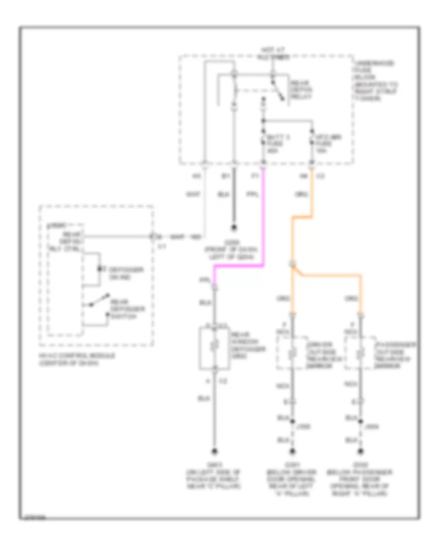
DEFOGGERS
Defoggers Wiring Diagram for Chevrolet Impala LS 2008
 https://portal-diagnostov.com/license.html
Automotive Electricians Portal FZCO
Automotive Electricians Portal FZCO
https://portal-diagnostov.com/license.html
https://portal-diagnostov.com/license.html
Automotive Electricians Portal FZCO
Automotive Electricians Portal FZCOList of elements for Defoggers Wiring Diagram for Chevrolet Impala LS 2008:
- Batt 3 fuse 40a
- Defogger on ind
- Driver outside rearview mirror
- F nca
- G200 (front of dash, left of g204)
- G301 (below driver door opening, rear of left "a" pillar)
- G302 (below passenger front door opening, rear of right "a" pillar)
- G403 (on left side of package shelf, near "c" pillar)
- Hot at all times
- Htd mir fuse 10a
- Hvac control module (center of dash)
- J505
- J604
- Logic
- Nca
- Passenger outside rearview mirror
- Rear defog relay
- Rear defog rly ctrl
- Rear defogger switch
- Rear window defogger grid
- Underhood fuse block (mounted to right strut tower)
ENGINE PERFORMANCE
3.5L VIN K
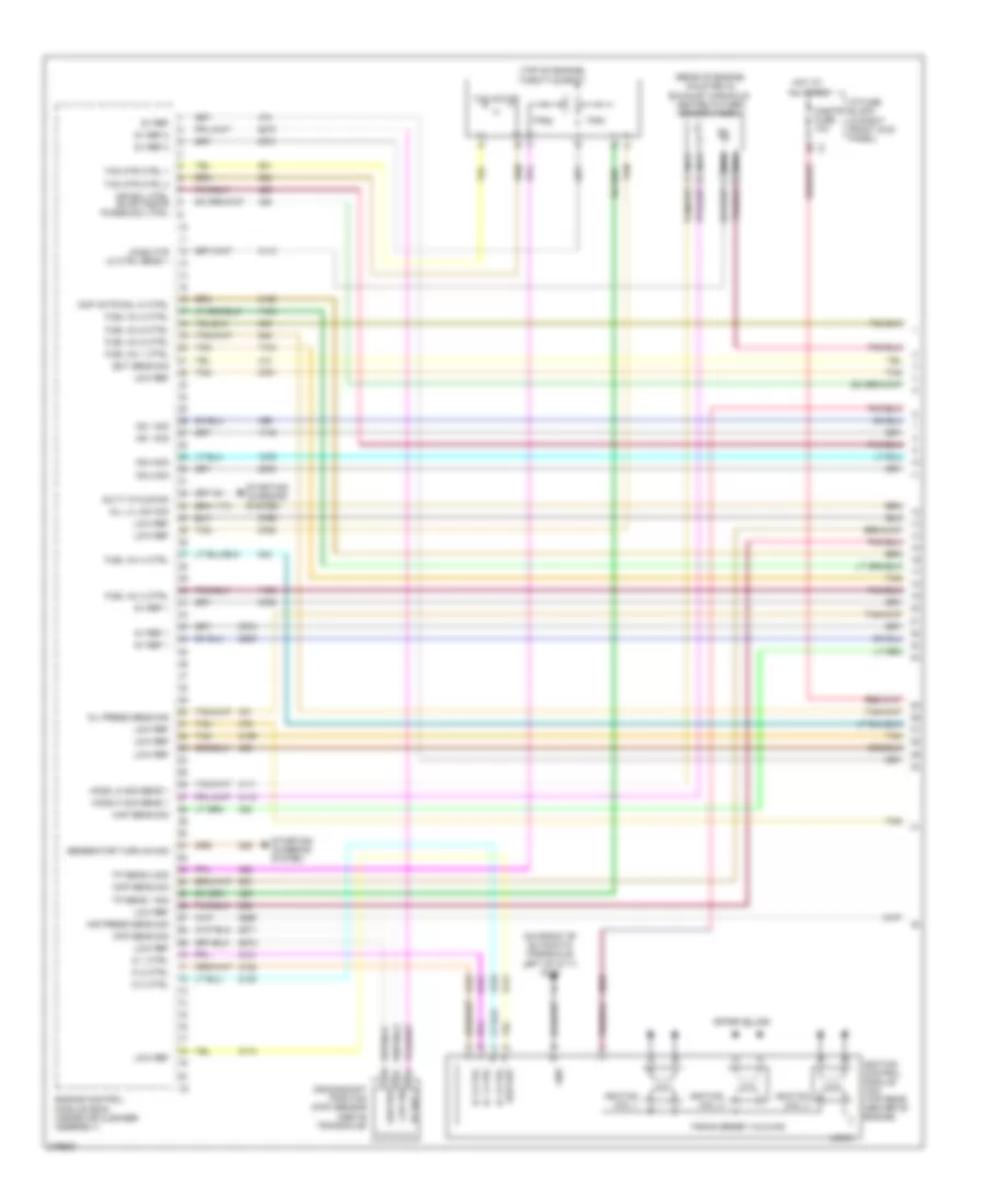
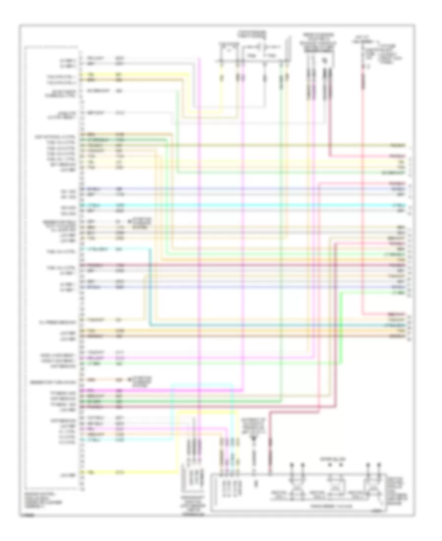
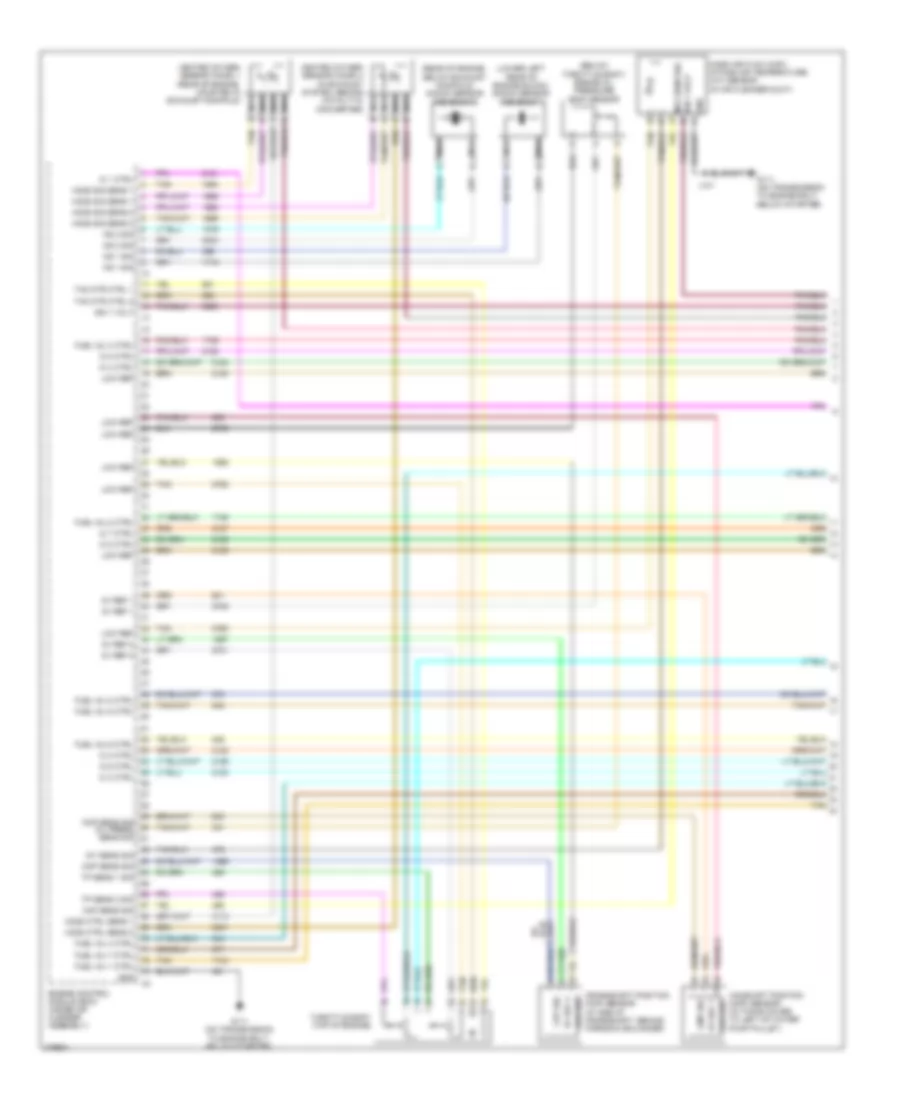
3.5L VIN K, Engine Performance Wiring Diagram (1 of 4) for Chevrolet Impala LS 2008
 https://portal-diagnostov.com/license.html
Automotive Electricians Portal FZCO
Automotive Electricians Portal FZCO
https://portal-diagnostov.com/license.html
https://portal-diagnostov.com/license.html
Automotive Electricians Portal FZCO
Automotive Electricians Portal FZCOList of elements for 3.5L VIN K, Engine Performance Wiring Diagram (1 of 4) for Chevrolet Impala LS 2008:
- (on front of automatic transaxle, left of g111) g113
- (rear of engine, mounted in exhaust manifold) heated oxygen sensor (ho2s) 1
- (top of engine) throttle body
- 5v ref
- 5v ref 1
- 5v ref 2
- Air press sens sig
- Air sol ctrl evap cnstr purge sol ctrl
- Ckp sens sig
- Ckp sig
- Cmp actr sol hi ctrl
- Cmp sens sig
- Cnstr fuse 10a
- Crankshaft position (ckp) sensor (above transaxle)
- Duty cycle sig
- Ect sens sig
- Engine control module (ecm) (inside air cleaner assembly)
- Firing order 1-2-3-4-5-6
- Fuel inj 1 ctrl
- Fuel inj 2 ctrl
- Fuel inj 3 ctrl
- Fuel inj 4 ctrl
- Fuel inj 5 ctrl
- Fuel inj 6 ctrl
- Generator turn on sig
- Gnd
- Ho2s hi sig sens 1
- Ho2s htr lo ctrl sens 1
- Ho2s lo sig sens 1
- Hot at all times
- I/p fuse block (in right front kick panel)
- Ic 1 ctrl
- Ic 2 ctrl
- Ic 3 ctrl
- Ignition coil 1
- Ignition coil 2
- Ignition coil 3
- Ignition control module (icm) (top rear center of engine)
- Ks 1 sig
- Ks 2 sig
- Logic
- Low ref
- Map sens sig
- Nca
- Oil lvl sw sig
- Oil press sens sig
- Spark plugs
- Starting/ charging system
- Tac motor
- Tac mtr ctrl 1
- Tac mtr ctrl 2
- Tan
- Tp sens 1 sig
- Tp sens 2 sig
- Tps1
- Tps2
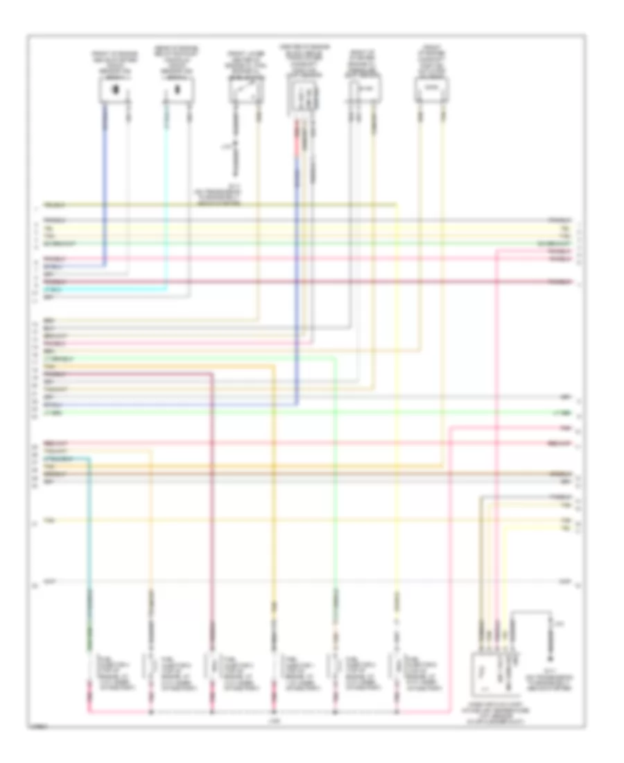
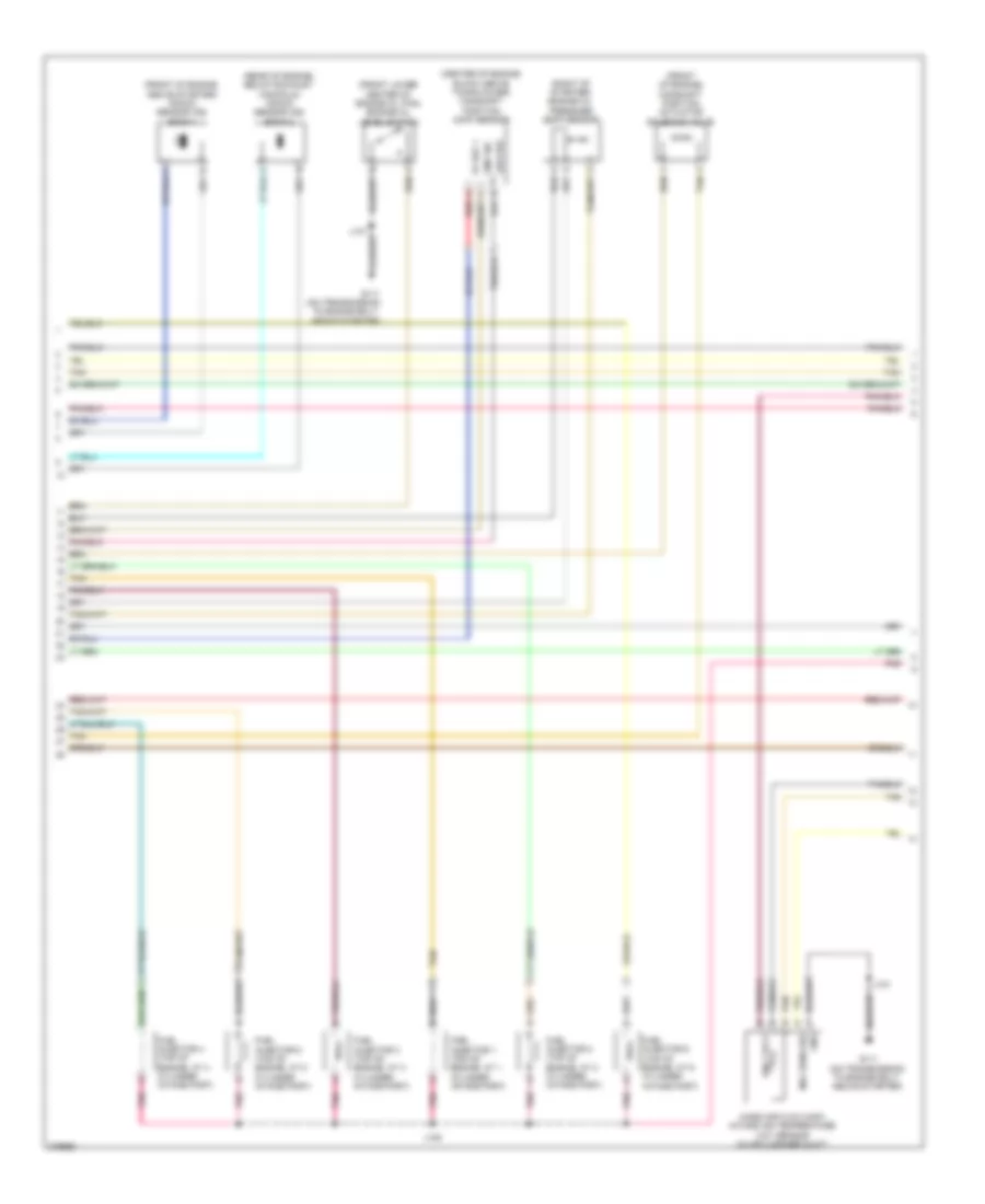
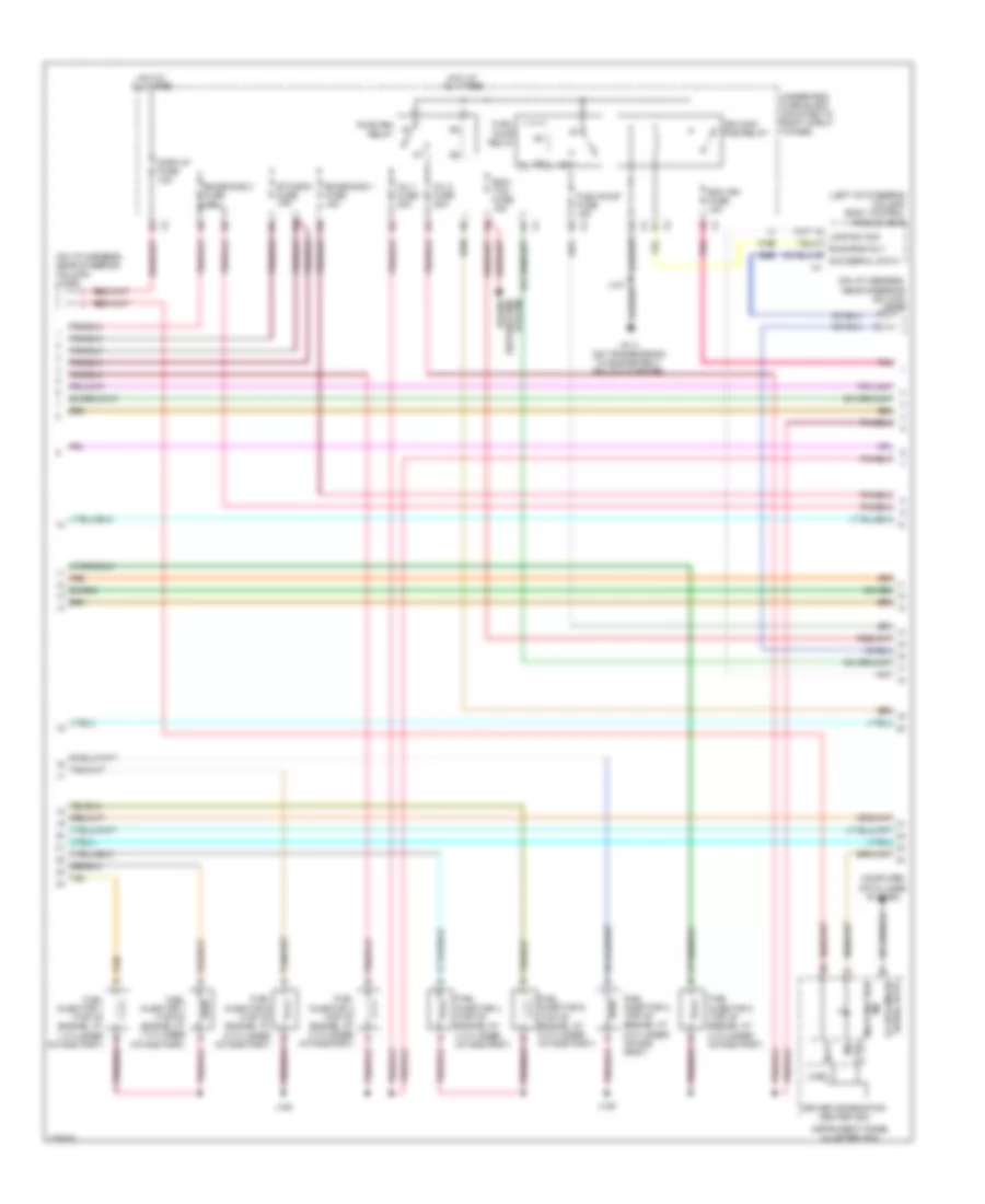
3.5L VIN K, Engine Performance Wiring Diagram (2 of 4) for Chevrolet Impala LS 2008
 https://portal-diagnostov.com/license.html
Automotive Electricians Portal FZCO
Automotive Electricians Portal FZCO
https://portal-diagnostov.com/license.html
https://portal-diagnostov.com/license.html
Automotive Electricians Portal FZCO
Automotive Electricians Portal FZCOList of elements for 3.5L VIN K, Engine Performance Wiring Diagram (2 of 4) for Chevrolet Impala LS 2008:
- (center of engine
- (front lower center of engine oil pan) engine oil level switch
- (front of engine)
- (front of engine, above starter) knock sensor (ks) bank 1
- (rear of engine, below exhaust manifold) knock sensor (ks) bank 2
- (right of starter)
- 5v ref 1
- A red
- Block above timing cover)
- Camshaft position (cmp) sensor
- Camshaft position actuator solenoid
- Cmp sig
- Engine oil pressure (eop) sensor
- Fuel injector 1 (top of engine, at 1 cylinder intake port)
- Fuel injector 2 (top of engine, at 2 cylinder intake port)
- Fuel injector 3 (top of engine, at 3 cylinder intake port)
- Fuel injector 4 (top of engine, at 4 cylinder intake port)
- Fuel injector 5 (top of engine, at 5 cylinder intake port)
- Fuel injector 6 (top of engine, at 6 cylinder intake port)
- G111 (on transmission to engine bolt, above starter)
- Gnd
- Ign 1 volt
- J101
- J109
- Low ref
- Maf sens sig
- Mass air flow (maf)/ intake air temperature (iat) sensor (in air cleaner duct)
- Pnk
- Tan
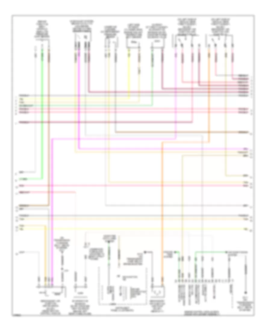
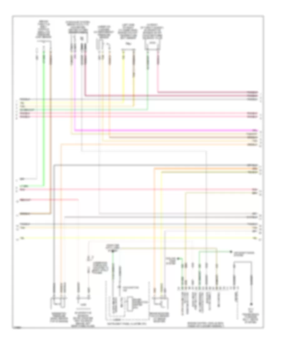
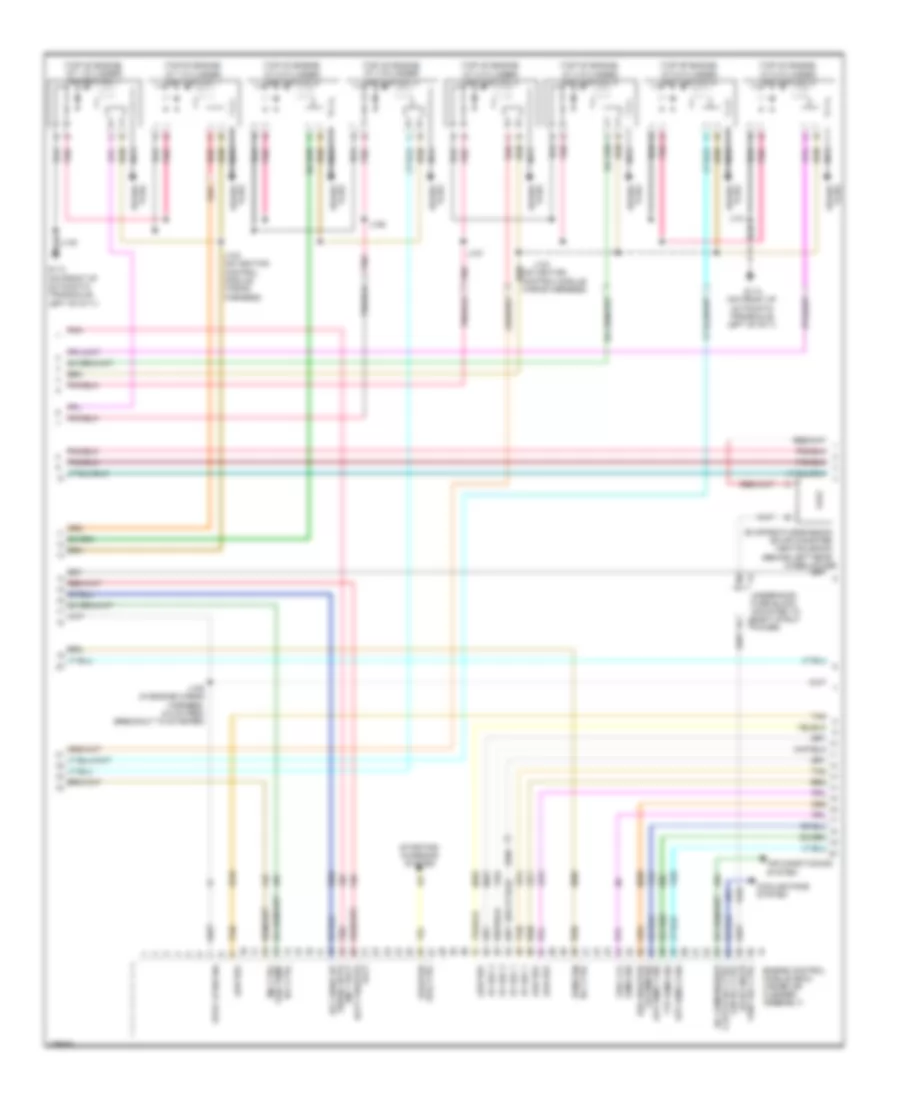
3.5L VIN K, Engine Performance Wiring Diagram (3 of 4) for Chevrolet Impala LS 2008
 https://portal-diagnostov.com/license.html
Automotive Electricians Portal FZCO
Automotive Electricians Portal FZCO
https://portal-diagnostov.com/license.html
https://portal-diagnostov.com/license.html
Automotive Electricians Portal FZCO
Automotive Electricians Portal FZCOList of elements for 3.5L VIN K, Engine Performance Wiring Diagram (3 of 4) for Chevrolet Impala LS 2008:
- (behind throttle body) manifold absolute pressure (map) sensor
- (in exhaust system, behind catalytic converter) heated oxygen sensor (ho2s) 2
- (in front of throttle body) evaporative emission (evap) canister purge solenoid valve
- (left side of front cylinder head) engine coolant temperature (ect) sensor
- (on left side of vehicle, near throttle body) (sulev) secondary air injection (air) pump relay
- (on left side of vehicle, near throttle body) (sulev) secondary air injection (air) solenoid relay
- (on transmission to engine bolt, above starter) g111
- (under air cleaner) a/c refrigerant pressure sensor
- Air conditioning system
- Clutch rly ctrl a/c compressor
- Computer data lines system
- Cooling fans system
- Driver information center (dic)
- Engine control module (ecm) (inside air cleaner assembly)
- Evaporative emission (evap) canister vent solenoid (behind left rear wheelhouse)
- Fan rly ctrl pwr/trn rly ctrl
- G111 (on transmission to engine bolt, above starter)
- G115 (on transmission case, below brake booster)
- Ground
- Ho2s htr
- Instrument panel cluster(ipc)
- J101
- Lo ctrl sens 2
- Lo spd cooling
- Logic
- Malfunction ind
- Mil control
- Mil ctrl
- Nca
- Pnk
- Sencondary air injection (air) pump (sulev) (near g111)
- Sencondary air injection (air) solenoid (sulev) (near ignition control module)
- Serial data gmlan lo spd
- Sol ctrl evap cnstr vent
- Tan
- Underhood fuse block (mounted to right strut x4 tower)
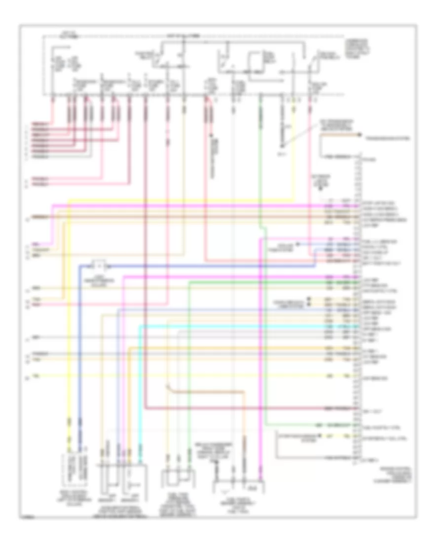
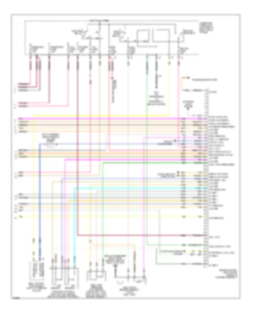
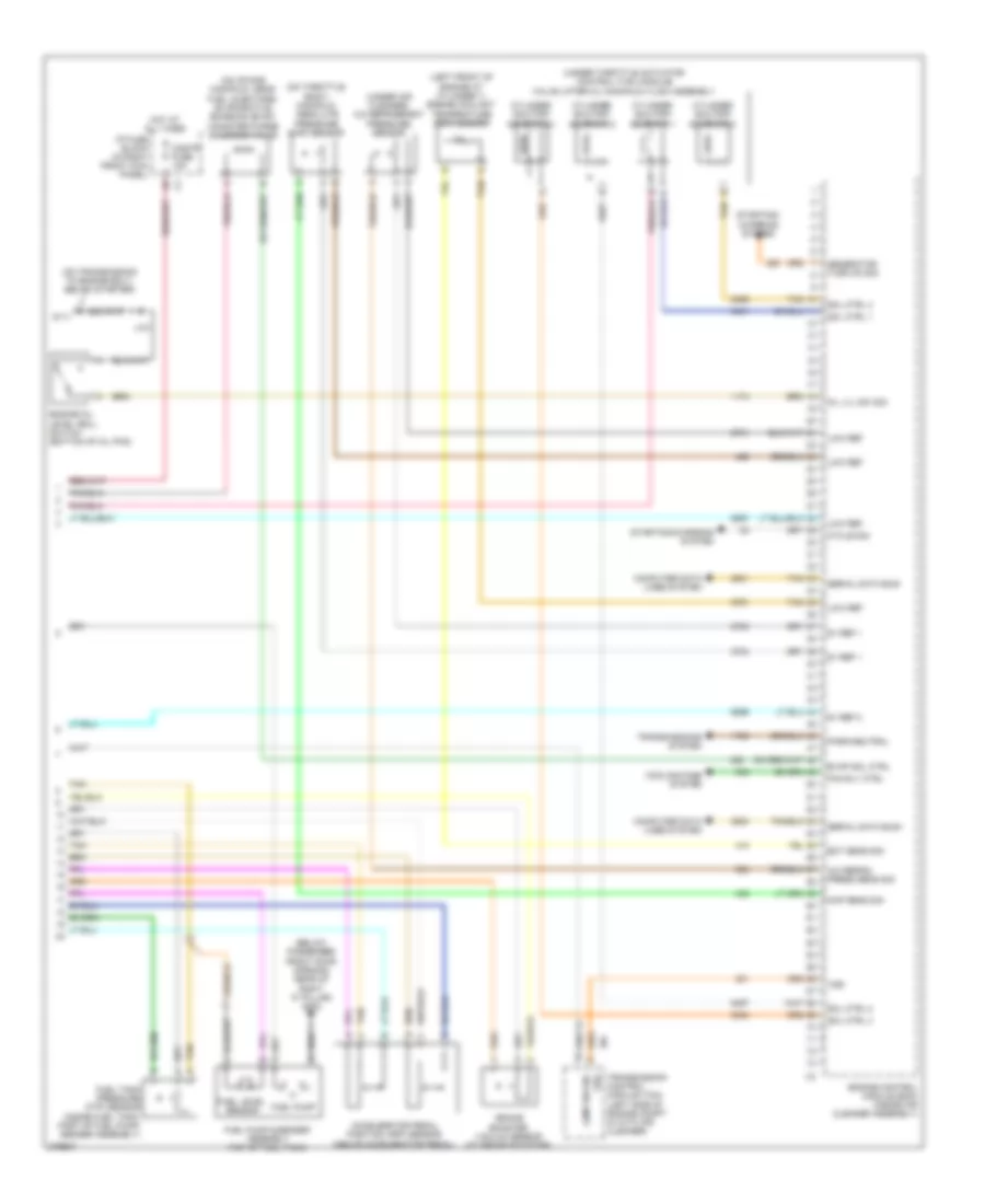
3.5L VIN K, Engine Performance Wiring Diagram (4 of 4) for Chevrolet Impala LS 2008
 https://portal-diagnostov.com/license.html
Automotive Electricians Portal FZCO
Automotive Electricians Portal FZCO
https://portal-diagnostov.com/license.html
https://portal-diagnostov.com/license.html
Automotive Electricians Portal FZCO
Automotive Electricians Portal FZCOList of elements for 3.5L VIN K, Engine Performance Wiring Diagram (4 of 4) for Chevrolet Impala LS 2008:
- (below passenger front door opening, rear of right "a" pillar) g302
- (on transmission to engine bolt, above starter)
- 5v ref 1
- 5v ref 2
- A/c refrig press sens
- Acc wake up
- Accelerator pedal position (app) sensor (above accelerator pedal)
- Air pump fuse 60a
- Air pump rly ctrl
- Air sol fuse 15a
- App sens 1 sig
- App sens 2 sig
- App sensor 1
- App sensor 2
- Batt positive volt
- Body control module (bcm) (left of steering column)
- Coil ctrl
- Computer data lines system
- Cooling fans system
- Ecm ign fuse 10a
- Ecm/ tcm fuse 15a
- Emissions 1 fuse 15a
- Emissions 2 fuse 15a
- Engine control module (ecm) (inside air cleaner assembly)
- Etc/ecm fuse 15a
- Exterior lights system
- Fan rly ctrl
- Ftp sens sig
- Fuel lvl sens sig
- Fuel pump & sender assembly (top of fuel tank)
- Fuel pump rly ctrl
- Fuel tank pressure (ftp) sensor (inside fuel tank, part of fuel pump/ sender assembly)
- Fuel/ pump fuse 15a
- Fuel/ pump relay
- G111
- Ho2s hi sig sens 2
- Ho2s lo sig sens 2
- Hot at all times
- Iat sens sig
- Ign 1 volt
- Ign main pcb relay
- Inj 1 fuse 20a
- Inj 2 fuse 20a
- Jx207 (near steering column)
- Low ref
- Maf sens sig
- P/n sig
- Pnk
- Power distribution system
- Pwr/trn relay
- Run/crnk rly
- Serial data bus+
- Serial data bus-
- Starter rly coil ctrl
- Starting/charging system
- Stop lmp sw sig
- Tan
- Transmissions system
- Underhood fuse block (mounted to right strut tower)
- X4 serial data acc wakeup
3.5L VIN N
3.5L VIN N, Engine Performance Wiring Diagram (1 of 4) for Chevrolet Impala LS 2008
 https://portal-diagnostov.com/license.html
Automotive Electricians Portal FZCO
Automotive Electricians Portal FZCO
https://portal-diagnostov.com/license.html
https://portal-diagnostov.com/license.html
Automotive Electricians Portal FZCO
Automotive Electricians Portal FZCOList of elements for 3.5L VIN N, Engine Performance Wiring Diagram (1 of 4) for Chevrolet Impala LS 2008:
- (on front of automatic transaxle, left of g111) g113
- (rear of engine, mounted in exhaust manifold) heated oxygen sensor (ho2s) 1
- (top of engine) throttle body
- 5v ref
- 5v ref 1
- 5v ref 2
- Air press sens sig
- Air sol ctrl evap cnstr purge sol ctrl
- Ckp sens sig
- Ckp sig
- Cmp actr sol hi ctrl
- Cmp sens sig
- Cnstr fuse 10a
- Crankshaft position (ckp) sensor (above transaxle)
- Duty cycle sig
- Ect sens sig
- Engine control module (ecm) (inside air cleaner assembly)
- Firing order 1-2-3-4-5-6
- Fuel inj 1 ctrl
- Fuel inj 2 ctrl
- Fuel inj 3 ctrl
- Fuel inj 4 ctrl
- Fuel inj 5 ctrl
- Fuel inj 6 ctrl
- Generator turn on sig
- Gnd
- Ho2s hi sig sens 1
- Ho2s htr lo ctrl sens 1
- Ho2s lo sig sens 1
- Hot at all times
- I/p fuse block (in right front kick panel)
- Ic 1 ctrl
- Ic 2 ctrl
- Ic 3 ctrl
- Ignition coil 1
- Ignition coil 2
- Ignition coil 3
- Ignition control module (icm) (top rear center of engine)
- Ks 1 sig
- Ks 2 sig
- Logic
- Low ref
- Map sens sig
- Nca
- Oil lvl sw sig
- Oil press sens sig
- Spark plugs
- Starting/ charging system
- Tac motor
- Tac mtr ctrl 1
- Tac mtr ctrl 2
- Tan
- Tp sens 1 sig
- Tp sens 2 sig
- Tps1
- Tps2
3.5L VIN N, Engine Performance Wiring Diagram (2 of 4) for Chevrolet Impala LS 2008
 https://portal-diagnostov.com/license.html
Automotive Electricians Portal FZCO
Automotive Electricians Portal FZCO
https://portal-diagnostov.com/license.html
https://portal-diagnostov.com/license.html
Automotive Electricians Portal FZCO
Automotive Electricians Portal FZCOList of elements for 3.5L VIN N, Engine Performance Wiring Diagram (2 of 4) for Chevrolet Impala LS 2008:
- (center of engine
- (front lower center of engine oil pan) engine oil level switch
- (front of engine)
- (front of engine, above starter) knock sensor (ks) bank 1
- (rear of engine, below exhaust manifold) knock sensor (ks) bank 2
- (right of starter)
- 5v ref 1
- A red
- Block above timing cover)
- Camshaft position (cmp) sensor
- Camshaft position actuator solenoid
- Cmp sig
- Engine oil pressure (eop) sensor
- Fuel injector 1 (top of engine, at 1 cylinder intake port)
- Fuel injector 2 (top of engine, at 2 cylinder intake port)
- Fuel injector 3 (top of engine, at 3 cylinder intake port)
- Fuel injector 4 (top of engine, at 4 cylinder intake port)
- Fuel injector 5 (top of engine, at 5 cylinder intake port)
- Fuel injector 6 (top of engine, at 6 cylinder intake port)
- G111 (on transmission to engine bolt, above starter)
- Gnd
- Ign 1 volt
- J101
- J109
- Low ref
- Maf sens sig
- Mass air flow (maf)/ intake air temperature (iat) sensor (in air cleaner duct)
- Pnk
- Tan
3.5L VIN N, Engine Performance Wiring Diagram (3 of 4) for Chevrolet Impala LS 2008
 https://portal-diagnostov.com/license.html
Automotive Electricians Portal FZCO
Automotive Electricians Portal FZCO
https://portal-diagnostov.com/license.html
https://portal-diagnostov.com/license.html
Automotive Electricians Portal FZCO
Automotive Electricians Portal FZCOList of elements for 3.5L VIN N, Engine Performance Wiring Diagram (3 of 4) for Chevrolet Impala LS 2008:
- (behind throttle body) manifold absolute pressure (map) sensor
- (in exhaust system, behind catalytic converter) heated oxygen sensor (ho2s) 2
- (in front of throttle body) evaporative emission (evap) canister purge solenoid valve
- (left side of front cylinder head) engine coolant temperature (ect) sensor
- (on left side of vehicle, near throttle body) (sulev) secondary air injection (air) pump relay
- (on left side of vehicle, near throttle body) (sulev) secondary air injection (air) solenoid relay
- (on transmission to engine bolt, above starter) g111
- (under air cleaner) a/c refrigerant pressure sensor
- Air conditioning system
- Clutch rly ctrl a/c compressor
- Computer data lines system
- Cooling fans system
- Driver information center (dic)
- Engine control module (ecm) (inside air cleaner assembly)
- Evaporative emission (evap) canister vent solenoid (behind left rear wheelhouse)
- Fan rly ctrl pwr/trn rly ctrl
- G111 (on transmission to engine bolt, above starter)
- G115 (on transmission case, below brake booster)
- Ground
- Ho2s htr
- Instrument panel cluster(ipc)
- J101
- Lo ctrl sens 2
- Lo spd cooling
- Logic
- Malfunction ind
- Mil control
- Mil ctrl
- Nca
- Pnk
- Sencondary air injection (air) pump (sulev) (near g111)
- Sencondary air injection (air) solenoid (sulev) (near ignition control module)
- Serial data gmlan lo spd
- Sol ctrl evap cnstr vent
- Tan
- Underhood fuse block (mounted to right strut x4 tower)
3.5L VIN N, Engine Performance Wiring Diagram (4 of 4) for Chevrolet Impala LS 2008
 https://portal-diagnostov.com/license.html
Automotive Electricians Portal FZCO
Automotive Electricians Portal FZCO
https://portal-diagnostov.com/license.html
https://portal-diagnostov.com/license.html
Automotive Electricians Portal FZCO
Automotive Electricians Portal FZCOList of elements for 3.5L VIN N, Engine Performance Wiring Diagram (4 of 4) for Chevrolet Impala LS 2008:
- (below passenger front door opening, rear of right "a" pillar) g302
- (on transmission to engine bolt, above starter)
- 5v ref 1
- 5v ref 2
- A/c refrig press sens
- Acc wake up
- Accelerator pedal position (app) sensor (above accelerator pedal)
- Air pump fuse 60a
- Air pump rly ctrl
- Air sol fuse 15a
- App sens 1 sig
- App sens 2 sig
- App sensor 1
- App sensor 2
- Batt positive volt
- Body control module (bcm) (left of steering column)
- Coil ctrl
- Computer data lines system
- Cooling fans system
- Ecm ign fuse 10a
- Ecm/ tcm fuse 15a
- Emissions 1 fuse 15a
- Emissions 2 fuse 15a
- Engine control module (ecm) (inside air cleaner assembly)
- Etc/ecm fuse 15a
- Exterior lights system
- Fan rly ctrl
- Ftp sens sig
- Fuel lvl sens sig
- Fuel pump & sender assembly (top of fuel tank)
- Fuel pump rly ctrl
- Fuel tank pressure (ftp) sensor (inside fuel tank, part of fuel pump/ sender assembly)
- Fuel/ pump fuse 15a
- Fuel/ pump relay
- G111
- Ho2s hi sig sens 2
- Ho2s lo sig sens 2
- Hot at all times
- Iat sens sig
- Ign 1 volt
- Ign main pcb relay
- Inj 1 fuse 20a
- Inj 2 fuse 20a
- Jx207 (near steering column)
- Low ref
- Maf sens sig
- P/n sig
- Pnk
- Power distribution system
- Pwr/trn relay
- Run/crnk rly
- Serial data bus+
- Serial data bus-
- Starter rly coil ctrl
- Starting/charging system
- Stop lmp sw sig
- Tan
- Transmissions system
- Underhood fuse block (mounted to right strut tower)
- X4 serial data acc wakeup
3.9L VIN 3
3.9L VIN 3, Engine Performance Wiring Diagram (1 of 4) for Chevrolet Impala LS 2008
 https://portal-diagnostov.com/license.html
Automotive Electricians Portal FZCO
Automotive Electricians Portal FZCO
https://portal-diagnostov.com/license.html
https://portal-diagnostov.com/license.html
Automotive Electricians Portal FZCO
Automotive Electricians Portal FZCOList of elements for 3.9L VIN 3, Engine Performance Wiring Diagram (1 of 4) for Chevrolet Impala LS 2008:
- (on front of automatic transaxle, left of g111) g113
- (rear of engine, mounted in exhaust manifold) heated oxygen sensor (ho2s) 1
- (top of engine) throttle body
- 5v ref 1
- 5v ref 2
- Ckp sens sig
- Ckp sig
- Cmp actr sol hi ctrl
- Cmp sens sig
- Cnstr fuse 10a
- Crankshaft position (ckp) sensor (above transaxle)
- Ect sens sig
- Engine control module (ecm) (inside air cleaner assembly)
- Evap cnstr purge sol ctrl
- Firing order 1-2-3-4-5-6
- Fuel inj 1 ctrl
- Fuel inj 2 ctrl
- Fuel inj 3 ctrl
- Fuel inj 4 ctrl
- Fuel inj 5 ctrl
- Fuel inj 6 ctrl
- Generator field duty cycle sig oil le sw sig
- Generator turn on sig
- Gnd
- Ho2s hi sig sens 1
- Ho2s htr lo ctrl sens 1
- Ho2s lo sig sens 1
- Hot at all times
- I/p fuse block (in right front kick panel)
- Ic 1 ctrl
- Ic 2 ctrl
- Ic 3 ctrl
- Ignition coil 1
- Ignition coil 2
- Ignition coil 3
- Ignition control module (icm) (top rear center of engine)
- Ks 1 sig
- Ks 2 sig
- Logic
- Low ref
- Map sens sig
- Nca
- Oil press sens sig
- Spark plugs
- Starting/ charging system
- Tac motor
- Tac mtr ctrl 1
- Tac mtr ctrl 2
- Tan
- Tp sens 1 sig
- Tp sens 2 sig
- Tps1
- Tps2
3.9L VIN 3, Engine Performance Wiring Diagram (2 of 4) for Chevrolet Impala LS 2008
 https://portal-diagnostov.com/license.html
Automotive Electricians Portal FZCO
Automotive Electricians Portal FZCO
https://portal-diagnostov.com/license.html
https://portal-diagnostov.com/license.html
Automotive Electricians Portal FZCO
Automotive Electricians Portal FZCOList of elements for 3.9L VIN 3, Engine Performance Wiring Diagram (2 of 4) for Chevrolet Impala LS 2008:
- (center of engine block above timing cover) camshaft position (cmp) sensor
- (front lower center of engine oil pan) engine oil level switch
- (front of engine) camshaft position actuator solenoid valve
- (front of engine, above starter) knock sensor (ks) bank 1
- (rear of engine, below exhaust manifold) knock sensor (ks) bank 2
- (right of starter) engine oil pressure (eop) sensor
- 5v ref 1
- A red
- B ign 1 volt
- C gnd
- Cmp sig
- Fuel injector 1 (top of engine, at 1 cylinder intake port)
- Fuel injector 2 (top of engine, at 2 cylinder intake port)
- Fuel injector 3 (top of engine, at 3 cylinder intake port)
- Fuel injector 4 (top of engine, at 4 cylinder intake port)
- Fuel injector 5 (top of engine, at 5 cylinder intake port)
- Fuel injector 6 (top of engine, at 6 cylinder intake port)
- G111 (on transmission to engine bolt, above starter)
- J101
- J109
- Low ref
- Maf sens sig
- Mass air flow (maf)/ intake air temperature (iat) sensor (in air cleaner duct)
- Pnk
- Tan
3.9L VIN 3, Engine Performance Wiring Diagram (3 of 4) for Chevrolet Impala LS 2008
 https://portal-diagnostov.com/license.html
Automotive Electricians Portal FZCO
Automotive Electricians Portal FZCO
https://portal-diagnostov.com/license.html
https://portal-diagnostov.com/license.html
Automotive Electricians Portal FZCO
Automotive Electricians Portal FZCOList of elements for 3.9L VIN 3, Engine Performance Wiring Diagram (3 of 4) for Chevrolet Impala LS 2008:
- (behind throttle body) manifold absolute pressure (map) sensor
- (in exhaust system, behind catalytic converter) heated oxygen sensor (ho2s) 2
- (in front of throttle body) evaporative emission (evap) canister purge solenoid valve
- (left side of front cylinder head) engine coolant temperature (ect) sensor
- (under air cleaner) a/c refrigerant pressure sensor
- Air conditioning system
- Barometric pressure (baro) sensor (top of engine)
- Brake booster vacuum sensor (at brake booster)
- Clutch rly ctrl a/c compressor
- Computer data lines system
- Cooling fans system
- Driver information center (dic)
- Engine control module (ecm) (inside air cleaner assembly)
- Evaporative emission (evap) canister vent solenoid (behind left rear wheelhouse)
- G111 (on transmission to engine bolt, above starter)
- Ground
- Instrument panel cluster (ipc)
- Lo ctrl sens 2 ho2s htr
- Lo spd cooling fan
- Logic
- Malfunction ind
- Mil control
- Mil ctrl
- Nca
- Pnk
- Rly ctrl pwr/trn rly ctrl
- Serial data lo spd gmlan
- Tan
- Underhood fuse block (mounted to right strut x4 tower)
- Vent sol ctrl evap cnstr
3.9L VIN 3, Engine Performance Wiring Diagram (4 of 4) for Chevrolet Impala LS 2008
 https://portal-diagnostov.com/license.html
Automotive Electricians Portal FZCO
Automotive Electricians Portal FZCO
https://portal-diagnostov.com/license.html
https://portal-diagnostov.com/license.html
Automotive Electricians Portal FZCO
Automotive Electricians Portal FZCOList of elements for 3.9L VIN 3, Engine Performance Wiring Diagram (4 of 4) for Chevrolet Impala LS 2008:
- (below passenger front door opening, rear of right "a" pillar) g302
- (on i/p harness, near steering column) jx207
- 5v ref 1
- 5v ref 2
- A/c refrig press sens
- Above starter)
- Acc wake up
- Accelerator pedal position (app) sensor (above accelerator pedal)
- App sens 1 sig
- App sens 2 sig
- App sensor 1
- App sensor 2
- Baro sens sig
- Batt positive volt
- Body control module (bcm) (left of steering column)
- Brk booster vac sig
- Coil ctrl
- Computer data lines system
- Cooling fans system
- Ecm ign fuse 10a
- Ecm/ tcm fuse 15a
- Emissions 1 fuse 15a
- Emissions 2 fuse 15a
- Engine control module (ecm) (inside air cleaner assembly)
- Etc/ecm fuse 15a
- Exterior lights system
- Fan rly ctrl
- Fuel lvl sens sig
- Fuel pump & sender assembly (top of fuel tank)
- Fuel pump rly ctrl
- Fuel tank press sens
- Fuel tank pressure (ftp) sensor (inside fuel tank, part of fuel pump/ sender assembly)
- Fuel/ pump fuse 15a
- Fuel/ pump relay
- G111 (on transmission to engine bolt,
- Ho2s hi sig sens 2
- Ho2s lo sig sens 2
- Hot at all times
- Iat sens sig
- Ign 1 volt
- Ign main pcb relay
- Inj 1 fuse 20a
- Inj 2 fuse 20a
- Low ref
- Maf sens sig
- P/n sig
- Pnk
- Power distribution system
- Pwr/trn relay
- Run/crnk rly
- Serial data bus+
- Serial data bus-
- Starter rly coil ctrl
- Starting/charging system
- Stop lmp sw sig
- Tan
- Transmissions system
- Underhood fuse block (mounted to right strut tower)
- X4 serial data acc wakeup
5.3L VIN C
5.3L VIN C, Engine Performance Wiring Diagram (1 of 4) for Chevrolet Impala LS 2008
 https://portal-diagnostov.com/license.html
Automotive Electricians Portal FZCO
Automotive Electricians Portal FZCO
https://portal-diagnostov.com/license.html
https://portal-diagnostov.com/license.html
Automotive Electricians Portal FZCO
Automotive Electricians Portal FZCOList of elements for 5.3L VIN C, Engine Performance Wiring Diagram (1 of 4) for Chevrolet Impala LS 2008:
- (below throttle body) engine oil pressure (eop) sensor
- (lower left rear of engine block) knock sensor (ks) bank 1
- (rear of engine, below exhaust manifold) knock sensor (ks) bank 2
- 5v ref 1
- 5v ref 2
- A tan
- Camshaft position (cmp) sensor (in timing cover, to left of water pump pulley)
- Ckp sens sig
- Ckp sig
- Cmp sens sig oil press sens sig
- Cmp sig
- Crankshaft position (ckp) sensor (at end of crankshaft, behind harmonic balancer)
- Engine control module (ecm) (inside air cleaner assembly)
- Fuel inj 1 ctrl
- Fuel inj 2 ctrl
- Fuel inj 3 ctrl
- Fuel inj 4 ctrl
- Fuel inj 5 ctrl
- Fuel inj 6 ctrl
- Fuel inj 7 ctrl
- Fuel inj 8 ctrl
- G111 (on transmission to engine bolt, below starter)
- Gnd
- Gnd c
- Heated oxygen sensor (ho2s) 1 (rear of engine, mounted in exhaust manifold)
- Heated oxygen sensor (ho2s) 2 (in exhaust system, behind catalytic converter)
- Ho2s ctrl sens 1
- Ho2s ctrl sens 2
- Ho2s sig sens 1
- Ho2s sig sens 2
- Iat sens sig
- Ic 1 ctrl
- Ic 2 ctrl
- Ic 3 ctrl
- Ic 4 ctrl
- Ic 5 ctrl
- Ic 6 ctrl
- Ic 7 ctrl
- Ic 8 ctrl
- Ign 1 volt
- Ign 1 volt b
- J101
- Ks 1 sig
- Ks 2 sig
- Low ref
- Maf sens sig
- Maf sens sig a
- Mass air flow (maf)/ intake air temperature (iat) sensor (in air cleaner duct)
- Nca
- Tac mtr ctrl 1
- Tac mtr ctrl 2
- Tan
- Throttle body (top of engine)
- Tp sens 1 sig
- Tp sens 2 sig
5.3L VIN C, Engine Performance Wiring Diagram (2 of 4) for Chevrolet Impala LS 2008
 https://portal-diagnostov.com/license.html
Automotive Electricians Portal FZCO
Automotive Electricians Portal FZCO
https://portal-diagnostov.com/license.html
https://portal-diagnostov.com/license.html
Automotive Electricians Portal FZCO
Automotive Electricians Portal FZCOList of elements for 5.3L VIN C, Engine Performance Wiring Diagram (2 of 4) for Chevrolet Impala LS 2008:
- (left of steering column) body control module (bcm)
- (on i/p harness, near steering column) jx206
- (on i/p harness, near steering column) jx207
- Batt
- Computer data lines system
- Display fuse 10a
- Distribution power
- Driver information center (dic)
- Ecm ign fuse 10a
- Ecm/ tcm fuse 15a
- Emissions 1 fuse 15a
- Emissions 2 fuse 15a
- Etc/ecm fuse 15a
- Fuel injector 1 (top of engine, at 1 cylinder intake port)
- Fuel injector 2 (top of engine, at 2 cylinder intake port)
- Fuel injector 3 (top of engine, at 3 cylinder intake port)
- Fuel injector 4 (top of engine, at 4 cylinder intake port)
- Fuel injector 5 (top of engine, at 5 cylinder intake port)
- Fuel injector 6 (top of engine, at 6 cylinder intake port)
- Fuel injector 7 (top of engine, at 7 cylinder intake port)
- Fuel injector 8 (top of engine, at 8 cylinder intake port)
- Fuel/ pump relay
- Fuel/pump fuse 15a
- G111 (on transmission to engine bolt, below starter)
- Hot at all times
- Ign main pcb relay
- Inj 1 fuse 20a
- Inj 2 fuse 20a
- Instrument panel cluster (ipc)
- J108
- J109
- Logic
- Malfunction ind
- Mil ctrl
- Pnk
- Pwr/trn relay
- Serial data lo spd gmlan
- System
- Tan
- Underhood fuse block (mounted to right strut tower)
5.3L VIN C, Engine Performance Wiring Diagram (3 of 4) for Chevrolet Impala LS 2008
 https://portal-diagnostov.com/license.html
Automotive Electricians Portal FZCO
Automotive Electricians Portal FZCO
https://portal-diagnostov.com/license.html
https://portal-diagnostov.com/license.html
Automotive Electricians Portal FZCO
Automotive Electricians Portal FZCOList of elements for 5.3L VIN C, Engine Performance Wiring Diagram (3 of 4) for Chevrolet Impala LS 2008:
- (top of engine, at 1 cylinder) ignition coil 1
- (top of engine, at 2 cylinder) ignition coil 2
- (top of engine, at 3 cylinder) ignition coil 3
- (top of engine, at 4 cylinder) ignition coil 4
- (top of engine, at 5 cylinder) ignition coil 5
- (top of engine, at 6 cylinder) ignition coil 6
- (top of engine, at 7 cylinder) ignition coil 7
- (top of engine, at 8 cylinder) ignition coil 8
- 5v ref 1
- 5v ref 2
- A/c compressor
- Acc wake up serial data
- Air conditioning system
- App sens 2 sig
- Batt positive
- Brk booster
- Clutch rly ctrl fan rly ctrl
- Coil ctrl
- Cooling fans system
- Engine control module (ecm) (inside air cleaner assembly)
- Evap cnstr
- Evaporative emission (evap) canister vent solenoid (behind left rear
- Ftp sens sig
- Fuel lvl
- Fuel pump
- G113 (on front of automatic transaxle, left of g111)
- Ign 1 volt
- J105 (in engine wiring harness, 5.5 cm from breakout to starter)
- J106
- J107
- J130
- J131
- J132 (on ignition control module wiring harness)
- J133
- Low ref
- Mil ctrl
- Nca
- Plug spark
- Pnk
- Pwr/trn
- Red
- Rly ctrl
- Sens sig
- Spark plug
- Starter
- Starting/ charging system
- Stop lp sw sig
- Tan
- Underhood fuse block (mounted to right strut x1 tower)
- Vacuum sig app sens 1 sig
- Vent sol ctrl
- Volt
- Wheelhouse)
5.3L VIN C, Engine Performance Wiring Diagram (4 of 4) for Chevrolet Impala LS 2008
 https://portal-diagnostov.com/license.html
Automotive Electricians Portal FZCO
Automotive Electricians Portal FZCO
https://portal-diagnostov.com/license.html
https://portal-diagnostov.com/license.html
Automotive Electricians Portal FZCO
Automotive Electricians Portal FZCOList of elements for 5.3L VIN C, Engine Performance Wiring Diagram (4 of 4) for Chevrolet Impala LS 2008:
- (below passenger front door opening, rear of right "a" pillar) g302
- (left front of engine at cylinder 1) engine coolant temperature (ect) sensor
- (on intake manifold, near fuel injectors) evaporative emission (evap) canister purge solenoid valve
- (on throttle body) manifold absolute pressure (map) sensor
- (on transmission to engine bolt, below starter)
- (under air cleaner) a/c refrigerant pressure sensor
- (under throttle actuator control (tac) module) valve lifter oil manifold (vlom) assembly
- 5v ref 1
- 5v ref 2
- A/c refrig press sens sig
- Accelerator pedal position (app) sensor (above accelerator pedal)
- B tan
- Brake booster vacuum sensor (at brake booster)
- Cnstr fuse 10a
- Computer data lines system
- Cooling fans system
- Cycle sig
- Cylinder shutoff solenoid 1
- Cylinder shutoff solenoid 2
- Cylinder shutoff solenoid 3
- Cylinder shutoff solenoid 4
- Ect sens sig
- Engine control module (ecm) (inside air cleaner assembly)
- Engine oil level (eol) switch (bottom of oil pan)
- Evap sol ctrl
- Fan rly ctrl
- Fuel level sensor
- Fuel pump
- Fuel pump & sender assembly (top of fuel tank)
- Fuel tank pressure (ftp) sensor (inside fuel tank, part of fuel pump/ sender assembly)
- G111
- Generator turn on sig
- Hot at all times
- I/p fuse block (in right front kick panel)
- J101
- Lamp sw sig
- Low ref
- Map sens sig
- Oil lvl sw sig
- Park/neutral
- Serial data bus+
- Serial data bus-
- Sol ctrl 1
- Sol ctrl 2
- Sol ctrl 3
- Sol ctrl 4
- Starting/ charging system
- Starting/charging system
- Tan
- Transmission control module (tcm) (left side of engine compt in with air cleaner)
- Transmissions system
- Vss
EXTERIOR LIGHTS
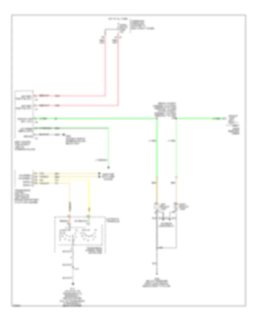
Backup Lamps Wiring Diagram for Chevrolet Impala LS 2008
 https://portal-diagnostov.com/license.html
Automotive Electricians Portal FZCO
Automotive Electricians Portal FZCO
https://portal-diagnostov.com/license.html
https://portal-diagnostov.com/license.html
Automotive Electricians Portal FZCO
Automotive Electricians Portal FZCOList of elements for Backup Lamps Wiring Diagram for Chevrolet Impala LS 2008:
- (sedan: on body harness, 24 cm from breakout to x405) (coupe: on body harness, 7 cm from breakout to x405) j324
- Automatic transaxle
- Backup lamp sply volt
- Battery positive volt
- Body control module (bcm) (left of steering column)
- Chmsl/ bck-up fuse 10a
- Computer data lines system
- Exterior lamps circuit
- G111 (3.5l & 3.9l: on transmission to engine bolt, above starter) (5.3l: on transmission to engine bolt, below starter)
- G202 (on right side of steering column below x201)
- G302 (below passenger front door opening, rear of right "a" pillar)
- Ground
- Hig speed (+)
- Hig speed (-)
- Hot at all times
- Inside rearview mirror
- J101
- J485
- Left backup lamp
- Logic
- Low speed serial data
- Right backup lamp
- Signal a
- Signal b
- Tan
- Transmission control module (tcm) (left side of engine compartment in with air cleaner)
- Transmission internal mode switch (ims)
- Underhood fuse block (mounted to right strut tower)
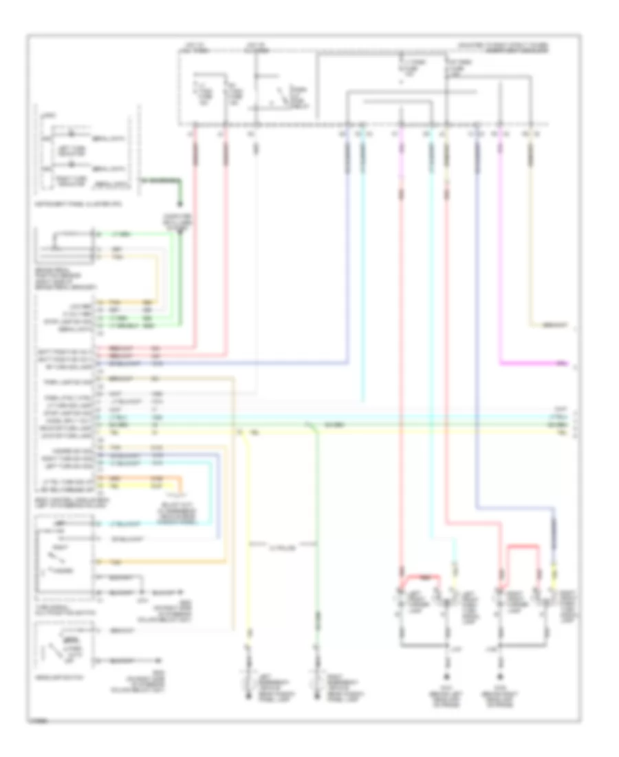
Exterior Lamps Wiring Diagram (1 of 2) for Chevrolet Impala LS 2008
 https://portal-diagnostov.com/license.html
Automotive Electricians Portal FZCO
Automotive Electricians Portal FZCO
https://portal-diagnostov.com/license.html
https://portal-diagnostov.com/license.html
Automotive Electricians Portal FZCO
Automotive Electricians Portal FZCOList of elements for Exterior Lamps Wiring Diagram (1 of 2) for Chevrolet Impala LS 2008:
- (mounted to right strut tower) underhood fuse block
- 5 volt ref
- Auto
- Batt positive volt
- Body control module (bcm) (left of steering column)
- Brake pedal position sensor (right side of brake pedal bracket)
- Chmsl sply volt
- Computer data lines system
- G100 (behind right headlamp, on frame)
- G101 (behind left headlamp, on frame)
- G202 (on right side of steering column below x201)
- Hazard
- Hazard sw sig
- Head
- Headlamp switch
- Hot at all times
- Ign
- Instrument panel cluster (ipc)
- J126
- J127
- J214
- Left
- Left emergency vehicle rear window panel lamp
- Left front marker lamp
- Left front park/ turn signal lamp
- Left turn indicator
- Left turn sw sig
- Lf trl turn sig lp
- Lf turn sig lamp
- Logic
- Low ref
- Lr stop/turn lamp
- Lt park fuse 10a
- Lt t/sig fuse 15a
- Nca
- Off
- Park
- Park lamp sw sig
- Park lp pcb relay
- Park lp rly ctrl
- Red
- Rf turn sig lamp
- Right
- Right emergency vehicle rear window panel lamp
- Right front marker lamp
- Right front park/ turn signal lamp
- Right turn indicator
- Right turn sw sig
- Rr stop/turn lamp
- Rt park fuse 10a
- Rt t/sig fuse 15a
- Rt trl turn sig lp
- Serial data
- Stop lamp sw sig
- Tan
- Turn signal/ multifunction switch
- W/ police
- X2 c2
- X2 k5
- X2 k6
- X3 c1
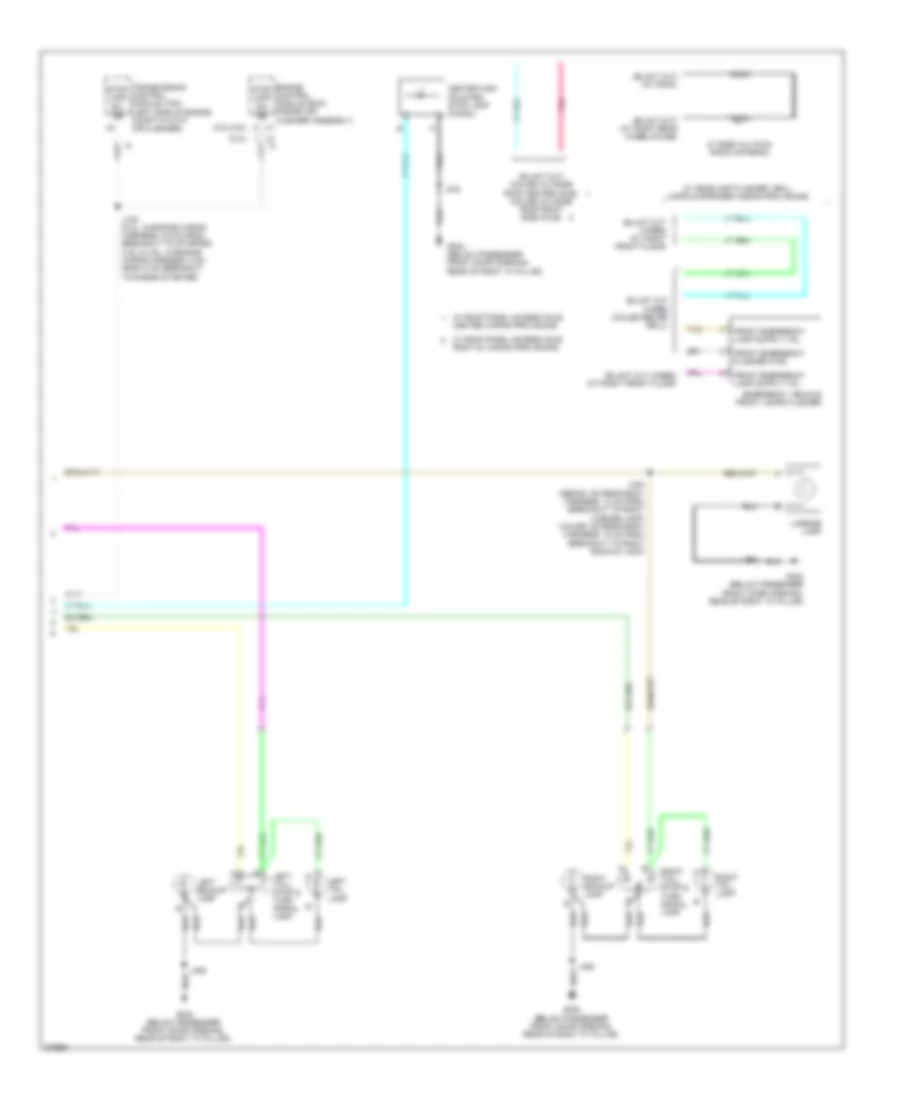
Exterior Lamps Wiring Diagram (2 of 2) for Chevrolet Impala LS 2008
 https://portal-diagnostov.com/license.html
Automotive Electricians Portal FZCO
Automotive Electricians Portal FZCO
https://portal-diagnostov.com/license.html
https://portal-diagnostov.com/license.html
Automotive Electricians Portal FZCO
Automotive Electricians Portal FZCOList of elements for Exterior Lamps Wiring Diagram (2 of 2) for Chevrolet Impala LS 2008:
- (3.5l/3.9l)
- (5.3l)
- Center high mounted stop lamp (chmsl)
- Coax
- Emergency vehicle front lamps flasher
- Engine control module (ecm) (inside air cleaner assembly)
- Front emergency flasher ctrl
- G302 (below passenger front door opening, rear of right "a" pillar)
- J105 (5.3l: in engine wiring harness, 5.5 cm from breakout to starter) (3.5l & 3.9l: in engine wiring harness, 5 cm from x100 breakout towards starter)
- J375
- J430 (sedan: on rear body harness, 14 cm from breakout to right license lamp) (coupe: on rear body harness, 10 cm from breakout to right backup lamp)
- J485
- Left backup lamp
- Left tail lamp
- Left tail/ stop & turn signal lamp
- License lamp
- Pnk
- Right backup lamp
- Right tail lamp
- Right tail/ stop & turn signal lamp
- Stop lamp sw sig
- Tan
- Transmission control module (tcm) (left side of engine compt in with air cleaner)
- W/ headlamp flasher, grill lamps & speaker wiring provisions
- W/ rg58 a/u coax radio antenna
- W/ roof panel access hole center wiring provisions
- W/ roof panel access hole right si wiring provisions
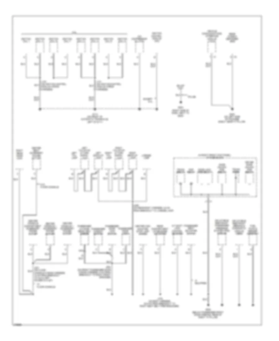
GROUND DISTRIBUTION
Ground Distribution Wiring Diagram (1 of 3) for Chevrolet Impala LS 2008
 https://portal-diagnostov.com/license.html
Automotive Electricians Portal FZCO
Automotive Electricians Portal FZCO
https://portal-diagnostov.com/license.html
https://portal-diagnostov.com/license.html
Automotive Electricians Portal FZCO
Automotive Electricians Portal FZCOList of elements for Ground Distribution Wiring Diagram (1 of 3) for Chevrolet Impala LS 2008:
- (mounted to right strut tower) underhood fuse block
- 5.3l
- Ambient light sensor
- Automatic transaxle
- Auxiliary reading lamp
- B x1
- Base
- Battery
- Body control module (bcm)
- Brake fluid level switch
- Breakout to window switch)
- C2 x1
- California, sulev
- Data link connector (dlc)
- Dome/ reading lamps
- Driver door lock
- Driver door lock switch
- Driver outside rear view mirror
- Driver seat adjuster switch
- Driver window switch
- Engine control module (ecm)
- Engine oil level switch
- Except 5.3l
- Fuel/ pump relay
- G102 (near battery)
- G111 (except 5.3l: on transmission to engine bolt, above starter) (5.3l: on transmission to engine bolt, below starter)
- G202 (on right side of steering column below x201)
- G301 (below driver door opening, rear of left "a" pillar)
- Garage door opener
- Headlamp switch
- Heated seat control module
- Hvac control module
- If equipped
- Ign main pcb relay
- Inside rear view mirror
- Instrument panel cluster (ipc)
- J390 (on roof wiring harness, 53 cm from breakout to dome lamp)
- Left rear door lock
- Left vanity mirror lamp
- Mass air flow (maf)/ intake air temperature (iat) sensor
- Nca
- Outside rear view mirror switch
- Police
- Radio
- Remote control door lock receiver (rcdlr)
- Right vanity mirror lamp
- Secondary air injection (air) solenoid
- Steering angle sensor
- Strtr relay
- Sunroof motor
- Theft deterrent module (tdm)
- Transmission control module (tcm)
- Transmission internal mode switch (ims)
- Turn signal/ multi-function switch
- Turn signal/multifunction switch)
- Uplevel
- W/ front heated seats
- W/ onstar
- W/o onstar
- X100
- Yaw & lateral accelerometer sensor
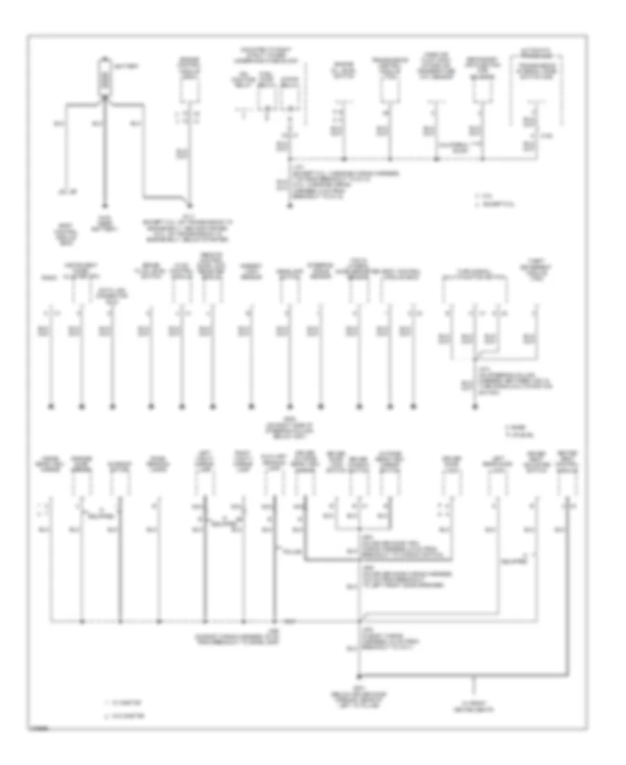
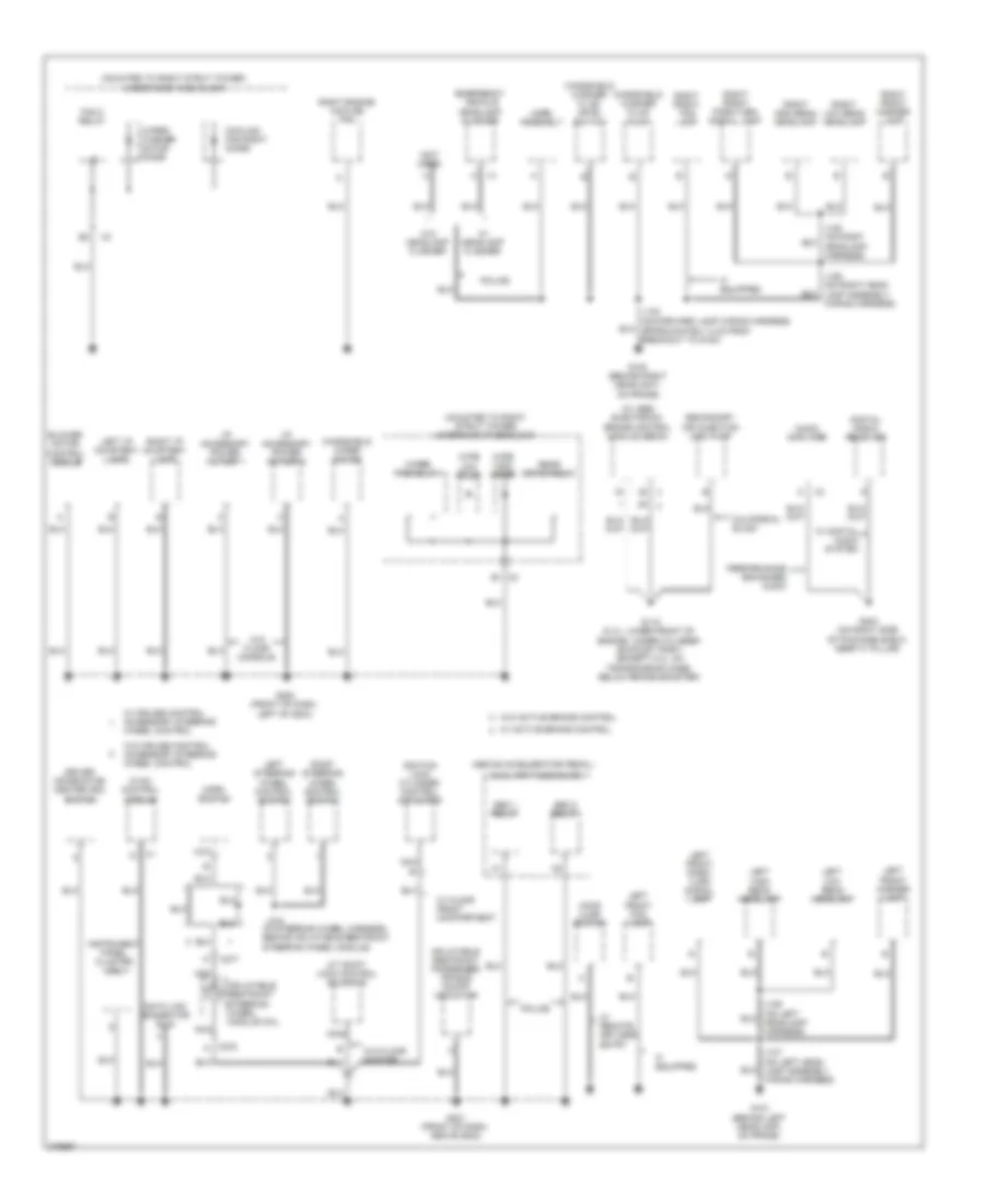
Ground Distribution Wiring Diagram (2 of 3) for Chevrolet Impala LS 2008
 https://portal-diagnostov.com/license.html
Automotive Electricians Portal FZCO
Automotive Electricians Portal FZCO
https://portal-diagnostov.com/license.html
https://portal-diagnostov.com/license.html
Automotive Electricians Portal FZCO
Automotive Electricians Portal FZCOList of elements for Ground Distribution Wiring Diagram (2 of 3) for Chevrolet Impala LS 2008:
- (in right front kick panel) i/p fuse block
- (right side of dash, next to g200)
- 5.3l
- A/c compressor clutch
- A/t shift lock control solenoid
- Center console 1 accessory power outlet
- Center console compartment accessory power outlet
- Center high mounted stop lamp (chmsl)
- Center seat accessory power outlet
- Door lock pcb relay
- Door unlock pcb relay
- Driver door unlock pcb relay
- Except 5.3l
- Fuel pump & sender assembly
- G113 (on front of automatic transaxle, left of g111)
- G204
- G302 (below passenger front door opening, rear of right "a" pillar)
- G403 (on left side of package shelf, near "c" pillar)
- If equipped
- Ignition coil 1
- Ignition coil 2
- Ignition coil 3
- Ignition coil 4
- Ignition coil 5
- Ignition coil 6
- Ignition coil 7
- Ignition coil 8
- Ignition control module (icm)
- Inflatable restraint passenger presence system (pps) module
- Inflatable restraint sensing & diagnostic module (sdm)
- J130 (on ignition control module wiring harness)
- J131 (on ignition control module wiring harness)
- J375 (on body harness, 30.5 cm from breakout to right seat belt pretensioner)
- J485 (on rear body harness, 24 cm from breakout to license lamp)
- J604 (on front passenger door wiring harness, 6 cm from breakout to right front speaker)
- Left back-up lamp
- Left tail lamp
- Left tail/stop & turn signal lamp
- License lamp
- Nca
- Passenger door lock
- Passenger door lock switch
- Passenger outside rear view mirror
- Passenger seat adjuster switch
- Passenger window switch
- Police
- Rap relay
- Rear compartment lid release actuator
- Rear window defogger grid
- Right back-up lamp
- Right rear door lock
- Right tail lamp
- Right tail/stop & turn signal lamp
- Trunk diode
- Trunk relay
- Vehicle communications interface module (vcim)
- W/ floor console
- W/o floor console
- X1 j1
Ground Distribution Wiring Diagram (3 of 3) for Chevrolet Impala LS 2008
 https://portal-diagnostov.com/license.html
Automotive Electricians Portal FZCO
Automotive Electricians Portal FZCO
https://portal-diagnostov.com/license.html
https://portal-diagnostov.com/license.html
Automotive Electricians Portal FZCO
Automotive Electricians Portal FZCOList of elements for Ground Distribution Wiring Diagram (3 of 3) for Chevrolet Impala LS 2008:
- (above accelerator pedal)
- (in steering wheel harness, behind inflatable restraint steering wheel module)
- (mounted to right strut tower) underhood fuse block
- (not used)
- (on forward lamp wiring harness,
- (w/ abs) electronic brake control module (ebcm)
- A/t shift lock control solenoid
- Audio amplifier
- Auxiliary fuse block
- B1 x2
- Blower motor control module
- California, sulev
- Cooling fan right diode
- Data link connector (dlc)
- Digital radio receiver
- Driver information center (dic) switch
- Emergency vehicle headlamp flasher
- Fan 2 relay
- G100 (behind right headlight, on frame)
- G101 (behind left headlamp, on frame)
- G115 (5.3l: lower front of engine, under cylinder exhaust port) (except 5.3l: on transmission case, below brake booster)
- G200 (front of dash, left of g204)
- G201 (front of dash, above g202)
- G404 (on right side of package shelf, near "c" pillar)
- Hood ajar switch
- Horn assembly
- Horn switch
- Hvac control module
- I/p accessory power outlet 1
- I/p accessory power outlet 2
- If equipped
- Ignition lock cylinder control actuator
- Inflatable restraint passenger air bag on/off indicator
- Inflatable restraint steering wheel module coil
- Instrument panel cluster (ipc)
- J124
- J126 (on right head lamp assembly wiring harness)
- J127 (on left head lamp assembly wiring harness)
- J215
- Left front fog lamp
- Left front marker lamp
- Left front park/ turn signal lamp
- Left high beam headlamp
- Left i/p courtesy lamp
- Left low beam headlamp
- Left steering wheel control switch
- Nca
- Performance enhanced audio
- Police
- Rear defog relay
- Right engine cooling fan
- Right front fog lamp
- Right front marker lamp
- Right front park/turn signal lamp
- Right high beam headlamp
- Right i/p courtesy lamp
- Right low beam headlamp
- Right steering wheel control switch
- Secondary air injection (air) pump
- Seo 1 relay
- Seo 2 relay
- W/ active brake control
- W/ cruise control accessory steering wheel control
- W/ digital audio system
- W/ floor front compartment
- W/ headlamp flasher
- W/ remote, keyless entry
- W/o active brake control
- W/o cruise control accessory steering wheel control
- W/o floor console
- W/o floor shifter
- W/o headlamp flasher
- Windshield washer fluid level switch
- Windshield washer fluid pump
- Windshield wiper motor
- Wipe high diode
- Wipe low diode
- Wiper pcb relay
- Wiper/ washer motor diode
- X275 a
- X277
HEADLIGHTS
Headlights Wiring Diagram, with Police Option for Chevrolet Impala LS 2008
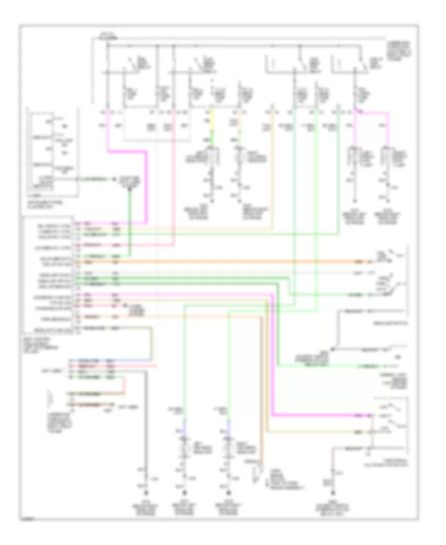 https://portal-diagnostov.com/license.html
Automotive Electricians Portal FZCO
Automotive Electricians Portal FZCO
https://portal-diagnostov.com/license.html
https://portal-diagnostov.com/license.html
Automotive Electricians Portal FZCO
Automotive Electricians Portal FZCOList of elements for Headlights Wiring Diagram, with Police Option for Chevrolet Impala LS 2008:
- (not used)
- Amb lmp sens sig
- Ambient light sensor (top center of dash)
- Auto
- Body control module (bcm) (left of steering column)
- Computer data lines system
- Dimmer sw hi bm sig
- Drl 1 fuse 15a
- Drl 2 fuse 15a
- Drl pcb relay
- Drl pcb rly ctrl
- Fog lamp ind
- Fog lamp switch
- Fog lamps fuse 15a
- Fog lmp rly ctrl
- Fog lmp sw sig
- Fog lp pcb relay
- Ftp
- Ftp sw sig
- G100 (behind right headlamp, on frame)
- G101 (behind left headlamp, on frame)
- G202 (on right side of steering column below x201)
- Gmlan ser data
- Hdlp mdl fuse 15a
- Head
- Headlamp off sw
- Headlamp on sw
- Headlamp switch
- Hi beam rly ctrl
- High
- High beam ind
- High beam pcb relay
- Hot at all times
- Ign
- Instrument panel cluster (ipc)
- J124
- J128
- J129
- J214
- Left front fog lamp
- Left high beam headlamp
- Left low beam headlamp
- Lo spd gmlan ser data
- Logic
- Low
- Low beam pcb relay
- Low beam rly ctrl
- Lt hi beam fuse 10a
- Lt lo beam fuse 10a
- Off
- Park
- Park brake sw
- Park brake switch (part of park brake assembly)
- Pnk
- Rear lmp flash sig
- Right front fog lamp
- Right high beam headlamp
- Right low beam headlamp
- Rt hi beam fuse 10a
- Rt lo beam fuse 10a
- Ser data
- Turn signal/ multifunction switch
- Underhood fuse block (mounted to right strut tower)
- Windshield sw sig
- Wiper/ washer system
- X297
Headlights Wiring Diagram, without Police Option for Chevrolet Impala LS 2008
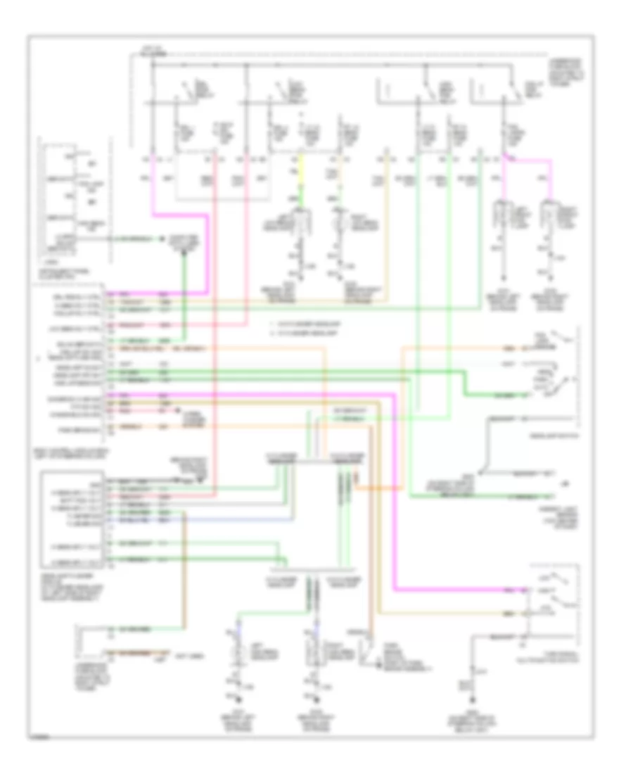 https://portal-diagnostov.com/license.html
Automotive Electricians Portal FZCO
Automotive Electricians Portal FZCO
https://portal-diagnostov.com/license.html
https://portal-diagnostov.com/license.html
Automotive Electricians Portal FZCO
Automotive Electricians Portal FZCOList of elements for Headlights Wiring Diagram, without Police Option for Chevrolet Impala LS 2008:
- (behind right headlamp, on frame) g100
- (not used)
- (or 6841)
- Amb lmp sens sig
- Ambient light sensor (top center of dash)
- Auto
- Batt pos volt
- Body control module (bcm) (left of steering column)
- Computer data lines system
- Dimmer sw hi bm sig
- Drl 1 fuse 15a
- Drl 2 fuse 15a
- Drl pcb relay
- Drl pcb rly ctrl
- Flasher sig
- Fog lamp ind
- Fog lamp switch
- Fog lamps fuse 15a
- Fog lmp rly ctrl
- Fog lmp sw sig rear lmp flash sig
- Fog lp pcb relay
- Ftp
- Ftp sw sig
- G100 (behind right headlamp, on frame)
- G101 (behind left headlamp, on frame)
- G202 (on right side of steering column below x201)
- Gmlan ser data
- Gnd
- Hdlp mdl fuse 15a
- Head
- Headlamp flasher module (w/ flasher headlamp) (at left side of right headlamp assembly)
- Headlamp off sw
- Headlamp on sw
- Headlamp switch
- Hi beam rly ctrl
- Hi beam sply volt
- High
- High beam ind
- High beam pcb relay
- Hot at all times
- Ign
- Instrument panel cluster (ipc)
- J124
- J128
- J129
- J214
- Left front fog lamp
- Left high beam headlamp
- Left low beam headlamp
- Lo spd gmlan ser data
- Logic
- Low
- Low beam pcb relay
- Low beam rly ctrl
- Lt hi beam fuse 10a
- Lt lo beam fuse 10a
- Off
- Park
- Park brake sw
- Park brake switch (part of park brake assembly)
- Pnk
- Right front fog lamp
- Right high beam headlamp
- Right low beam headlamp
- Rt hi beam fuse 10a
- Rt lo beam fuse 10a
- Ser data
- Turn signal/ multifunction switch
- Underhood fuse block (mounted to right strut tower)
- W/ flasher headlamp
- W/o flasher headlamp
- Windshield sw sig
- Wiper/ washer system
- X297
HORN
Horn Wiring Diagram for Chevrolet Impala LS 2008
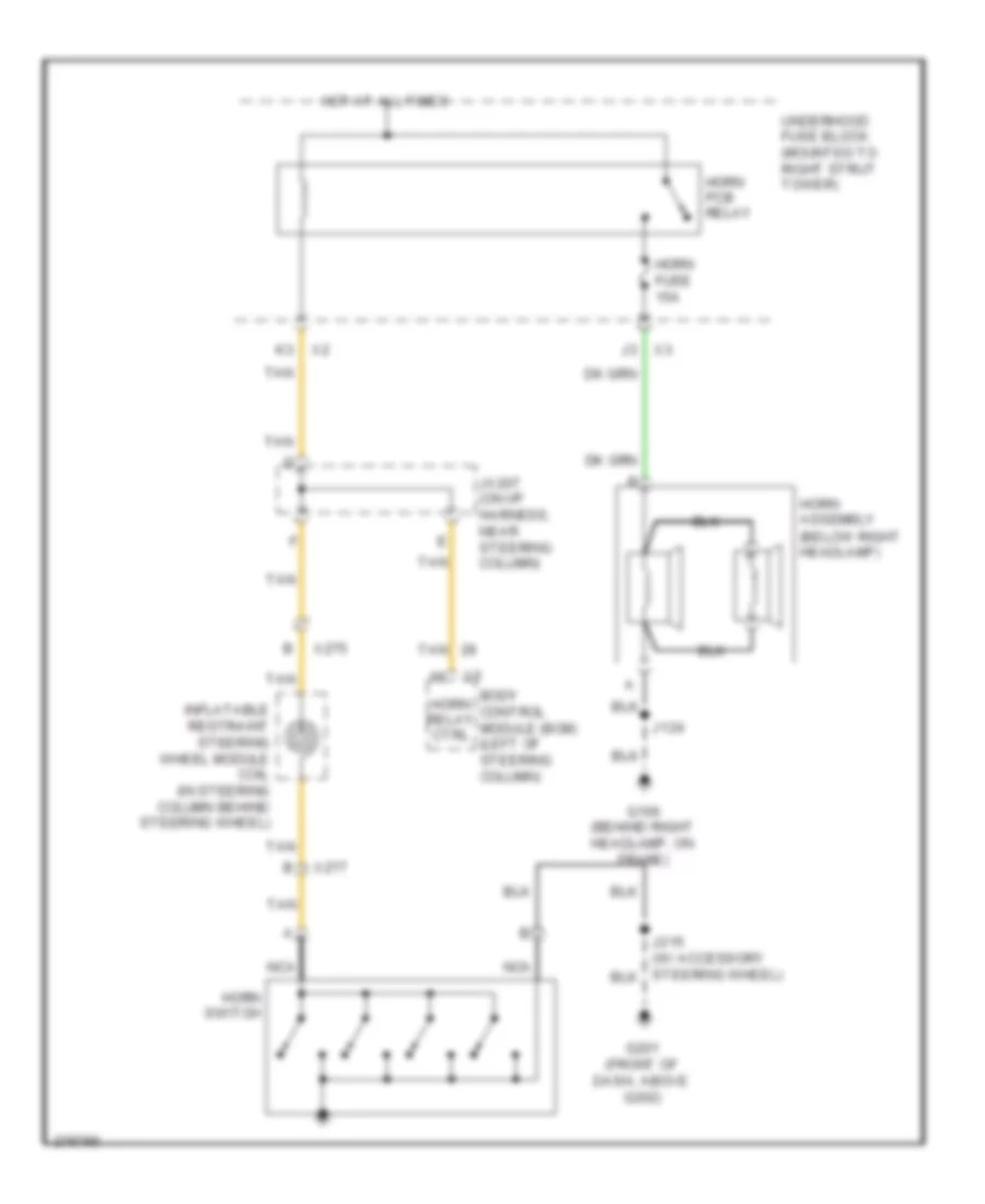 https://portal-diagnostov.com/license.html
Automotive Electricians Portal FZCO
Automotive Electricians Portal FZCO
https://portal-diagnostov.com/license.html
https://portal-diagnostov.com/license.html
Automotive Electricians Portal FZCO
Automotive Electricians Portal FZCOList of elements for Horn Wiring Diagram for Chevrolet Impala LS 2008:
- Body control module (bcm) (left of steering column)
- G100 (behind right headlamp, on frame)
- G201 (front of dash, above g202)
- Horn assembly (below right headlamp)
- Horn fuse 15a
- Horn pcb relay
- Horn relay ctrl
- Horn switch
- Hot at all times
- Inflatable restraint steering wheel module coil (in steering column behind steering wheel)
- J124
- J215 (w/ accessory steering wheel)
- Jx207 (on i/p harness, near steering column)
- Nca
- Tan
- Underhood fuse block (mounted to right strut tower)
- X275
- X277
INSTRUMENT CLUSTER
Instrument Cluster Wiring Diagram for Chevrolet Impala LS 2008
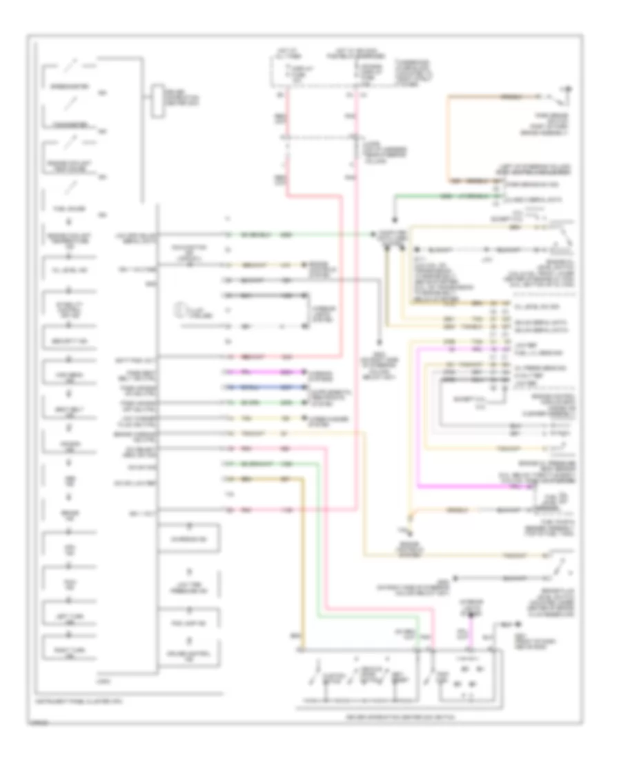 https://portal-diagnostov.com/license.html
Automotive Electricians Portal FZCO
Automotive Electricians Portal FZCO
https://portal-diagnostov.com/license.html
https://portal-diagnostov.com/license.html
Automotive Electricians Portal FZCO
Automotive Electricians Portal FZCOList of elements for Instrument Cluster Wiring Diagram for Chevrolet Impala LS 2008:
- (left of steering column) body control module (bcm)
- 5-volt ref
- 5.3l
- Abs ind
- Air bag ind
- Air bag/ display fuse 10a
- Batt pos volt
- Brake fluid level switch (mounted under center of brake fluid reservoir)
- Brake ind
- Brake warning ind ctrl
- Charging ind
- Class 2 serial data
- Computer data lines system
- Cruise control ind
- Customi- zation
- Dic select menu sw sig
- Dic sw low ref
- Dic sw sig
- Display fuse 10a
- Driver information center (dic)
- Driver information center (dic) switch
- Engine control module (ecm) (inside air cleaner assembly)
- Engine controls system
- Engine coolant temp gauge
- Engine coolant temperature ind
- Engine oil level switch (3.5l & 3.9l: front lower center of engine oil pan) (5.3l: bottom of oil pan)
- Engine oil pressure (eop) sensor (5.3l: below throttle body) (3.5l/3.9l: right of starter)
- Except 5.3l
- Fog lamp ind
- Fuel gauge
- Fuel level sensor
- Fuel lvl sens sig
- Fuel pump & sender assembly (top of fuel tank)
- G111 (3.5l/3.9l: on transmission to engine bolt, above starter) (5.3l: on transmission to engine bolt, below starter)
- G201 (front of dash, above g202)
- G202 (on right side of steering column below x201)
- Gmlan serial data+
- Gmlan serial data-
- Gnd
- High beam ind
- Hot at all times
- Hot w/ ign main pcb relay energized
- Ign
- Ign 1 volt
- Ign 1 voltage
- Illum (4 bulbs)
- Instrument panel cluster (ipc)
- Interior lights system
- J101
- Jx206 (on i/p harness, near steering column)
- Km/h ind
- Left turn ind
- Logic
- Low ref
- Low spd gmlan serial data
- Low tire pressure ind
- Low washer fluid ind ctrl
- Malfunction ind lamp (mil)
- Mph ind
- Oil level ind
- Oil level sw sig
- Oil press sens sig
- Park brake sw sig
- Park brake switch (part of park brake assembly)
- Pass air bag off ind ctrl
- Pass air bag on ind ctrl
- Pass seat belt ind ctrl
- Pnk
- Right turn ind
- Seat belt ind
- Security ind
- Set/ reset
- Speedometer
- Stability control off ind
- Tachometer
- Tan
- Trip/ fuel
- Underhood fuse block (mounted to right strut tower)
- Vehicle infor- mation
- Warning systems
- Wiper/washer system
INTERIOR LIGHTS
Courtesy Lamps Wiring Diagram for Chevrolet Impala LS 2008
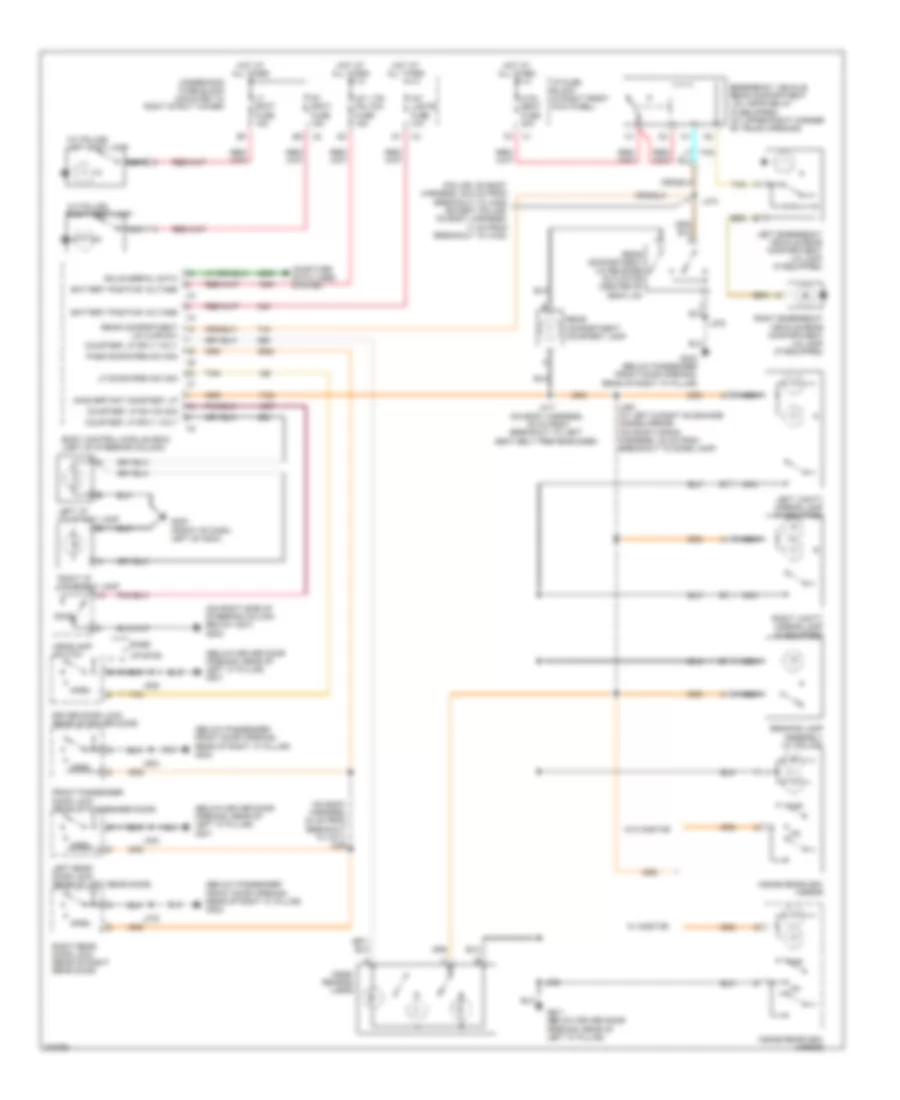 https://portal-diagnostov.com/license.html
Automotive Electricians Portal FZCO
Automotive Electricians Portal FZCO
https://portal-diagnostov.com/license.html
https://portal-diagnostov.com/license.html
Automotive Electricians Portal FZCO
Automotive Electricians Portal FZCOList of elements for Courtesy Lamps Wiring Diagram for Chevrolet Impala LS 2008:
- (below driver door opening, rear of left "a" pillar) g301
- (below passenger front door opening, rear of right "a" pillar) g302
- (on body harness, 24 cm from breakout to x311) j359
- (on right side of steering column below x201) g202
- (police: on body harness, 45.5 cm from breakout to x409) (except police: on body harness, 17 cm from breakout to x430)
- (w/ police) left spot lamp
- (w/ police) right spot lamp
- Base
- Battery positive voltage
- Body control module (bcm) (left of steering column)
- Computer data lines system
- Courtesy lp sply volt
- Courtesy lp sw on sig
- Dome
- Dome/ reading lamps
- Driver door lock (rear of driver door)
- Emergency vehicle rear compartment lid lamps relay (if equipped) (at upper right corner of trunk opening)
- Front passenger door lock (rear of passenger door)
- G200 (front of dash, left of g204)
- G301 (below driver door opening, rear of left "a" pillar)
- G302 (below passenger front door opening, rear of right "a" pillar)
- Gmlan serial data
- Headlamp switch
- Hot at all times
- Htd/ seat fuse 20a
- I/p fuse block (in right front kick panel)
- Inadvertant courtesy lp
- Inside rearview mirror
- Int lights fuse 10a
- Int lts/ pnl dim fuse 15a
- J303
- J375
- J376
- J390
- J393 (w/ left & right sunshade inside mirror) (on roof wiring harness, 38 cm from breakout to dome lamp)
- J417 (on body harness, 32 cm from breakout to left seat belt pretensioner)
- J474
- J505
- J604
- Left emergency vehicle rear compartment lid lamp (if equipped)
- Left i/p courtesy lamp
- Left rear door lock (rear of left rear door)
- Left vanity mirror lamp (if equipped)
- Lf door open sw sig
- Lid ajar sw
- Lt spot fuse 15a
- Nca
- Off
- Open
- Pass door open sw sig
- Reading lamp assembly (w/ police)
- Rear compartment
- Rear compartment courtesy lamp
- Rear compartment lid release actuator (center of deck lid)
- Right emergency vehicle rear compartment lid lamp (if equipped)
- Right i/p courtesy lamp
- Right rear door lock (rear of right rear door)
- Right vanity mirror lamp (if equipped)
- Rt spot fuse 15a
- Tan
- Underhood fuse block (mounted to right strut tower)
- Uplevel
- W/ onstar
- W/o onstar
Instrument Illumination Wiring Diagram for Chevrolet Impala LS 2008
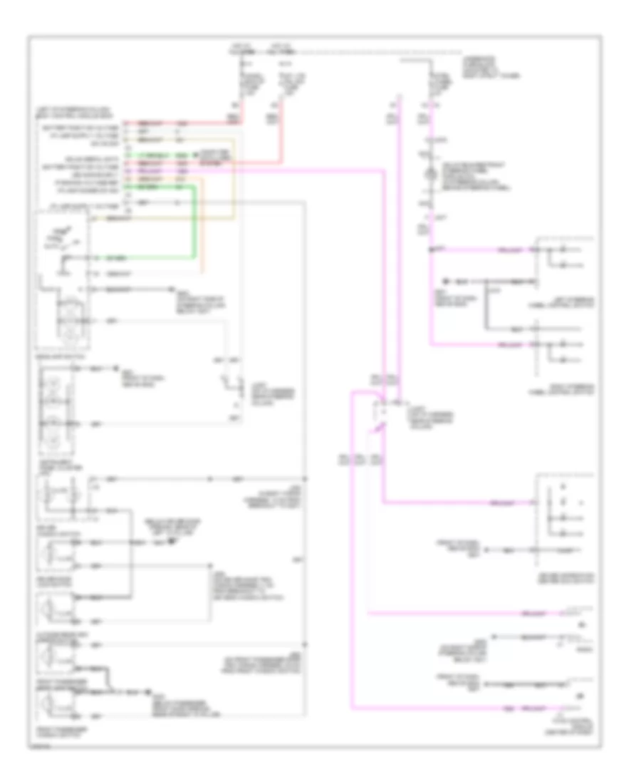 https://portal-diagnostov.com/license.html
Automotive Electricians Portal FZCO
Automotive Electricians Portal FZCO
https://portal-diagnostov.com/license.html
https://portal-diagnostov.com/license.html
Automotive Electricians Portal FZCO
Automotive Electricians Portal FZCOList of elements for Instrument Illumination Wiring Diagram for Chevrolet Impala LS 2008:
- (below driver door opening, rear of left "a" pillar) g301
- (front of dash, above g202) g201
- (left of steering column) body control module (bcm)
- Auto
- Battery positive voltage
- Chmsl/ bck-up fuse 10a
- Computer data lines system
- Driver door lock switch
- Driver information center (dic) switch
- Driver window switch
- Front passenger door lock switch
- Front passenger window switch
- G201 (front of dash, above g202)
- G202 (on right side of steering column below x201)
- G302 (below passenger front door opening, rear of right "a" pillar)
- Gmlan serial data
- H4 x4
- Head
- Headlamp switch
- Hot at all times
- Hvac control module (center of dash)
- I/p lamp dimmer sw sig
- Illum
- Inflatable restraint steering wheel module coil (in steering column behind steering wheel)
- Instrument panel cluster (ipc)
- Int lts/ pnl dim fuse 15a
- Ip dimming voltage ref
- J215
- J277
- J308 (in body wiring harness, 14 cm from breakout to g301)
- J504
- J506 (on driver door trim wiring harness,11 cm from breakout to driver's window switch)
- J608 (on front passenger door trim wiring harness, 6.5 cm from front window switch)
- Jx207 (on i/p harness, near steering column)
- Led dimming sply
- Left steering wheel control switch
- Nca
- Off
- Outside rearview mirror switch
- Park
- Radio
- Right steering wheel control switch
- Strg wheel fuse 2a
- Sw on sig
- Underhood fuse block (mounted to right strut tower)
- X275
- X277
POWER DISTRIBUTION
Power Distribution Wiring Diagram (1 of 4) for Chevrolet Impala LS 2008
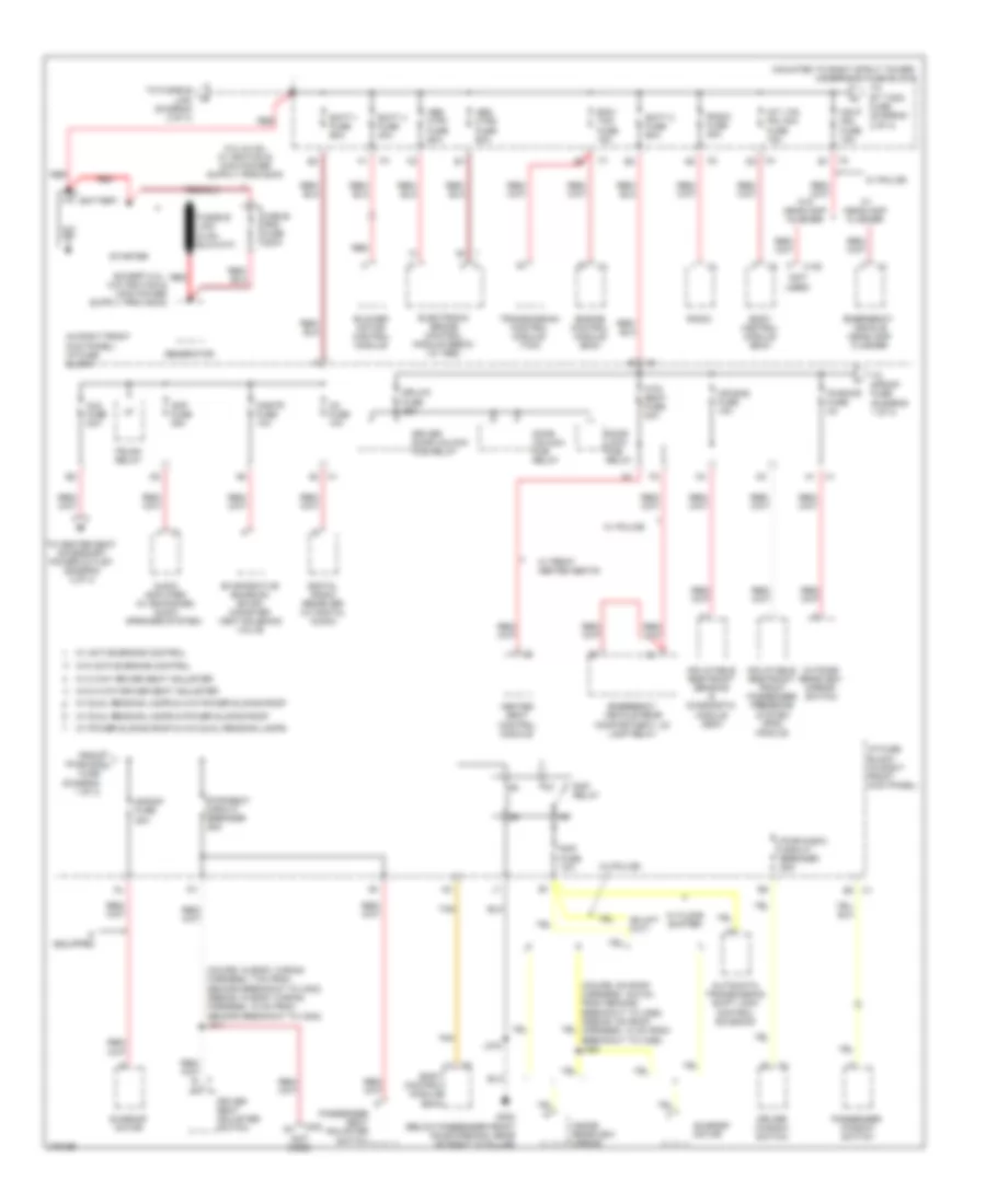 https://portal-diagnostov.com/license.html
Automotive Electricians Portal FZCO
Automotive Electricians Portal FZCO
https://portal-diagnostov.com/license.html
https://portal-diagnostov.com/license.html
Automotive Electricians Portal FZCO
Automotive Electricians Portal FZCOList of elements for Power Distribution Wiring Diagram (1 of 4) for Chevrolet Impala LS 2008:
- (coupe: in body wiring harness, 7 cm from second breakout to x302) (sedan: in body wiring harness, 10 cm from second breakout to x302) j311
- (in right front kick panel) i/p fuse block
- (mounted to right strut tower) underhood fuse block
- (not used)
- Abs mtr1 fuse 60a
- Abs mtr2 fuse 60a
- Air bag fuse 10a
- Amp fuse 25a
- Audio amplifier (w/ enhanced audio speaker system)
- Automatic transmission shift lock control solenoid
- Aux fuse 20a
- B3 x1
- Batt 1 fuse 60a
- Batt 2 fuse 60a
- Batt 4 fuse 30a
- Battery
- Blower motor control module
- Body control module (bcm)
- Cable pro fuse 200a
- Cnstr fuse 10a
- Digital radio receiver (w/ digital audio)
- Door lock pcb relay
- Door unlock pcb relay
- Dr/lck fuse 25a
- Driver door unlock pcb relay
- Driver seat adjuster switch
- Driver window switch
- Ecm/ tcm fuse 15a
- Electronic brake control module (ebcm) (w/ abs)
- Emergency vehicle headlamp flasher
- Emergency vehicle rear compartment lid lamp relay
- Engine control module (ecm)
- Evaporative emission (evap) canister vent solenoid valve
- From pwr/mir j fuse (diagram 1 of 4)
- G302 (below passenger front door opening, rear of right "a" pillar)
- Generator
- Hdlp mdl fuse 15a
- Heated seat control module
- Htd/ seat fuse 20a
- I/p fuse block (in right front kick panel)
- If equipped
- Inflatable restraint front passenger presence system (pps) module
- Inflatable restraint sensing & diagnostic module (sdm)
- Inside rearview mirror
- Int lts/ pnl dim fuse 15a
- J375
- Outside rearview mirror switch
- Passenger seat adjuster switch
- Passenger window switch
- Pwr/mir fuse 2a
- Pwr/seat circuit breaker 25a
- Pwr/wndw circuit breaker 25a
- Radio
- Radio fuse 20a
- Rap fuse 10a
- Rap relay
- Red
- S/roof fuse 20a
- Starter
- Sunroof motor
- Tan
- To center seat accessory power outlet (diagram 2 0f 4)
- To fusible link (diagram 2 of 4)
- To rt t/sig fuse (diagram 2 of 4)
- To s/roof fuse (diagram 1 of 4)
- Transmission control module (tcm)
- Trunk relay
- W/ 8 way driver seat adjuster
- W/ active brake control
- W/ dual reading lamps & power sliding roof
- W/ dual reading lamps & w/o power sliding roof
- W/ floor shifter
- W/ front heated seats
- W/ headlamp flasher
- W/ police
- W/ power sliding roof & w/o dual reading lamps
- W/o 8 way driver seat adjuster
- W/o active brake control
- W/o headlamp flasher
- X1 c2
- X122
- X3 b1
- X302
- X4 d2
- Xm fuse 10a
Power Distribution Wiring Diagram (2 of 4) for Chevrolet Impala LS 2008
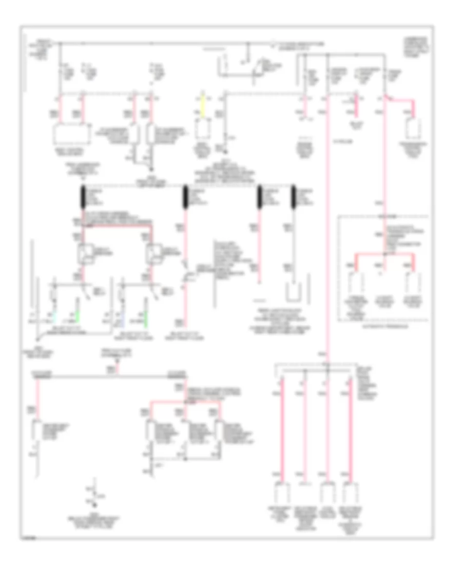 https://portal-diagnostov.com/license.html
Automotive Electricians Portal FZCO
Automotive Electricians Portal FZCO
https://portal-diagnostov.com/license.html
https://portal-diagnostov.com/license.html
Automotive Electricians Portal FZCO
Automotive Electricians Portal FZCOList of elements for Power Distribution Wiring Diagram (2 of 4) for Chevrolet Impala LS 2008:
- (in automatic transaxle wiring harness, 9.5 cm from connector x100) j115
- 1-2 shift solenoid valve
- 2-3 shift solenoid valve
- 30a
- 50a
- Air bag/ display fuse 10a
- Automatic transaxle
- Aux pwr fuse 25a
- Body control module (bcm)
- Center console accessory power outlet 1
- Center console accessory power outlet 2
- Center console compartment accessory power outlet
- Center seat accessory power outlet
- Circuit breaker
- Ecm ign fuse 10a
- Engine control module (ecm)
- From aux fuse (diagram 1 of 4)
- From hdlp mdl a fuse (diagram 1 of 4)
- From underhood fuse block (diagram 1 of 4)
- G111 (except 5.3l on transmission to engine bolt, above starter) (5.3l: on transmission to engine bolt, below starter)
- G200 (front of dash, left of g204)
- G201 (front of dash, above g202)
- G302 (below passenger front door opening, rear of right "a" pillar)
- Hvac control module
- I/p accessory power outlet 1 (w/o floor console)
- I/p accessory power outlet 2 (w/o floor console)
- Ign main pcb relay
- Inflatable restraint passenger air bag on/off indicator
- Inflatable restraint sensing & diagnostic module (sdm)
- Instrument panel cluster (ipc)
- J101
- J231
- J375
- Lt t/sig fuse 15a
- Pnk
- Pwr drop/ crank fuse 10a
- Red
- Rt t/sig fuse 15a
- Seo 1 relay
- Seo 2 relay
- Splice pack sp206 (on i/p harness, near steering column)
- To chmsl/backup fuse (diagram 3 of 4)
- Torque converter clutch (tcc) solenoid valve
- Trans fuse 10a
- Transmission control module (tcm)
- Underhood fuse block (mounted to right strut tower)
- W/ floor console
- W/ police
- W/o floor console
- X1 j3
- X100
- X2 e2
- X4 k1
Power Distribution Wiring Diagram (3 of 4) for Chevrolet Impala LS 2008
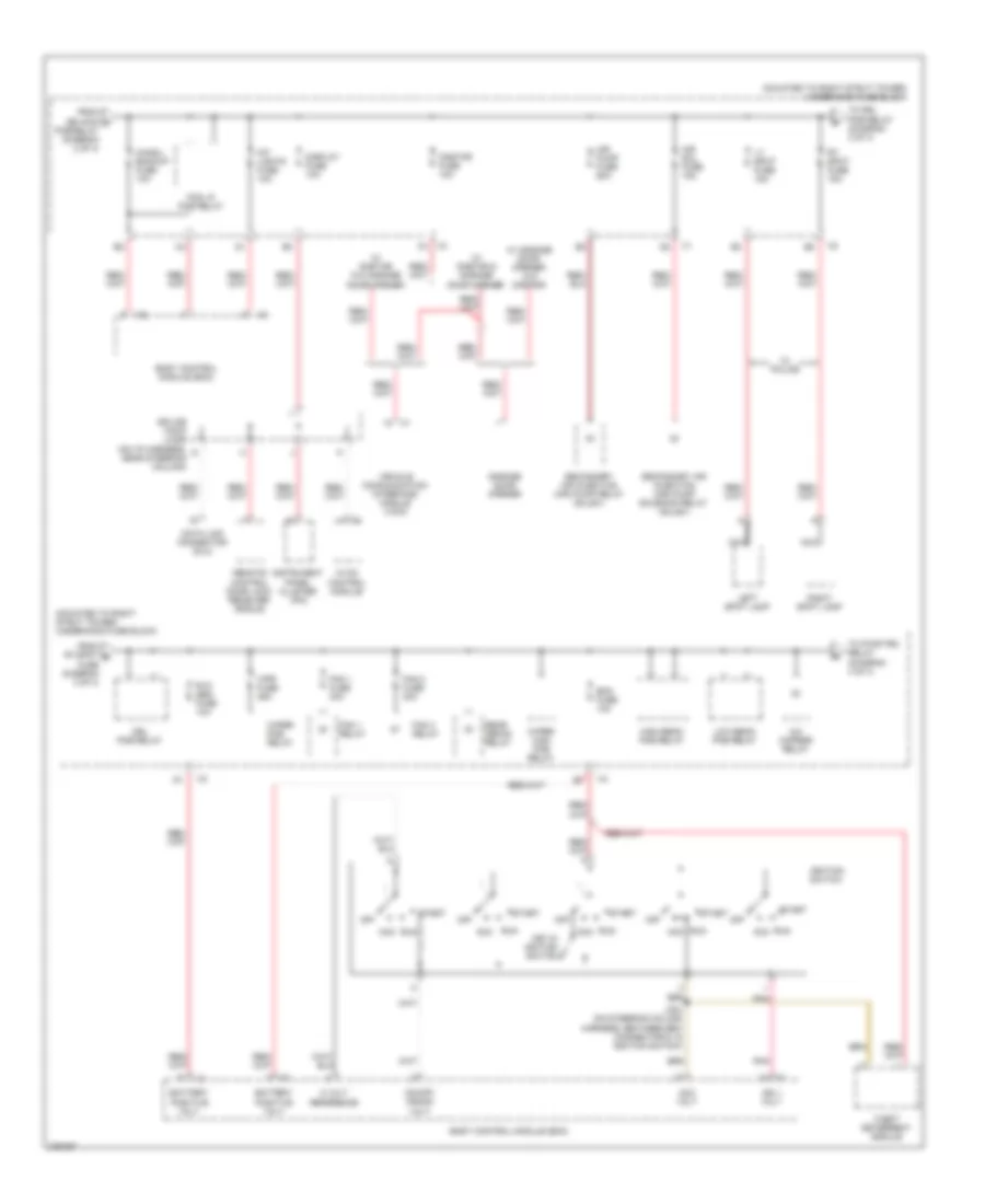 https://portal-diagnostov.com/license.html
Automotive Electricians Portal FZCO
Automotive Electricians Portal FZCO
https://portal-diagnostov.com/license.html
https://portal-diagnostov.com/license.html
Automotive Electricians Portal FZCO
Automotive Electricians Portal FZCOList of elements for Power Distribution Wiring Diagram (3 of 4) for Chevrolet Impala LS 2008:
- (mounted to right strut tower) underhood fuse block
- 5 volt reference
- A/c cmprsr relay
- Acc
- Acc volt
- Air pump fuse 60a
- Air sol fuse 15a
- Battery positive volt
- Bcm fuse 10a
- Body control module (bcm)
- Chmsl/ backup fuse 10a
- Data link connector (dlc)
- Display fuse 10a
- Drl pcb relay
- Fan 1 fuse 30a
- Fan 1 relay
- Fan 2 fuse 30a
- Fan 3 relay
- Fog lp pcb relay
- From ign main c pcb relay (diagram 2 of 4)
- From rt spot d fuse (diagram 3 of 4)
- Garage door opener
- High beam pcb relay
- Hvac control module
- Ign 1 volt
- Ignition switch
- Instrument panel cluster (ipc)
- Int lights fuse 10a
- J204 (on steering column harness, between bcm connector c1 & ignition switch)
- Key in ignition switch
- Left spot lamp
- Low beam pcb relay
- Lt spot fuse 15a
- Nca
- Off
- On/off/ crank volt
- Onstar fuse 10a
- Pnk
- Rear defog relay
- Remote control door lock receiver (rcdlr)
- Right spot lamp
- Rt spot fuse 15a
- Run
- Rvc sen fuse 10a
- Secondary air injection (air) pump relay (sulev)
- Secondary air injection (air) pump solenoid relay (sulev)
- Splice pack jx206 (on i/p harness, near steering column)
- Start
- Theft deterrent module
- To drl pcb relay (diagram 3 of 4)
- To pwr/trn relay (diagram 4 of 4)
- Vehicle communication interface module (vcim)
- W/ garage door opener w/o onstar
- W/ onstar & garage door opener
- W/ onstar w/o garage door opener
- W/ police
- Wiper high pcb relay
- Wiper pcb relay
- Wpr fuse 25a
- X4 f3
Power Distribution Wiring Diagram (4 of 4) for Chevrolet Impala LS 2008
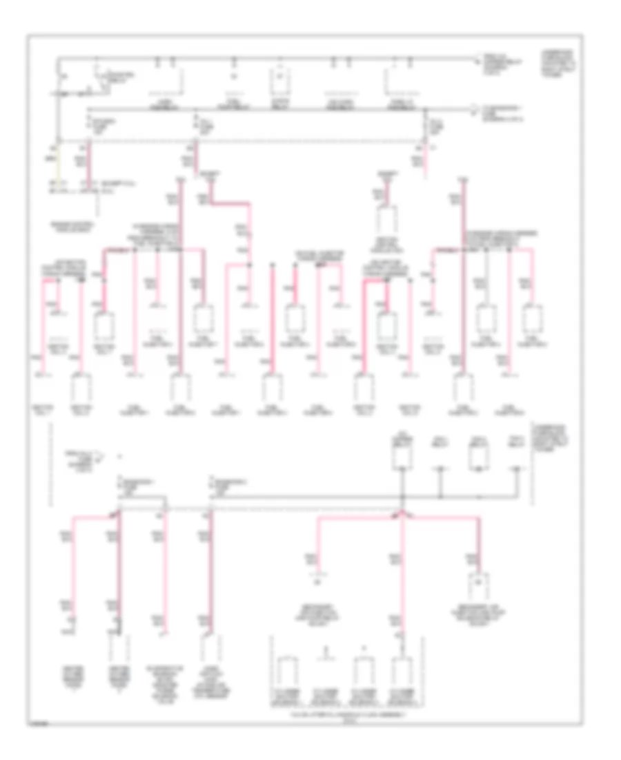 https://portal-diagnostov.com/license.html
Automotive Electricians Portal FZCO
Automotive Electricians Portal FZCO
https://portal-diagnostov.com/license.html
https://portal-diagnostov.com/license.html
Automotive Electricians Portal FZCO
Automotive Electricians Portal FZCOList of elements for Power Distribution Wiring Diagram (4 of 4) for Chevrolet Impala LS 2008:
- (5.3l)
- (except 5.3l)
- (in engine wiring harness, 5 cm from breakout to fuel injector 3) j108
- (in engine wiring harness, 5 cm from breakout to fuel injector 4) j109
- (on fuel injector wiring harness) j109
- (on ignition control module wiring harness) j106
- (on ignition control module wiring harness) j107
- 5.3l
- A/c cmprsr relay
- Cylinder shutoff solenoid 1
- Cylinder shutoff solenoid 2
- Cylinder shutoff solenoid 3
- Cylinder shutoff solenoid 4
- Emissions 1 fuse 15a
- Emissions 2 fuse 15a
- Engine control module (ecm)
- Etc/ecm fuse 15a
- Evaporative emission (evap) canister purge solenoid valve
- Except 5.3l
- Fan 1 relay
- Fan 2 relay
- Fan 3 relay
- From a/c cmprsr relay (diagram 3 of 4)
- From inj 2 fuse g (diagram 4 of 4)
- Fuel injector 1
- Fuel injector 2
- Fuel injector 3
- Fuel injector 4
- Fuel injector 5
- Fuel injector 6
- Fuel injector 7
- Fuel injector 8
- Fuel/ pump relay
- Heated oxygen sensor (ho2s)
- Horn pcb relay
- Ignition coil 1
- Ignition coil 2
- Ignition coil 3
- Ignition coil 4
- Ignition coil 5
- Ignition coil 6
- Ignition coil 7
- Ignition coil 8
- Ignition control module (icm)
- Inj 1 fuse 20a
- Inj 2 fuse 20a
- Mass air flow (maf)/ intake air temperature (iat) sensor
- Nca
- Park lp pcb relay
- Pnk
- Pwr/trn relay
- Secondary air injection (air) pump relay (sulev)
- Secondary air injection (air) pump solenoid relay (sulev)
- Strtr relay
- To emissions 1 fuse (diagram 4 of 4)
- Underhood fuse block (mounted to right strut tower)
- Valve lifter oil manifold (vlom) assembly (5.3l)
- Ws wash pcb relay
POWER DOOR LOCKS
Power Door Locks Wiring Diagram (1 of 2) for Chevrolet Impala LS 2008
 https://portal-diagnostov.com/license.html
Automotive Electricians Portal FZCO
Automotive Electricians Portal FZCO
https://portal-diagnostov.com/license.html
https://portal-diagnostov.com/license.html
Automotive Electricians Portal FZCO
Automotive Electricians Portal FZCOList of elements for Power Door Locks Wiring Diagram (1 of 2) for Chevrolet Impala LS 2008:
- (below driver door opening, rear of left "a" pillar)
- (below passenger front door opening, rear of right "a" pillar) g302
- (top left side of windshield) (if equipped) keyless entry antenna
- (under defroster grill panel) remote control door lock receiver (rcdlr)
- Ajar
- Ajar sw sig
- Antenna sig
- B3 x4
- Body control module (bcm) (left of steering column)
- Closed
- Coax
- Computer data lines system
- Display fuse 10a
- Door lock pcb relay
- Door unlock pcb relay
- Dr/lck fuse 25a
- Driver door lock switch
- Driver door unlock pcb relay
- Exterior lights system
- G101 (behind left headlight, on frame)
- G202 (on right side of steering column below x201)
- G301
- G302 (below passenger front door opening, rear of right "a" pillar)
- G303 (near top of left "a" pillar)
- Ground
- Ground distribution system
- Hazard sw sig
- Headlights system
- Hi beam relay
- Hood ajar sw
- Hood ajar switch (w/ remote keyless entry) (part of hood latch)
- Hood closed sw
- Horn rly ctrl
- Horns system
- Hot at all times
- I/p fuse block (in right front kick panel)
- Interior lights system
- J1 x1
- J375
- J474 (45.5 cm from breakout to x409)
- J504
- J604
- Jx206 (on i/p harness, near steering column)
- Lf open sw sig
- Lid ajar sw sig
- Lock
- Lock rly ctrl
- Lock sig
- Pass dr open sw
- Passenger door lock switch
- Police
- Prk lmp rly ctrl
- Rear compartment lid release actuator (center of deck lid)
- Rf ajar sw sig
- Rvc sen fuse 10a
- Serial data
- Tan
- Trunk relse rly
- Trunk, tailgate, fuel doors system
- Underhood fuse block (mounted to right strut tower)
- Unlock
- Unlock rly ctrl
- Unlock sig
- X2 g1
Power Door Locks Wiring Diagram (2 of 2) for Chevrolet Impala LS 2008
 https://portal-diagnostov.com/license.html
Automotive Electricians Portal FZCO
Automotive Electricians Portal FZCO
https://portal-diagnostov.com/license.html
https://portal-diagnostov.com/license.html
Automotive Electricians Portal FZCO
Automotive Electricians Portal FZCOList of elements for Power Door Locks Wiring Diagram (2 of 2) for Chevrolet Impala LS 2008:
- (below driver door opening, rear of left "a" pillar) g301
- (sedan: 5 cm from breakout to x313) (coupe: 5 cm from breakout to inflatable restraint sensing & diagnostic module) j315
- Air bag/ display fuse 10a
- Ajar
- Base
- Computer data lines system
- Door lock actuator
- Door lock ajar indicator switch
- Door lock open indicator switch
- Driver door lock (rear of driver door)
- Driver information center (dic)
- Front passenger door lock (rear of passenger door)
- G302 (below passenger front door opening, rear of right "a" pillar)
- Hot w/ ign main pcb relay energized
- Ign
- Ign 1 volt
- Instrument panel cluster (ipc)
- J303
- J314 (sedan: 16 cm from breakout to x313)
- J359 (sedan: 24 cm from breakout to x311)
- J375
- J505
- J604
- Jx206 (on i/p harness, near steering column)
- K4 x4
- Left rear door lock (rear of left rear door)
- Logic
- Low speed gmlan serial data
- Open
- Pnk
- Right rear door lock (rear of right rear door)
- Security ind
- Tan
- Underhood fuse block (mounted to right strut tower)
- Uplevel
POWER MIRRORS
Electrochromic Mirror Wiring Diagram, with OnStar for Chevrolet Impala LS 2008
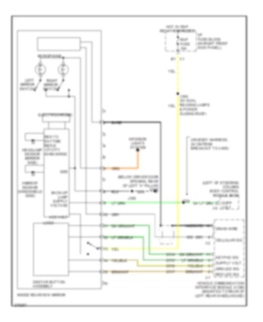 https://portal-diagnostov.com/license.html
Automotive Electricians Portal FZCO
Automotive Electricians Portal FZCO
https://portal-diagnostov.com/license.html
https://portal-diagnostov.com/license.html
Automotive Electricians Portal FZCO
Automotive Electricians Portal FZCOList of elements for Electrochromic Mirror Wiring Diagram, with OnStar for Chevrolet Impala LS 2008:
- & power sliding roof)
- (below driver door opening, rear of left "a" pillar) g301
- (left of steering column) body control module (bcm)
- (on body harness, 24 cm from breakout to x405)
- Acc volt
- Ambient sensor (windshield side)
- B1 x1
- Bare
- Cellular sig
- Drain wire
- Electrochromic
- Gnd
- Headlamp sensor (mirror side)
- Hot w/ rap relay energized
- I/p fuse block (in right front kick panel)
- Inside rearview mirror
- Interior lights system
- J324
- J390
- Keypad sig
- Left mirror switch
- Logic
- Microphone
- Onstar button assembly
- Rap fuse 10a
- Red led sig
- Res to daytime refle -ctivity in reverse
- Right mirror switch
- Supp
- Vehicle communication interface module (vcim) (mounted to rear of left rear wheelhouse)
- Volt x6
Electrochromic Mirror Wiring Diagram, without OnStar for Chevrolet Impala LS 2008
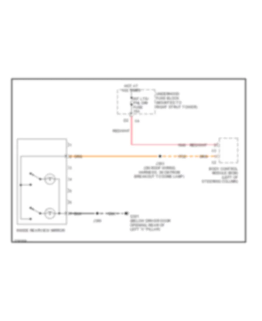 https://portal-diagnostov.com/license.html
Automotive Electricians Portal FZCO
Automotive Electricians Portal FZCO
https://portal-diagnostov.com/license.html
https://portal-diagnostov.com/license.html
Automotive Electricians Portal FZCO
Automotive Electricians Portal FZCOList of elements for Electrochromic Mirror Wiring Diagram, without OnStar for Chevrolet Impala LS 2008:
- Body control module (bcm) (left of steering column)
- G301 (below driver door opening, rear of left "a" pillar)
- Hot at all times
- Inside rearview mirror
- Int lts/ pnl dim fuse 15a
- J390
- J393 (on roof wiring harness, 38 cm from breakout to dome lamp)
- Underhood fuse block (mounted to right strut tower)
Power Mirrors Wiring Diagram for Chevrolet Impala LS 2008
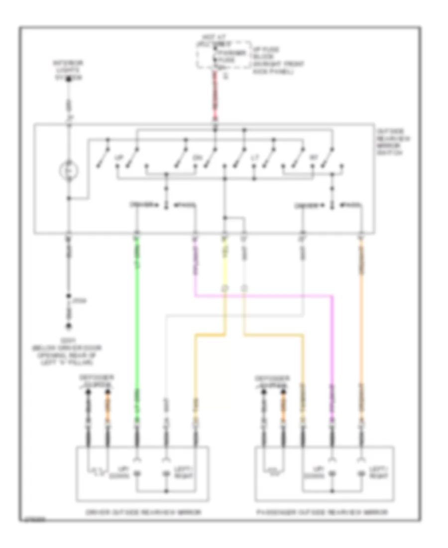 https://portal-diagnostov.com/license.html
Automotive Electricians Portal FZCO
Automotive Electricians Portal FZCO
https://portal-diagnostov.com/license.html
https://portal-diagnostov.com/license.html
Automotive Electricians Portal FZCO
Automotive Electricians Portal FZCOList of elements for Power Mirrors Wiring Diagram for Chevrolet Impala LS 2008:
- Defogger system
- Driver
- Driver outside rearview mirror
- G301 (below driver door opening, rear of left "a" pillar)
- Hot at all times
- I/p fuse block (in right front kick panel)
- Interior lights system
- J504
- Left/ right
- Nca
- Outside rearview mirror switch
- Pass
- Passenger outside rearview mirror
- Pwr/mir fuse 2a
- Tan
- Up/ down
POWER SEATS
Heated Seats Wiring Diagram for Chevrolet Impala LS 2008
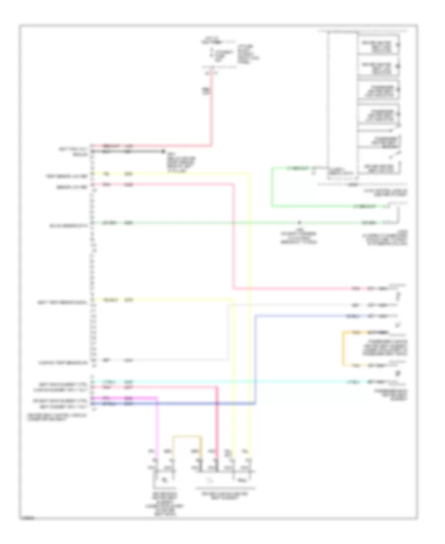 https://portal-diagnostov.com/license.html
Automotive Electricians Portal FZCO
Automotive Electricians Portal FZCO
https://portal-diagnostov.com/license.html
https://portal-diagnostov.com/license.html
Automotive Electricians Portal FZCO
Automotive Electricians Portal FZCOList of elements for Heated Seats Wiring Diagram for Chevrolet Impala LS 2008:
- Batt pos volt
- Class 2 serial data
- Cushion element sply volt
- Cushion temp sensor sig
- Dr seat back element ctrl
- Driver back heated seat element (under upholstery of driver seat back)
- Driver cushion heated seat element
- Driver heated seat high indicator
- Driver heated seat low indicator
- Driver heated seat switch
- G301 (below driver door opening, rear of left "a" pillar)
- Gmlan sensor data
- Ground
- Heated seat control module (under driver seat)
- Hot at all times
- Htd/seat fuse 20a
- Hvac control module (center of dash)
- I/p fuse block (in right front kick panel)
- J350 (on body harness, 14.5 cm from breakout to g302)
- Jx205 (clipped to inner dash structure, to right of steering column)
- Logic
- Nca
- Passenger back heated seat element
- Passenger cushion heated seat element (under upholstery of passenger seat back)
- Passenger heated seat high indicator
- Passenger heated seat low indicator
- Passenger heated seat switch
- Pnk
- Seat back element ctrl
- Seat element sply volt
- Seat temp sensor signal
- Sensor low ref
- Tan
- Temp sensor low ref
- X1 g1
Power Seat Wiring Diagram for Chevrolet Impala LS 2008
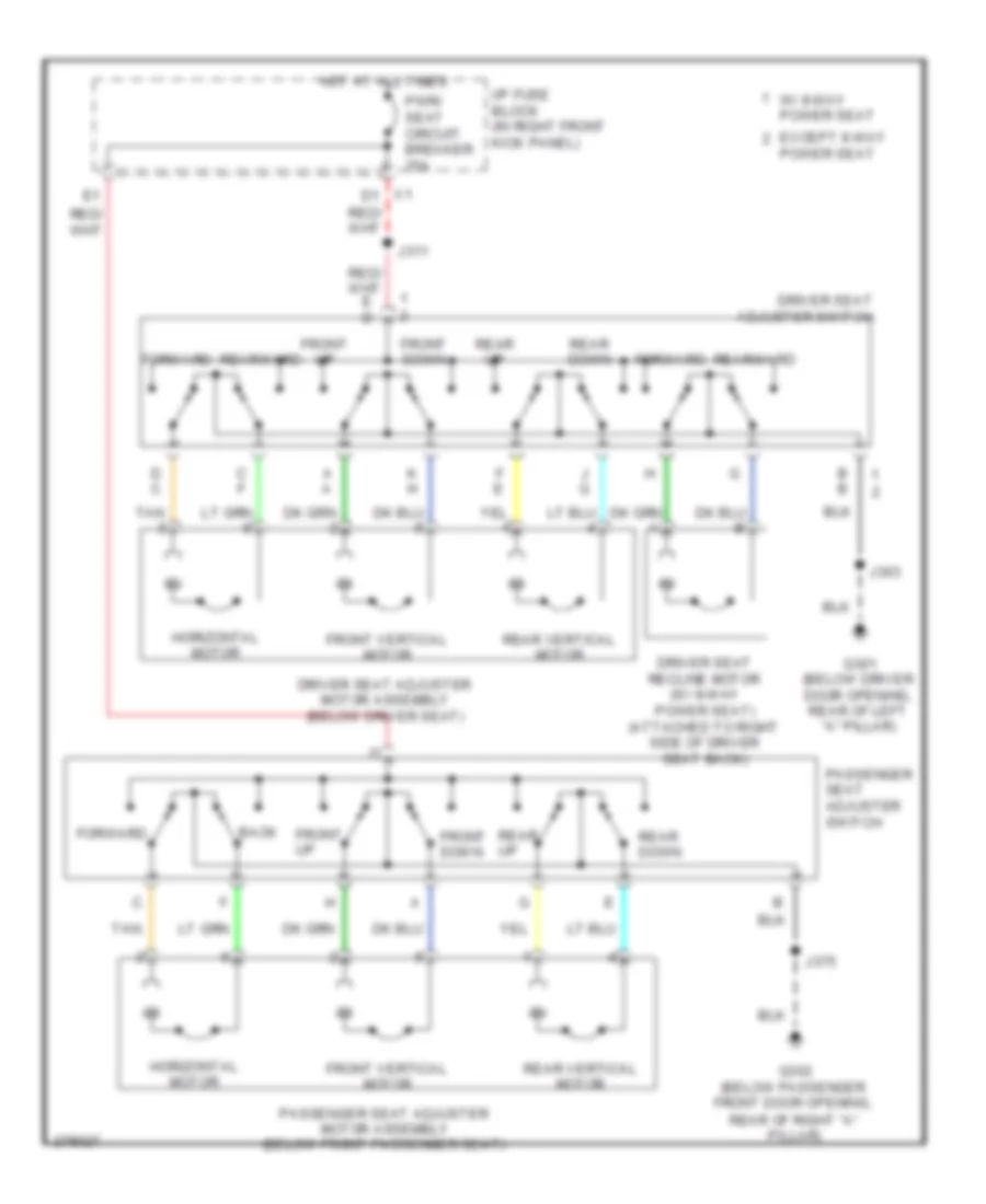 https://portal-diagnostov.com/license.html
Automotive Electricians Portal FZCO
Automotive Electricians Portal FZCO
https://portal-diagnostov.com/license.html
https://portal-diagnostov.com/license.html
Automotive Electricians Portal FZCO
Automotive Electricians Portal FZCOList of elements for Power Seat Wiring Diagram for Chevrolet Impala LS 2008:
- A a
- B b
- Back
- C f
- D c
- Driver seat adjuster motor assembly (below driver seat)
- Driver seat adjuster switch
- Driver seat recline motor (w/ 8-way power seat) (attached to right side of driver seat back)
- Except 8-way
- F e
- Forward
- Front down
- Front up
- Front vertical motor
- G301 (below driver door opening, rear of left "a" pillar)
- G302 (below passenger front door opening,
- Horizontal motor
- Hot at all times
- I/p fuse block (in right front kick panel)
- J g
- J303
- J311
- J375
- K h
- Passenger seat adjuster motor assembly (below front passenger seat)
- Passenger seat adjuster switch
- Power seat
- Pwr/ seat circuit breaker 25a
- Rear down
- Rear of right "a" pillar)
- Rear up
- Rear vertical motor
- Rearward
- Tan
- W/ 8-way power seat
- X1 d1
POWER TOP/SUNROOF
Power Top/Sunroof Wiring Diagram for Chevrolet Impala LS 2008
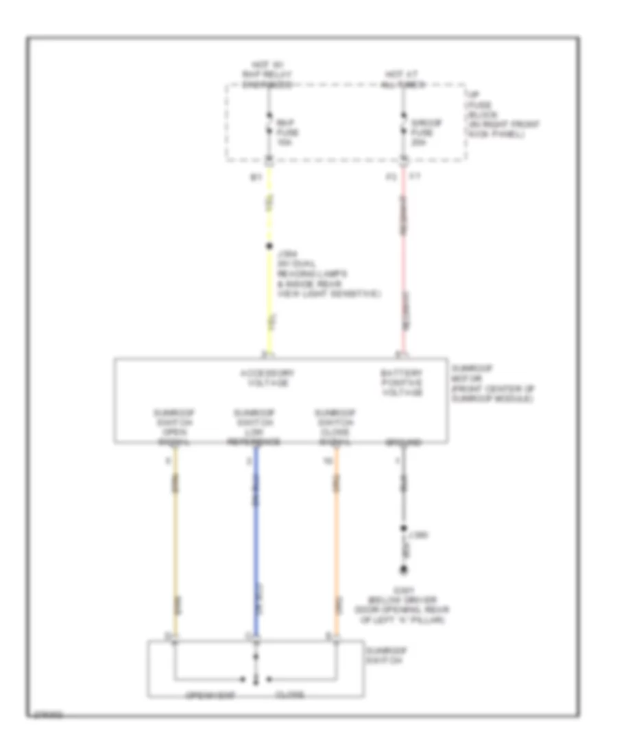 https://portal-diagnostov.com/license.html
Automotive Electricians Portal FZCO
Automotive Electricians Portal FZCO
https://portal-diagnostov.com/license.html
https://portal-diagnostov.com/license.html
Automotive Electricians Portal FZCO
Automotive Electricians Portal FZCOList of elements for Power Top/Sunroof Wiring Diagram for Chevrolet Impala LS 2008:
- Accessory voltage
- Battery positive voltage
- Close
- G301 (below driver door opening, rear of left "a" pillar)
- Ground
- Hot at all times
- Hot w/ rap relay energized
- I/p fuse block (in right front kick panel)
- J364 (w/ dual reading lamps & inside rear view light sensitive)
- J390
- Open/vent
- Rap fuse 10a
- S/roof fuse 20a
- Sunroof motor (front center of sunroof module)
- Sunroof switch
- Sunroof switch close signal
- Sunroof switch low reference
- Sunroof switch open signal
POWER WINDOWS
Power Windows Wiring Diagram for Chevrolet Impala LS 2008
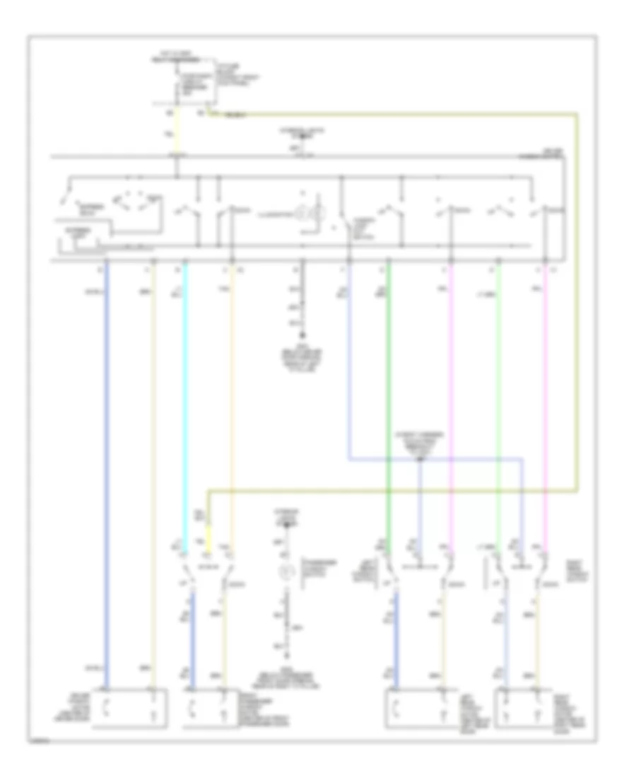 https://portal-diagnostov.com/license.html
Automotive Electricians Portal FZCO
Automotive Electricians Portal FZCO
https://portal-diagnostov.com/license.html
https://portal-diagnostov.com/license.html
Automotive Electricians Portal FZCO
Automotive Electricians Portal FZCOList of elements for Power Windows Wiring Diagram for Chevrolet Impala LS 2008:
- (in body harness, 16.5 cm from breakout to x301) j307
- Down
- Driver window motor (center of driver door)
- Driver window switch
- Express down
- Express logic
- Front passenger window motor (center of front passenger door)
- G301 (below driver door opening, rear of left "a" pillar)
- G302 (below passenger front door opening, rear of right "a" pillar)
- Hot w/ rap relay energized
- I/p fuse block (in right front kick panel)
- Illumination
- Interior lights system
- J504
- J604
- Left rear window motor (center of left rear door)
- Left rear window switch
- Passenger window switch
- Pwr/wndw circuit breaker 25a
- Right rear window motor (center of right rear door)
- Right rear window switch
- Tan
- Window lock out switch
RADIO
Radio Wiring Diagram, Police Option (1 of 2) for Chevrolet Impala LS 2008
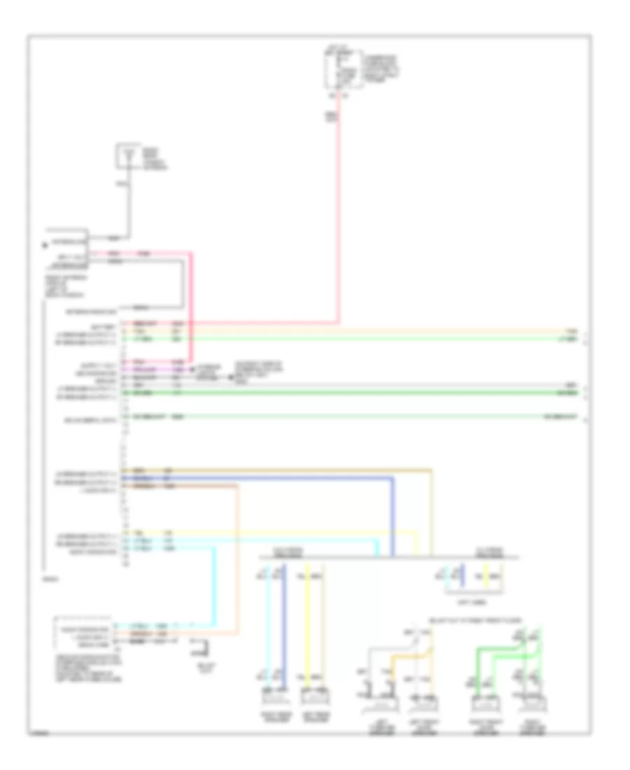 https://portal-diagnostov.com/license.html
Automotive Electricians Portal FZCO
Automotive Electricians Portal FZCO
https://portal-diagnostov.com/license.html
https://portal-diagnostov.com/license.html
Automotive Electricians Portal FZCO
Automotive Electricians Portal FZCOList of elements for Radio Wiring Diagram, Police Option (1 of 2) for Chevrolet Impala LS 2008:
- (not used)
- (on right side of steering column below x201) g202
- Antenna radio sig
- Antenna sig
- Audio common sig
- Bare
- Battery
- Coax
- Drain wire
- Gmlan serial data
- Ground
- Hot at all times
- Interior lights system
- L audio sig (+)
- Led dimming sig
- Left front door speaker
- Left rear speaker
- Left tweeter speaker
- Lf speaker output (+)
- Lf speaker output (-)
- Lr speaker output (+)
- Lr speaker output (-)
- Nca
- Pnk
- Radio
- Radio antenna module (left of back window)
- Radio fuse 20a
- Radio rear window antenna
- Rf speaker output (+)
- Rf speaker output (-)
- Right front door speaker
- Right rear speaker
- Right tweeter speaker
- Rr speaker output (+)
- Rr speaker output (-)
- Sply volt
- Tan
- Underhood fuse block (mounted to right strut tower)
- Vehicle communication interface module (vcim) (if equipped) (mounted to rear of left rear wheelhouse)
- W/ wiring provision
- W/o wiring provision
- X2 g2
Radio Wiring Diagram, Police Option (2 of 2) for Chevrolet Impala LS 2008
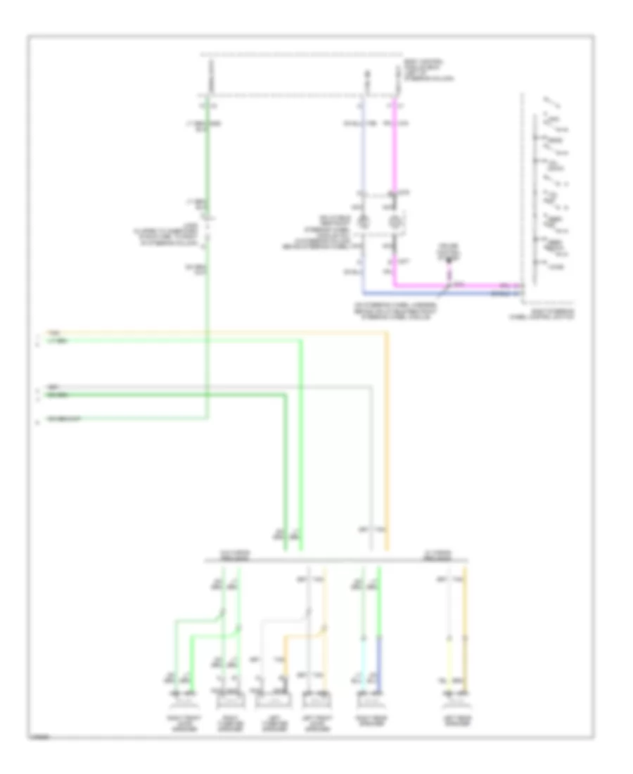 https://portal-diagnostov.com/license.html
Automotive Electricians Portal FZCO
Automotive Electricians Portal FZCO
https://portal-diagnostov.com/license.html
https://portal-diagnostov.com/license.html
Automotive Electricians Portal FZCO
Automotive Electricians Portal FZCOList of elements for Radio Wiring Diagram, Police Option (2 of 2) for Chevrolet Impala LS 2008:
- (on steering wheel harness, behind inflatable restraint steering wheel module)
- Body control module (bcm) (left of steering column)
- Cruise control system
- Ctrl sig
- Inflatable restraint steering wheel module coil (in steering column behind steering wheel)
- Info
- J213
- Jx205 (clipped to inner dash structure, to right of steering column)
- Left front door speaker
- Left rear speaker
- Left tweeter speaker
- Nca
- Right front door speaker
- Right rear speaker
- Right steering wheel control switch
- Right tweeter speaker
- Seek down
- Seek up
- Serial data
- Sply volt
- Srce
- Tan
- Voice
- Vol down
- Vol up
- W/ wiring provision
- W/o wiring provision
- X275 e
- X277 e
Radio Wiring Diagram, with Amplifier for Chevrolet Impala LS 2008
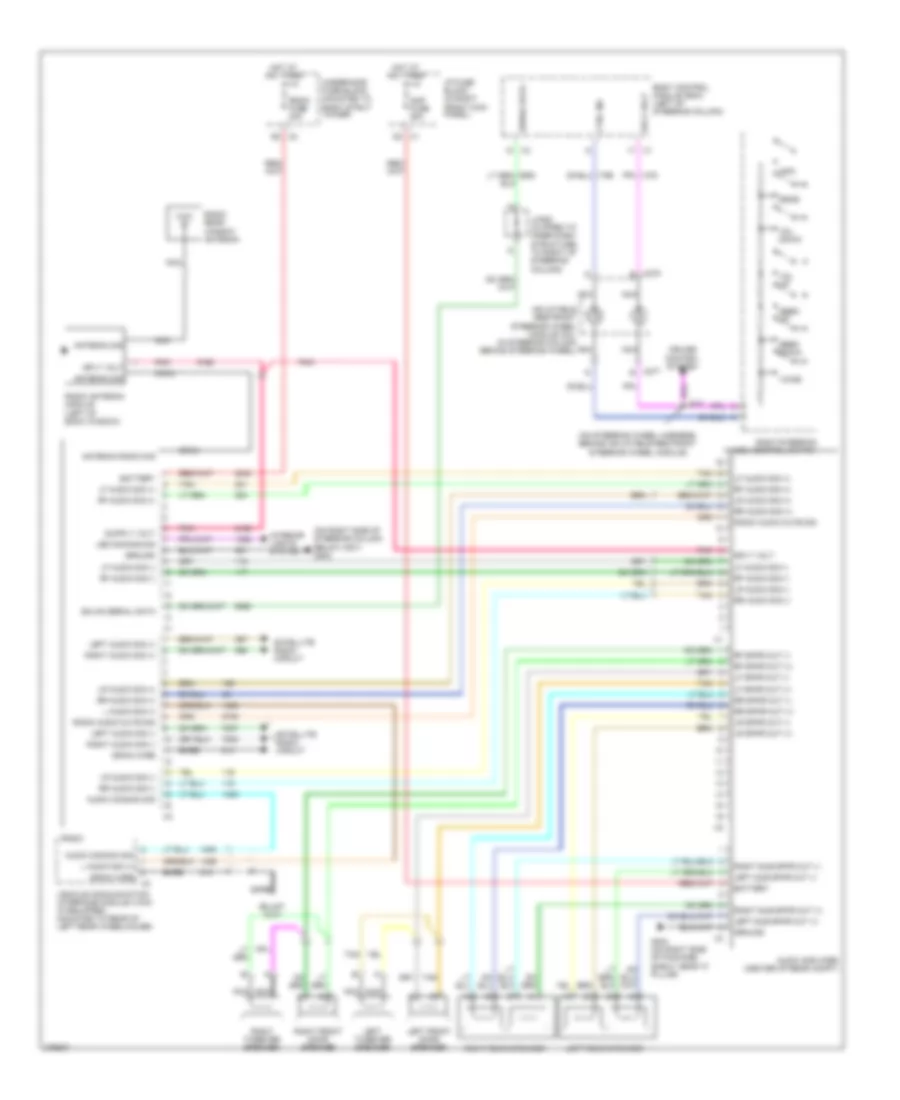 https://portal-diagnostov.com/license.html
Automotive Electricians Portal FZCO
Automotive Electricians Portal FZCO
https://portal-diagnostov.com/license.html
https://portal-diagnostov.com/license.html
Automotive Electricians Portal FZCO
Automotive Electricians Portal FZCOList of elements for Radio Wiring Diagram, with Amplifier for Chevrolet Impala LS 2008:
- (on right side of steering column below x201) g202
- (on steering wheel harness, behind inflatable restraint steering wheel module)
- Amp fuse 25a
- Antenna radio sig
- Antenna sig
- Audio amplifier (center of rear compt)
- Audio common sig
- Bare
- Battery
- Body control module (bcm) (left of steering column)
- Coax
- Cruise control system
- Ctrl sig
- D2 x1
- Drain wire
- G404 (on right side of package shelf, near "c" pillar)
- Gmlan serial data
- Ground
- Hot at all times
- I/p fuse block (in right front kick panel)
- Inflatable restraint steering wheel module coil (in steering column behind steering wheel)
- Info
- Interior lights system
- J213
- Jx205 (clipped to inner dash structure, to right of steering column)
- L audio sig (+)
- Led dimming sig
- Left audio sig (+)
- Left audio sig (-)
- Left front door speaker
- Left rear speaker
- Left sub spkr out (+)
- Left sub spkr out (-)
- Left tweeter speaker
- Lf audio sig (+)
- Lf audio sig (-)
- Lf spkr out (+)
- Lf spkr out (-)
- Lr audio sig (+)
- Lr audio sig (-)
- Lr spkr out (+)
- Lr spkr out (-)
- Nca
- Pnk
- Radio
- Radio antenna module (left of back window)
- Radio audio mute sig
- Radio fuse 20a
- Radio rear window antenna
- Rf audio sig (+)
- Rf audio sig (-)
- Rf spkr out (+)
- Rf spkr out (-)
- Right audio sig (+)
- Right audio sig (-)
- Right front door speaker
- Right rear speaker
- Right steering wheel control switch
- Right sub spkr out (+)
- Right sub spkr out (-)
- Right tweeter speaker
- Rr audio sig (+)
- Rr audio sig (-)
- Rr spkr out (+)
- Rr spkr out (-)
- Satellite radio circuit
- Seek down
- Seek up
- Serial data
- Sply volt
- Srce
- Tan
- Underhood fuse block (mounted to right strut tower)
- Vehicle communication interface module (vcim) (if equipped) (mounted to rear of left rear wheelhouse)
- Voice
- Vol down
- Vol up
- X2 g2
- X275 e
- X277 e
Radio Wiring Diagram, without Amplifier for Chevrolet Impala LS 2008
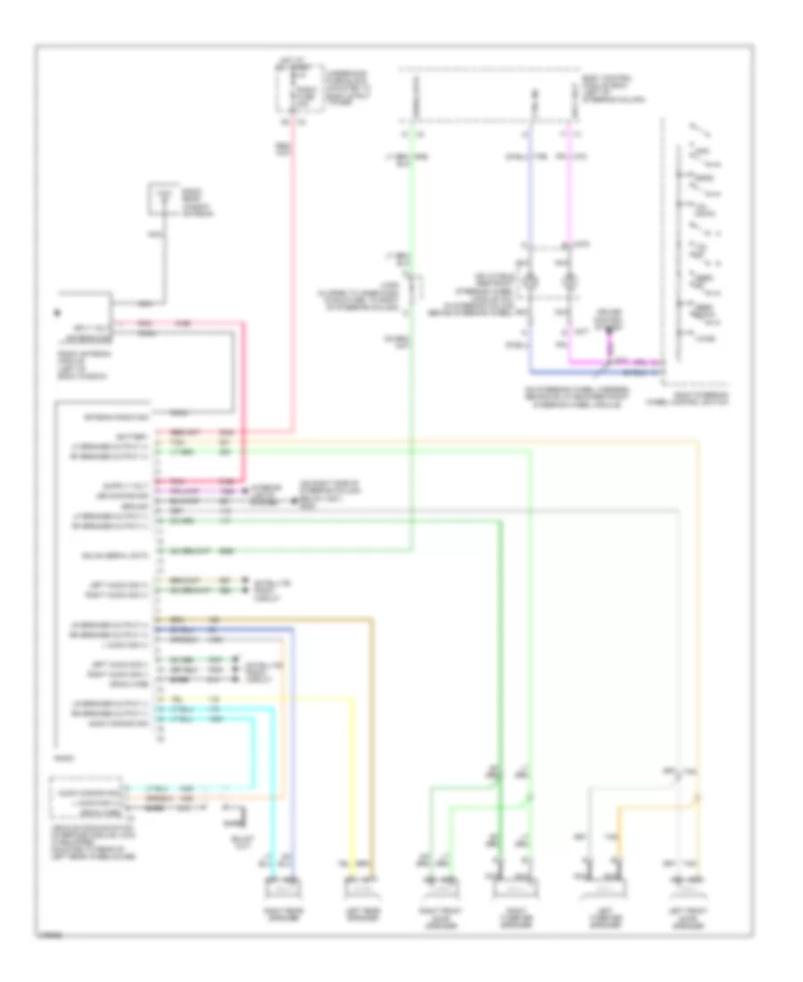 https://portal-diagnostov.com/license.html
Automotive Electricians Portal FZCO
Automotive Electricians Portal FZCO
https://portal-diagnostov.com/license.html
https://portal-diagnostov.com/license.html
Automotive Electricians Portal FZCO
Automotive Electricians Portal FZCOList of elements for Radio Wiring Diagram, without Amplifier for Chevrolet Impala LS 2008:
- (on right side of steering column below x201) g202
- (on steering wheel harness, behind inflatable restraint steering wheel module)
- Antenna radio sig
- Antenna sig
- Audio common sig
- Bare
- Battery
- Body control module (bcm) (left of steering column)
- Coax
- Cruise control system
- Ctrl sig
- Drain wire
- G2 x2
- Gmlan serial data
- Ground
- Hot at all times
- Inflatable restraint steering wheel module coil (in steering column behind steering wheel)
- Info
- Interior lights system
- J213
- Jx205 (clipped to inner dash structure, to right of steering column)
- L audio sig (+)
- Led dimming sig
- Left audio sig (+)
- Left audio sig (-)
- Left front door speaker
- Left rear speaker
- Left tweeter speaker
- Lf speaker output (+)
- Lf speaker output (-)
- Lr speaker output (+)
- Lr speaker output (-)
- Nca
- Pnk
- Radio
- Radio antenna module (left of back window)
- Radio fuse 20a
- Radio rear window antenna
- Rf speaker output (+)
- Rf speaker output (-)
- Right audio sig (+)
- Right audio sig (-)
- Right front door speaker
- Right rear speaker
- Right steering wheel control switch
- Right tweeter speaker
- Rr speaker output (+)
- Rr speaker output (-)
- Satellite radio circuit
- Seek down
- Seek up
- Serial data
- Sply volt
- Srce
- Tan
- Underhood fuse block (mounted to right strut tower)
- Vehicle communication interface module (vcim) (if equipped) (mounted to rear of left rear wheelhouse)
- Voice
- Vol down
- Vol up
- X275 e
- X277 e
Satellite Radio Wiring Diagram for Chevrolet Impala LS 2008
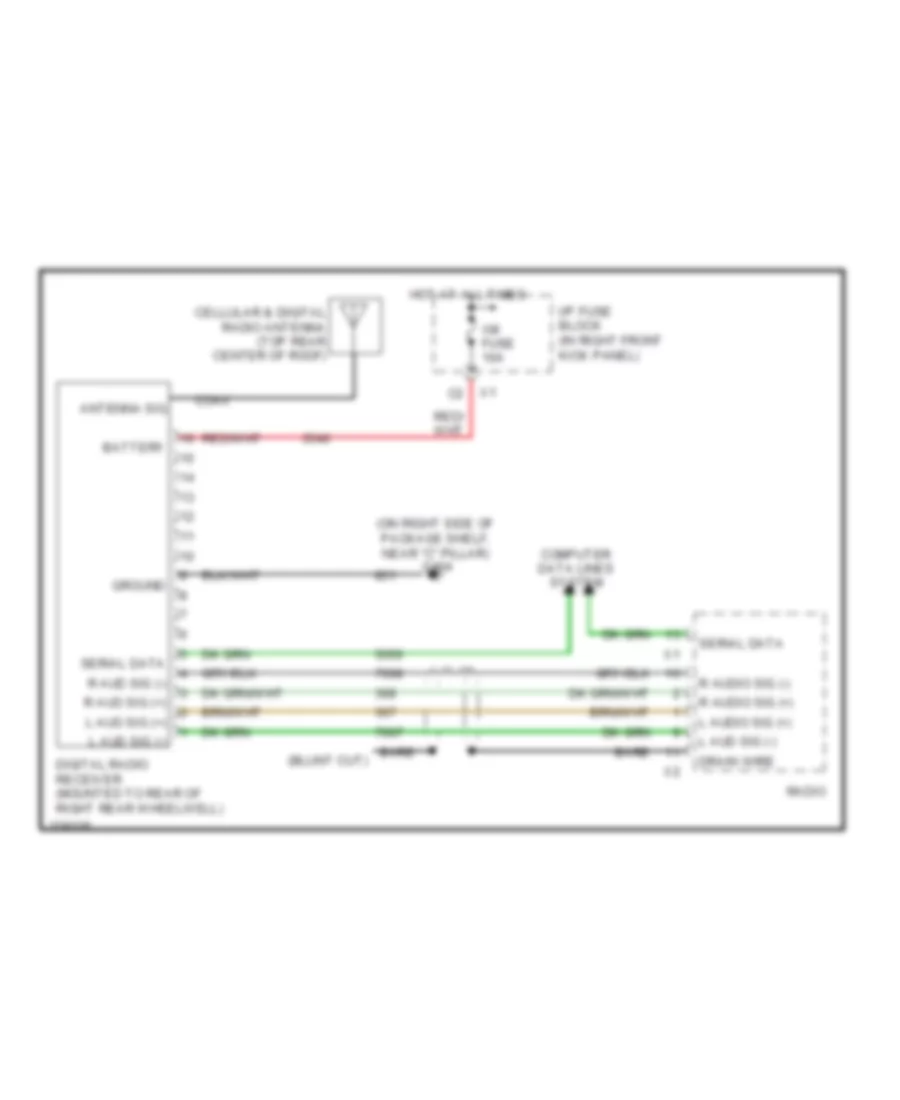 https://portal-diagnostov.com/license.html
Automotive Electricians Portal FZCO
Automotive Electricians Portal FZCO
https://portal-diagnostov.com/license.html
https://portal-diagnostov.com/license.html
Automotive Electricians Portal FZCO
Automotive Electricians Portal FZCOList of elements for Satellite Radio Wiring Diagram for Chevrolet Impala LS 2008:
- (on right side of package shelf, near "c" pillar) g404
- Antenna sig
- Bare
- Battery
- Cellular & digital radio antenna (top rear center of roof)
- Coax
- Computer data lines system
- Digital radio receiver (mounted to rear of right rear wheelwell)
- Drain wire
- Ground
- Hot at all times
- I/p fuse block (in right front kick panel)
- L aud sig (+)
- L aud sig (-)
- L audio sig (+)
- R aud sig (+)
- R aud sig (-)
- R audio sig (+)
- R audio sig (-)
- Radio
- Serial data
- Xm fuse 10a
SHIFT INTERLOCK
Ignition Lock Solenoid Wiring Diagram for Chevrolet Impala LS 2008
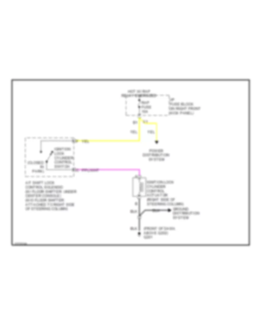 https://portal-diagnostov.com/license.html
Automotive Electricians Portal FZCO
Automotive Electricians Portal FZCO
https://portal-diagnostov.com/license.html
https://portal-diagnostov.com/license.html
Automotive Electricians Portal FZCO
Automotive Electricians Portal FZCOList of elements for Ignition Lock Solenoid Wiring Diagram for Chevrolet Impala LS 2008:
- (closed in park)
- (front of dash, above g202) g201
- A/t shift lock control solenoid (w/ floor shifter: under center console) (w/o floor shifter: attached to right side of steering column)
- Ground distribution system
- Hot w/ rap relay energized
- I/p fuse block (in right front kick panel)
- Ignition lock cylinder control actuator (right side of steering column)
- Ignition lock cylinder control switch
- Power distribution system
- Rap fuse 10a
Shift Interlock Wiring Diagram for Chevrolet Impala LS 2008
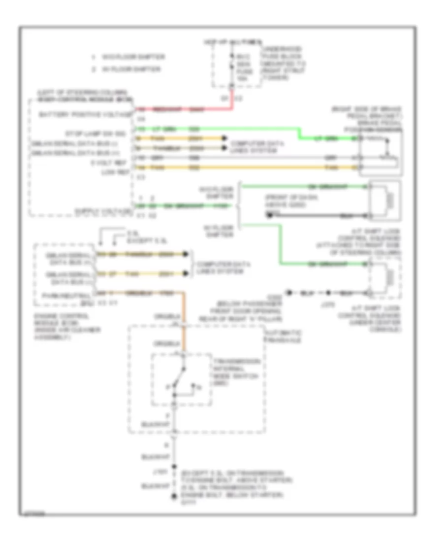 https://portal-diagnostov.com/license.html
Automotive Electricians Portal FZCO
Automotive Electricians Portal FZCO
https://portal-diagnostov.com/license.html
https://portal-diagnostov.com/license.html
Automotive Electricians Portal FZCO
Automotive Electricians Portal FZCOList of elements for Shift Interlock Wiring Diagram for Chevrolet Impala LS 2008:
- (except 5.3l: on transmission to engine bolt, above starter) (5.3l: on transmission to engine bolt, below starter) g111
- (front of dash, above g202)
- (left of steering column)
- (right side of brake pedal bracket) brake pedal position sensor
- 5 volt ref
- 5.3l except 5.3l
- A/t shift lock control solenoid (attached to right side of steering column)
- A/t shift lock control solenoid (under center console)
- Automatic transaxle
- Battery positive voltage
- Body control module (bcm)
- Computer data
- Computer data lines system
- Engine control module (ecm) (inside air cleaner assembly)
- G201
- G302 (below passenger front door opening,
- Gmlan serial data bus (+)
- Gmlan serial data bus (-)
- Hot at all times
- J101
- J375
- Lines system
- Low ref
- Park/neutral sig x3
- Rear of right "a" pillar)
- Rvc sen fuse 10a
- Stop lamp sw sig
- Tan
- Transmission internal mode switch (ims)
- Underhood fuse block (mounted to right strut tower)
- W/ floor shifter
- W/o floor shifter
STARTING/CHARGING
Charging Wiring Diagram for Chevrolet Impala LS 2008
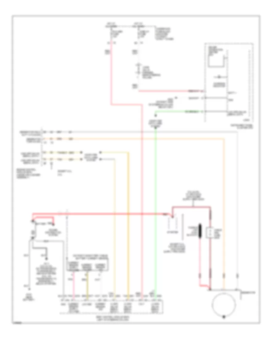 https://portal-diagnostov.com/license.html
Automotive Electricians Portal FZCO
Automotive Electricians Portal FZCO
https://portal-diagnostov.com/license.html
https://portal-diagnostov.com/license.html
Automotive Electricians Portal FZCO
Automotive Electricians Portal FZCOList of elements for Charging Wiring Diagram for Chevrolet Impala LS 2008:
- (on positive battery cable) battery current sensor
- 5.3l
- Batt +
- Battery
- Body control module (bcm) (left of steering column)
- Cable pro fuse 200a
- Charging indicator
- Computer data lines system
- Current sensor low ref
- Current sensor sig
- Display fuse 10a
- Driver information center (dic)
- Engine control module (ecm) (inside air cleaner assembly)
- Except 5.3l
- G102 (near battery)
- G111 (3.5l & 3.9l: on transmission to engine bolt, above starter) (5.3l: on transmission to engine bolt, below starter)
- G202 (on right side of steering column below x201)
- Generator
- Generator field duty cycle sig
- Generator turn on sig
- Gnd
- Hi spd gmlan serial data +
- Hi spd gmlan serial data -
- High spd gmlan serial data +
- High spd gmlan serial data -
- Hot at all times
- Instrument panel cluster (ipc)
- Jx206 (on i/p harness, near steering column)
- Lo spd gmlan serial data
- Logic
- Low ref
- Low spd gmlan serial data
- Pnk
- Power distribution system
- Red
- Rvc sen fuse 10a
- Starter
- Tan
- Underhood fuse block (mounted to right strut tower)
- Volt
Starting Wiring Diagram for Chevrolet Impala LS 2008
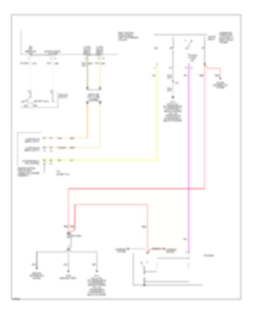 https://portal-diagnostov.com/license.html
Automotive Electricians Portal FZCO
Automotive Electricians Portal FZCO
https://portal-diagnostov.com/license.html
https://portal-diagnostov.com/license.html
Automotive Electricians Portal FZCO
Automotive Electricians Portal FZCOList of elements for Starting Wiring Diagram for Chevrolet Impala LS 2008:
- 5.3l
- Acc
- Battery
- Body control module (bcm) (left of steering column)
- Charging system
- Computer data lines system
- Engine control module (ecm) (inside air cleaner assembly)
- Except 5.3l
- G102 (near battery)
- G111 (3.5l & 3.9l: on transmission to engine bolt, above starter) (5.3l: on transmission to engine bolt, below starter)
- Ground distribution system
- Hi spd gmlan serial data +
- Hi spd gmlan serial data -
- Ign key resistor sig
- Ignition switch
- J101
- Off
- Off/run crank voltage
- Power distribution system
- Red
- Run
- Start
- Starter
- Starter relay coil control
- Strtr fuse 40a
- Strtr relay
- Tan
- Tan/
- Underhood fuse block (mounted to right strut tower)
SUPPLEMENTAL RESTRAINTS
Supplemental Restraints Wiring Diagram (1 of 3) for Chevrolet Impala LS 2008
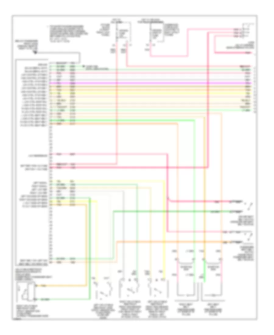 https://portal-diagnostov.com/license.html
Automotive Electricians Portal FZCO
Automotive Electricians Portal FZCO
https://portal-diagnostov.com/license.html
https://portal-diagnostov.com/license.html
Automotive Electricians Portal FZCO
Automotive Electricians Portal FZCOList of elements for Supplemental Restraints Wiring Diagram (1 of 3) for Chevrolet Impala LS 2008:
- (below passenger front door opening, rear of right "a" pillar) g302
- Air bag fuse 10a
- Air bag/ display fuse 10a
- Battery pos voltage
- Computer data lines system
- Driver seat belt switch (inside driver seat belt buckle)
- Gmlan serial data
- Ground
- High control stage 1
- High control stage 2
- High ctrl i/p stage 1
- High ctrl i/p stage 2
- Hot at all times
- Hot w/ ign main pcb relay energized
- I/p fuse block (in right front kick panel)
- Ignition 1 voltage
- Inflatable restraint sensing & diagnostic
- Jx206 (on i/p harness, near steering column)
- L high ctrl roof rail
- L high ctrl seat belt
- L low ctrl roof rail
- L low ctrl seat belt
- L volt side imp sens
- Left inflatable restraint front end sensor (front left of car, rear of front fascia, left of hood latch)
- Left inflatable restraint side impact sensor (sis) (if equipped) (in driver door)
- Left low ref
- Left seat belt pretensioner (at base of "b" pillar)
- Left sig side imp sens
- Left signal
- Low control stage 1
- Low control stage 2
- Low ctrl i/p stage 1
- Low ctrl i/p stage 2
- Low reference
- Module (sdm) (under front passenger seat, under carpet)
- Nca
- Passenger seat belt switch (inside front passenger seat belt buckle)
- Pin shorting bars engaged
- Pnk
- R high ctrl roof rail
- R high ctrl seat belt
- R low ctrl roof rail
- R low ctrl seat belt
- R volt side imp sens
- Right inflatable restraint front end sensor (front right of car, rear of front fascia, right of hood latch)
- Right inflatable restraint side impact sensor (sis) (if equipped) (in front passenger door)
- Right low ref
- Right seat belt pretensioner (at base of "b" pillar)
- Right sig side imp sens
- Right signal
- Seat belt sw left sig
- Seat belt sw right sig
- Shorting bar
- Tan
- Underhood fuse block (mounted to right strut tower)
- When module connector is disconnected from harness: (shorting bars are connected between following pins: 6-7, 10-11, 12-13, 14-15, 16-17, 18-19)
Supplemental Restraints Wiring Diagram (2 of 3) for Chevrolet Impala LS 2008
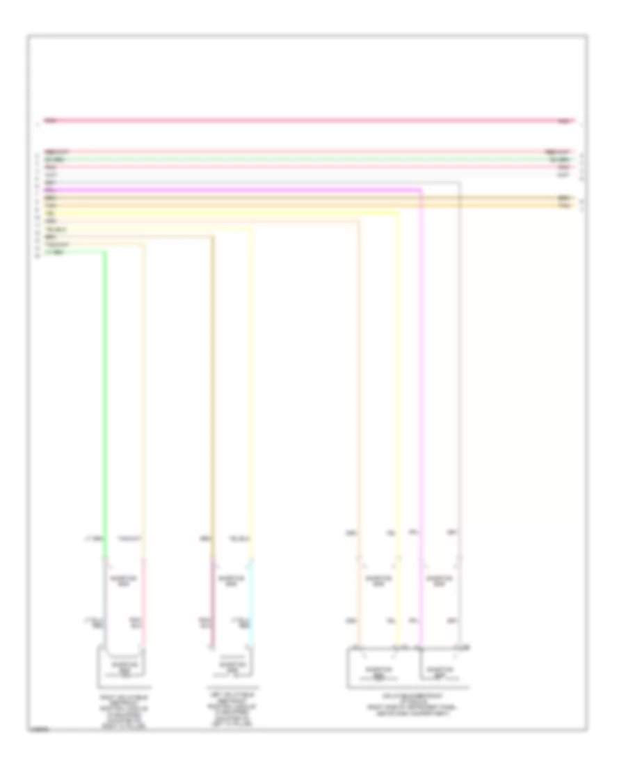 https://portal-diagnostov.com/license.html
Automotive Electricians Portal FZCO
Automotive Electricians Portal FZCO
https://portal-diagnostov.com/license.html
https://portal-diagnostov.com/license.html
Automotive Electricians Portal FZCO
Automotive Electricians Portal FZCOList of elements for Supplemental Restraints Wiring Diagram (2 of 3) for Chevrolet Impala LS 2008:
- Inflatable restraint i/p module (right side of instrument panel, above dash compartment)
- Left inflatable restraint roof rail module (if equipped) (mounted on left "c" pillar)
- Pnk
- Right inflatable restraint roof rail module (if equipped) (mounted on right "c" pillar)
- Shorting bar
- Tan
Supplemental Restraints Wiring Diagram (3 of 3) for Chevrolet Impala LS 2008
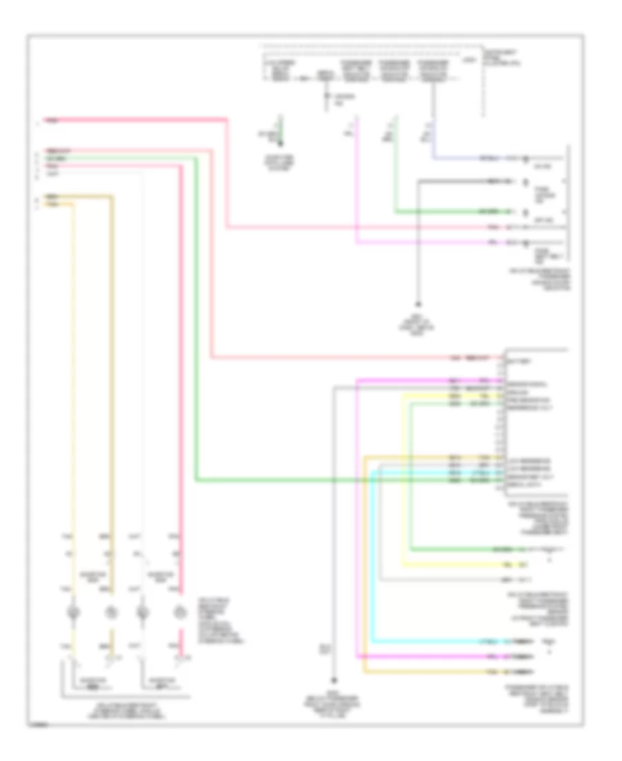 https://portal-diagnostov.com/license.html
Automotive Electricians Portal FZCO
Automotive Electricians Portal FZCO
https://portal-diagnostov.com/license.html
https://portal-diagnostov.com/license.html
Automotive Electricians Portal FZCO
Automotive Electricians Portal FZCOList of elements for Supplemental Restraints Wiring Diagram (3 of 3) for Chevrolet Impala LS 2008:
- Air bag
- Battery
- Computer data lines system
- G201 (front of dash, above g202)
- G302 (below passenger front door opening, rear of right "a" pillar)
- Ground
- Ign
- Ind
- Inflatable restraint front passenger presence system (pps) module (under front passenger seat)
- Inflatable restraint front passenger presence system sensor (in front passenger seat cushion)
- Inflatable restraint passenger air bag on/off indicator
- Inflatable restraint steering wheel module (center of steering wheel)
- Inflatable restraint steering wheel module coil (in steering column behind steering wheel)
- Instrument panel cluster (ipc)
- Logic
- Low reference
- Low speed gmlan serial data
- Nca
- Off ind
- On ind
- Pass air bag ind
- Pass seat belt ind
- Passenger air bag off indicator control
- Passenger air bag on indicator control
- Passenger inflatable restraint seat belt tension sensor (part of buckle assembly)
- Passenger seat belt indicator control
- Pnk
- Pre sensor sig
- Reference volt
- Sensor ref volt
- Sensor signal
- Serial data
- Shorting bar
- Tan
TRANSMISSION
Transmission Wiring Diagram for Chevrolet Impala LS 2008
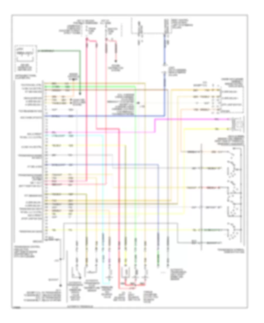 https://portal-diagnostov.com/license.html
Automotive Electricians Portal FZCO
Automotive Electricians Portal FZCO
https://portal-diagnostov.com/license.html
https://portal-diagnostov.com/license.html
Automotive Electricians Portal FZCO
Automotive Electricians Portal FZCOList of elements for Transmission Wiring Diagram for Chevrolet Impala LS 2008:
- (5.3l: in engine wiring harness, 5.5 cm from breakout to starter) (except 5.3l: in engine wiring harness, 5 cm from x100 breakout towards starter)
- (inside air cleaner assembly) engine control module (ecm)
- 1-2 shift solenoid (ss) valve
- 1-2 ss valve ctrl
- 2-3 shift solenoid (ss) valve
- 2-3 ss valve ctrl
- 5.3l
- Acc wake up data
- Acc wakeup serial data
- At iss high sig
- At iss lo sig
- Automatic transaxle
- Automatic transmission fluid pressure manual valve position switch
- Automatic transmission fluid temperature sensor
- Automatic transmission input shaft speed (iss) sensor
- Batt positive volt
- Body control module (bcm) (left of steering column)
- Computer data lines system
- Driver information center (dic)
- Ecm/tcm fuse 15a
- Engine controls system
- Except 5.3l
- G111 (except 5.3l: on transmission to engine bolt, above starter) (5.3l: on transmission to engine bolt, below starter)
- Ground
- Hi spd gmlan +
- Hi spd gmlan -
- Hot at all times
- Hot w/ ign main pcb relay energized
- Ign 1 volt
- Instrument panel cluster (ipc)
- J101
- J105
- J115
- Jx207 (on i/p harness, near steering column)
- Logic
- P/n sig
- Pc sol vlv hi ctrl
- Pc sol vlv lo ctrl
- Pnk
- Power distribution system
- Pressure control (pc) solenoid valve
- Red
- Serial data
- Sig hi front
- Sig lo front
- Stop lamp sw sig
- Stp lamp switch
- Tan
- Tan b
- Tcc pwn sol ctrl
- Tcc release sw sig
- Tft sensor sig
- Torque converter clutch (tcc) solenoid valve
- Trans fuse 10a
- Trans ran sw sig b
- Trans ran sw sig p
- Transmission control module (tcm) (left side of engine compartment in with air cleaner)
- Transmission internal mode switch (ims)
- Transmission range sw sig a low ref
- Transmission range sw sig c
- Underhood fuse block (mounted to right strut tower)
- Vehicle spd sig
- Vehicle speed sensor (vss) assembly (right side of transaxle, near right axle shaft)
TRUNK, TAILGATE, FUEL DOOR
Trunk Release Wiring Diagram for Chevrolet Impala LS 2008
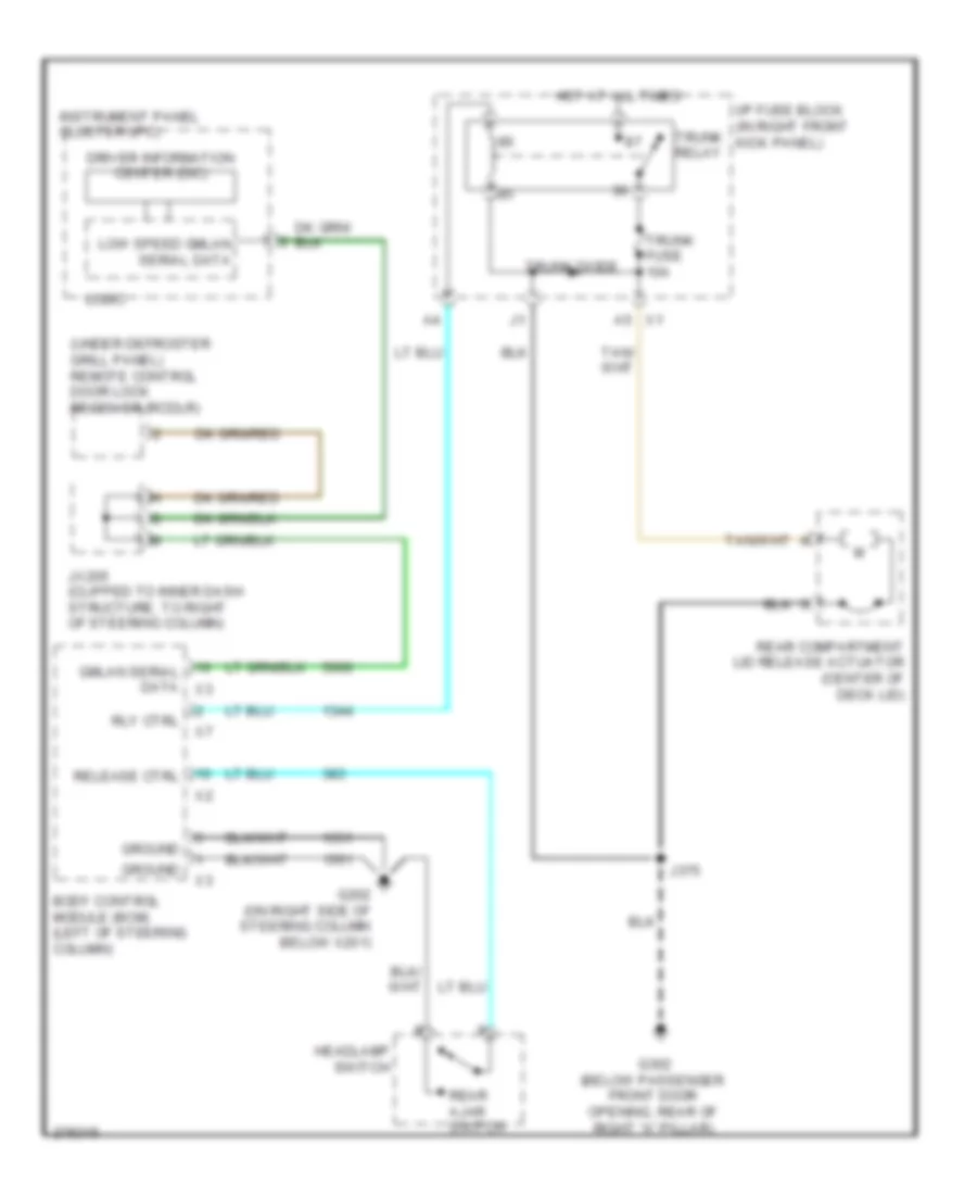 https://portal-diagnostov.com/license.html
Automotive Electricians Portal FZCO
Automotive Electricians Portal FZCO
https://portal-diagnostov.com/license.html
https://portal-diagnostov.com/license.html
Automotive Electricians Portal FZCO
Automotive Electricians Portal FZCOList of elements for Trunk Release Wiring Diagram for Chevrolet Impala LS 2008:
- (under defroster grill panel) remote control door lock receiver (rcdlr)
- A5 x1
- Body control module (bcm) (left of steering column)
- Driver information center (dic)
- G202 (on right side of steering column below x201)
- G302 (below passenger front door opening, rear of right "a" pillar)
- Gmlan serial data x3
- Ground
- Headlamp switch
- Hot at all times
- I/p fuse block (in right front kick panel)
- Instrument panel cluster (ipc)
- J375
- Jx205 (clipped to inner dash structure, to right of steering column)
- Logic
- Low speed gmlan serial data
- Rear ajar switch
- Rear compartment lid release actuator (center of deck lid)
- Release ctrl
- Rly ctrl
- Trunk diode
- Trunk fuse 10a
- Trunk relay
WARNING SYSTEMS
Warning Systems Wiring Diagram for Chevrolet Impala LS 2008
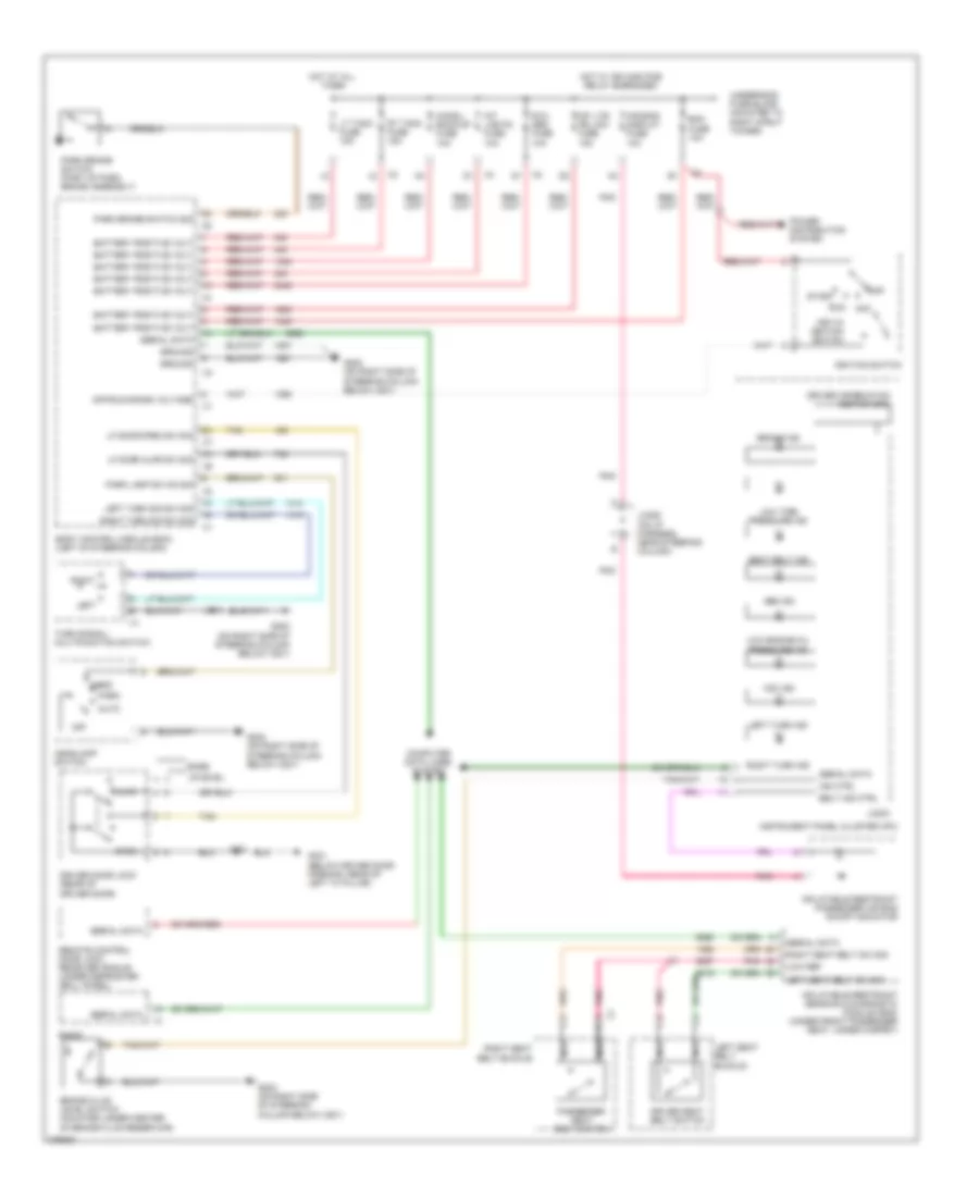 https://portal-diagnostov.com/license.html
Automotive Electricians Portal FZCO
Automotive Electricians Portal FZCO
https://portal-diagnostov.com/license.html
https://portal-diagnostov.com/license.html
Automotive Electricians Portal FZCO
Automotive Electricians Portal FZCOList of elements for Warning Systems Wiring Diagram for Chevrolet Impala LS 2008:
- Abs ind
- Acc
- Air bag/ display fuse 10a
- Ajar
- Auto
- Base
- Battery positive volt
- Bcm fuse 10a
- Belt ind ctrl
- Body control module (bcm) (left of steering column)
- Brake fluid level switch (mounted under center of brake fluid reservoir)
- Brake ind
- Chmsl/ back-up fuse 10a
- Computer data lines system
- Driver door lock (rear of driver door)
- Driver information center (dic)
- Driver seat belt switch
- G202 (on right side of steering column below x201)
- G301 (below driver door opening, rear of left "a" pillar)
- Ground
- Head
- Headlamp switch
- Hot at all times
- Hot w/ ign main pcb relay energized
- Ignition switch
- Ind ctrl
- Inflatable restraint passenger air bag on/off indicator
- Inflatable restraint sensing & diagnostic module (sdm) (under front passenger seat, under carpet)
- Instrument panel cluster (ipc)
- Int lights fuse 10a
- Int lts/ pnl dim fuse 15a
- J214
- J505
- Jx206 (on i/p harness, near steering column)
- Key-in ignition switch
- Left
- Left seat belt buckle
- Left seat belt sw sig
- Left turn ind
- Left turn sig sw sig
- Lf door ajar sw sig
- Lf door open sw sig
- Logic
- Low engine oil pressure ind
- Low ref
- Low tire pressure ind
- Lt t/sig fuse 15a
- Nca
- Off
- Off/run/crank voltage
- Open
- Park
- Park brake switch (part of park brake assembly)
- Park brake switch sig
- Park lamp sw on sig
- Passenger seat belt switch
- Pnk
- Power distribution system
- Radio
- Remote control door lock receiver (rcdlr) (under defroster grill panel)
- Right
- Right seat belt buckle
- Right seat belt sw sig
- Right turn ind
- Right turn sig sw sig
- Rt t/sig fuse 15a
- Run
- Rvc sen fuse 10a
- Seat belt ind
- Serial data
- Start
- Tan
- Turn signal/ multifunction switch
- Underhood fuse block (mounted to right strut tower)
- Uplevel
- Vdc ind
WIPER/WASHER
Wiper/Washer Wiring Diagram for Chevrolet Impala LS 2008
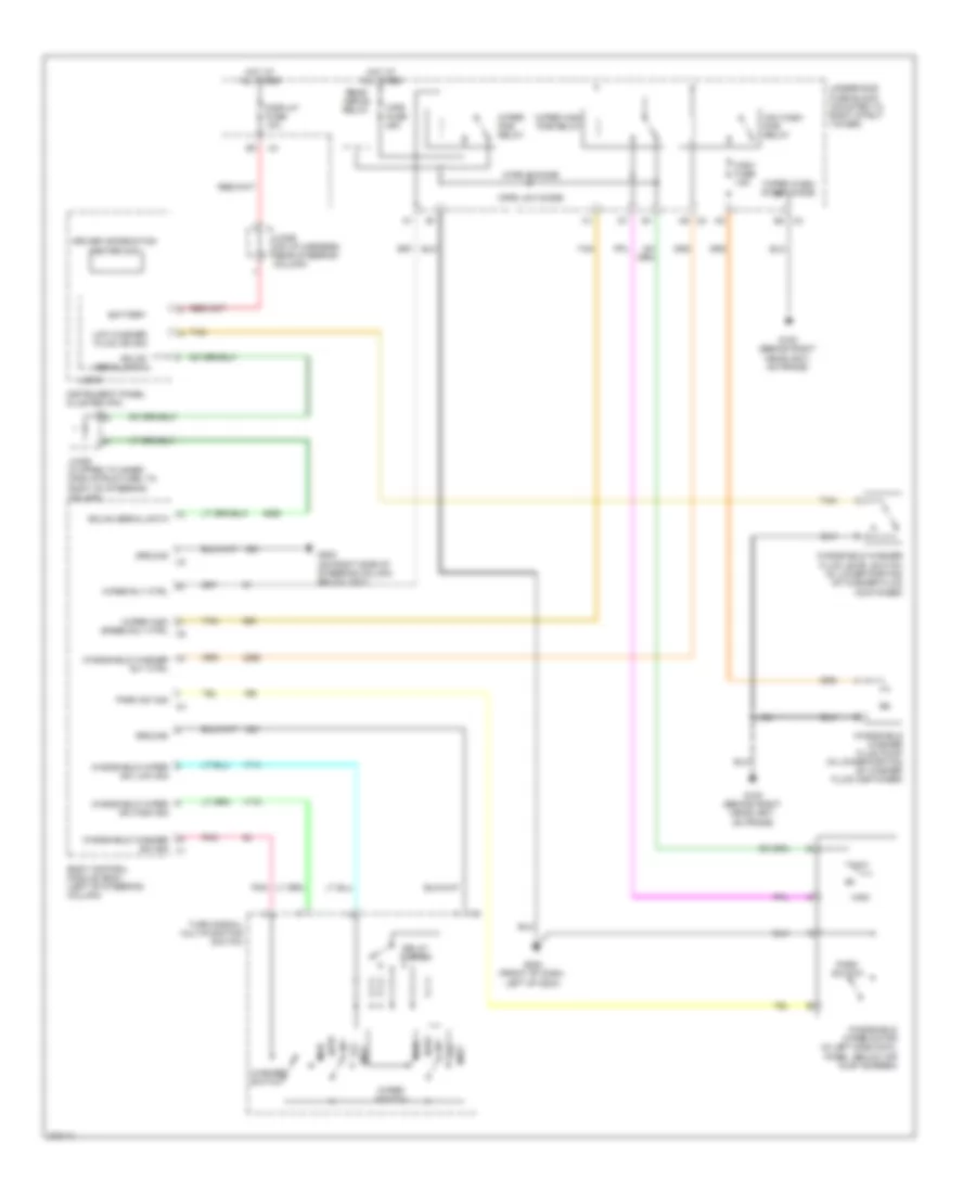 https://portal-diagnostov.com/license.html
Automotive Electricians Portal FZCO
Automotive Electricians Portal FZCO
https://portal-diagnostov.com/license.html
https://portal-diagnostov.com/license.html
Automotive Electricians Portal FZCO
Automotive Electricians Portal FZCOList of elements for Wiper/Washer Wiring Diagram for Chevrolet Impala LS 2008:
- Battery
- Body control module (bcm) (left of steering column)
- Delay switch
- Display fuse 10a
- Driver information center (dic)
- E2 x3
- G100 (behind right headlight, on frame)
- G200 (front of dash, left of g204)
- G202 (on right side of steering column below x201)
- Gmlan serial data
- Ground
- H6 x2
- High
- Hot at all times
- Instrument panel cluster (ipc)
- Int
- J124
- Jx205 (clipped to inner dash structure, to right of steering column)
- Jx206 (on i/p harness, near steering column)
- Logic
- Low
- Low washer fluid ind sig
- Mist
- Off
- Park sw sig
- Park switch
- Pnk
- Rear defog relay
- Speed rly ctrl x5
- Tan
- Turn signal/ multifunction switch
- Underhood fuse block (mounted to right strut tower)
- Washer switch
- Windshield washer fluid level switch (in lower portion of washer fluid container)
- Windshield washer fluid pump (in lower portion of washer fluid container)
- Windshield washer rly ctrl
- Windshield washer sw sig x1
- Windshield wiper motor (in left side cowl panel, below air inlet screen)
- Windshield wiper sw high sig
- Windshield wiper sw low sig
- Wipe hi diode
- Wipe low diode
- Wiper high
- Wiper high pcb relay
- Wiper pcb relay
- Wiper rly ctrl
- Wiper switch
- Wiper wash motor diode
- Wpr fuse 25a
- Ws wash pcb relay
- Wsw fuse 15a

 Čeština
 Dansk
Dansk Deutsch
 Ελληνικά
 English
 English
 Español
 Suomi
Suomi Français
 Français
 עברית
עברית Hrvatski
 Magyar
 Italiano
 日本語
日本語 Nederlands
 Polski
 Português
 Português
 Română
 Русский
 Slovenčina
 Slovenščina
 Svenska
 Türkçe
 中文 (中国)
