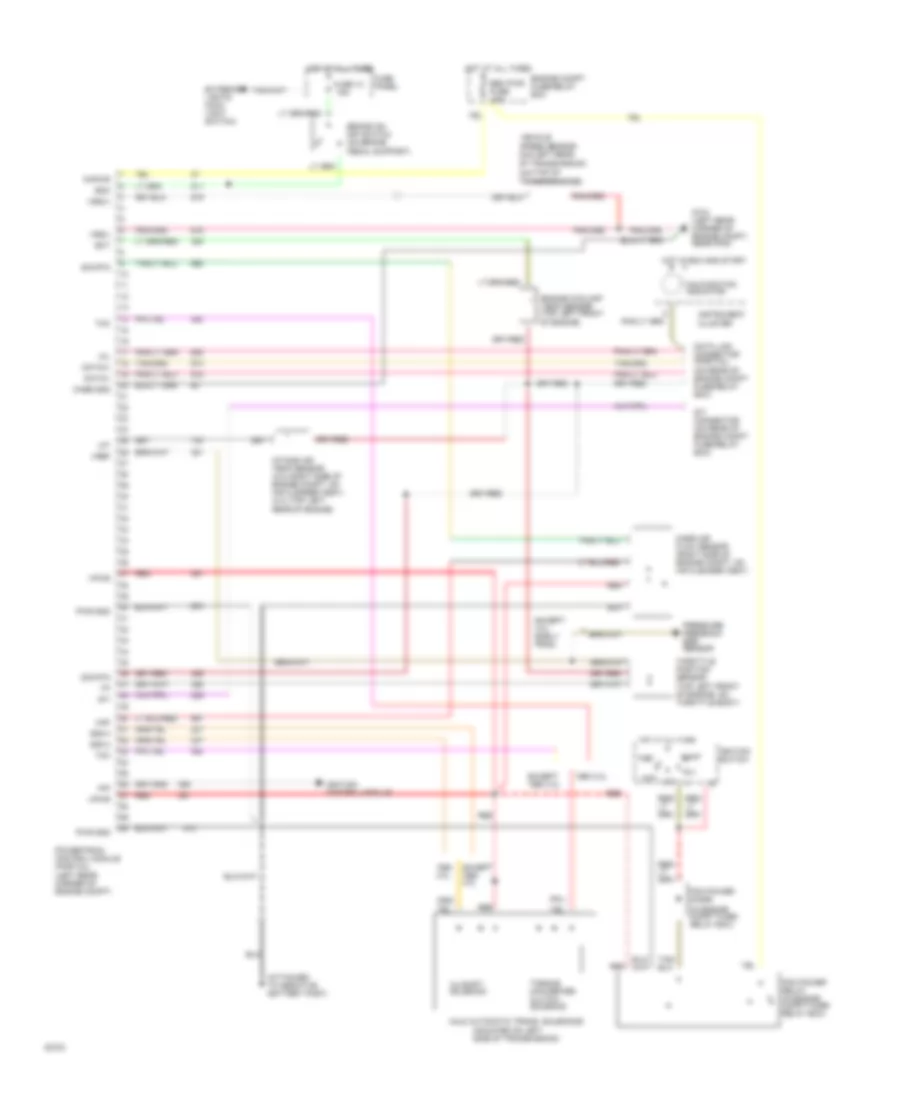
ANTI-LOCK BRAKES
Anti-lock Brake Wiring Diagrams for Ford Ranger 1994
 https://portal-diagnostov.com/license.html
Automotive Electricians Portal FZCO
Automotive Electricians Portal FZCO
https://portal-diagnostov.com/license.html
https://portal-diagnostov.com/license.html
Automotive Electricians Portal FZCO
Automotive Electricians Portal FZCO
List of elements for Anti-lock Brake Wiring Diagrams for Ford Ranger 1994:
- engine compartment on radiator support)
- (left front of
- (on brake pedal support)
- (top center of
- (top of rear differential)
- 4x4
- 4x4 high range indicator
- 4x4 input signal
- Acc
- Anti-lock brakes indicator
- Brake fluid level switch (left rear of engine compartment, on brake fluid reservoir)
- Brake input
- Brake level fluid in
- Brake on/off (boo) switch
- C250
- Dump solenoid out
- Dump valve solenoid
- Electronic shift control switch
- Fuse 15a
- Fuse 20a
- Fuse panel
- G104
- G108
- G203 (behind right cowl panel)
- Ground
- Hot at all times
- Hot in run
- Hot in run or start
- Ignition
- Ignition switch
- Indicator control
- Instrument cluster
- Instrument cluster system
- Instrument cluster system (4x4 ind. switch)
- Iso solenoid out
- Isolation valve solenoid
- Left fender apron)
- Lock
- Low
- Main light switch
- Normal
- Off
- Rabs proportioning valve switch assembly (on left frame rail front of transmission)
- Rabs test connector (behind i/p, near park brake assembly)
- Rabs test connector (on engine compartment fuse/relay box)
- Rabs test/kam
- Rear anti-lock brake module (behind center of i/p below ashtray)
- Rear axle sensor
- Rear axle speed in
- Red
- Red/pnk
- Reset switch
- Run
- Start
- Transmission system (electric shift control module pin 5)
- Valve reset input
- W/electronic shift
- W/o electronic shift
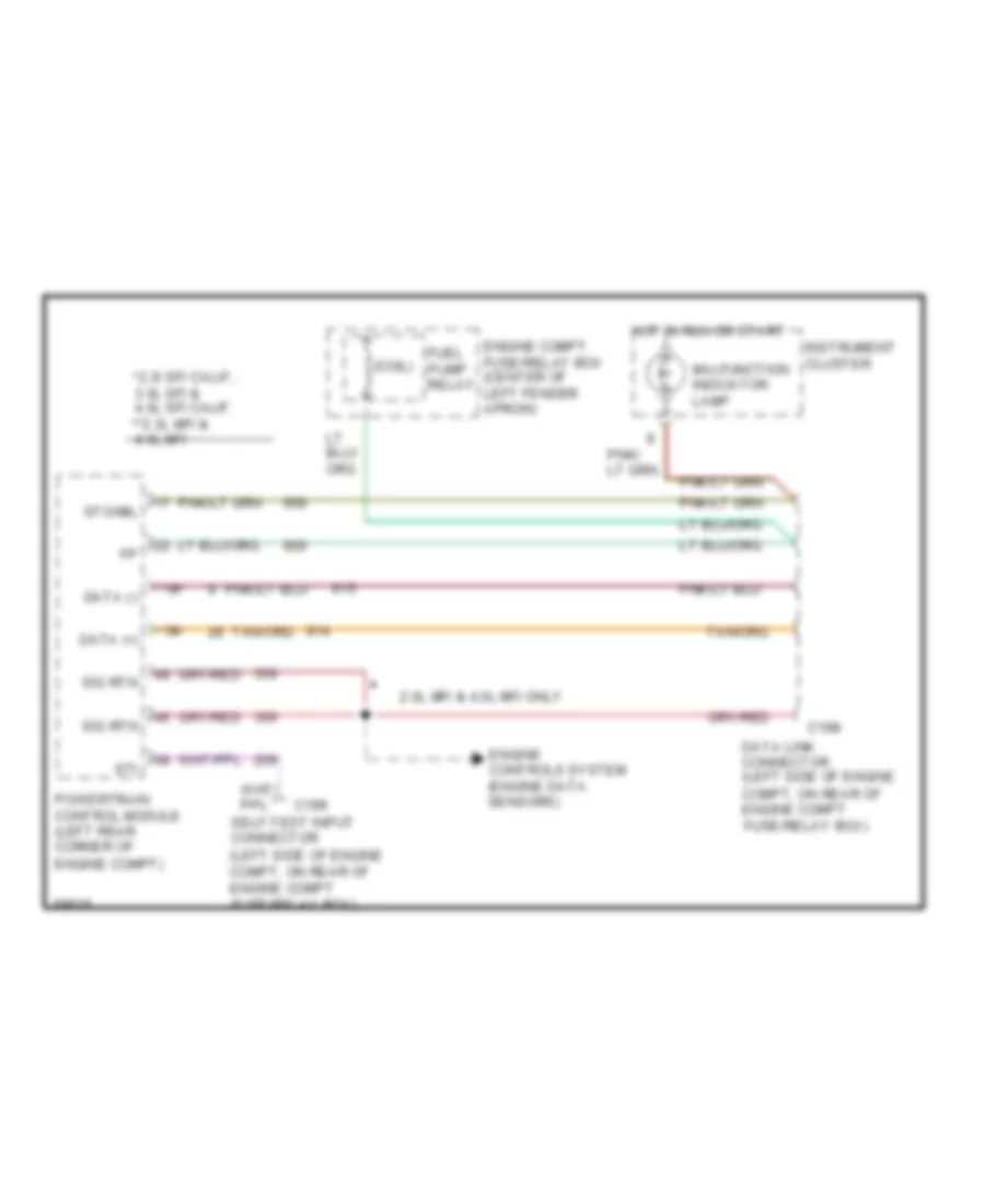
COMPUTER DATA LINES
Data Link Connector Wiring Diagram for Ford Ranger 1994
 https://portal-diagnostov.com/license.html
Automotive Electricians Portal FZCO
Automotive Electricians Portal FZCO
https://portal-diagnostov.com/license.html
https://portal-diagnostov.com/license.html
Automotive Electricians Portal FZCO
Automotive Electricians Portal FZCOList of elements for Data Link Connector Wiring Diagram for Ford Ranger 1994:
- *2.3l sfi calif., 3.0l sfi & 4.0l sfi calif. **2.3l mfi & 4.0l mfi
- (coil)
- * **
- 2.0l mfi & 4.0l mfi only
- C198
- C199
- Data (+)
- Data (-)
- Data link connector (left side of engine compt, on rear of engine compt fuse/relay box)
- Engine compt fuse/relay box (center of left fender apron)
- Engine controls system (engine data sensors)
- Fuel pump relay
- Hot in run or start
- Instrument cluster
- Malfunction indicator lamp
- Powertrain control module (left rear corner of engine compt)
- Self-test input connector (left side of engine compt, on rear of engine compt fuse/relay box)
- Sig rtn
- Sti
- Sto/mil
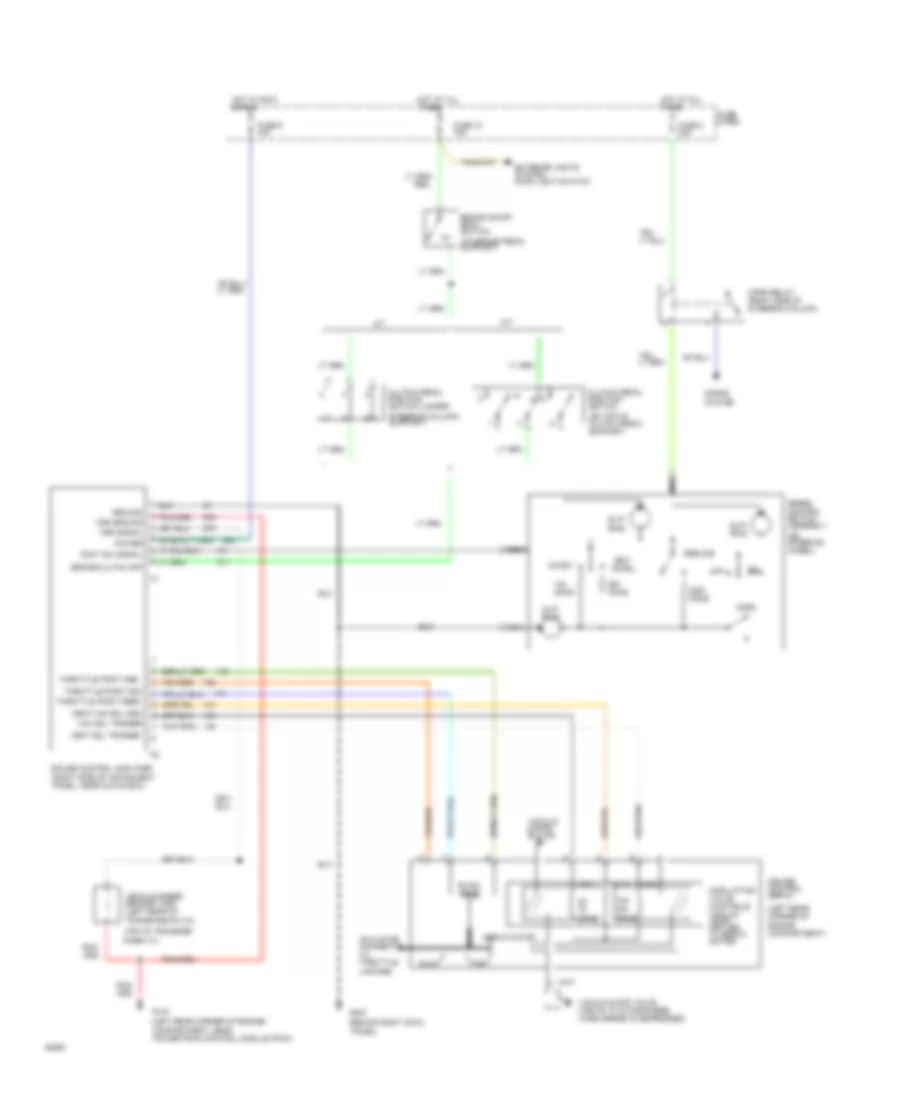
CRUISE CONTROL
Cruise Control Wiring Diagram for Ford Ranger 1994
 https://portal-diagnostov.com/license.html
Automotive Electricians Portal FZCO
Automotive Electricians Portal FZCO
https://portal-diagnostov.com/license.html
https://portal-diagnostov.com/license.html
Automotive Electricians Portal FZCO
Automotive Electricians Portal FZCOList of elements for Cruise Control Wiring Diagram for Ford Ranger 1994:
- (behind right cowl
- (left rear corner of engine compartment)
- (left rear corner of engine
- (on brake pedal support)
- (on steering wheel)
- (on top of clutch pedal support)
- (top of transfer
- 100-
- 40-
- 50,000 ohms
- A/t
- Accel
- Actuator (connects to throttle linkage)
- Brake on/off (boo) switch
- Brake/clutch off
- Case 4*4)
- Clutch pedal position switch
- Clutch pedal position switch jumper
- Coast
- Compartment, near powertrain control module (pcm))
- Cont sw signal
- Cruise control amplifier (right side of instrument panel, near glove box)
- Cruise control servo
- Exterior lights system (main light switch)
- Fast
- Fuse 10 15a
- Fuse 6 10a
- Fuse 8 20a
- Fuse panel
- G104
- G203
- Ground
- Horn
- Horn relay (right side of steering column)
- Horns
- Hot at all times
- Hot in accy or run
- M/t
- Nca
- Off
- Ohms
- Panel)
- Power
- Resume
- Servo motor
- Set/
- Slip ring
- Slow
- Sol+
- Speed control switch assembly
- Steering column) support)
- System
- Throttle posit feed
- Throttle posit gnd
- Throttle posit sig
- Vac
- Vac sol trigger
- Vacuum distri- bution
- Vacuum dump valve (vents to atmosphere when brake is depressed)
- Vehicle speed sensor (vss) (left rear of transmission 4*2)
- Vent
- Vent sol trigger
- Vent/vac sol gnd
- Vss ground
- Vss signal
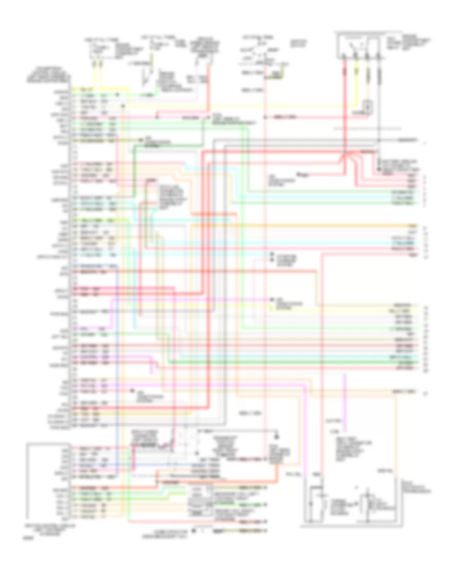
ENGINE PERFORMANCE
2.3L
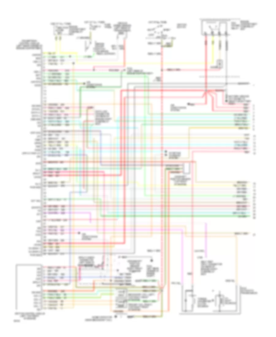
2.3L MFI, Engine Performance Wiring Diagrams (1 of 2) for Ford Ranger 1994
 https://portal-diagnostov.com/license.html
Automotive Electricians Portal FZCO
Automotive Electricians Portal FZCO
https://portal-diagnostov.com/license.html
https://portal-diagnostov.com/license.html
Automotive Electricians Portal FZCO
Automotive Electricians Portal FZCOList of elements for 2.3L MFI, Engine Performance Wiring Diagrams (1 of 2) for Ford Ranger 1994:
- 3-4 shift solenoid
- A4ld automatic transmission
- Acc
- Accs
- Acd
- Air conditioning system
- Boo
- Brake on/off switch (on brake pedal support)
- C198
- C199
- Cid
- Ckp
- Ckp (cid)
- Coil 1
- Coil 2
- Coil 3
- Coil 4
- Cpp m/t-pnp a/t
- Crankshaft position sensor (right front of engine
- Cse gnd
- Data (+)
- Data (-)
- Data link connector (on rear of engine compt fuse/relay box)
- Diode
- Dpfe
- Dpi
- Ect
- Engine compartment fuse/relay box
- Evr
- Fpm
- Fuse 10 15a
- Fuse 4 30a
- Fuse panel
- G104 (left rear of engine compartment)
- G104 left rear corner of engine compt)
- Ho2s
- Ho2s gnd
- Hot at all times
- Iac
- Iat
- Idm
- Ign
- Ign gnd
- Ignition control module (left top front of engine)
- Ignition switch
- Inj bank 1
- Inj bank 2
- Kapwr
- Lock
- Maf
- Maf rtn
- Nca
- Noise capacitor (near secondary coil)
- Oct adj
- Off
- Pcm power relay
- Pip
- Pnk
- Powertrain control module (left rear corner of engine compartment)
- Primary coil (right) (top right front of engine)
- Psp
- Pwr gnd
- Red
- Run
- Secondary coil (left) (top right front of engine)
- Self test input connector (on rear of engine compt fuse/relay box)
- Sig rtn
- Spout
- Spout check connector (left side of engine compt)
- Start
- Starting/ charging system
- Sti
- Sto/mil
- Tan
- Tcc
- Torque converter clutch solenoid
- Vehicle speed sensor (left rear of transmission)
- Vpwr
- Vref
- Vss (+)
- Vss (-)
- Wac
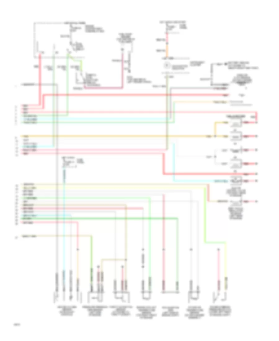
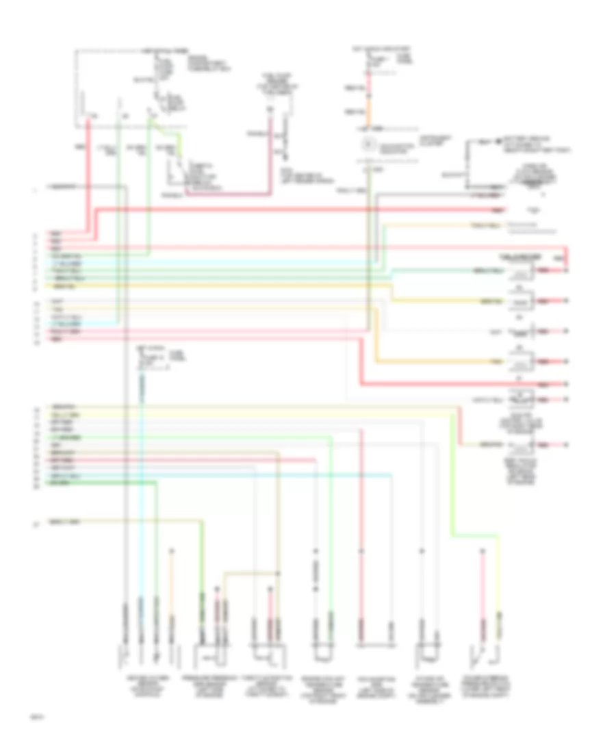
2.3L MFI, Engine Performance Wiring Diagrams (2 of 2) for Ford Ranger 1994
 https://portal-diagnostov.com/license.html
Automotive Electricians Portal FZCO
Automotive Electricians Portal FZCO
https://portal-diagnostov.com/license.html
https://portal-diagnostov.com/license.html
Automotive Electricians Portal FZCO
Automotive Electricians Portal FZCOList of elements for 2.3L MFI, Engine Performance Wiring Diagrams (2 of 2) for Ford Ranger 1994:
- C251
- Egr vacuum regulator solenoid (left rear of engine)
- Engine compartment fuse/relay box
- Engine coolant temperature sensor (top right front of engine)
- Fuel injectors
- Fuel pump relay
- Fuel pump/ sender (top center of fuel tank)
- Fuse 18 15a
- Fuse 22 20a
- Fuse 7 15a
- Fuse panel
- G104 (top center of left fender apron)
- Heated oxygen sensor (on exhaust manifold)
- Hot at all times
- Hot in run
- Hot in run and start
- Idle air control valve (top right rear of engine)
- Inertia fuel shut-off (below glove box)
- Instrument cluster
- Intake air temperature sensor (on air cleaner assembly)
- Malfunction indicator
- Mass air flow sensor (on air cleaner assembly)
- Nca
- Pcm shorting bar (left side of engine compt)
- Power steering pressure switch (lower left front of engine compt)
- Pressure feedback egr sensor (left side of engine)
- Red
- Tan
- Throttle position sensor (attached to throttle body)
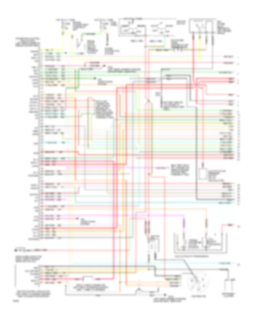
2.3L SFI, Engine Performance Wiring Diagrams (1 of 2) for Ford Ranger 1994
 https://portal-diagnostov.com/license.html
Automotive Electricians Portal FZCO
Automotive Electricians Portal FZCO
https://portal-diagnostov.com/license.html
https://portal-diagnostov.com/license.html
Automotive Electricians Portal FZCO
Automotive Electricians Portal FZCOList of elements for 2.3L SFI, Engine Performance Wiring Diagrams (1 of 2) for Ford Ranger 1994:
- 3-4 shift solenoid
- A4ld automatic transmission
- Acc
- Accs
- Air conditioning system
- Boo
- Brake on/off switch (on brake pedal support)
- C198
- C199
- Camshaft position sensor (top front of engine)
- Cid
- Ckp
- Ckp (cid)
- Coil 1
- Coil 2
- Coil 3
- Coil 4
- Cpp m/t-pnp a/t
- Crankshaft position sensor (right front of engine
- Cse gnd
- Data (+)
- Data (-)
- Data link connector (on rear of engine compt fuse/relay box)
- Diode
- Dpfe
- Dpi
- Ect
- Eec pwr fuse 30a
- Engine compartment fuse/relay box
- Evr
- Fpm
- Fuse 10 15a
- Fuse panel
- G104 (left rear of engine compartment)
- G104 left rear corner of engine compt)
- Ho2s
- Hot at all times
- Iac
- Iat
- Idm
- Ign
- Ign gnd
- Ignition control module (left top front of engine)
- Ignition switch
- Inj 3
- Inj 4
- Inj bank 1
- Inj bank 2
- Kapwr
- Lock
- Maf
- Maf rtn
- Nca
- Noise capacitor (near secondary coil)
- Oct adj
- Off
- Pcm power relay
- Pip
- Pnk
- Powertrain control module (left rear corner of engine compartment)
- Primary coil (right) (top right front of engine)
- Psp
- Pwr gnd
- Red
- Run
- Secondary coil (left) (top right front of engine)
- Self test input connector (on rear of engine compt fuse/relay box)
- Sig rtn
- Spout
- Spout check connector (left side of engine compt)
- Start
- Starting/ charging system
- Sti
- Sto/mil
- Tan
- Tcc
- Torque converter clutch solenoid
- Vehicle speed sensor (left rear of transmission)
- Vpwr
- Vref
- Vss (+)
- Vss (-)
- Wac
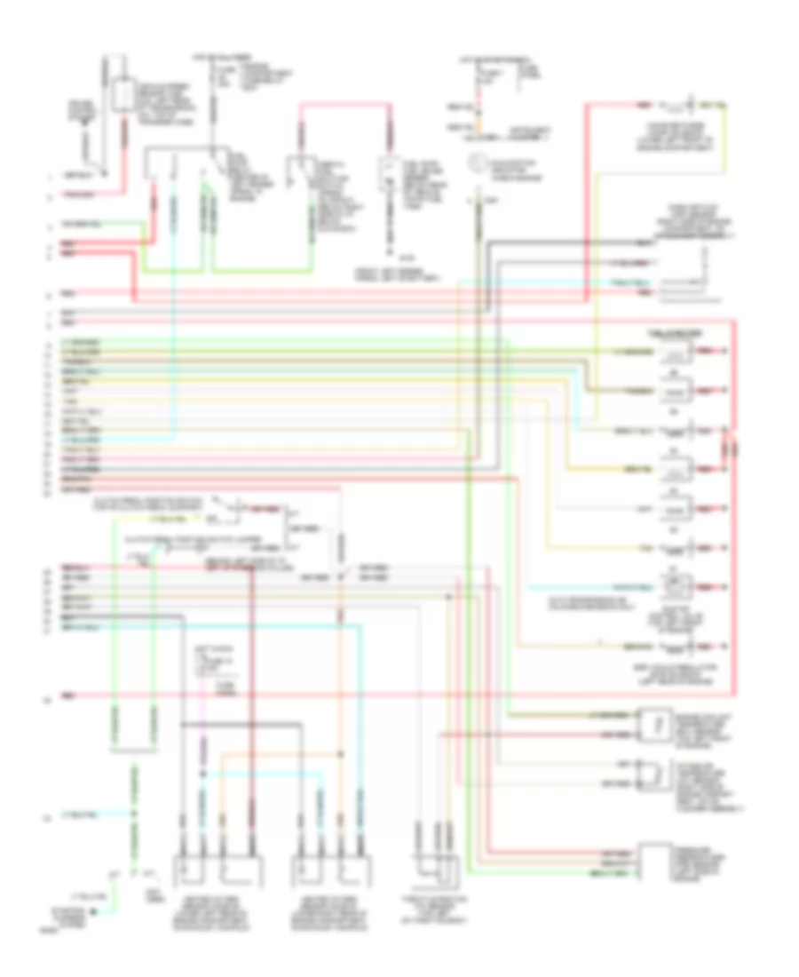
2.3L SFI, Engine Performance Wiring Diagrams (2 of 2) for Ford Ranger 1994
 https://portal-diagnostov.com/license.html
Automotive Electricians Portal FZCO
Automotive Electricians Portal FZCO
https://portal-diagnostov.com/license.html
https://portal-diagnostov.com/license.html
Automotive Electricians Portal FZCO
Automotive Electricians Portal FZCOList of elements for 2.3L SFI, Engine Performance Wiring Diagrams (2 of 2) for Ford Ranger 1994:
- C251
- Egr vacuum regulator solenoid (left rear of engine)
- Engine compartment fuse/relay box
- Engine coolant temperature sensor (top right front of engine)
- Fuel injectors
- Fuel pump relay
- Fuel pump/ sender (top center of fuel tank)
- Fuse 18 15a
- Fuse 7 15a
- Fuse panel
- G104 (top center of left fender apron)
- Heated oxygen sensor (on exhaust manifold)
- Hot at all times
- Hot in run
- Hot in run and start
- Idle air control valve (top right rear of engine)
- Inertia fuel shut-off (below glove box)
- Instrument cluster
- Intake air temperature sensor (on air cleaner assembly)
- Malfunction indicator
- Mass air flow sensor (on air cleaner assembly)
- Nca
- Pcm shorting bar (left side of engine compt)
- Power steering pressure switch (lower left front of engine compt)
- Pressure feedback egr sensor (left side of engine)
- Red
- Tan
- Throttle position sensor (attached to throttle body)
3.0L
3.0L, Engine Performance Wiring Diagrams (1 of 2) for Ford Ranger 1994
 https://portal-diagnostov.com/license.html
Automotive Electricians Portal FZCO
Automotive Electricians Portal FZCO
https://portal-diagnostov.com/license.html
https://portal-diagnostov.com/license.html
Automotive Electricians Portal FZCO
Automotive Electricians Portal FZCOList of elements for 3.0L, Engine Performance Wiring Diagrams (1 of 2) for Ford Ranger 1994:
- (left rear corner of engine compartment, near pcm)
- 4-3 shift solenoid
- A4ld automatic transmission
- Acc
- Accs
- Air conditioning system
- Boo
- Brake on/off switch (behind steering column)
- C250
- Canp
- Clutch cycling pressure switch (on a/c accumulator)
- Coil driver
- Cse gnd
- Data (+)
- Data (-)
- Data link connector (left side of engine com- partment, on rear of engine compartment fuse/relay box)
- Distributor
- Dpfe
- Ect
- Engine compartment fuse/relay box
- Evr
- Fpm
- Fuse 15a
- Fuse 30a
- Fuse panel
- G104
- G104 (left rear corner of engine compartment, near pcm)
- Gnd
- H2os l
- H2os r
- Hot at all times
- Iac
- Iat
- Idm
- Ign gnd
- Ignition coil
- Ignition control module (icm) (left front of engine compart- ment on radiator support)
- Ignition switch
- Inj 1
- Inj 2
- Inj 3
- Inj 4
- Inj 5
- Inj 6
- Instrument cluster
- Kapwr
- Lock
- Maf
- Maf rtn
- Nca
- Off
- Pcm power diode (center of left fender apron)
- Pcm power relay (center of left fender apron)
- Pip
- Pnk
- Pnp
- Power
- Power distribution system
- Powertrain control module (pcm) (left rear corner of engine compartment)
- Pwr gnd
- Radio noise capacitor (right side of engine, near ignition coil)
- Red
- Run
- Self test input (sti) connector (rear of engine compartment fuse/relay box)
- Sig rtn
- Spout
- Spout check connector (left front of engine compart- ment, taped to harness)
- Start
- Sti
- Sto/mil
- Tan
- Tcc
- Torque converter clutch solenoid
- Vpwr
- Vref
- Vss (+)
- Vss (-)
- Wac
3.0L, Engine Performance Wiring Diagrams (2 of 2) for Ford Ranger 1994
 https://portal-diagnostov.com/license.html
Automotive Electricians Portal FZCO
Automotive Electricians Portal FZCO
https://portal-diagnostov.com/license.html
https://portal-diagnostov.com/license.html
Automotive Electricians Portal FZCO
Automotive Electricians Portal FZCOList of elements for 3.0L, Engine Performance Wiring Diagrams (2 of 2) for Ford Ranger 1994:
- (behind left side of i/p, left of steering column)
- (front left fender apron, left of battery)
- (not used)
- A/t
- Auto transmission or california emission only
- C251
- Canister purge (canp) solenoid (lower left front of engine compartment)
- Clutch pedal position switch (top of clutch pedal support)
- Clutch pedal position switch jumper
- Cruise control system
- Egr vacuum regulator (evr) solenoid (left rear of engine)
- Engine compartment fuse/relay box
- Engine coolant temperature (ect) sensor (top left front of engine)
- Fuel injectors
- Fuel pump relay (center of left fender apron, in engine)
- Fuel pump/ fuel gauge sender (below rear of vehicle, top of fuel tank)
- Fuse 18 15a
- Fuse 20a
- Fuse 7 15a
- Fuse panel
- G100
- Heated oxygen sensor (ho2s) #1 (lower right rear of engine compartment, on exhaust manifold)
- Heated oxygen sensor (ho2s) #2 (lower left rear of engine compartment, on exhaust manifold)
- Hot at all times
- Hot in run
- Hot in start or run
- Idle air control valve (top left front of engine)
- Inertia fuel shut-off switch (opens on impact) (below right side of i/p, below glove box)
- Instrument cluster
- Intake air temperature (iat) sensor (right side of engine compart- ment, on air cleaner assembly)
- M/t
- Malfunction indicator "check engine"
- Mass air flow (maf) sensor (right side of engine compartment, on air cleaner assembly)
- Nca
- Pressure feedback egr (pfe) sensor (left side of engine)
- Red
- Starting/ charging system
- Tan
- Throttle position (tp) sensor (top left on throttle body)
- Vehicle speed sensor (vss) (4x2: left rear of transmission, 4x4: top of transfer case)
4.0L
4.0L MFI, Engine Performance Wiring Diagrams (1 of 2) for Ford Ranger 1994
 https://portal-diagnostov.com/license.html
Automotive Electricians Portal FZCO
Automotive Electricians Portal FZCO
https://portal-diagnostov.com/license.html
https://portal-diagnostov.com/license.html
Automotive Electricians Portal FZCO
Automotive Electricians Portal FZCOList of elements for 4.0L MFI, Engine Performance Wiring Diagrams (1 of 2) for Ford Ranger 1994:
- 3-4 shift solenoid
- A4ld automatic transmission
- Acc
- Accs
- Air conditioning system
- Boo
- Brake on/off switch (on brake pedal support)
- C198
- C199
- Canister purge solenoid (lower left front of engine compartment)
- Canp
- Ckp (+)
- Ckp (-)
- Ckp shield gnd
- Coil a
- Coil b
- Coil c
- Cpp m/t-pnp a/t
- Crankshaft position sensor (right front of engine
- Data (+)
- Data (-)
- Data link connector (on rear of engine compt fuse/relay box)
- Diode
- Ect
- Engine compartment fuse/relay box
- Fpm
- Fuse 10 15a
- Fuse 4 30a
- Fuse panel
- G104 (left rear of engine compartment)
- Gnd
- Ho2s-1
- Ho2s-2
- Hot at all times
- Iac
- Iat
- Idm
- Ign gnd
- Ignition coil (top right rear of engine)
- Ignition control module (mounted on upper radiator support)
- Ignition switch
- Inj bank 1
- Inj bank 2
- Kapwr
- Lock
- Maf
- Maf rtn
- Nca
- Oct adj
- Off
- Pcm power relay
- Pcm shorting bar (on engine compt fuse/ relay box)
- Pip
- Pnk
- Power
- Powertrain control module (left rear corner of engine compartment)
- Pwr gnd
- Radio noise capacitor (near ignition coil)
- Red
- Run
- Self test input connector (on rear of engine compt fuse/relay box)
- Sig rtn
- Spout
- Spout check connector (left front corner of engine compt)
- Start
- Starting/ charging system
- Sti
- Sto/mil
- Tan
- Tcc
- Torque converter clutch solenoid
- Vehicle speed sensor (left rear of transmission)
- Vpwr
- Vref
- Vss (+)
- Vss (-)
- Wac
4.0L MFI, Engine Performance Wiring Diagrams (2 of 2) for Ford Ranger 1994
 https://portal-diagnostov.com/license.html
Automotive Electricians Portal FZCO
Automotive Electricians Portal FZCO
https://portal-diagnostov.com/license.html
https://portal-diagnostov.com/license.html
Automotive Electricians Portal FZCO
Automotive Electricians Portal FZCOList of elements for 4.0L MFI, Engine Performance Wiring Diagrams (2 of 2) for Ford Ranger 1994:
- C251
- Engine compartment fuse/relay box
- Engine coolant temperature sensor (top left front of engine)
- Fuel injectors
- Fuel pump relay
- Fuel pump/ sender (at tank in front of rear axle)
- Fuse 18 15a
- Fuse 22 20a
- Fuse 7 15a
- Fuse panel
- G104 (top center of left fender apron)
- Heated oxygen sensor #1 (on exhaust manifold)
- Heated oxygen sensor #2 (on exhaust manifold)
- Hot at all times
- Hot in run
- Hot in run and start
- Idle air control valve (top left rear of engine)
- Inertia fuel shut-off (below glove box)
- Instrument cluster
- Intake air temperature sensor (top left rear of engine)
- Interior fuse panel
- Malfunction indicator
- Mass air flow sensor (on air cleaner assembly)
- Nca
- Red
- Tan
- Throttle position sensor (attached to throttle body)
4.0L SFI, Engine Performance Wiring Diagrams, California (1 of 2) for Ford Ranger 1994
 https://portal-diagnostov.com/license.html
Automotive Electricians Portal FZCO
Automotive Electricians Portal FZCO
https://portal-diagnostov.com/license.html
https://portal-diagnostov.com/license.html
Automotive Electricians Portal FZCO
Automotive Electricians Portal FZCOList of elements for 4.0L SFI, Engine Performance Wiring Diagrams, California (1 of 2) for Ford Ranger 1994:
- 3-4 shift solenoid
- A4ld automatic transmission
- Acc
- Accs
- Air conditioning system
- Boo
- Brake on/off switch (on brake pedal support)
- C198
- C199
- Canister purge solenoid (lower left front of engine compartment)
- Canp
- Ckp (+)
- Ckp (-)
- Ckp shield gnd
- Cmp
- Coil a
- Coil b
- Coil c
- Cpp m/t-pnp a/t
- Crankshaft position sensor (right front of engine
- Cse gnd
- Data (+)
- Data (-)
- Data link connector (on rear of engine compt fuse/relay box)
- Diode
- Dpfe
- Ect
- Engine compartment fuse/relay box
- Evr
- Fpm
- Fuse 10 15a
- Fuse 4 30a
- Fuse panel
- G104 (left rear of engine compartment)
- Ho2s-1
- Ho2s-2
- Hot at all times
- Iac
- Iat
- Idm
- Ign gnd
- Ignition coil (top right rear of engine)
- Ignition control module (mounted on upper radiator support)
- Ignition switch
- Inj 1
- Inj 2
- Inj 3
- Inj 4
- Inj 5
- Inj 6
- Kapwr
- Lock
- Maf
- Maf rtn
- Nca
- Oct adj
- Off
- Pcm power relay
- Pcm shorting bar (on engine compt fuse/ relay box)
- Pip
- Pnk
- Power
- Powertrain control module (left rear corner of engine compartment)
- Pwr gnd
- Radio noise capacitor (near ignition coil)
- Red
- Run
- Self test input connector (on rear of engine compt fuse/relay box)
- Sig rtn
- Spout
- Spout check connector (left front corner of engine compt)
- Start
- Starting/ charging system
- Sti
- Sto/mil
- Tan
- Tcc
- Torque converter clutch solenoid
- Vehicle speed sensor (left rear of transmission)
- Vpwr
- Vref
- Vss (+)
- Vss (-)
- Wac
4.0L SFI, Engine Performance Wiring Diagrams, California (2 of 2) for Ford Ranger 1994
 https://portal-diagnostov.com/license.html
Automotive Electricians Portal FZCO
Automotive Electricians Portal FZCO
https://portal-diagnostov.com/license.html
https://portal-diagnostov.com/license.html
Automotive Electricians Portal FZCO
Automotive Electricians Portal FZCOList of elements for 4.0L SFI, Engine Performance Wiring Diagrams, California (2 of 2) for Ford Ranger 1994:
- C251
- Camshaft position sensor (top rear of engine)
- Egr vacuum regulator solenoid (left rear of engine)
- Engine compartment fuse/relay box
- Engine coolant temperature sensor (top left front of engine)
- Fuel injectors
- Fuel pump relay
- Fuel pump/ sender (at tank in front of rear axle)
- Fuse 18 15a
- Fuse 22 20a
- Fuse 7 15a
- Fuse panel
- G104 (top center of left fender apron)
- Heated oxygen sensor #1 (on exhaust manifold)
- Heated oxygen sensor #2 (on exhaust manifold)
- Hot at all times
- Hot in run
- Hot in run and start
- Idle air control valve (top left rear of engine)
- Inertia fuel shut-off (below glove box)
- Instrument cluster
- Intake air temperature sensor (top left rear of engine)
- Malfunction indicator
- Mass air flow sensor (on air cleaner assembly)
- Nca
- Pressure feedback egr sensor (left side of engine)
- Red
- Tan
- Throttle position sensor (attached to throttle body)
EXTERIOR LIGHTS
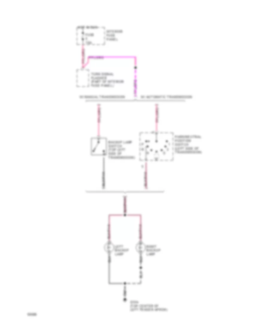
Backup Lamps Wiring Diagram for Ford Ranger 1994
 https://portal-diagnostov.com/license.html
Automotive Electricians Portal FZCO
Automotive Electricians Portal FZCO
https://portal-diagnostov.com/license.html
https://portal-diagnostov.com/license.html
Automotive Electricians Portal FZCO
Automotive Electricians Portal FZCOList of elements for Backup Lamps Wiring Diagram for Ford Ranger 1994:
- Backup lamp switch (top left side of transmission)
- Fuse 15a
- G104 (top center of left fender apron)
- Hot in run
- Interior fuse panel
- Left backup lamp
- Park/neutral position switch (left side of transmission)
- Right backup lamp
- Turn signal flasher (part of interior fuse panel)
- W/ automatic transmission
- W/ manual transmission
Exterior Lamps Wiring Diagram for Ford Ranger 1994
 https://portal-diagnostov.com/license.html
Automotive Electricians Portal FZCO
Automotive Electricians Portal FZCO
https://portal-diagnostov.com/license.html
https://portal-diagnostov.com/license.html
Automotive Electricians Portal FZCO
Automotive Electricians Portal FZCOList of elements for Exterior Lamps Wiring Diagram for Ford Ranger 1994:
- Aniti-lock brake system (rear anti-lock brake module pin #12)
- Brake input
- Brake on/off signal
- Brake on/off switch (on brake pedal bracket)
- C250
- C251
- C279
- C286
- C289
- C293
- Clutch pedal position switch (top of clutch pedal support)
- Clutch pedal position switch jumper (left of steering column)
- Fuse 15a
- G100 (front left fender apron, near battery)
- G104 (top center of left fender apron)
- G200 (behind left cowl panel)
- Hazard
- Hazard flasher (part of interior fuse panel)
- Head
- Headlamp switch
- High mount stop lamp
- Hot at all times
- Hot in run
- Instrument cluster
- Interior fuse panel
- Lamps on input
- Left front park/ turn lamp
- Left rear park/ stop lamp
- Left rear turn lamp
- Left turn indicator
- License lamp
- License lamps
- Multi-function switch (left side of steering column)
- Normal
- Off
- Outside cargo/ high mount stop lamps
- Park
- Power distribution system
- Powertrain control module (left rear corner of engine compartment)
- Rear anti- lock brake module (left side of ashtray assembly)
- Red
- Regualr cab w/ short wheelbase
- Right front park/ turn lamp
- Right rear park/ stop lamp
- Right rear turn lamp
- Right turn indicator
- Supercab & regular cab w/ long wheelbase
- Turn left
- Turn right
- Turn signal flasher (part of interior fuse panel)
- W/ automatic transmission
- W/ manual transmission
- W/ rear bumper
- W/o rear bumper
- Warning chime module (below ashtray assembly)
GROUND DISTRIBUTION
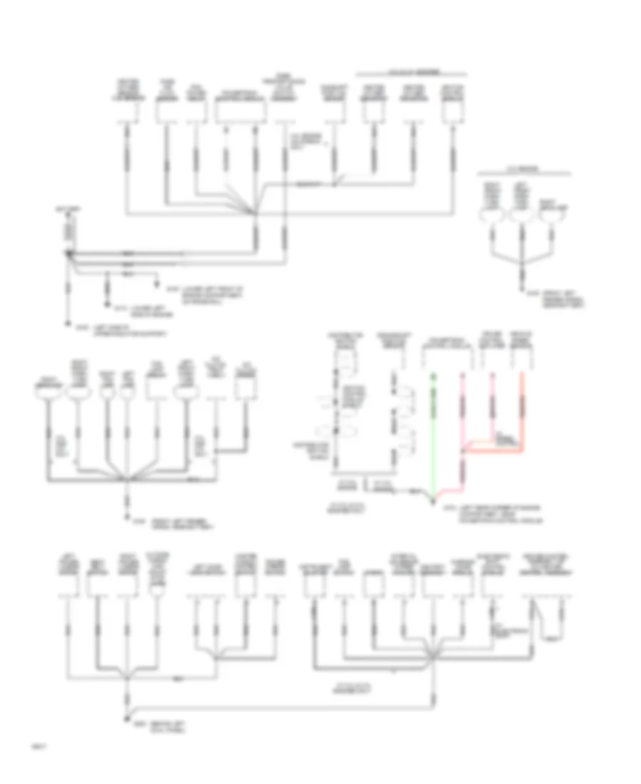
Ground Distribution Wiring Diagram (1 of 2) for Ford Ranger 1994
 https://portal-diagnostov.com/license.html
Automotive Electricians Portal FZCO
Automotive Electricians Portal FZCO
https://portal-diagnostov.com/license.html
https://portal-diagnostov.com/license.html
Automotive Electricians Portal FZCO
Automotive Electricians Portal FZCOList of elements for Ground Distribution Wiring Diagram (1 of 2) for Ford Ranger 1994:
- (behind left cowl panel)
- (front left fender apron, near battery)
- (left rear corner of engine compartment, near
- (left side of upper radiator support)
- (lower left side of engine)
- (lower left front of engine compartment, on frame rail)
- 2.3l engine
- 3.0l & 4.0l engines
- 3.0l and 4.0l only
- 4.0l engine california only
- A/c clutch diode
- A/c clutch field coil
- Ashtray assembly
- Battery
- C206
- C214
- C215
- C250
- Camshaft position sensor
- Crankshaft position sensor
- Cruise control amplifier
- Distributor ignition shield
- Electronic shift control module
- Fog lamp relay
- Fog lamp switch
- G100
- G104
- G108
- G112
- G200
- Heated oxygen sensor #1
- Heated oxygen sensor #2
- Heated oxygen sensor (2.3l engine)
- Heater control assembly or a/c heater control assembly
- Ignition control module
- Ignition control module shield
- Instrument cluster
- Interval governor (wiper/ washer)
- Left door lock switch
- Left fog lamp
- Left front park/ turn lamp
- Left power lumbar motor
- Mass air flow sensor
- Master window control switch
- Outside cargo/ high mount stop lamps
- Pcm power relay
- Power mirror switch
- Powertrain control module
- Powertrain control module)
- Rabs proportioning valve switch assembly
- Radio
- Right fog lamp
- Right front park/ turn lamp
- Right headlamp
- Right power lumbar motor
- Seat belt switch
- Vehicle speed sensor
- W/ 2.3l & 3.0l engines only
- W/ 2.3l engine
- W/ 3.0l & 4.0l engines only
- W/ 3.0l engine
- W/ speed control
- Warning chime module
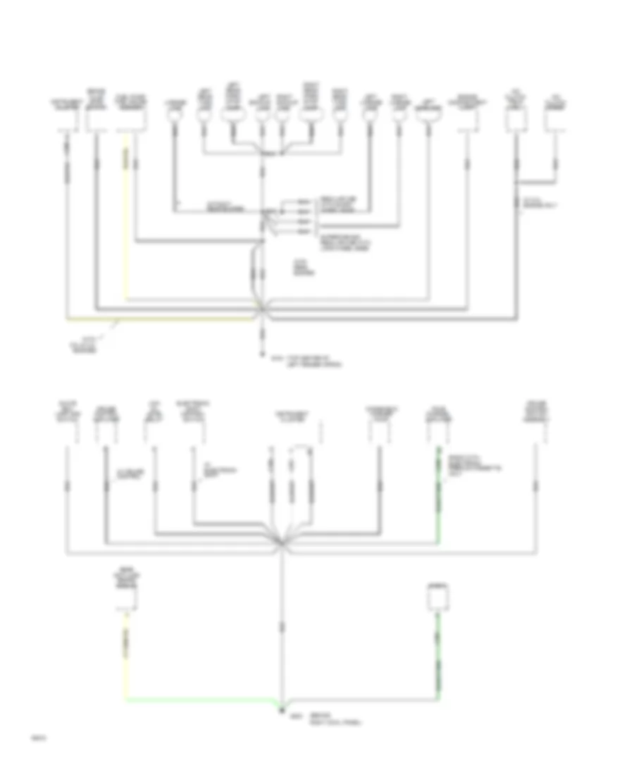
Ground Distribution Wiring Diagram (2 of 2) for Ford Ranger 1994
 https://portal-diagnostov.com/license.html
Automotive Electricians Portal FZCO
Automotive Electricians Portal FZCO
https://portal-diagnostov.com/license.html
https://portal-diagnostov.com/license.html
Automotive Electricians Portal FZCO
Automotive Electricians Portal FZCOList of elements for Ground Distribution Wiring Diagram (2 of 2) for Ford Ranger 1994:
- (behind
- (top center of left fender apron)
- A/c clutch diode
- A/c clutch field coil
- Brake fluid level switch
- C250
- C251
- C257
- C298
- Cruise control amplifier
- Cruise control switch assembly
- Electronic shift control switch
- Engine compartment lamp
- Four channel amplifier
- Fuel pump/ fuel gauge sender
- G104
- G203
- Glove box lamp and switch
- Instrument cluster
- Left backup lamp
- Left headlamp
- Left license lamp
- Left rear park/ stop lamp
- Left rear turn lamp
- License lamp
- Low oil level relay
- Radio
- Radio with electronic premium cassette only
- Rear anti-lock brake module
- Regular cab with short wheel base
- Right backup lamp
- Right cowl panel)
- Right license lamp
- Right rear park/ stop lamp
- Right rear turn lamp
- Supercab and regular cab with long wheel base
- W/ 2.3l engine only
- W/ cruise control
- W/ electronic shift
- Windshield washer pump
- With 3.0l & 4.0l engines
- With rear bumper
- Without rear bumper
HEADLIGHTS
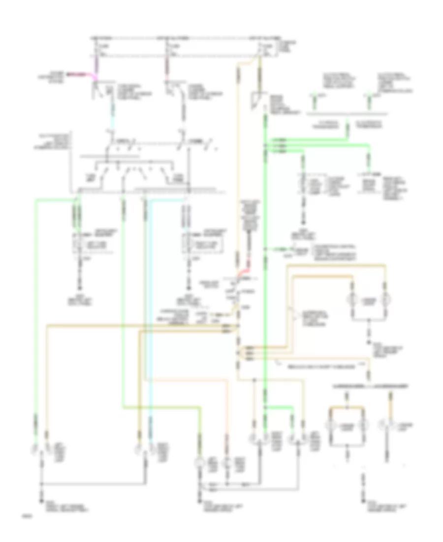
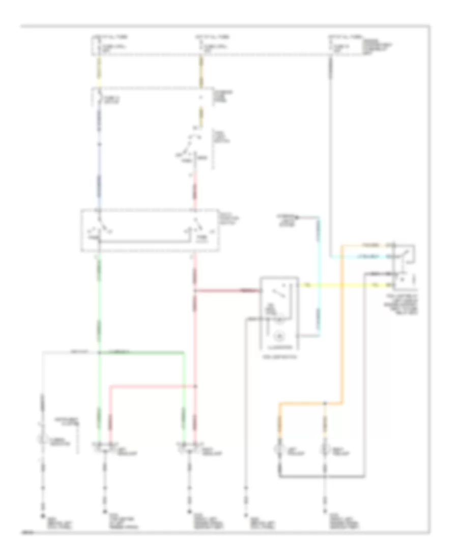
Headlamps Wiring Diagram for Ford Ranger 1994
 https://portal-diagnostov.com/license.html
Automotive Electricians Portal FZCO
Automotive Electricians Portal FZCO
https://portal-diagnostov.com/license.html
https://portal-diagnostov.com/license.html
Automotive Electricians Portal FZCO
Automotive Electricians Portal FZCOList of elements for Headlamps Wiring Diagram for Ford Ranger 1994:
- 'on' indic- ator
- Cluster
- Engine compartment fuse/relay box
- Fog lamp relay (left side of engine compart- ment, in fuse/ relay box)
- Fog lamp switch
- Fuse 12 20a c.b.
- Fuse 19 20a
- Fuse 2 (pnl) 40a
- Fuse 3 (pnl) 60a
- G100 (front left fender apron, near battery)
- G104 (top center of left fender apron)
- G200 (behind left cowl panel)
- Head
- Hi beam indicator
- Hot at all times
- Illumination
- Instrument
- Interior
- Interior fuse panel
- Left foglamp
- Left headlamp
- Lights system
- Main light switch
- Multi- function switch
- Off
- Park
- Pass
- Right foglamp
- Right headlamp
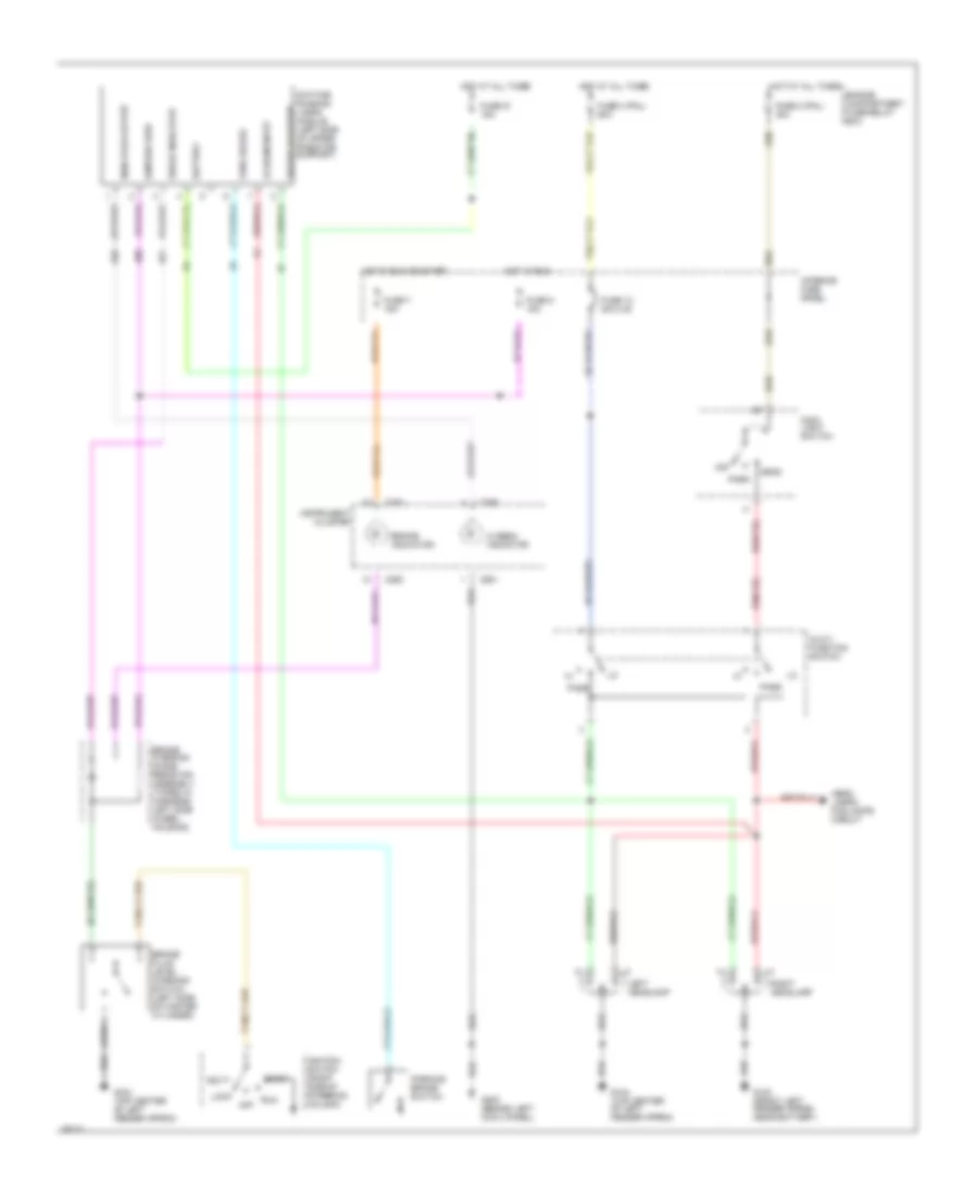
Headlamps Wiring Diagram, with DRL for Ford Ranger 1994
 https://portal-diagnostov.com/license.html
Automotive Electricians Portal FZCO
Automotive Electricians Portal FZCO
https://portal-diagnostov.com/license.html
https://portal-diagnostov.com/license.html
Automotive Electricians Portal FZCO
Automotive Electricians Portal FZCOList of elements for Headlamps Wiring Diagram, with DRL for Ford Ranger 1994:
- Acc
- Battery
- Brake fluid level warning switch (left side of master cylinder)
- Brake indicator
- Brake warning diode/ resistor assembly (taped in harness, left side wheel housing)
- C250
- C251
- Cluster
- Daytime running lamps module (left side of upper radiator support)
- Engine compartment fuse/relay box
- Fuse 12 20a c.b.
- Fuse 2 (pnl) 40a
- Fuse 21 15a
- Fuse 3 (pnl) 60a
- Fuse 5 15a
- Fuse 7 15a
- G100 (front left fender apron, near battery)
- G104 (top center of left fender apron)
- G200 (behind left cowl panel)
- Head
- Head- lamps/ fog lamps circuit
- Hi beam indicator
- Hot at all times
- Hot in run
- Hot in run or start
- Ignition feed
- Ignition switch (right side of steering column)
- Indicator output
- Instrument
- Interior fuse panel
- Left headlamp
- Lo beam input
- Lock
- Main light switch
- Multi- function switch
- Off
- Park
- Park brake
- Parking brake switch
- Pass
- Pulsed hi output
- Right headlamp
- Run
- Start
HORN
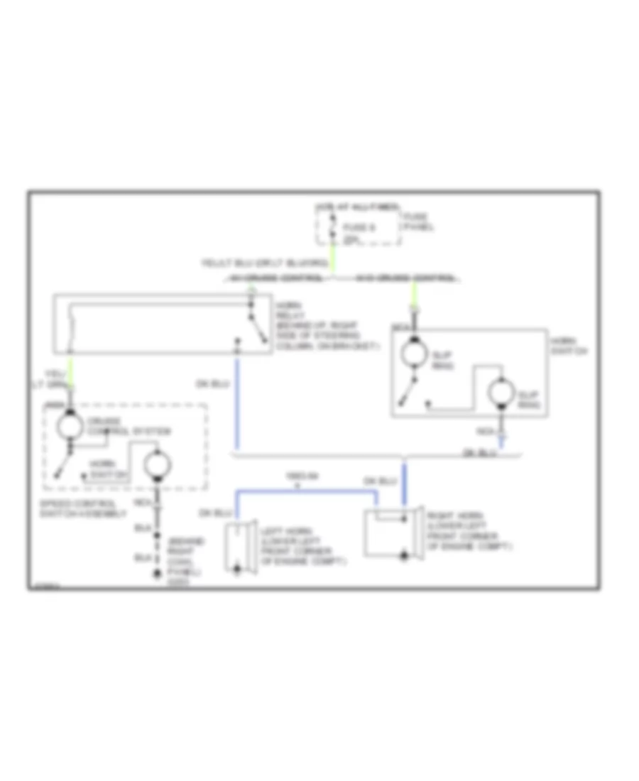
Horn Wiring Diagram for Ford Ranger 1994
 https://portal-diagnostov.com/license.html
Automotive Electricians Portal FZCO
Automotive Electricians Portal FZCO
https://portal-diagnostov.com/license.html
https://portal-diagnostov.com/license.html
Automotive Electricians Portal FZCO
Automotive Electricians Portal FZCOList of elements for Horn Wiring Diagram for Ford Ranger 1994:
- (behind right cowl panel) g203
- 1993-94
- 20a
- Cruise control system
- Fuse 8
- Fuse panel
- Horn relay (behind i/p, right side of steering column, on bracket)
- Horn switch
- Hot at all times
- Left horn (lower left front corner of engine compt)
- Nca
- Right horn (lower left front corner of engine compt)
- Slip ring
- Speed control switch assembly
- W/ cruise control
- W/o cruise control
INSTRUMENT CLUSTER
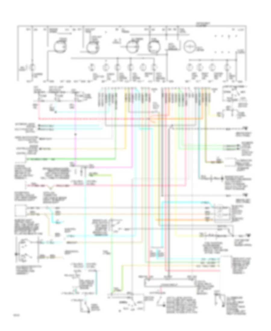
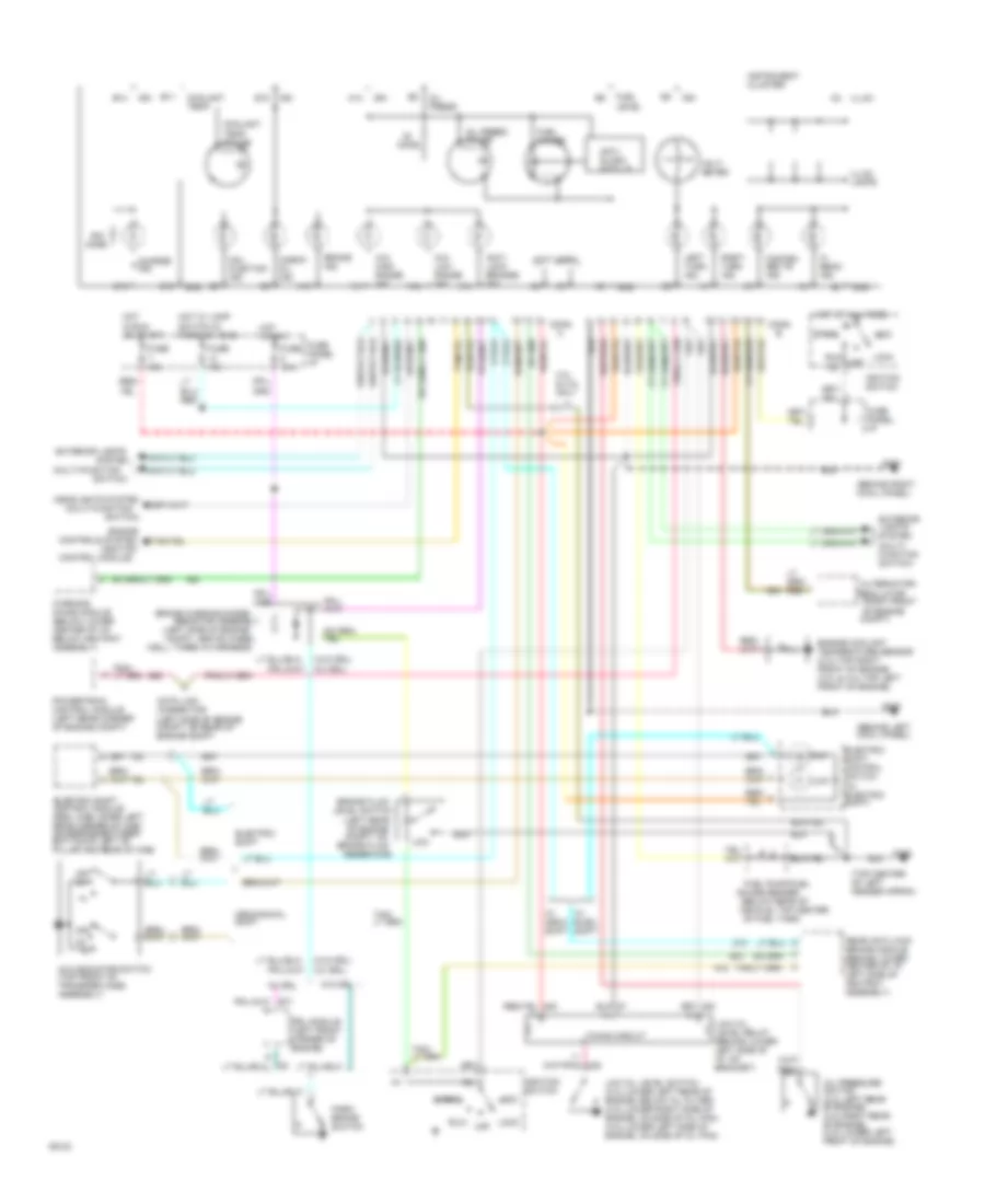
Instrument Cluster Wiring Diagram, Sport for Ford Ranger 1994
 https://portal-diagnostov.com/license.html
Automotive Electricians Portal FZCO
Automotive Electricians Portal FZCO
https://portal-diagnostov.com/license.html
https://portal-diagnostov.com/license.html
Automotive Electricians Portal FZCO
Automotive Electricians Portal FZCOList of elements for Instrument Cluster Wiring Diagram, Sport for Ford Ranger 1994:
- (behind left cowl panel)
- (behind right cowl panel)
- (below rear of
- (ignition
- (left rear of engine compt, on
- (left side of engine compt, above wheel
- (left side of engine compt, on rear of engine compt
- (multi-function
- (right front
- (top center of left fender apron)
- (w/ drl)
- (w/o drl)
- 3.0l & 4.0l only
- 4x4
- 4x4 high range ind.
- 4x4 indicator switch (top front of transfer case assembly)
- 4x4 low range ind.
- A10
- A11
- A12
- A13
- A14
- Acc
- Alternator/
- Anti- lock brakes ind.
- Anti- slosh module
- B10
- B11
- B12
- B13
- B14
- Brake fluid
- Brake ind.
- Brake warning diode/
- Charge ind.
- Check oil ind.
- Compt)
- Conn
- Control module)
- Controls system
- Coolant temp.
- Coolant temp. gauge
- Data link connector
- Drl module (left front corner of engine)
- Electric shift
- Electric shift control module (reg. cab-lower left rear corner of cab) (supercab-between bottom of left "b" pillar and rear of cab)
- Electric shift control switch (w/ electric shift)
- Engine
- Engine coolant temperature sensor (2.3l-top right front of engine) (3.0l & 4.0l-top left front of engine)
- Engine speed
- Exterior lights
- Exterior lights system (multi- function switch)
- Fasten belts ind.
- Fuel gauge
- Fuel level
- Fuel pump/fuel
- Fuse 10a
- Fuse 15a
- Fuse panel: i/p
- G104
- G200
- G203
- Gauge sender
- Gnd
- Headlights system
- Hi beam ind.
- Hot at all times
- Hot in run
- Hot in run or start
- Hot w/ lamp switch in park or head
- Ign
- Ignition switch
- Illum.
- Illum. lamps
- Instrument cluster
- Left turn ind.
- Level switch
- Lock
- Low
- Low oil level relay (behind lower left side of i/p, on bracket)
- Low oil level switch (2.3l-lower left rear of engine, below oil filter) (3.0l-lower right side of engine, on side of oil pan) (4.0l-lower left side of engine, on side of oil pan)
- Mal- function ind.
- Mechanical shift
- Of engine
- Of fuel tank)
- Off
- Off 4h
- Ohms
- Oil press.
- Oil press. gauge
- Oil pressure switch (2.3l-left rear of engine) (3.0l-right rear of engine) (4.0l-lower left front of engine)
- Park brake switch
- Powertrain control module (left rear corner of engine compt)
- Rear anti-lock brake module (behind lower center of i/p, left side of ashtray assembly)
- Regulator
- Reservoir)
- Resistor assembly
- Right turn ind.
- Run
- Start
- Switch)
- System
- Tacho- meter
- Timing circuit
- Vehicle, top center
- Volt- meter
- W/ drl
- W/ elec. shift
- W/ mech. shift
- W/o drl
- Warning chime module (below lower center of i/p, below ashtray assembly)
- Well, taped in harness)
Instrument Cluster Wiring Diagram, Standard for Ford Ranger 1994
 https://portal-diagnostov.com/license.html
Automotive Electricians Portal FZCO
Automotive Electricians Portal FZCO
https://portal-diagnostov.com/license.html
https://portal-diagnostov.com/license.html
Automotive Electricians Portal FZCO
Automotive Electricians Portal FZCOList of elements for Instrument Cluster Wiring Diagram, Standard for Ford Ranger 1994:
- (behind left cowl panel)
- (behind right cowl panel)
- (below rear of
- (ignition
- (left rear of engine compt, on
- (left side of engine compt, above wheel
- (left side of engine compt, on rear of engine compt
- (multi-function
- (not used)
- (right front
- (top center of left fender apron)
- (w/ drl)
- (w/o drl)
- 3.0l & 4.0l only
- 4x4
- 4x4 high range ind.
- 4x4 indicator switch (top front of transfer case assembly)
- 4x4 low range ind.
- A10
- A11
- A12
- A13
- A14
- Acc
- Alternator/
- Anti- lock brakes ind.
- Anti- slosh module
- B10
- B11
- B12
- B13
- B14
- Brake fluid
- Brake ind.
- Brake warning diode/
- Charge ind.
- Check oil ind.
- Compt)
- Conn
- Control module)
- Controls system
- Coolant temp.
- Coolant temp. gauge
- Data link connector
- Drl module (left front corner of engine)
- Electric shift
- Electric shift control module (reg. cab-lower left rear corner of cab) (supercab-between bottom of left "b" pillar and rear of cab)
- Electric shift control switch (w/ electric shift)
- Engine
- Engine coolant temperature sensor (2.3l-top right front of engine) (3.0l & 4.0l-top left front of engine)
- Exterior lights
- Exterior lights system (multi- function switch)
- Fasten belts ind.
- Fuel gauge
- Fuel level
- Fuel pump/fuel
- Fuse 10a
- Fuse 15a
- Fuse panel: i/p
- G104
- G200
- G203
- Gauge sender
- Gnd
- Headlights system
- Hi beam ind.
- Hot at all times
- Hot in run
- Hot in run or start
- Hot w/ lamp switch in park or head
- Ign
- Ignition switch
- Illum.
- Illum. lamps
- Instrument cluster
- Left turn ind.
- Level switch
- Lock
- Low
- Low oil level relay (behind lower left side of i/p, on bracket)
- Low oil level switch (2.3l-lower left rear of engine, below oil filter) (3.0l-lower right side of engine, on side of oil pan) (4.0l-lower left side of engine, on side of oil pan)
- Mal- function ind.
- Mechanical shift
- Of engine
- Of fuel tank)
- Off
- Off 4h
- Ohms
- Oil press.
- Oil press. gauge
- Oil pressure switch (2.3l-left rear of engine) (3.0l-right rear of engine) (4.0l-lower left front of engine)
- Park brake switch
- Powertrain control module (left rear corner of engine compt)
- Rear anti-lock brake module (behind lower center of i/p, left side of ashtray assembly)
- Regulator
- Reservoir)
- Resistor assembly
- Right turn ind.
- Run
- Start
- Switch)
- System
- Timing circuit
- Vehicle, top center
- Volt- meter
- W/ drl
- W/ elec. shift
- W/ mech. shift
- W/o drl
- Warning chime module (below lower center of i/p, below ashtray assembly)
- Well, taped in harness)
INTERIOR LIGHTS
Courtesy Lamps Wiring Diagram for Ford Ranger 1994
 https://portal-diagnostov.com/license.html
Automotive Electricians Portal FZCO
Automotive Electricians Portal FZCO
https://portal-diagnostov.com/license.html
https://portal-diagnostov.com/license.html
Automotive Electricians Portal FZCO
Automotive Electricians Portal FZCOList of elements for Courtesy Lamps Wiring Diagram for Ford Ranger 1994:
- C293
- Dome
- Dome lamp
- Door ajar input
- Engine compartment fuse/relay box
- Engine compartment lamp
- Fuse 15a
- Fuse panel
- G104 (top center of left fender apron)
- G200 (behind left cowl panel)
- G203 (behind right cowl panel)
- Glove box lamp & switch
- Headlights system (daytime running lamps module pin #4)
- Hot at all times
- Left courtesy lamp switch (in door jamb)
- Main light switch
- Map lamp
- Mirror system (power mirror switch pin #7)
- Outside cargo lamp
- Outside cargo/ hight mount stop lamps
- Red/ pnk
- Regular cab
- Right courtesy lamp switch (in door jamb)
- Sound system (radio pin #1/c257)
- Supercab
- Warning chime module (below ashtray assembly)
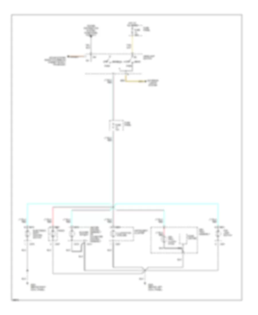
Instrument Illumination Wiring Diagram for Ford Ranger 1994
 https://portal-diagnostov.com/license.html
Automotive Electricians Portal FZCO
Automotive Electricians Portal FZCO
https://portal-diagnostov.com/license.html
https://portal-diagnostov.com/license.html
Automotive Electricians Portal FZCO
Automotive Electricians Portal FZCOList of elements for Instrument Illumination Wiring Diagram for Ford Ranger 1994:
- Ash tray assembly
- Ash tray illumin- ation
- Blower switch
- C201
- C214
- C215
- C250
- C251
- C257
- C278
- Cigar lighter
- Electronic shift control switch
- Exterior lights system
- Fog lamp switch
- Fuse 10a
- Fuse 15a
- Fuse panel
- G200 (behind left cowl panel)
- G203 (behind right cowl panel)
- Head
- Headlamp switch
- Heater control assembly or a/c-heater control assembly
- Hot at all times
- Ign
- Illumination (5 bulbs)
- Instrument cluster
- Off
- Park
- Power distribution system (fuse panel fuse #11)
- Radio
- Sound system (radio w/o premium cassette only pin #5/c257)
POWER DISTRIBUTION
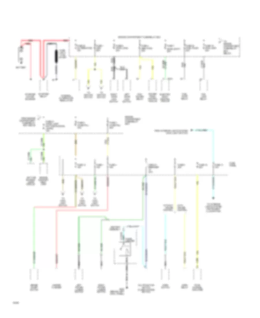
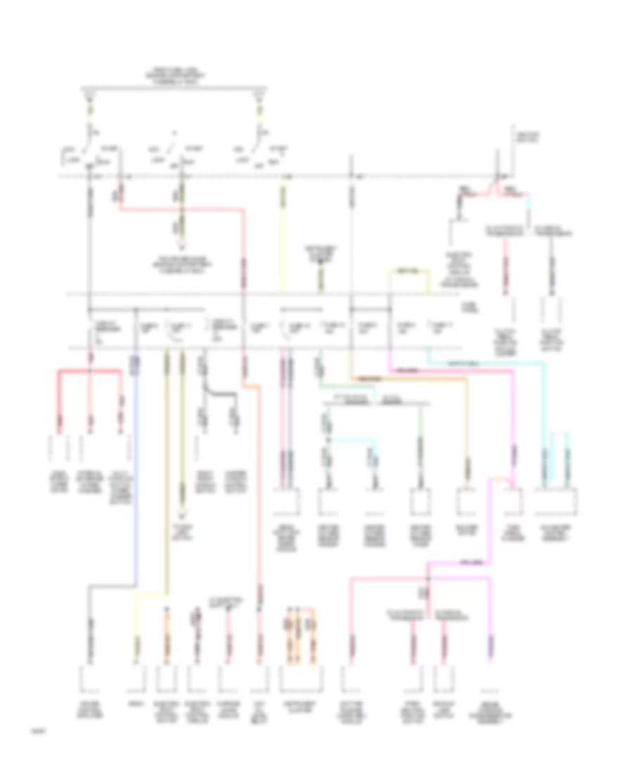
Power Distribution Wiring Diagram (1 of 3) for Ford Ranger 1994
 https://portal-diagnostov.com/license.html
Automotive Electricians Portal FZCO
Automotive Electricians Portal FZCO
https://portal-diagnostov.com/license.html
https://portal-diagnostov.com/license.html
Automotive Electricians Portal FZCO
Automotive Electricians Portal FZCOList of elements for Power Distribution Wiring Diagram (1 of 3) for Ford Ranger 1994:
- (elec shift) 20a
- Ashtray assembly
- Battery
- Brake on/off switch
- C204
- C298
- Cigar lighter
- Circuit breaker 20a
- Compartment fuse/relay box above
- Daytime
- Electric shift control module
- Engine compart- ment lamp
- Engine compartment fuse/relay box
- Fog lamp relay
- Four- channel amplifier
- From engine a
- From interior lights system (main light switch)
- Fuel pump relay
- Fuse 1 (ign) 60a
- Fuse 1 15a
- Fuse 10 15a
- Fuse 13 10a
- Fuse 16 20a
- Fuse 19 (fog lamp) 20a
- Fuse 2 (fuse pnl) 40a
- Fuse 20 (alternator) 15a
- Fuse 21 (hood lamp/ daytime running lamps) 15a
- Fuse 22 (fuel pump) 20a
- Fuse 3 (fuse pnl) 60a
- Fuse 4 (eec pwr) 30a
- Fuse 4 15a
- Fuse 6 (pwr lcks) 20a
- Fuse 7
- Fuse 8 20a
- Fuse panel
- G200 (behind left cowl panel)
- Hazard flasher
- Horn relay
- Horn switch
- Integral alternator regulator
- Left door lock switch
- Left power lumbar switch
- Multifunction switch (flash-to-pass switch)
- Nca
- Pcm power relay
- Power- train control module
- Red
- Right door lock switch
- Right power lumbar switch
- Running lamps module
- Starter motor/ solenoid
- Starter relay
- To engine compartment fuse/relay box below
- To ignition switch
- To interior lights system (instrument illumination)
- To main light switch
- With cruise control
- Without cruise control
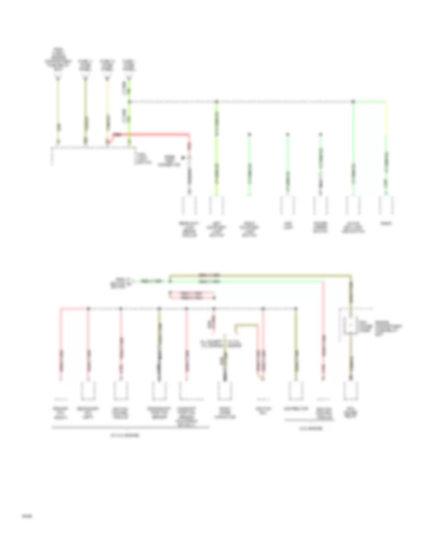
Power Distribution Wiring Diagram (2 of 3) for Ford Ranger 1994
 https://portal-diagnostov.com/license.html
Automotive Electricians Portal FZCO
Automotive Electricians Portal FZCO
https://portal-diagnostov.com/license.html
https://portal-diagnostov.com/license.html
Automotive Electricians Portal FZCO
Automotive Electricians Portal FZCOList of elements for Power Distribution Wiring Diagram (2 of 3) for Ford Ranger 1994:
- (w/ manual transmission)
- A/c-heater control assembly
- Acc
- Backup lamp switch
- Blower motor
- Brake warning diode/resistor assembly
- C204
- C205
- C250
- C251
- C270
- Circuit breaker
- Circuit breaker 30a
- Clutch pedal position switch
- Clutch pedal position switch jumper
- Cruise control amplifier
- Daytime running lamps (drl) module
- Electric shift control module
- Electric shift control switch
- From fuse 1 (ign) (engine compartment
- Fuse 11 15a
- Fuse 15 20a
- Fuse 17 10a
- Fuse 18 15a
- Fuse 5 15a
- Fuse 6 10a
- Fuse 7 15a
- Fuse 9 30a
- Fuse panel
- Fuse/relay box)
- Heated oxygen sensor (ho2s)
- Heated oxygen sensor (ho2s)#1
- Heated oxygen sensor (ho2s)#2
- Ignition switch
- Instrument cluster
- Instrument cluster system
- Interval governor (wiper/ washer)
- Lock
- Low oil level relay
- Master window control switch
- Multi- function switch (wiper/ washer switch)
- Nca
- Off
- Park/ neutral position switch
- Pcm power diode (engine compartment
- Radio
- Rear anti-lock brake (rabs) module
- Red
- Right front window switch
- Run
- Start
- To main light switch
- Turn signal flasher
- W/ 2.3l engine
- W/ 3.0l & 4.0l engines
- W/ automatic transmision
- W/ automatic transmission
- W/ electric shift only
- W/ manual transmision
- W/ manual transmission
- Warning chime module
- Wind- shield wiper motor
Power Distribution Wiring Diagram (3 of 3) for Ford Ranger 1994
 https://portal-diagnostov.com/license.html
Automotive Electricians Portal FZCO
Automotive Electricians Portal FZCO
https://portal-diagnostov.com/license.html
https://portal-diagnostov.com/license.html
Automotive Electricians Portal FZCO
Automotive Electricians Portal FZCOList of elements for Power Distribution Wiring Diagram (3 of 3) for Ford Ranger 1994:
- (3.0l engine)
- (right)
- (w/ 2.3l engine)
- All except 3.0l engine
- C155
- C169
- C257
- Camshaft position sensor (california sfi only)
- Connector
- Crankshaft position sensor
- Distributor
- Engine compartment fuse/relay box
- From fuse 2 (engine compartment fuse relay box)
- From ignition h switch
- Fuse 1 (fuse panel)
- Fuse 10 (fuse panel)
- Fuse 11 (fuse panel)
- Glove box lamp and switch
- Ign
- Ignition coil
- Ignition control module
- Left courtesy lamp switch
- Main light switch
- Map lamp
- Nca
- Pcm power diode
- Pcm power relay
- Power mirror switch
- Primary coil
- Rabs test
- Radio
- Radio noise capacitor
- Rear anti- lock brake module
- Red
- Right courtesy lamp switch
- Secondary coil (left)
- W/ 3.0l engine
POWER DOOR LOCKS
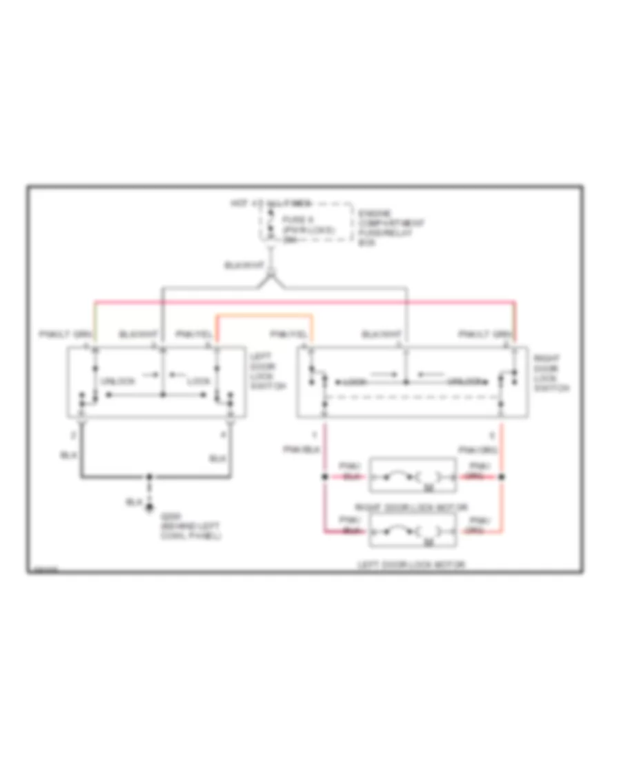
Power Door Lock Wiring Diagram for Ford Ranger 1994
 https://portal-diagnostov.com/license.html
Automotive Electricians Portal FZCO
Automotive Electricians Portal FZCO
https://portal-diagnostov.com/license.html
https://portal-diagnostov.com/license.html
Automotive Electricians Portal FZCO
Automotive Electricians Portal FZCOList of elements for Power Door Lock Wiring Diagram for Ford Ranger 1994:
- Engine compartment fuse/relay box
- Fuse 6 (pwr lcks) 20a
- G200 (behind left cowl panel)
- Hot at all times
- Left door lock motor
- Left door lock switch
- Lock
- Pnk/
- Right door lock motor
- Right door lock switch
- Unlock
POWER MIRRORS
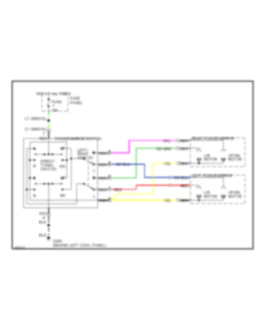
Power Mirror Wiring Diagram for Ford Ranger 1994
 https://portal-diagnostov.com/license.html
Automotive Electricians Portal FZCO
Automotive Electricians Portal FZCO
https://portal-diagnostov.com/license.html
https://portal-diagnostov.com/license.html
Automotive Electricians Portal FZCO
Automotive Electricians Portal FZCOList of elements for Power Mirror Wiring Diagram for Ford Ranger 1994:
- Direct- tional switch
- Fuse 15a
- Fuse panel
- G200 (behind left cowl panel)
- Hot at all times
- L/r motor
- Left/ right switch
- Nca
- Power mirror switch
- Red
- Right power mirror nca
- Up/dn motor
POWER SEATS
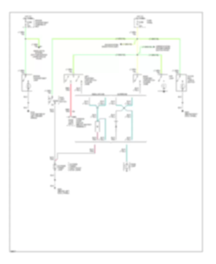
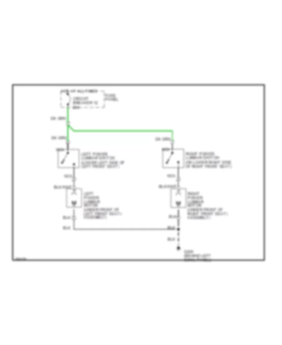
Lumbar Wiring Diagram for Ford Ranger 1994
 https://portal-diagnostov.com/license.html
Automotive Electricians Portal FZCO
Automotive Electricians Portal FZCO
https://portal-diagnostov.com/license.html
https://portal-diagnostov.com/license.html
Automotive Electricians Portal FZCO
Automotive Electricians Portal FZCOList of elements for Lumbar Wiring Diagram for Ford Ranger 1994:
- Circuit breaker 12 20a
- Fuse panel
- G200 (behind left cowl panel)
- Hot at all times
- Left power lumbar motor (under front of left front seat) assembly)
- Left power lumbar switch (lower left side of left front seat)
- Nca
- Right power lumbar motor (under front of right front seat) assembly)
- Right power lumbar switch (on lower right side of right front seat)
POWER WINDOWS
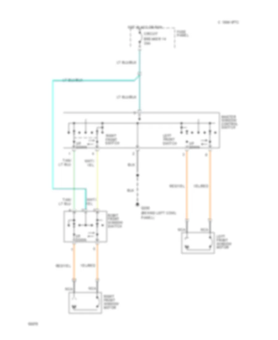
Power Window Wiring Diagram for Ford Ranger 1994
 https://portal-diagnostov.com/license.html
Automotive Electricians Portal FZCO
Automotive Electricians Portal FZCO
https://portal-diagnostov.com/license.html
https://portal-diagnostov.com/license.html
Automotive Electricians Portal FZCO
Automotive Electricians Portal FZCOList of elements for Power Window Wiring Diagram for Ford Ranger 1994:
- (behind left cowl
- 1994 vftc c
- 30a
- Breaker 14
- Circuit
- Front switch
- Fuse panel
- G200
- Hot in acc or run
- Left
- Left front window motor
- Master window control switch
- Nca
- Panel)
- Right front window motor
- Right front switch
- Right front window switch
- Up down
RADIO
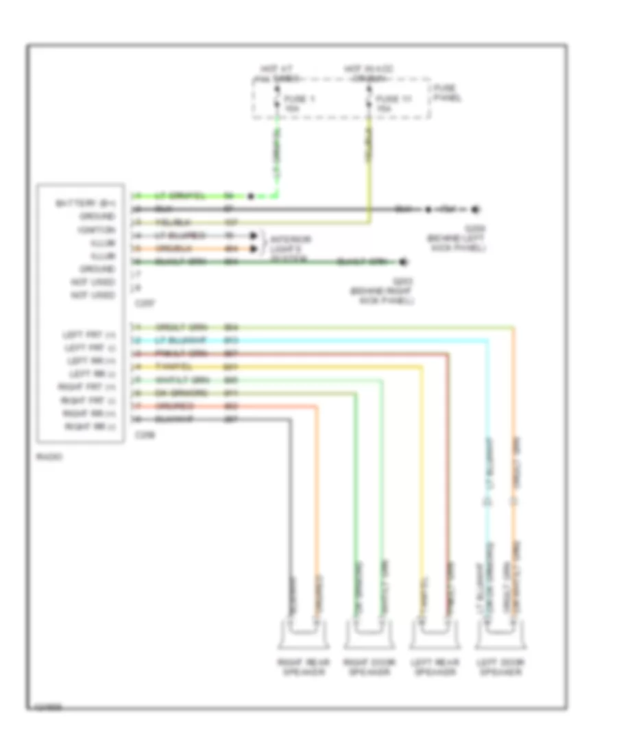
Base Radio for Ford Ranger 1994
 https://portal-diagnostov.com/license.html
Automotive Electricians Portal FZCO
Automotive Electricians Portal FZCO
https://portal-diagnostov.com/license.html
https://portal-diagnostov.com/license.html
Automotive Electricians Portal FZCO
Automotive Electricians Portal FZCOList of elements for Base Radio for Ford Ranger 1994:
- Battery (b+)
- C257
- C258
- Fuse 1 15a
- Fuse 11 15a
- Fuse panel
- G200 (behind left kick panel)
- G203 (behind right kick panel)
- Ground
- Hot at all times
- Hot in acc or run
- Ignition
- Illum
- Interior lights system
- Left door speaker
- Left frt (+)
- Left frt (-)
- Left rear speaker
- Left rr (+)
- Left rr (-)
- Not used
- Radio
- Right door speaker
- Right frt (+)
- Right frt (-)
- Right rear speaker
- Right rr (+)
- Right rr (-)
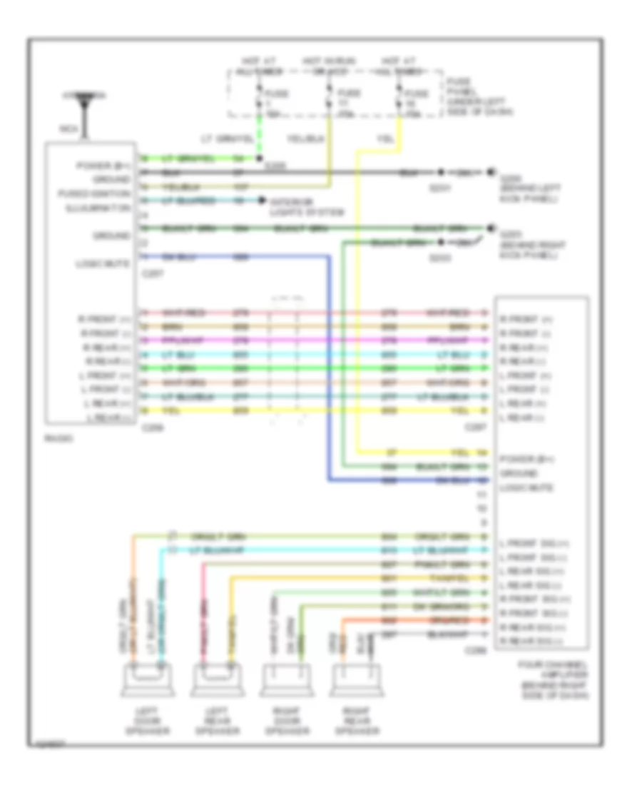
Premium Sound Radio Wiring Diagram for Ford Ranger 1994
 https://portal-diagnostov.com/license.html
Automotive Electricians Portal FZCO
Automotive Electricians Portal FZCO
https://portal-diagnostov.com/license.html
https://portal-diagnostov.com/license.html
Automotive Electricians Portal FZCO
Automotive Electricians Portal FZCOList of elements for Premium Sound Radio Wiring Diagram for Ford Ranger 1994:
- Antenna
- C257
- C258
- C297
- C298
- Four channel amplifier (behind right side of dash)
- Fuse 15a
- Fuse panel (under left side of dash)
- Fused ignition
- G200 (behind left kick panel)
- G203 (behind right kick panel)
- Ground
- Hot at all times
- Hot in run or acc
- Illulminaton
- Interior lights system
- L front (+)
- L front (-)
- L front sig (+)
- L front sig (-)
- L rear (+)
- L rear (-)
- L rear sig (+)
- L rear sig (-)
- Left door speaker
- Left rear speaker
- Logic mute
- Nca
- Power (b+)
- R front (+)
- R front (-)
- R front sig (+)
- R front sig (-)
- R rear (+)
- R rear (-)
- R rear sig (+)
- R rear sig (-)
- Radio
- Right door speaker
- Right rear speaker
- S201
- S203
- S205
STARTING/CHARGING
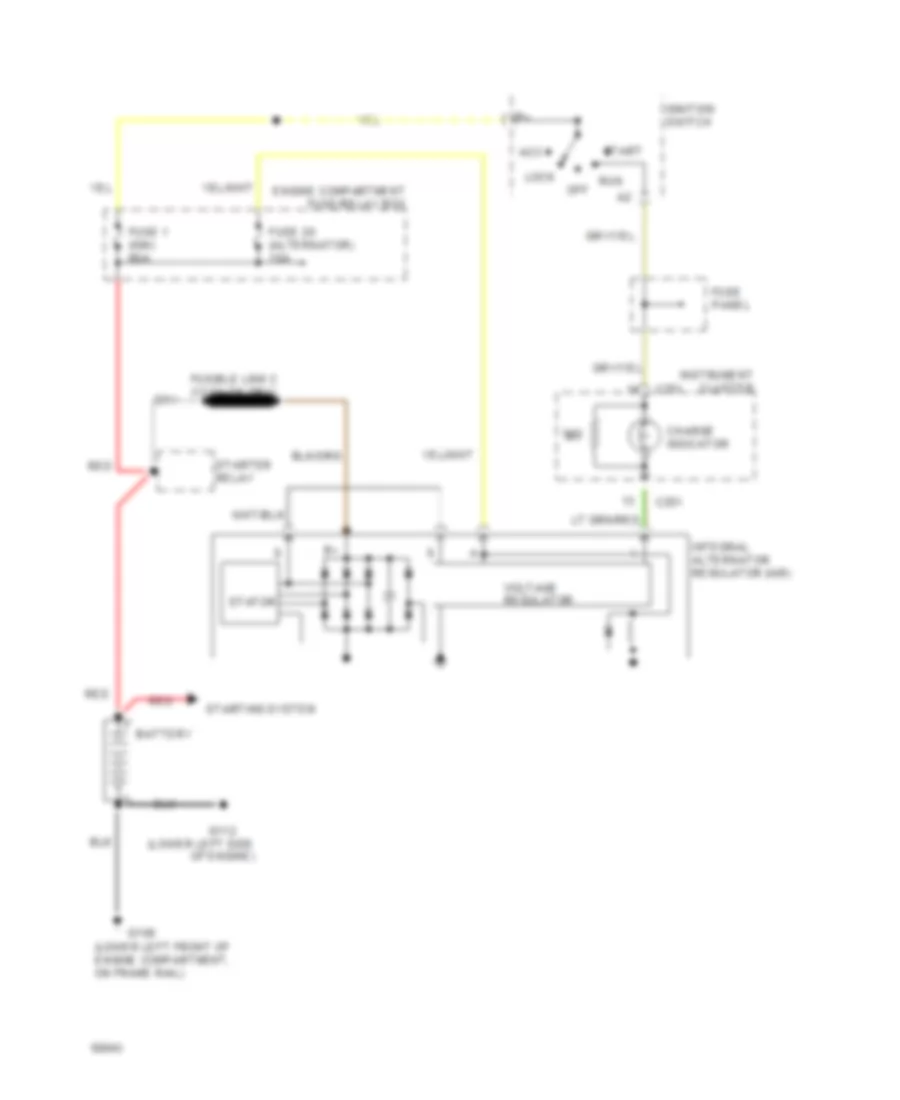
Charging Wiring Diagram for Ford Ranger 1994
 https://portal-diagnostov.com/license.html
Automotive Electricians Portal FZCO
Automotive Electricians Portal FZCO
https://portal-diagnostov.com/license.html
https://portal-diagnostov.com/license.html
Automotive Electricians Portal FZCO
Automotive Electricians Portal FZCOList of elements for Charging Wiring Diagram for Ford Ranger 1994:
- (lower left front of engine compartment, on frame rail)
- (lower left side of engine)
- Acc
- Battery
- C251
- Charge indicator
- Engine compartment fuse/relay box
- Fuse 1 (ign) 60a
- Fuse 20 (alternator) 15a
- Fuse panel
- G100
- G112
- Ignition switch
- Instrument cluster
- Integral alternator regulator (iar)
- Lock
- Off
- Red
- Run
- Start
- Starter relay
- Starting system
- Stator
- Voltage regulator
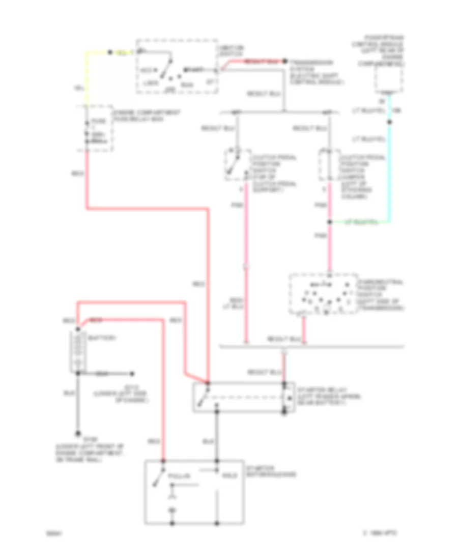
Starting Wiring Diagram for Ford Ranger 1994
 https://portal-diagnostov.com/license.html
Automotive Electricians Portal FZCO
Automotive Electricians Portal FZCO
https://portal-diagnostov.com/license.html
https://portal-diagnostov.com/license.html
Automotive Electricians Portal FZCO
Automotive Electricians Portal FZCOList of elements for Starting Wiring Diagram for Ford Ranger 1994:
- (lower left front of engine compartment, on frame rail)
- (lower left side of engine)
- 1994 vftc c
- A/t
- Acc
- Battery
- Clutch pedal position switch (top of clutch pedal support)
- Clutch pedal position switch jumper (left of steering column)
- Engine compartment fuse/relay box
- Fuse (ign) 60a
- G100
- G112
- Hold
- Ignition switch
- Lock
- M/t
- Off
- Park/neutral position switch (left side of transmission)
- Pnk
- Pnp
- Powertrain control module (left rear of engine compartment)
- Pull-in
- Red
- Run
- Start
- Starter motor/solenoid
- Starter relay (left fender apron, near battery)
- Transmission system (electric shift control module)
TRANSMISSION
2.3L
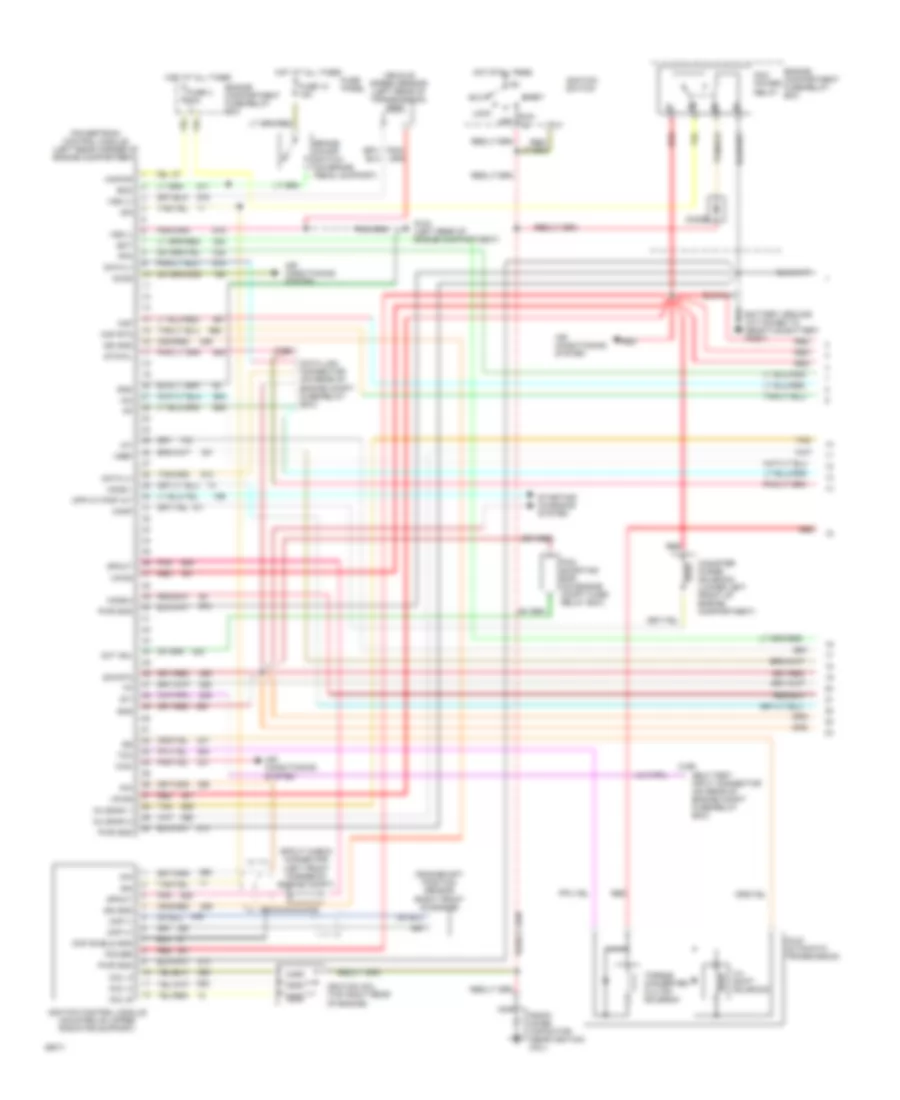
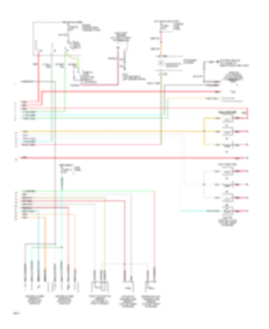
2.3L, Transmission Wiring Diagram, Federal for Ford Ranger 1994
 https://portal-diagnostov.com/license.html
Automotive Electricians Portal FZCO
Automotive Electricians Portal FZCO
https://portal-diagnostov.com/license.html
https://portal-diagnostov.com/license.html
Automotive Electricians Portal FZCO
Automotive Electricians Portal FZCOList of elements for 2.3L, Transmission Wiring Diagram, Federal for Ford Ranger 1994:
- (2.3l-top right side of engine, on throttle body) (4.0l-top left front of engine, on throttle body)
- (4x4-top of transfer case)
- (in engine compt fuse/ relay box)
- (left rear corner of engine compt)
- (mounted on left side of transmission)
- (not used)
- (on rear of engine compt fuse/relay box)
- 15a
- 2.3l only
- 3-4 shift solenoid
- 30a
- A4ld automatic trans. solenoids
- Accy
- Boo
- Brake on/ off switch (on brake pedal support)
- Case gnd
- Data link connector (partial)
- Data(+)
- Data(-)
- Ect
- Eec pwr fuse
- Engine compt fuse/relay box
- Engine coolant temp sensor (2.3l-top right front of engine, on coolant line) (4.0l-top left front of engine)
- Exterior lights (main light switch)
- Fuse 10
- Fuse panel
- G104 (left rear corner of engine compt, near pcm)
- Hot at all times
- Hot in run and start
- Iat
- Ignition control module
- Ignition switch
- Instrument cluster
- Intake air temp sensor (2.3l-right side of engine compt, on air cleaner assy) (4.0l-top left rear of engine)
- Kapwr
- Lock
- Maf
- Malfunction indicator
- Mass air flow sensor (right side of engine compt, on air cleaner assy)
- Mil
- Off
- Pcm power diode
- Pcm power relay (in engine compt fuse/ relay box)
- Pip
- Powertrain control module (partial)
- Pwr gnd
- Red
- Rtn
- Run
- Sig rtn
- Ss3-4
- Start
- Sti
- Sti connector (on rear of engine compt fuse/relay box)
- Tcc
- Throttle position sensor
- Torque converter clutch solenoid
- Vehicle speed sensor (4x2-left rear of transmission)
- Vpwr
- Vref
- Vss(+)
- Vss(-)
Transfer Case Wiring Diagram for Ford Ranger 1994
 https://portal-diagnostov.com/license.html
Automotive Electricians Portal FZCO
Automotive Electricians Portal FZCO
https://portal-diagnostov.com/license.html
https://portal-diagnostov.com/license.html
Automotive Electricians Portal FZCO
Automotive Electricians Portal FZCOList of elements for Transfer Case Wiring Diagram for Ford Ranger 1994:
- (automatic transmission)
- (between bottom of left "b" pillar and rear of cab) (ranger)
- (explorer ltd edition and electronic group only)
- (explorer)
- (left side of transmission)
- (manual transmission)
- (pwr dist box ) (or eng compt
- (ranger)
- 4x4
- 4x4 ind feed
- 4x4 input
- Acc
- Battery power
- Electronic shift control module (left rear of vehicle over wheel well) (explorer)
- Electronic shift control sw (behind center of i/p)
- F/r box)
- Fuse #13 (int f/p)
- Fuse #17 (int f/p)
- Fuse #7 (int f/p)
- Fuse #7 (or elec shift)
- G104 (on sheet metal at electronic shift control module)
- G200 (left cowl panel)
- G203 (right kick panel)
- G300 (below left seat)
- Ground
- Hot at all times
- Ign run & accy pwr
- Ignition switch
- Illum
- Instr cluster
- Lock
- Logic ground
- Low
- Low range ind feed
- Low range input
- Mag clutch coil
- Magnetic clutch coil
- Nca
- Neutral start sw
- Off
- Park/neutral position sw
- Ranger only
- Rear anti-lock brakes (rabs) module
- Red/
- Run
- Sensor
- Shift motor
- Shift position
- Speed sens feed
- Speed sens return
- Speed sensor
- Start
- Swift ctrl sw feed
- Transfer case assembly
- Transfer case motor
3.0L
3.0L, Transmission Wiring Diagram for Ford Ranger 1994
 https://portal-diagnostov.com/license.html
Automotive Electricians Portal FZCO
Automotive Electricians Portal FZCO
https://portal-diagnostov.com/license.html
https://portal-diagnostov.com/license.html
Automotive Electricians Portal FZCO
Automotive Electricians Portal FZCOList of elements for 3.0L, Transmission Wiring Diagram for Ford Ranger 1994:
- (4x4-top of transfer case)
- (in engine compt fuse/ relay box)
- (left rear corner of engine compt)
- (mounted on left side of transmission)
- (on rear of engine compt fuse/relay box)
- (top left front of engine, on throttle body)
- 15a
- 1993 3.0l
- 3-4 shift solenoid
- 30a
- 4.0l
- A4ld automatic trans. solenoids
- Accy
- Boo
- Brake on/ off switch (on brake pedal support)
- Case gnd
- Data link connector (partial)
- Data(+)
- Data(-)
- Ect
- Eec pwr fuse
- Engine compt fuse/relay box
- Engine coolant temp sensor (top left front of engine)
- Except 1993 3.0l
- Except 3.0l early prod.
- Except 4.0l
- Exterior lights (main light switch)
- Fuse 10
- Fuse panel
- G104 (left rear corner of engine compt, near pcm)
- Hot at all times
- Hot in run and start
- Iat
- Ignition control module
- Ignition switch
- Instrument cluster
- Intake air temp sensor (3.0l-right side of engine compt, on air cleaner assy) (4.0l-top left rear of engine)
- Kapwr
- Lock
- Maf
- Malfunction indicator
- Mass air flow sensor (right side of engine compt, on air cleaner assy)
- Mil
- Off
- Pcm power diode
- Pcm power relay (in engine compt fuse/ relay box)
- Pip
- Powertrain control module (partial)
- Pressure feedback egr sensor
- Pwr gnd
- Red
- Run
- Sig rtn
- Ss3-4
- Start
- Sti
- Sti connector (on rear of engine compt fuse/relay box)
- Tcc
- Throttle position sensor
- Torque converter clutch solenoid
- Vehicle speed sensor (4x2-left rear of transmission)
- Vpwr
- Vref
- Vss(+)
- Vss(-)
Transfer Case Wiring Diagram for Ford Ranger 1994
 https://portal-diagnostov.com/license.html
Automotive Electricians Portal FZCO
Automotive Electricians Portal FZCO
https://portal-diagnostov.com/license.html
https://portal-diagnostov.com/license.html
Automotive Electricians Portal FZCO
Automotive Electricians Portal FZCOList of elements for Transfer Case Wiring Diagram for Ford Ranger 1994:
- (automatic transmission)
- (between bottom of left "b" pillar and rear of cab) (ranger)
- (explorer ltd edition and electronic group only)
- (explorer)
- (left side of transmission)
- (manual transmission)
- (pwr dist box ) (or eng compt
- (ranger)
- 4x4
- 4x4 ind feed
- 4x4 input
- Acc
- Battery power
- Electronic shift control module (left rear of vehicle over wheel well) (explorer)
- Electronic shift control sw (behind center of i/p)
- F/r box)
- Fuse #13 (int f/p)
- Fuse #17 (int f/p)
- Fuse #7 (int f/p)
- Fuse #7 (or elec shift)
- G104 (on sheet metal at electronic shift control module)
- G200 (left cowl panel)
- G203 (right kick panel)
- G300 (below left seat)
- Ground
- Hot at all times
- Ign run & accy pwr
- Ignition switch
- Illum
- Instr cluster
- Lock
- Logic ground
- Low
- Low range ind feed
- Low range input
- Mag clutch coil
- Magnetic clutch coil
- Nca
- Neutral start sw
- Off
- Park/neutral position sw
- Ranger only
- Rear anti-lock brakes (rabs) module
- Red/
- Run
- Sensor
- Shift motor
- Shift position
- Speed sens feed
- Speed sens return
- Speed sensor
- Start
- Swift ctrl sw feed
- Transfer case assembly
- Transfer case motor
4.0L
4.0L, Transmission Wiring Diagram, California for Ford Ranger 1994
 https://portal-diagnostov.com/license.html
Automotive Electricians Portal FZCO
Automotive Electricians Portal FZCO
https://portal-diagnostov.com/license.html
https://portal-diagnostov.com/license.html
Automotive Electricians Portal FZCO
Automotive Electricians Portal FZCOList of elements for 4.0L, Transmission Wiring Diagram, California for Ford Ranger 1994:
- (4x4-top of transfer case)
- (in engine compt fuse/ relay box)
- (left rear corner of engine compt)
- (mounted on left side of transmission)
- (on rear of engine compt fuse/relay box)
- (top left front of engine, on throttle body)
- 15a
- 1993 3.0l
- 3-4 shift solenoid
- 30a
- 4.0l
- A4ld automatic trans. solenoids
- Accy
- Boo
- Brake on/ off switch (on brake pedal support)
- Case gnd
- Data link connector (partial)
- Data(+)
- Data(-)
- Ect
- Eec pwr fuse
- Engine compt fuse/relay box
- Engine coolant temp sensor (top left front of engine)
- Except 1993 3.0l
- Except 3.0l early prod.
- Except 4.0l
- Exterior lights (main light switch)
- Fuse 10
- Fuse panel
- G104 (left rear corner of engine compt, near pcm)
- Hot at all times
- Hot in run and start
- Iat
- Ignition control module
- Ignition switch
- Instrument cluster
- Intake air temp sensor (3.0l-right side of engine compt, on air cleaner assy) (4.0l-top left rear of engine)
- Kapwr
- Lock
- Maf
- Malfunction indicator
- Mass air flow sensor (right side of engine compt, on air cleaner assy)
- Mil
- Off
- Pcm power diode
- Pcm power relay (in engine compt fuse/ relay box)
- Pip
- Powertrain control module (partial)
- Pressure feedback egr sensor
- Pwr gnd
- Red
- Run
- Sig rtn
- Ss3-4
- Start
- Sti
- Sti connector (on rear of engine compt fuse/relay box)
- Tcc
- Throttle position sensor
- Torque converter clutch solenoid
- Vehicle speed sensor (4x2-left rear of transmission)
- Vpwr
- Vref
- Vss(+)
- Vss(-)
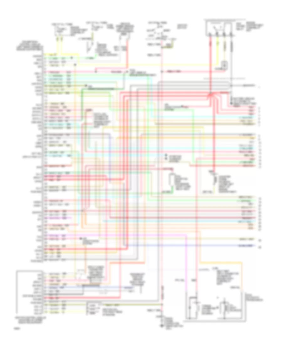
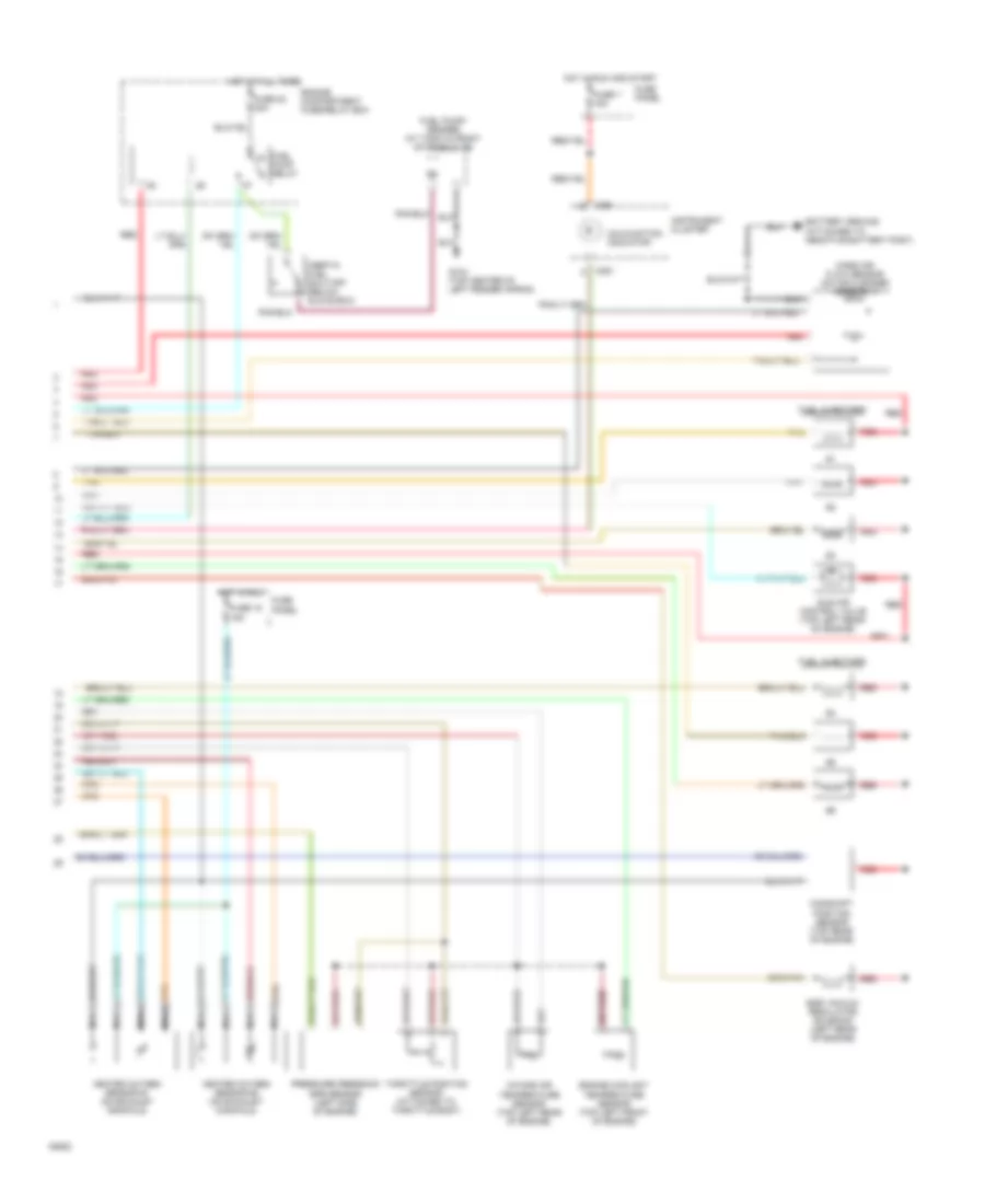
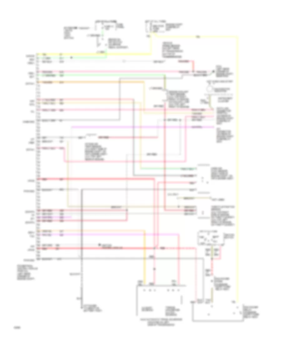
4.0L, Transmission Wiring Diagram, Federal for Ford Ranger 1994
 https://portal-diagnostov.com/license.html
Automotive Electricians Portal FZCO
Automotive Electricians Portal FZCO
https://portal-diagnostov.com/license.html
https://portal-diagnostov.com/license.html
Automotive Electricians Portal FZCO
Automotive Electricians Portal FZCOList of elements for 4.0L, Transmission Wiring Diagram, Federal for Ford Ranger 1994:
- (2.3l-top right side of engine, on throttle body) (4.0l-top left front of engine, on throttle body)
- (4x4-top of transfer case)
- (in engine compt fuse/ relay box)
- (left rear corner of engine compt)
- (mounted on left side of transmission)
- (not used)
- (on rear of engine compt fuse/relay box)
- 15a
- 2.3l only
- 3-4 shift solenoid
- 30a
- A4ld automatic trans. solenoids
- Accy
- Boo
- Brake on/ off switch (on brake pedal support)
- Case gnd
- Data link connector (partial)
- Data(+)
- Data(-)
- Ect
- Eec pwr fuse
- Engine compt fuse/relay box
- Engine coolant temp sensor (2.3l-top right front of engine, on coolant line) (4.0l-top left front of engine)
- Exterior lights (main light switch)
- Fuse 10
- Fuse panel
- G104 (left rear corner of engine compt, near pcm)
- Hot at all times
- Hot in run and start
- Iat
- Ignition control module
- Ignition switch
- Instrument cluster
- Intake air temp sensor (2.3l-right side of engine compt, on air cleaner assy) (4.0l-top left rear of engine)
- Kapwr
- Lock
- Maf
- Malfunction indicator
- Mass air flow sensor (right side of engine compt, on air cleaner assy)
- Mil
- Off
- Pcm power diode
- Pcm power relay (in engine compt fuse/ relay box)
- Pip
- Powertrain control module (partial)
- Pwr gnd
- Red
- Rtn
- Run
- Sig rtn
- Ss3-4
- Start
- Sti
- Sti connector (on rear of engine compt fuse/relay box)
- Tcc
- Throttle position sensor
- Torque converter clutch solenoid
- Vehicle speed sensor (4x2-left rear of transmission)
- Vpwr
- Vref
- Vss(+)
- Vss(-)
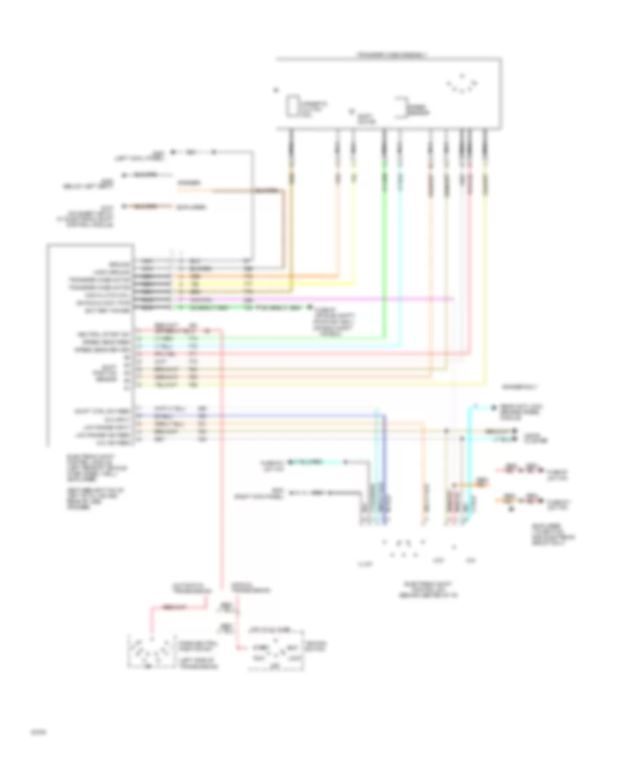
Transfer Case Wiring Diagram for Ford Ranger 1994
 https://portal-diagnostov.com/license.html
Automotive Electricians Portal FZCO
Automotive Electricians Portal FZCO
https://portal-diagnostov.com/license.html
https://portal-diagnostov.com/license.html
Automotive Electricians Portal FZCO
Automotive Electricians Portal FZCOList of elements for Transfer Case Wiring Diagram for Ford Ranger 1994:
- (automatic transmission)
- (between bottom of left "b" pillar and rear of cab) (ranger)
- (explorer ltd edition and electronic group only)
- (explorer)
- (left side of transmission)
- (manual transmission)
- (pwr dist box ) (or eng compt
- (ranger)
- 4x4
- 4x4 ind feed
- 4x4 input
- Acc
- Battery power
- Electronic shift control module (left rear of vehicle over wheel well) (explorer)
- Electronic shift control sw (behind center of i/p)
- F/r box)
- Fuse #13 (int f/p)
- Fuse #17 (int f/p)
- Fuse #7 (int f/p)
- Fuse #7 (or elec shift)
- G104 (on sheet metal at electronic shift control module)
- G200 (left cowl panel)
- G203 (right kick panel)
- G300 (below left seat)
- Ground
- Hot at all times
- Ign run & accy pwr
- Ignition switch
- Illum
- Instr cluster
- Lock
- Logic ground
- Low
- Low range ind feed
- Low range input
- Mag clutch coil
- Magnetic clutch coil
- Nca
- Neutral start sw
- Off
- Park/neutral position sw
- Ranger only
- Rear anti-lock brakes (rabs) module
- Red/
- Run
- Sensor
- Shift motor
- Shift position
- Speed sens feed
- Speed sens return
- Speed sensor
- Start
- Swift ctrl sw feed
- Transfer case assembly
- Transfer case motor
WARNING SYSTEMS
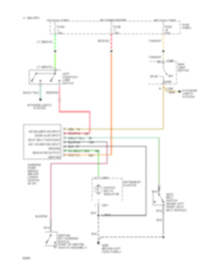
Warning System Wiring Diagrams for Ford Ranger 1994
 https://portal-diagnostov.com/license.html
Automotive Electricians Portal FZCO
Automotive Electricians Portal FZCO
https://portal-diagnostov.com/license.html
https://portal-diagnostov.com/license.html
Automotive Electricians Portal FZCO
Automotive Electricians Portal FZCOList of elements for Warning System Wiring Diagrams for Ford Ranger 1994:
- 1994 vftc c
- C250
- C251
- C286
- Door ajar input
- Exterior lights system
- Fasten belts indicator
- Fuse 15a
- Fuse panel
- G200 (behind left cowl panel)
- Ground
- Head
- Headlamps on input
- Hot at all times
- Hot in run or start
- Ignition
- Ignition key warning switch (part of ignition switch assembly)
- Indicator output
- Instrument cluster
- Interior lights system
- Key in ignition input
- Left courtesy lamp switch
- Main light switch
- Nca
- Off
- Park
- Red/pnk
- Seat belt fastened
- Seat belt switch (inside left front seat belt buckle)
- Warning chime module (below lower center of i/p)
WIPER/WASHER
Wiper/Washer Wiring Diagram for Ford Ranger 1994
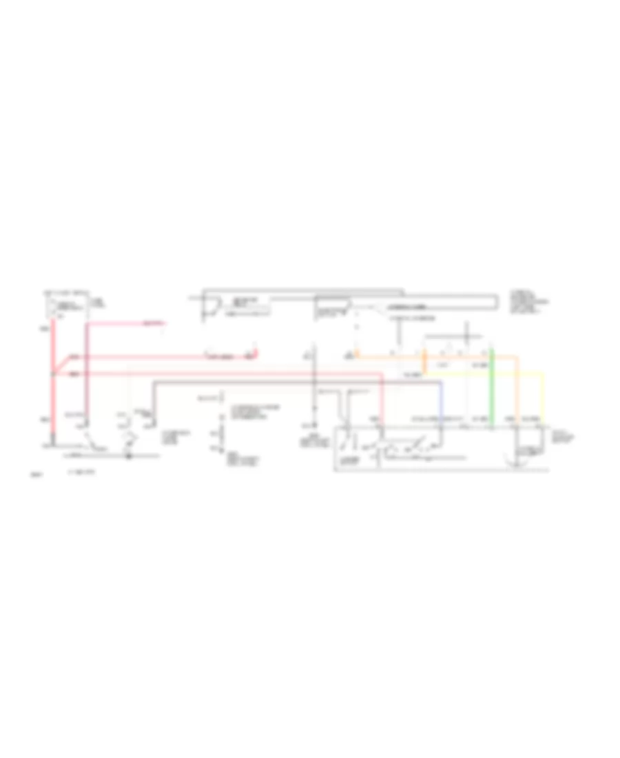 https://portal-diagnostov.com/license.html
Automotive Electricians Portal FZCO
Automotive Electricians Portal FZCO
https://portal-diagnostov.com/license.html
https://portal-diagnostov.com/license.html
Automotive Electricians Portal FZCO
Automotive Electricians Portal FZCOList of elements for Wiper/Washer Wiring Diagram for Ford Ranger 1994:
- (behind left cowl panel)
- (not used)
- 1994 vftc c
- Circuit breaker 2
- Electronic switch
- Fuse panel
- G200
- G203 (behind right cowl panel)
- Governor relay
- Hot in accy or run
- Int
- Interval adjust
- Interval governor (wiper/washer) (left side of ashtray)
- Interval override
- Interval timer
- Multi- function switch
- Nca
- Off
- Park
- Red
- Run
- Washer switch
- Windshield washer pump motor (on reservoir)
- Windshield wiper motor

 Čeština
 Dansk
Dansk Deutsch
 Ελληνικά
 English
 English
 Español
 Suomi
Suomi Français
 Français
 עברית
עברית Hrvatski
 Magyar
 Italiano
 日本語
日本語 Nederlands
 Polski
 Português
 Português
 Română
 Русский
 Slovenčina
 Slovenščina
 Svenska
 Türkçe
 中文 (中国)
