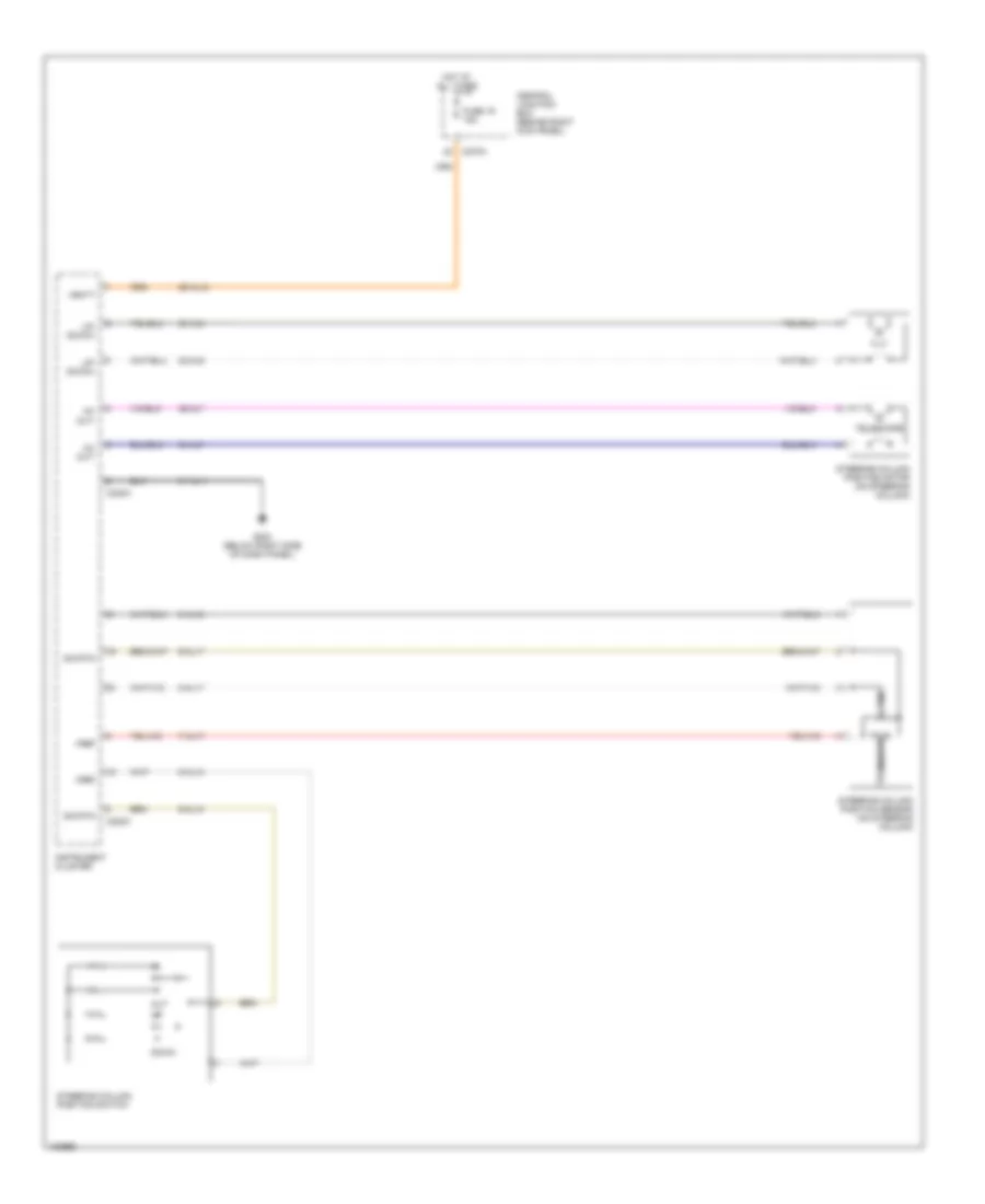
AIR CONDITIONING
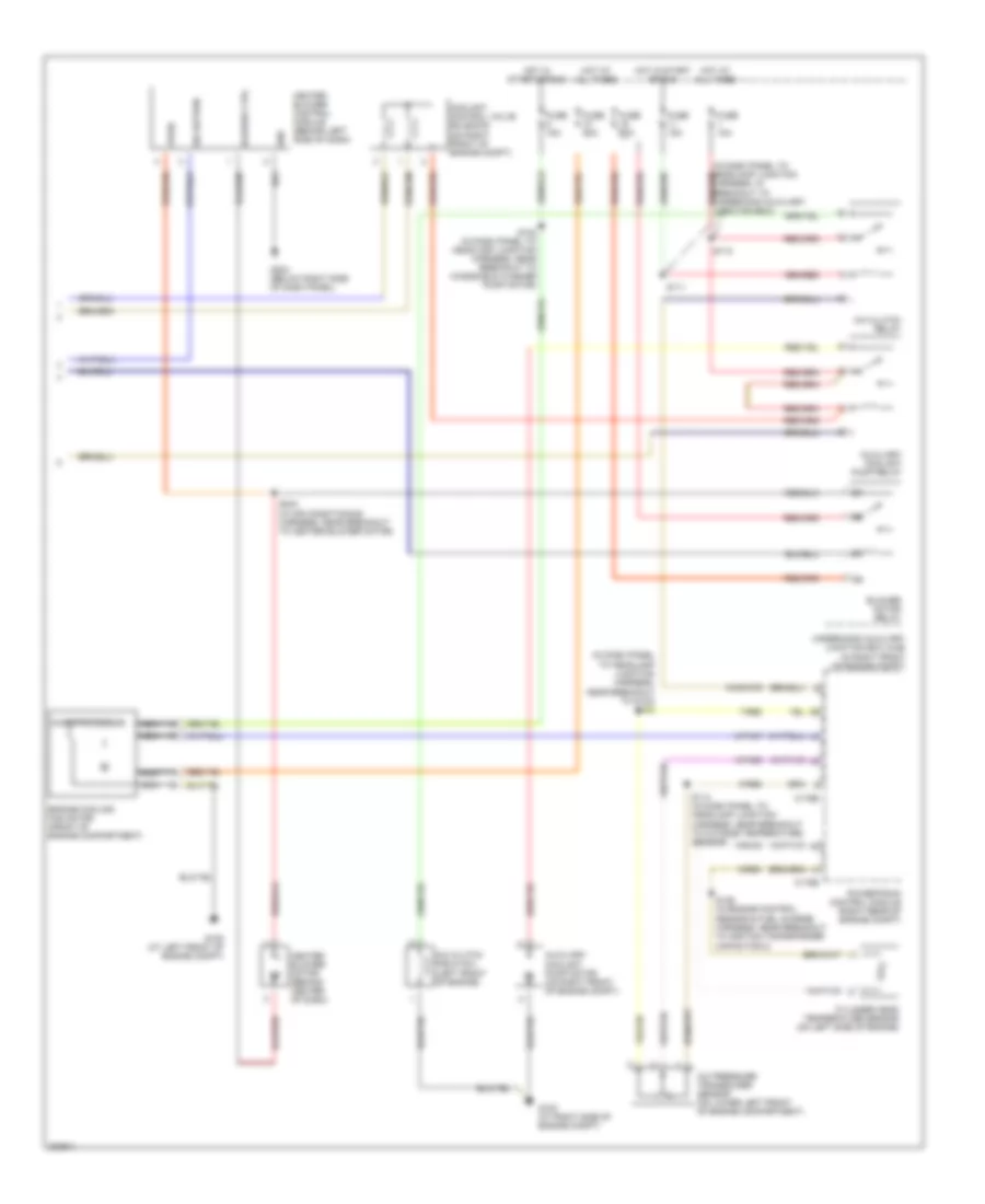
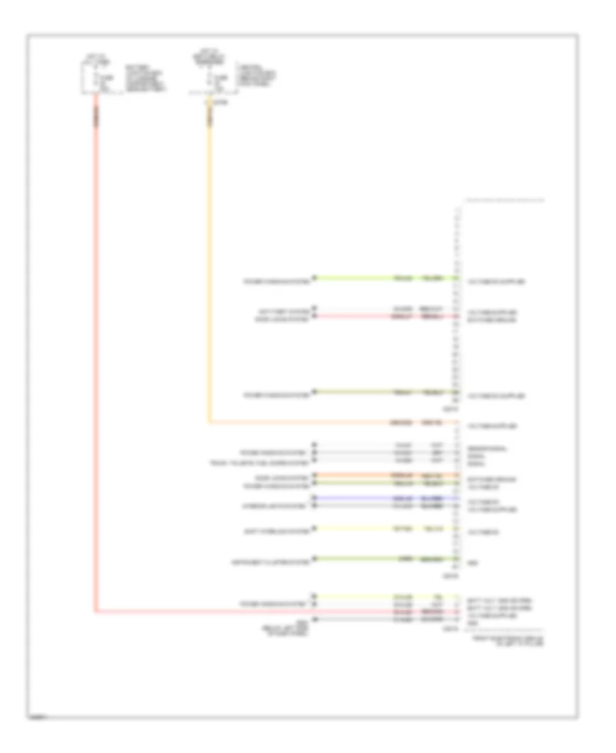
Automatic A/C Wiring Diagram (1 of 2) for Ford Thunderbird 2005
 https://portal-diagnostov.com/license.html
Automotive Electricians Portal FZCO
Automotive Electricians Portal FZCO
https://portal-diagnostov.com/license.html
https://portal-diagnostov.com/license.html
Automotive Electricians Portal FZCO
Automotive Electricians Portal FZCO
List of elements for Automatic A/C Wiring Diagram (1 of 2) for Ford Thunderbird 2005:
- (in main harness, near breakout to g200)
- (in main harness, near breakout to right center image speaker) s214
- 10-fa53
- 20-fa10
- 29-fa10
- 31-fa10
- 31s-fa23
- 32-fb5
- 32-fb6
- 32-fb7
- 32-fb8
- 33-fb5
- 33-fb6
- 33-fb7
- 33-fb8
- 4-fa10
- 5-fa10
- 7-fa1
- 8-fa44
- 8-fa45
- 8-fa47
- 8-fa48
- 8-fa49
- 8-fa51
- 8-fa53
- 8-fb5
- 8-fb6
- 8-fb7
- 8-fb8
- 9-fa2
- 9-fa3
- 9-fa44
- 9-fa48
- 9-fa49
- 9-fb8
- 91s-fa76
- 91s-fb3
- 91s-fb4
- Blower motor control
- C228a
- C228b
- C270a
- Central junction box (behind right kick panel)
- Computer data lines system
- Defrost mode actuator (behind center of dash, on hvac assembly)
- Electronic automatic temperature control module (behind center of dash)
- Evaporator discharge air temperature sensor (behind center of dash)
- Floor mode actuator (behind center of dash, on hvac assembly)
- Fresh/recirculation door actuator (behind center of dash, on hvac assembly)
- Fuse 10a
- Fuse 5a
- G203 (below right side of dash panel)
- Gnd
- Hot at all times
- Hot in run
- In-vehicle temperature sensor (behind center of dash)
- Left discharge temperature sensor (behind left side of dash)
- Micro- processor
- Motor control
- Near breakout to right center image speaker)
- Outside temperature sensor (on right front of engine compt)
- Panel mode actuator (behind right side of dash, on hvac assembly)
- Right discharge temperature sensor (behind right side of dash)
- S210
- S212 (in main harness, near breakout to passenger air bag module)
- Scp +
- Scp -
- Sensor return
- Sensor signal
- Sensor signal return
- Sensor voltage
- Signal 2
- Sunload sensor (on top of dash, above glove box)
- Switched (batt/gnd/open)
- Switched gnd
- Vbatt
- Vpwr
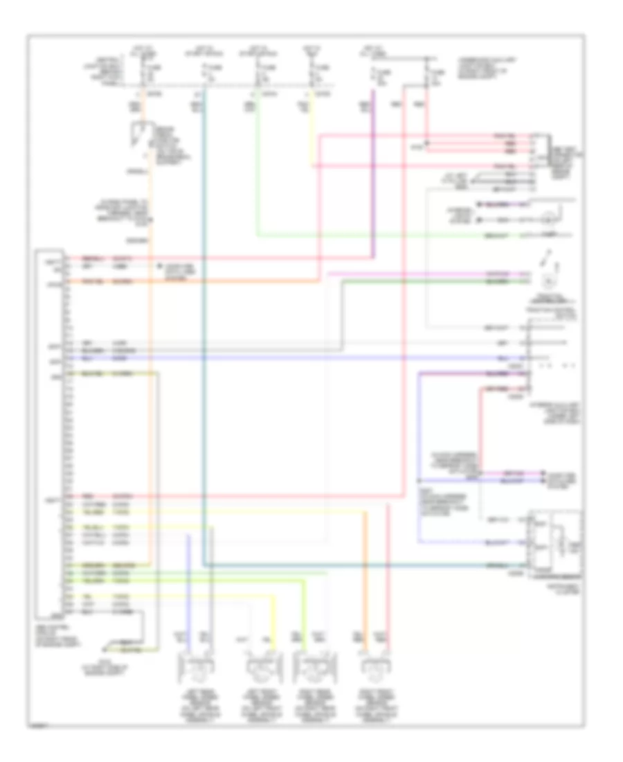
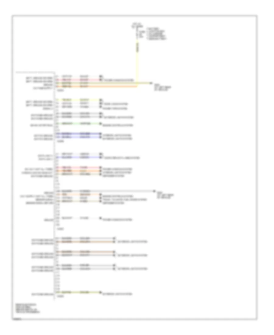
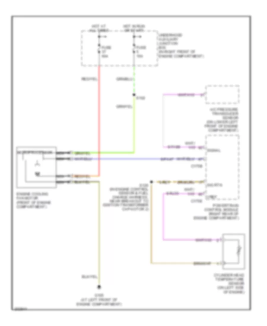
Automatic A/C Wiring Diagram (2 of 2) for Ford Thunderbird 2005
 https://portal-diagnostov.com/license.html
Automotive Electricians Portal FZCO
Automotive Electricians Portal FZCO
https://portal-diagnostov.com/license.html
https://portal-diagnostov.com/license.html
Automotive Electricians Portal FZCO
Automotive Electricians Portal FZCOList of elements for Automatic A/C Wiring Diagram (2 of 2) for Ford Thunderbird 2005:
- (in dash panel to headlamp junction harness, near breakout to g103) s104
- 7-re8
- 8-fa88
- 8-pa47
- 8-rj33
- 9-re1
- 9-re8
- 91s-fa79
- A/c clutch field coil (left front of engine)
- A/c clutch relay
- A/c pressure transducer sensor (on lower left front of engine compartment)
- Auxiliary coolant pump motor (on right front of engine compt)
- Auxiliary coolant pump relay
- Blower ctrl
- Blower motor relay
- C175b
- C175e
- Coolant control valve solenoid (on right front of engine compt)
- Cylinder head temperature sensor (on left side of engine)
- Engine cooling fan motor (front of engine compartment)
- Fuse 10a
- Fuse 15a
- Fuse 30a
- Fuse 60a
- G102 (at right side of engine compt)
- G105 (at left front of engine compt)
- G203 (below right side of dash panel)
- Gnd
- Harness, in breakout to underhood auxiliary junction box)
- Heater blower control module (behind left side of dash)
- Heater blower motor (behind center of dash)
- Hot at all times
- Hot in start or run
- Microprocessor
- Nca
- Powertrain control module (right rear of engine compt)
- S102 (in dash panel to headlamp junction harness, near breakout to windshield washer pump motor)
- S111
- S112
- S114 (in dash panel to headlamp junction harness, near breakout to outside temperature sensor)
- S126 (in engine control sensor & fuel charge harness, near breakout to ignition transformer capacitor 2)
- S234 (in air conditioning harness, near breakout to heater blower motor)
- Sig return
- Underhood auxiliary junction box (ajb) (in right front of engine compt)
- Vpwr
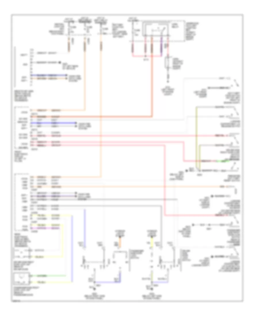
ANTI-LOCK BRAKES
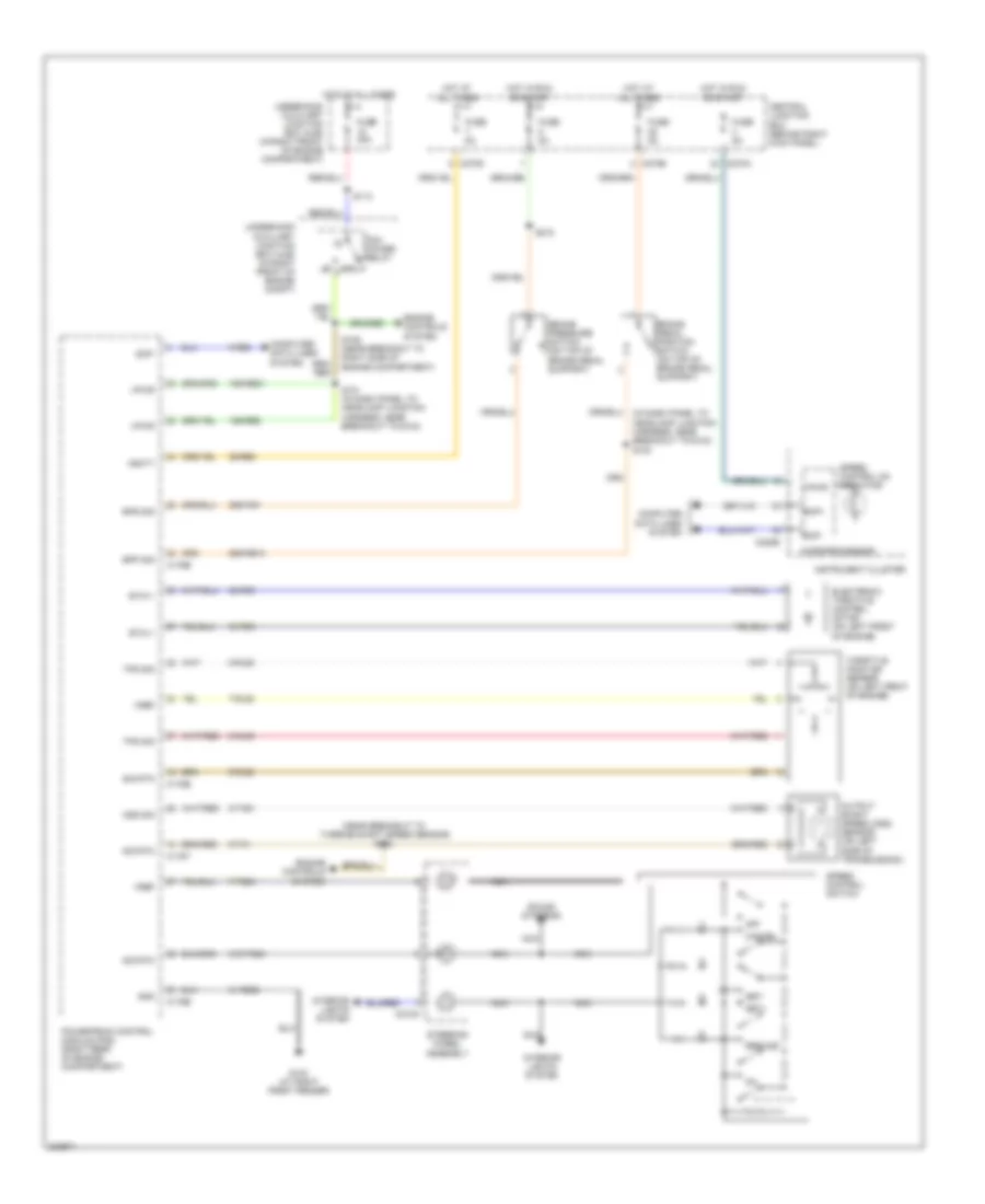
Anti-lock Brakes Wiring Diagram for Ford Thunderbird 2005
 https://portal-diagnostov.com/license.html
Automotive Electricians Portal FZCO
Automotive Electricians Portal FZCO
https://portal-diagnostov.com/license.html
https://portal-diagnostov.com/license.html
Automotive Electricians Portal FZCO
Automotive Electricians Portal FZCOList of elements for Anti-lock Brakes Wiring Diagram for Ford Thunderbird 2005:
- (at left "a" pillar) g202
- (in dash panel to headlamp junction harness, near breakout to g103) s100
- (in main harness, near breakout to defrost mode actuator) s206
- 20-cf6a
- 29s-cf58
- 30-cf13
- 30-cf6a
- 31-cf6a
- 31-cf6b
- 31s-cf45
- 4-cf6
- 4-ee6
- 5-cf6
- 7-cf32
- 7-cf34
- 7-cf38
- 7-cf40
- 8-cf32
- 8-cf34
- 8-cf38
- 8-cf40
- 8-cf54
- Abs control module (on right front of engine compt)
- Abs ind
- Abs test connector nca (on left rear of engine compt)
- Brake pedal position switch (on top of brake pedal support)
- C220b
- C270a
- C270b
- C270d
- C283c
- C283d
- Central junction box (behind right kick panel)
- Computer data lines system
- Computer datalines system
- Fuse 30a
- Fuse 40a
- Fuse 5a
- G102 (at right side of engine compt)
- Gnd
- Hot at all times
- Hot in run
- Hot in start or run
- Illum
- Instrument cluster
- Interior auxiliary junction box (under left side of dash)
- Interior lights system
- Iso
- Left front wheel speed sensor (on left front wheel spindle assembly)
- Left rear wheel speed sensor (on left rear wheel spindle assembly)
- Microprocessor
- Red
- Right front wheel speed sensor (on right front wheel spindle assembly)
- Right rear wheel speed sensor (on right rear wheel spindle assembly)
- S120
- S207 (in main harness, near breakout to defrost mode actuator)
- Scp+
- Scp-
- Traction control off
- Traction control switch
- Underhood auxiliary junction box (in right front of engine compt)
- Vbatt
- Vpwr
ANTI-THEFT
Forced Entry Wiring Diagram for Ford Thunderbird 2005
 https://portal-diagnostov.com/license.html
Automotive Electricians Portal FZCO
Automotive Electricians Portal FZCO
https://portal-diagnostov.com/license.html
https://portal-diagnostov.com/license.html
Automotive Electricians Portal FZCO
Automotive Electricians Portal FZCOList of elements for Forced Entry Wiring Diagram for Ford Thunderbird 2005:
- (behind right kick panel)
- (on center rear of luggage compt)
- (rear of passenger door)
- 29-aa17
- 29s-aa83
- 29s-dk21
- 29s-dk31
- 30-aa79
- 30s-gl46
- 30s-gl47
- 31-aa17
- 32-aa11
- 32-aa21
- 33-aa10
- 33-aa20
- 4-eg11
- 4-eg12a
- 4-eg13a
- 5-eg11
- 5-eg12a
- 5-eg13a
- 8-aa10
- 8-aa11
- 8-aa20
- 8-aa21
- 8-aa30a
- 8-gl20
- 8-gl7
- 91s-gj7
- Anti-theft hood switch (on top left front of engine compt)
- Battery junction box (in luggage compt, near battery)
- C201a
- C201c
- C201d
- C201e
- C270b
- C270d
- C420b
- C420c
- C420e
- C420f
- Central junction box
- Computer data lines system
- Driver side door lock switch
- Driver side front door ajar switch (rear of driver door)
- Driver side front door lock unit (rear of driver door)
- Front electronic module (in left "a" pillar)
- Fuse 15a
- Fuse 5a
- G101 (left front of engine compt)
- G203 (below right side of dash panel)
- G204 (below left side of dash panel)
- G401 (at right side of luggage compt)
- G402 (at left rear of vehicle)
- Gnd
- Horn (on right front of engine compt)
- Horn relay
- Hot at all times
- Hot w/ ssp 2 relay energized
- Hot w/ ssp 4 relay energized
- Interior lights system
- Lock
- Luggage compartment lid ajar switch (on center rear of luggage compt)
- Luggage compartment lid release solenoid
- Luggage compartment lid release switch
- Passenger side door lock switch
- Passenger side front door ajar switch (rear of passenger door)
- Passenger side front door lock unit
- Perimeter anti-theft reset switch
- Pwr
- Rear electronic module (rem) (behind seats, on vehicle crossbeam)
- Remote keyless entry module (behind seats, on vehicle crossbeam)
- S110
- S500
- S601
- Scp +
- Scp -
- Sens sig
- Sw gnd
- Underhood auxiliary junction box (in right front of engine compt)
- Unlock
- Vbatt
- Vpwr
- Vref
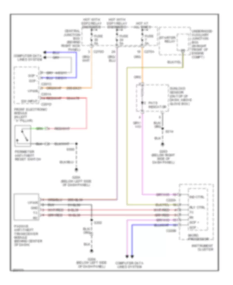
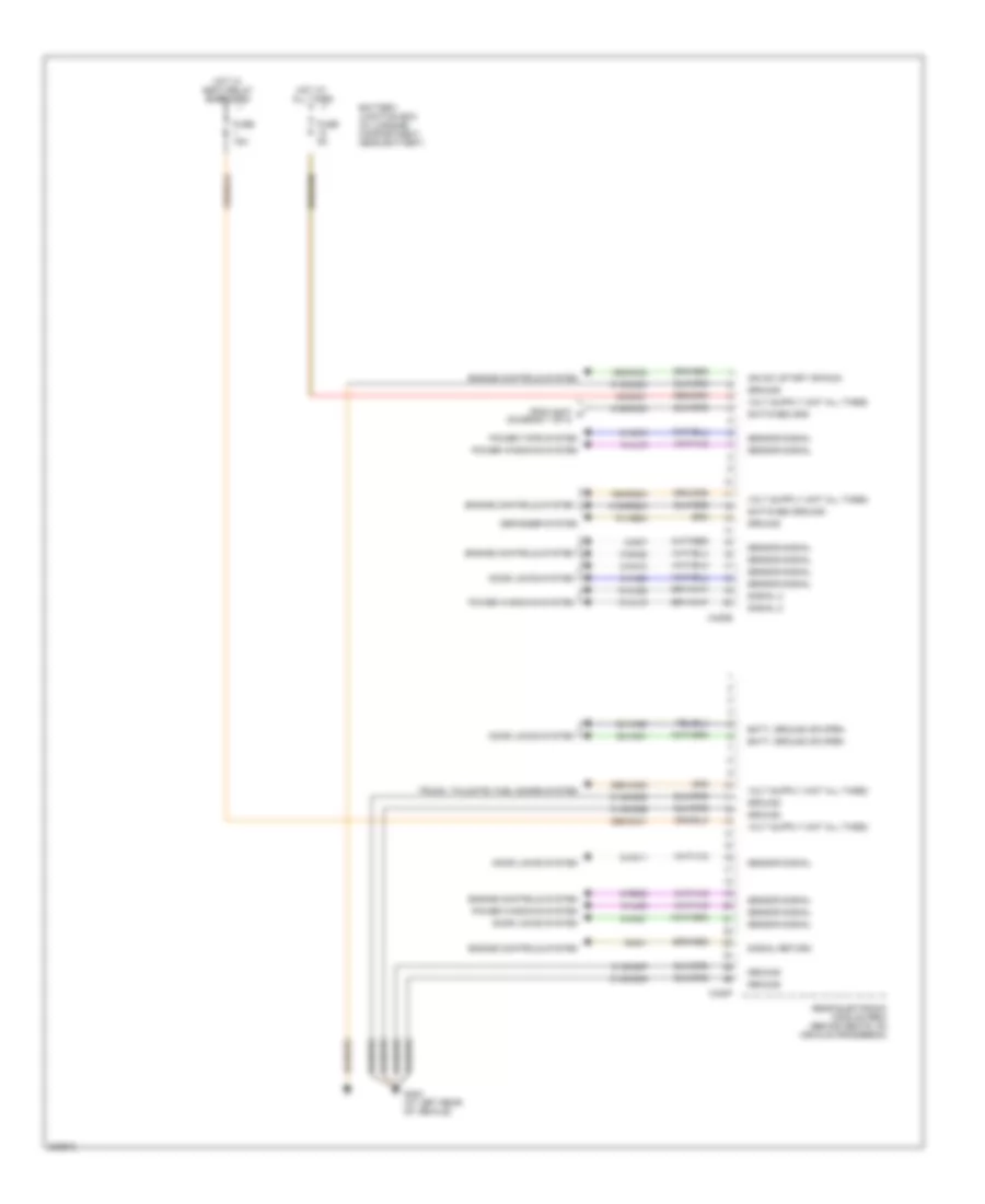
Passive Anti-theft Wiring Diagram for Ford Thunderbird 2005
 https://portal-diagnostov.com/license.html
Automotive Electricians Portal FZCO
Automotive Electricians Portal FZCO
https://portal-diagnostov.com/license.html
https://portal-diagnostov.com/license.html
Automotive Electricians Portal FZCO
Automotive Electricians Portal FZCOList of elements for Passive Anti-theft Wiring Diagram for Ford Thunderbird 2005:
- 10-gl36
- 29s-dk21
- 29s-gl36
- 30-aa79
- 31-gl36
- 4-eg11
- 5-eg11
- 8-gl36
- C201a
- C201c
- C201d
- C220a
- C220b
- C270a
- C270d
- Central junction box (behind right kick panel)
- Computer data lines system
- Front electronic module (in left ``a" pillar)
- Fuse 5a
- G203 (below right side of dash panel)
- G204 (below left side of dash panel)
- Gnd
- Hot at all times
- Hot with ssp1 relay energized
- Hot with ssp2 relay energized
- Ind ctrl
- Instrument cluster
- Micro processor
- Passive anti-theft transceiver module (behind center of dash)
- Pats indicator
- Perimeter anti-theft reset switch
- Rly ctrl
- S202
- S214
- S500
- Scp +
- Scp -
- Starter relay
- Sunload sensor (on top of dash, above glove box)
- Sw input
- Underhood auxiliary junction box (in right front of engine compt)
- Vpwr
BODY CONTROL MODULES
Body Control Modules Wiring Diagram (1 of 4) for Ford Thunderbird 2005
 https://portal-diagnostov.com/license.html
Automotive Electricians Portal FZCO
Automotive Electricians Portal FZCO
https://portal-diagnostov.com/license.html
https://portal-diagnostov.com/license.html
Automotive Electricians Portal FZCO
Automotive Electricians Portal FZCOList of elements for Body Control Modules Wiring Diagram (1 of 4) for Ford Thunderbird 2005:
- (in left "a" pillar)
- 10-ag15
- 29-dk20
- 29s-dk21
- 31-aj81
- 31-dk20
- 31-dk20a
- 31-dk20b
- 31-dk20c
- 31-dk20d
- 31s-dk21
- 31s-ld9
- 31s-le15
- 31s-le16
- 31s-le22
- 31s-le23
- 31s-lf16
- 31s-lf17
- 31s-lf7
- 31s-lf8
- 31s-lg11
- 31s-lg18
- 4-eg11
- 5-eg11
- 7-aj81
- 8-ag15
- 8-ce9
- 8-gc21
- 8-gc7
- 8-gc8
- 8-gl7
- 9-ce9
- 91s-gj7
- A/c demand signal
- Battery junction box (in luggage compt, near battery)
- C201a
- C201b
- C201c
- C270d
- Central junction box (behind right kick panel)
- Computer data lines system
- Door locks system
- Exterior lights system
- Front electronic module
- Fuse 10a
- Fuse 5a
- G202 (at left "a" pillar)
- Gnd
- Headlights system
- Horns system
- Hot at all times
- Hot w/ ssp 2 relay energized
- Instrument cluster system
- Power steering valve solenoid (on lower left rear of engine compt)
- Power tops system
- Power windows system
- S407 (in body main harness, in breakout to p93)
- Scp+
- Scp-
- Sens sig rtn
- Sensor signal
- Ssp 4 relay
- Switched ground
- To rear electronic module (diagram 4 of 4)
- Vbatt
Body Control Modules Wiring Diagram (2 of 4) for Ford Thunderbird 2005
 https://portal-diagnostov.com/license.html
Automotive Electricians Portal FZCO
Automotive Electricians Portal FZCO
https://portal-diagnostov.com/license.html
https://portal-diagnostov.com/license.html
Automotive Electricians Portal FZCO
Automotive Electricians Portal FZCOList of elements for Body Control Modules Wiring Diagram (2 of 4) for Ford Thunderbird 2005:
- 10-aj81
- 29s-dk22
- 30-aa79
- 30-aj80
- 30s-gl46
- 30s-gl47
- 31-aj80
- 31-lc10
- 32-aj26
- 33-aj26
- 64s-lh2
- 7s-aj16
- 7s-aj40
- 7s-aj41
- 7s-ta33
- 8-aa30
- 8-aj81
- 9-rp9
- Anti-theft system
- Batt volt, gnd or open
- Battery junction box (in luggage compartment, near battery)
- C201d
- C201e
- C201g
- C270b
- Central junction box (behind right kick panel)
- Door locks system
- Front electronic module (in left "a" pillar)
- Fuse 10a
- Fuse 30a
- G204 (below left side of dash panel)
- Gnd
- Hot at all times
- Hot w/ ssp 2 relay energized
- Instrument cluster system
- Interior lights system
- Power windows system
- Sensor signal
- Shift interlock system
- Signal
- Switched ground
- Trunk, tailgate, fuel doors system
- Voltage dc
Body Control Modules Wiring Diagram (3 of 4) for Ford Thunderbird 2005
 https://portal-diagnostov.com/license.html
Automotive Electricians Portal FZCO
Automotive Electricians Portal FZCO
https://portal-diagnostov.com/license.html
https://portal-diagnostov.com/license.html
Automotive Electricians Portal FZCO
Automotive Electricians Portal FZCOList of elements for Body Control Modules Wiring Diagram (3 of 4) for Ford Thunderbird 2005:
- 10-ag24
- 15-rp12b
- 29s-dk30
- 30-aj71
- 31-aj71
- 31-aj82
- 31-dk30h
- 31s-lb25
- 31s-lf10
- 31s-lf11
- 31s-lf19
- 31s-lf20
- 31s-lf21
- 31s-lg14
- 31s-lg16
- 31s-lg21
- 31s-lg6
- 31s-lg9
- 32-aa11
- 32-aj27
- 33-aa10
- 33-aj27
- 4-eg12a
- 5-eg12a
- 7-aj82
- 7-lh1
- 8-gl20
- 9-hb23
- 91s-hb23
- Batt, ground or open
- Battery junction box (in luggage compartment, near battery)
- C420a
- C420b
- C420c
- C420d
- Computer data lines system
- Data link (+)
- Data link (-)
- Dc volt (hot all times)
- Defogger system
- Door locks system
- Engine controls system
- Exterior lights system
- Fuse 30a
- G402 (at left rear of vehicle)
- Ground
- Hot at all times
- Ign sw (start/run)
- Interior lights system
- Power tops system
- Power windows system
- Rear electronic module (rem) (behind seats, on vehicle crossbeam)
- Sensor signal
- Sensor signal return
- Signal 2
- Switch ground
- Switched ground
- Trunk, tailgate, fuel doors system
- Window/lock sw bias out
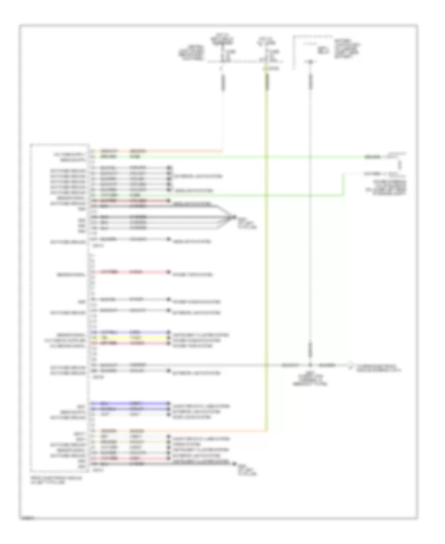
Body Control Modules Wiring Diagram (4 of 4) for Ford Thunderbird 2005
 https://portal-diagnostov.com/license.html
Automotive Electricians Portal FZCO
Automotive Electricians Portal FZCO
https://portal-diagnostov.com/license.html
https://portal-diagnostov.com/license.html
Automotive Electricians Portal FZCO
Automotive Electricians Portal FZCOList of elements for Body Control Modules Wiring Diagram (4 of 4) for Ford Thunderbird 2005:
- 10-aj18
- 10-aj82
- 15s-dk32
- 15s-rg2a
- 29s-aa83
- 29s-dk31
- 30-dk31
- 31-dk30c
- 31-dk30d
- 31-dk30e
- 31-dk30f
- 31-dk30g
- 31s-dk30
- 31s-rg2a
- 32-aa21
- 33-aa20
- 8-aa10
- 8-aa11
- 8-aa20
- 8-aa21
- 8-ag16
- 8-aj18
- 8-aj82
- 8-ga25
- 8-ga7
- 8-re32
- 9-ga1
- 91-hb24
- Batt, ground or open
- Battery junction box (in luggage compartment, near battery)
- C420e
- C420f
- Defogger system
- Door locks system
- Engine controls system
- From s407 a (diagram 1 of 4)
- Fuse 15a
- Fuse 5a
- G402 (at left rear of vehicle)
- Ground
- Hot at all times
- Hot w/ ssp 4 relay energized
- Ign sw (start or run)
- Power tops system
- Power windows system
- Rear electronic module (rem) (behind seats, on vehicle crossbeam)
- Sensor signal
- Signal 2
- Signal return
- Switched gnd
- Switched ground
- Trunk, tailgate, fuel doors system
COMPUTER DATA LINES
Computer Data Lines Wiring Diagram for Ford Thunderbird 2005
 https://portal-diagnostov.com/license.html
Automotive Electricians Portal FZCO
Automotive Electricians Portal FZCO
https://portal-diagnostov.com/license.html
https://portal-diagnostov.com/license.html
Automotive Electricians Portal FZCO
Automotive Electricians Portal FZCOList of elements for Computer Data Lines Wiring Diagram for Ford Thunderbird 2005:
- (below right side of dash panel) g203
- (in main harness, near breakout to c213)
- (near breakout to c248)
- (near breakout to defrost mode actuator)
- 4-cf6
- 4-ec7
- 4-ee1
- 4-ee6
- 4-eg11
- 4-eg12a
- 4-eg13a
- 4-fa10
- 4-re8
- 5-cf6
- 5-ec7
- 5-eg11
- 5-eg12a
- 5-eg13a
- 5-fa10
- 5-re8
- 7-re14
- Abs control module (on right front of engine compt)
- Abs test connector (on left rear of engine compt)
- Audio unit
- C175b
- C201c
- C220b
- C228b
- C240c
- C270a
- C283a
- C283b
- C283c
- C283d
- C310a
- C420c
- Can+
- Can-
- Central junction box (behind right kick panel)
- Data link connector (under left side of dash)
- Electronic automatic temperature control module (behind center of dash)
- Feps
- Front electronic module (in left "a" pillar)
- Fuse 6 10a
- G203 (below right side of dash panel)
- G204 (below left side of dash panel)
- Hot at all times
- Instrument cluster
- Interior auxiliary junction box (under left side of dash)
- Iso
- Nca
- Powertrain control module (right rear of engine compartment)
- Rear electronic module (rem) (behind seats, on vehicle crossbeam)
- Remote keyless entry module (behind seats, on vehicle crossbeam)
- Restraints control module (in center console)
- S201
- S205
- S206
- S207 (near breakout to defrost mode actuator)
- S214
- S217
- S222
- Scp+
- Scp-
COOLING FAN
Cooling Fan Wiring Diagram for Ford Thunderbird 2005
 https://portal-diagnostov.com/license.html
Automotive Electricians Portal FZCO
Automotive Electricians Portal FZCO
https://portal-diagnostov.com/license.html
https://portal-diagnostov.com/license.html
Automotive Electricians Portal FZCO
Automotive Electricians Portal FZCOList of elements for Cooling Fan Wiring Diagram for Ford Thunderbird 2005:
- 8-fa88
- 8-pa47
- 8-rj33
- 9-re1
- A/c pressure transducer sensor (on lower left front of engine compartment)
- C175b
- C175e
- Cylinder head temperature sensor (on left side of engine)
- Engine cooling fan motor (front of engine compartment)
- Fuse 15a
- Fuse 60a
- G105 (at left front of engine compartment)
- Hot at all times
- Hot in run or start
- Microprocessor
- Nca
- Powertrain control module (right rear of engine compartment)
- S102
- S126 (in engine control sensor & fuel charge harness, near breakout to ignition transformer capacitor 2)
- Sig rtn
- Signal
- Underhood auxiliary junction box (in right front of engine compartment)
- Vref
CRUISE CONTROL
Cruise Control Wiring Diagram for Ford Thunderbird 2005
 https://portal-diagnostov.com/license.html
Automotive Electricians Portal FZCO
Automotive Electricians Portal FZCO
https://portal-diagnostov.com/license.html
https://portal-diagnostov.com/license.html
Automotive Electricians Portal FZCO
Automotive Electricians Portal FZCOList of elements for Cruise Control Wiring Diagram for Ford Thunderbird 2005:
- (near breakout to turbine shaft speed sensor) s122
- 15s-re21
- 15s-re8
- 29-re8
- 29s-pg1
- 29s-re13
- 31-re25
- 31s-pg24
- 32-rg3
- 33-rg3
- 5-re8
- 7-pg24
- 7-rj28
- 8-rj28
- 8-rj39
- 8-ta51
- 87a
- 9-rj28
- 9-ta1
- Bpp sig
- Bps sig
- Brake pedal position switch (on top of brake pedal support)
- Brake pressure switch (on top of brake pedal support)
- C175b
- C175e
- C175t
- C218a
- C220b
- C270a
- C270b
- C270d
- Cancel
- Central junction box (behind right kick panel)
- Computer data lines system
- Electronic throttle control motor (on left front of engine)
- Engine controls system
- Etc+/-
- Fuse 40a
- Fuse 5a
- G103 (at right front fender)
- Gnd
- Hot at all times
- Hot in run or start
- Instrument cluster
- Interior lights system
- Microprocessor
- Nca
- Off
- Oss sig
- Output shaft speed (oss) sensor (on left side of transmission)
- Pcm power relay
- Powertrain control module (pcm) (right rear of engine compartment)
- Resume
- S101 (in dash panel to headlamp junction harness, near breakout to g103)
- S109 (near breakout to right side of engine compartment)
- S113
- S218
- Scp+
- Scp-
- Set+
- Set-
- Sig rtn
- Sound systems
- Speed control on indicator
- Speed control switch
- Steering wheel assembly
- Throttle position sensor (on left front of engine)
- Tps sig
- Underhood auxiliary junction box (ajb) (in right front of engine compartment)
- Underhood auxiliary junction box (ajb) (in right front of engine compt)
- Vbatt
- Vpwr
- Vref
DEFOGGERS
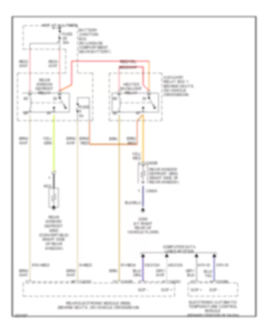
Defoggers Wiring Diagram for Ford Thunderbird 2005
 https://portal-diagnostov.com/license.html
Automotive Electricians Portal FZCO
Automotive Electricians Portal FZCO
https://portal-diagnostov.com/license.html
https://portal-diagnostov.com/license.html
Automotive Electricians Portal FZCO
Automotive Electricians Portal FZCOList of elements for Defoggers Wiring Diagram for Ford Thunderbird 2005:
- 4-eg12a
- 4-fa10
- 5-eg12a
- 5-fa10
- 9-hb23
- 91-hb24
- 91s-hb23
- Auxiliary relay box 1 (behind seats, on vehicle crossbeam)
- Battery junction box (in luggage compartment, near battery)
- C228b
- C402a
- C402b
- C420c
- C420e
- Computer data lines system
- Electronic automatic temperature control module (behind center of dash)
- Fuse 30a
- Fuse 5a
- G300 (at right rear of vehicle floor)
- Heated backlight relay
- Hot at all times
- Nca
- Rear electronic module (rem) (behind seats, on vehicle crossbeam)
- Rear window defrost grid (convertible) (right side of rear window)
- Rear window defrost grid (right side of rear window)
- Rear window defrost relay
- Scp +
- Scp -
ELECTRONIC POWER STEERING
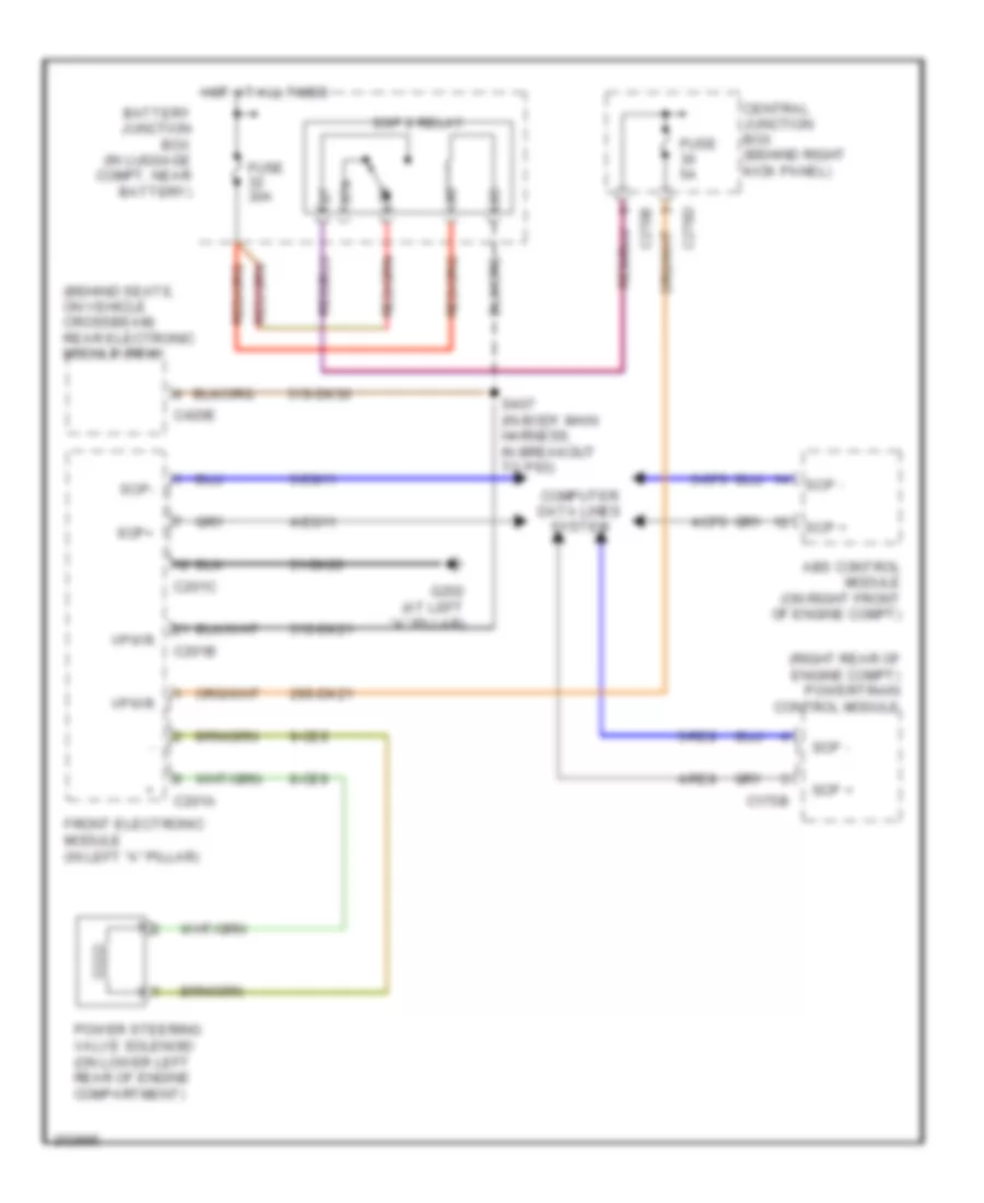
Electronic Power Steering Wiring Diagram for Ford Thunderbird 2005
 https://portal-diagnostov.com/license.html
Automotive Electricians Portal FZCO
Automotive Electricians Portal FZCO
https://portal-diagnostov.com/license.html
https://portal-diagnostov.com/license.html
Automotive Electricians Portal FZCO
Automotive Electricians Portal FZCOList of elements for Electronic Power Steering Wiring Diagram for Ford Thunderbird 2005:
- (behind seats, on vehicle crossbeam) rear electronic module (rem)
- (right rear of engine compt) powertrain control module
- 29s-dk21
- 31-dk20
- 31s-dk21
- 31s-dk30
- 4-cf6
- 4-eg11
- 4-re8
- 5-cf6
- 5-eg11
- 5-re8
- 8-ce9
- 87a
- 9-ce9
- Abs control module (on right front of engine compt)
- Battery junction box (in luggage compt, near battery)
- C175b
- C201a
- C201b
- C201c
- C270b
- C270d
- C420e
- Central junction box (behind right kick panel)
- Computer data lines system
- Front electronic module (in left "a" pillar)
- Fuse 30a
- Fuse 5a
- G202 (at left "a" pillar)
- Hot at all times
- Power steering valve solenoid (on lower left rear of engine compartment)
- S407 (in body main harness, in breakout to p93)
- Scp +
- Scp -
- Scp+
- Scp-
- Ssp 2 relay
- Vpwr
Power Steering Column Wiring Diagram for Ford Thunderbird 2005
 https://portal-diagnostov.com/license.html
Automotive Electricians Portal FZCO
Automotive Electricians Portal FZCO
https://portal-diagnostov.com/license.html
https://portal-diagnostov.com/license.html
Automotive Electricians Portal FZCO
Automotive Electricians Portal FZCOList of elements for Power Steering Column Wiring Diagram for Ford Thunderbird 2005:
- 29-al12
- 31-al11
- 32-al6
- 33-al6
- 34-al7
- 35-al7
- 7-al17
- 8-al10
- 8-al16
- 8-al17
- 9-al10
- 9-al17
- C220a
- C220c
- C270a
- Central junction box (behind right kick panel)
- Down
- Fuse 19 15a
- G203 (below right side of dash panel)
- Hot at all times
- In+ out-
- Instrument cluster
- Out
- Sig rtn
- Steering column position motor (on steering column)
- Steering column position sensor (on steering column)
- Steering column position switch
- Telescope
- Tilt
- Up- down+
- Vbatt
- Vref
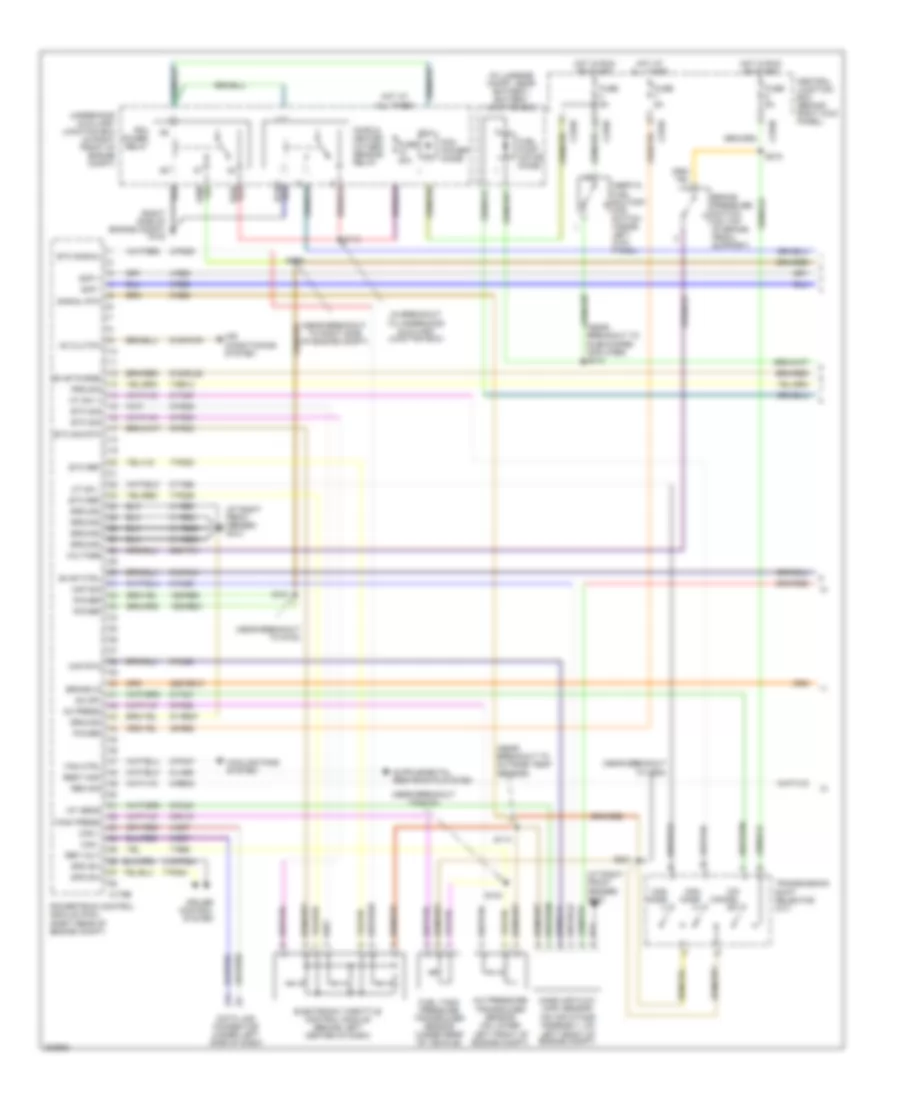
ENGINE PERFORMANCE
3.9L
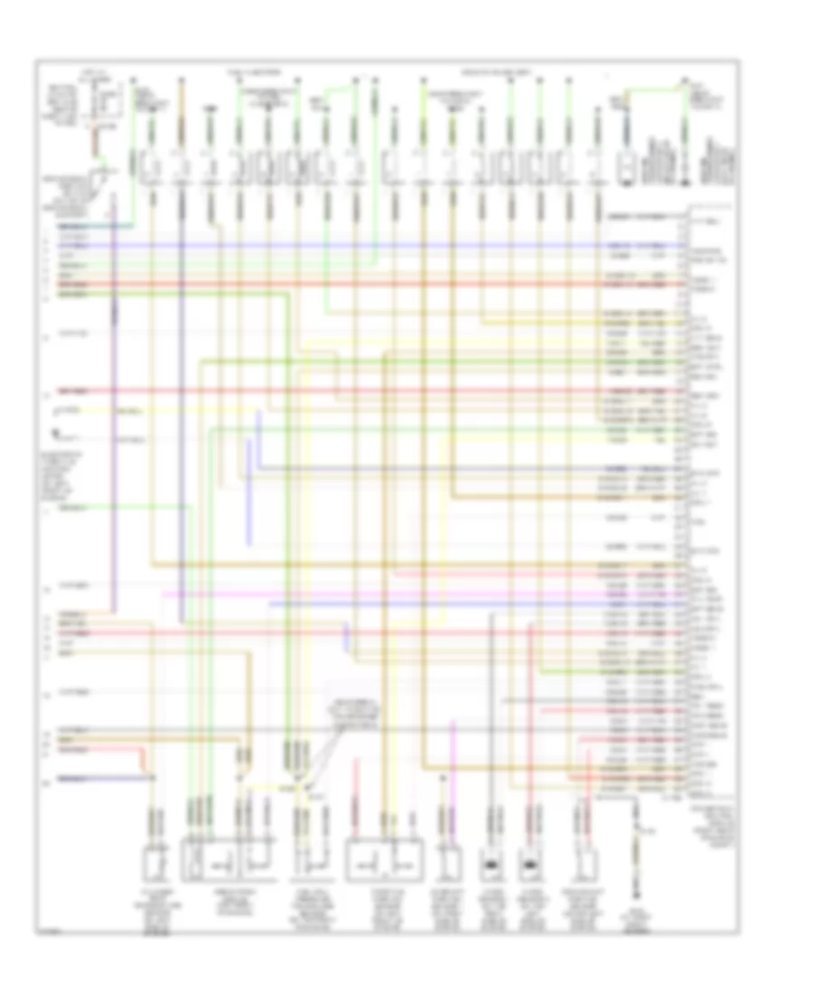
3.9L, Engine Performance Wiring Diagram (1 of 4) for Ford Thunderbird 2005
 https://portal-diagnostov.com/license.html
Automotive Electricians Portal FZCO
Automotive Electricians Portal FZCO
https://portal-diagnostov.com/license.html
https://portal-diagnostov.com/license.html
Automotive Electricians Portal FZCO
Automotive Electricians Portal FZCOList of elements for 3.9L, Engine Performance Wiring Diagram (1 of 4) for Ford Thunderbird 2005:
- (at right front fender) g103
- (in breakout to underhood auxiliary junction box)
- (in luggage compt, near battery) battery junction box
- (near breakout to c264)
- (near breakout to g103)
- (near breakout to outside temp sensor)
- (near breakout to right side of engine compt)
- (near breakout to subwoofer amplifier) s413
- (right side of engine compt) g102
- 15s-re21
- 15s-re8
- 29-re8
- 29s-pg1
- 29s-re13
- 31-re21
- 31-re25
- 31-re26
- 31-re8
- 31s-pg24
- 4-ec7
- 4-re8
- 5-ec7
- 5-re8
- 7-pg24
- 7-pg29
- 7-pg30
- 7-re14
- 7-re8
- 8-fa88
- 8-ja56
- 8-pa47
- 8-pg28
- 8-pg29
- 8-pg30
- 8-re32
- 8-rj13
- 8-rj22
- 8-rj40
- 8-ta21
- 8-ta67
- 8-ta68
- 9-pg30
- 9-re8
- 9-rj22
- 91-re27
- 91s-fa79
- 91s-rl25
- 91s-rl3
- A/c pressure transducer sensor (on lower left front of engine compt)
- Ac clutch
- Ac press
- Air conditioning system
- Brake in
- Brake pressure switch (on top of brake pedal support)
- C175b
- C270b
- C270d
- C270e
- Can +
- Can -
- Central junction box (behind right kick panel)
- Cooling fans system
- Cops & heated oxygen sensor relay
- Cruise control system
- Data link connector (under left side of dash)
- Electronic throttle control module (behind left center of dash)
- Etc ref
- Etc sig
- Etc sig rtn
- Etc signal
- Evap ctrl
- Evap purge
- Fan ctrl
- Fuel pump motor diode
- Fuel tank pressure transducer sensor (under rear of vehicle)
- Fuse 40a
- Fuse 5a
- Ground
- Hot at all times
- Hot in run or start
- Iat sens
- Inertia fuel shutoff (ifs) switch (inside left kick panel)
- Maf rtn
- Maf sig
- Man mode (+)
- Man mode (-)
- Mass air flow (maf) sensor (on air intake assembly, on left front of engine compt)
- Mt sw +
- Mt sw -
- O/d cancel sw
- Od off
- Pcm power diode
- Pcm power relay
- Power
- Powertrain control module (pcm) (right rear of engine compt)
- Prg sig
- Ref volt
- Rem sig
- Rest mod
- S101
- S104
- S109
- S113
- S114
- S218
- S221
- Scp +
- Scp -
- Signal rtn
- Spd sw
- Tank press
- Transmission shift selector (a/t)
- Underhood auxiliary junction box (in right front of engine compt)
- Voltage
3.9L, Engine Performance Wiring Diagram (2 of 4) for Ford Thunderbird 2005
 https://portal-diagnostov.com/license.html
Automotive Electricians Portal FZCO
Automotive Electricians Portal FZCO
https://portal-diagnostov.com/license.html
https://portal-diagnostov.com/license.html
Automotive Electricians Portal FZCO
Automotive Electricians Portal FZCOList of elements for 3.9L, Engine Performance Wiring Diagram (2 of 4) for Ford Thunderbird 2005:
- (front of engine compt) engine cooling fan motor
- (left side of transmission)
- (near breakout to turbine shaft speed sensor)
- (on left side of transmission) digital transmission range (dtr) sensor
- (under rear of vehicle)
- 8-rj25
- 8-rj26
- 8-ta26
- 8-ta27
- 8-ta37
- 8-ta38
- 8-ta39
- 8-ta40
- 8-ta51
- 8-ta74
- 9-ta1
- 91s-rj25
- 91s-rj26
- 91s-ta23
- 91s-ta24
- 91s-ta47
- 91s-ta63
- 91s-ta64
- 91s-ta65
- 91s-ta69
- 91s-ta70
- Automatic transmission
- Auxiliary junction box (underhood) (in right front of engine compt)
- C175t
- Evap canister purge valve (on left side of engine compt)
- Evap canister vent valve
- Fuse 15a
- H2os 12
- H2os 22
- Intermediate shaft speed (iss) sensor
- Iss
- Nca
- Oss
- Output shaft speed sensor
- P,2,1,3/4
- P,n,1
- P,r,2
- P,r,n,3/4
- Pcs a
- Pcs b
- Pcs c
- Power
- Powertrain control module (right rear of engine compt)
- Press ctrl sol a
- Press ctrl sol b
- Press ctrl sol c
- S102
- S107 (near breakout to windshield washer pump motor)
- S122
- S125 (near break- out to c139)
- Shift sol a
- Shift sol b
- Shift sol c
- Shift sol d
- Sig rtn
- Ss a
- Ss b
- Ss c
- Ss d
- Tcc sol
- Tft
- Tr1
- Tr2
- Tr3a
- Tr4
- Transmission fluid temperature sensor
- Tss
- Turbine shaft speed sensor (left front of transmission)
- Variable valve timing solenoids (sol 1: on right side of engine (sol 2: on left side of engine
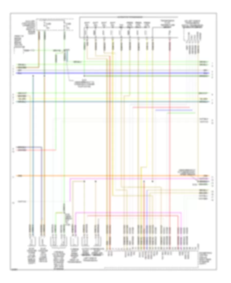
3.9L, Engine Performance Wiring Diagram (3 of 4) for Ford Thunderbird 2005
 https://portal-diagnostov.com/license.html
Automotive Electricians Portal FZCO
Automotive Electricians Portal FZCO
https://portal-diagnostov.com/license.html
https://portal-diagnostov.com/license.html
Automotive Electricians Portal FZCO
Automotive Electricians Portal FZCOList of elements for 3.9L, Engine Performance Wiring Diagram (3 of 4) for Ford Thunderbird 2005:
- (behind seats, on vehicle crossbeam) rear electronic module (rem)
- (near breakout to c139)
- (near breakout to defrost mode actuator)
- (near breakout to fuel tank pressure transducer sensor)
- (near breakout to g103) s100
- (near breakout to ho2s 22)
- 15-rp12b
- 15s-dk32
- 15s-rg2a
- 29s-cf58
- 29s-dk30
- 31s-rg2a
- 4-eg12a
- 5-eg12a
- 8-ga25
- 8-ga7
- 8-re32
- 9-ga1
- Abs control module (right front of engine compt)
- Air conditioning system
- Battery junction box (in luggage compt, near battery)
- C220b
- C270a
- C283b
- C283c
- C283d
- C420b
- C420c
- C420e
- C420f
- Camshaft position sensor 2 (on left side of engine)
- Central junction box (cjb) (behind right kick panel)
- Check engine ind
- Data link connector (under left side of dash)
- Engine oil temperature sensor (lower left front of engine)
- Fuel pump driver module (under rear of vehicle)
- Fuel pump relay
- Fuel rail temperature sensor (on right rear of engine)
- Fuel sender (under vehicle, in fuel tank)
- Fuse 10a
- Fuse 15a
- Fuse 5a
- G401 (right side of luggage compt)
- Generator
- Heated oxygen sensor 11 (near lower right rear of engine)
- Heated oxygen sensor 12 (in exhaust, rear of catalytic converter)
- Heated oxygen sensor 21 (near lower left rear of engine)
- Heated oxygen sensor 22 (in exhaust, rear of catalytic converter)
- Hot at all times
- Hot in start or run
- Instrument cluster
- Interior auxiliary junction box (under left side of dash)
- Microprocessor
- Nca
- Power steering pressure switch (on left side of engine compt)
- S111 (in dash panel to headlamp junction harness, in breakout to underhood auxiliary junction box)
- S123
- S132
- S206
- S207
- S414
- Scp +
- Scp -
- Underhood auxiliary junction box (in right front of engine compt)
- Vpwr
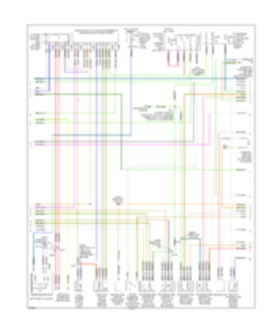
3.9L, Engine Performance Wiring Diagram (4 of 4) for Ford Thunderbird 2005
 https://portal-diagnostov.com/license.html
Automotive Electricians Portal FZCO
Automotive Electricians Portal FZCO
https://portal-diagnostov.com/license.html
https://portal-diagnostov.com/license.html
Automotive Electricians Portal FZCO
Automotive Electricians Portal FZCOList of elements for 3.9L, Engine Performance Wiring Diagram (4 of 4) for Ford Thunderbird 2005:
- (near break- out to ignition transformer capacitor 2)
- (near breakout to cop 8) s129
- (near breakout to fuel injector 8)
- 10-ba25
- 10-rj18
- 10-rj19
- 10-rj4
- 32-rg3
- 33-rg3
- 7-rj28
- 7-rn11
- 8-ba25
- 8-ce6
- 8-rj11
- 8-rj12
- 8-rj14
- 8-rj15
- 8-rj18
- 8-rj19
- 8-rj2
- 8-rj20
- 8-rj26
- 8-rj28
- 8-rj3
- 8-rj33
- 8-rj39
- 8-rj4
- 8-rj7
- 8-rl26
- 8-rl27
- 9-re1
- 9-rj28
- 91s-rj14
- 91s-rj15
- 91s-rl10
- 91s-rl11
- 91s-rl12
- 91s-rl13
- 91s-rl14
- 91s-rl15
- 91s-rl16
- 91s-rl17
- 91s-rl7
- 91s-rr10
- 91s-rr11
- 91s-rr12
- 91s-rr5
- 91s-rr6
- 91s-rr7
- 91s-rr8
- 91s-rr9
- Brake pedal position switch (on top of brake pedal support)
- C175e
- C270b
- Camshaft position sensor 1 (on right side of engine)
- Capacitor 1 transformer
- Capacitor 2 (in left rear
- Central junction box (cjb) (behind right kick panel)
- Ckp +
- Ckp -
- Cmp1 sens
- Cmp2 sens
- Coil 1
- Coil 2
- Coil 3
- Coil 4
- Coil 5
- Coil 6
- Coil 7
- Coil 8
- Coils on plugs (cop)
- Crankshaft position sensor (lower left side of engine)
- Cyl temp
- Cylinder head temperature sensor (on left side of engine)
- Dc volt
- Egr system module (top front of engine)
- Electronic throttle control motor (on left front of engine)
- Eot sig
- Ept ctrl
- Ept sens
- Ept sig
- Etc mtr
- Fuel injectors
- Fuel rail
- Fuel rail pressure transducer sensor (on top front of engine)
- Fuse 5a
- G103 (at right front fender)
- Gen
- Gen com
- Ho2s 11
- Ho2s 21
- Hot at all times
- Ignition
- Inj 1
- Inj 2
- Inj 3
- Inj 4
- Inj 5
- Inj 6
- Inj 7
- Inj 8
- Knock sensor 1 (on top right side of engine)
- Knock sensor 2 (on top left side of engine)
- Ks 1 feed
- Ks 1 rtn
- Ks 2 feed
- Ks 2 rtn
- Nca
- Of engine)
- Of engine) (left rear
- Powertrain control module (right rear of engine compt)
- Psp sw fd
- Ref volt
- Return
- S124
- S126
- S127
- S130
- S131 (near breakout to cop 4)
- S150 (near breakout to cmp 1)
- Temp sig
- Throttle position sensor (on left front of engine)
- Tps
- Tps rtn
- Tps sig
- Transformer ignition
- Vvt sol1
- Vvt sol2
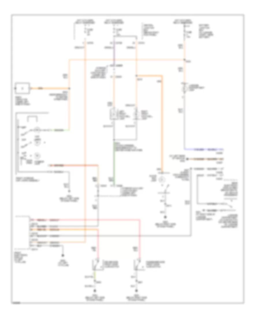
EXTERIOR LIGHTS
Back-up Lamps Wiring Diagram for Ford Thunderbird 2005
 https://portal-diagnostov.com/license.html
Automotive Electricians Portal FZCO
Automotive Electricians Portal FZCO
https://portal-diagnostov.com/license.html
https://portal-diagnostov.com/license.html
Automotive Electricians Portal FZCO
Automotive Electricians Portal FZCOList of elements for Back-up Lamps Wiring Diagram for Ford Thunderbird 2005:
- 3/4
- 30-dk31
- 31-aj71
- 31-dk30d
- 31-dk30e
- 31-dk30f
- 31-dk30g
- 31-dk30h
- 31-re21
- 31-re25
- 31-re26
- 31-re8
- 31s-lg16
- 31s-lg9
- 4-eg12a
- 4-re8
- 5-eg12a
- 5-re8
- 8-ta37
- 8-ta38
- 8-ta39
- 8-ta40
- 9-ta1
- 91-re27
- Battery junction box (in luggage compt, near battery)
- C175b
- C175t
- C420a
- C420c
- C420d
- C420e
- C420f
- Computer data lines system
- Digital transmission range (dtr) sensor (on left side of transmission)
- Fuse 10a
- Fuse 5a
- G103 (at right front fender)
- G402 (at left rear of vehicle)
- Hot at all times
- Hot w/ ssp 3 relay energized
- Left reversing lamp
- N n
- Powertrain control module (right rear of engine compt)
- Rear electronic module (rem) (behind seats, on vehicle crossbeam)
- Right reversing lamp
- S122 (in transmission control selector neutral switch harness, near breakout to turbine shaft speed sensor)
- S409
Exterior Lamps Wiring Diagram (1 of 2) for Ford Thunderbird 2005
 https://portal-diagnostov.com/license.html
Automotive Electricians Portal FZCO
Automotive Electricians Portal FZCO
https://portal-diagnostov.com/license.html
https://portal-diagnostov.com/license.html
Automotive Electricians Portal FZCO
Automotive Electricians Portal FZCOList of elements for Exterior Lamps Wiring Diagram (1 of 2) for Ford Thunderbird 2005:
- 29-dk20
- 31-dk20
- 31-dk20a
- 31-dk20b
- 31-dk20c
- 31-dk20d
- 31s-ld9
- 31s-lf16
- 31s-lf17
- 31s-lf7
- 31s-lf8
- 31s-lg11
- 31s-lg18
- 4-eg11
- 5-eg11
- Brake pedal position switch (on top of brake pedal support)
- C201a
- C201b
- C201c
- C220b
- C220c
- C270b
- C270d
- C270e
- Central junction box (behind right kick panel)
- Computer data lines system
- Front electronic module (in left "a" pillar)
- Fuse 10a
- Fuse 5a
- G202 (at left "a" pillar)
- Hazard
- Hot at all times
- Hot w/ ssp 1 relay energized
- Instrument cluster
- Left
- Left driving lamp
- Left front park/ turn lamp
- Left front side lamp
- Left turn ind
- Low beam
- Main light switch
- Microprocessor
- Multi- function switch
- Off
- Park
- Right
- Right driving lamp
- Right front park/ turn lamp
- Right front side lamp
- Right turn ind
- S100 (in dash panel to headlamp junction harness, near breakout to g103)
- S116 (in dash panel to headlamp junction
- S118
- Underhood auxiliary junction box (in right front of engine compt)
Exterior Lamps Wiring Diagram (2 of 2) for Ford Thunderbird 2005
 https://portal-diagnostov.com/license.html
Automotive Electricians Portal FZCO
Automotive Electricians Portal FZCO
https://portal-diagnostov.com/license.html
https://portal-diagnostov.com/license.html
Automotive Electricians Portal FZCO
Automotive Electricians Portal FZCOList of elements for Exterior Lamps Wiring Diagram (2 of 2) for Ford Thunderbird 2005:
- 29s-dk30
- 30-dk31
- 31-dk30d
- 31-dk30e
- 31-dk30f
- 31-dk30g
- 31-dk30h
- 31s-lf10
- 31s-lf11
- 31s-lf19
- 31s-lf20
- 31s-lf21
- 31s-lg14
- 31s-lg21
- 31s-lg6
- 4-eg12a
- 5-eg12a
- Battery junction box (in luggage compt, near battery)
- C420b
- C420c
- C420d
- C420e
- C420f
- Computer data lines system
- Fuse 10a
- Fuse 5a
- G402 (at left rear of vehicle)
- High mounted stoplamp
- Hot at all times
- Hot w/ ssp 3 relay energized
- Hot w/ ssp 4 relay energized
- Left rear lamp assembly
- Left rear side lamp
- License lamp
- Nca
- Rear electronic module (rem) (behind seats, on vehicle crossbeam)
- Right rear lamp assembly
- Right rear side lamp
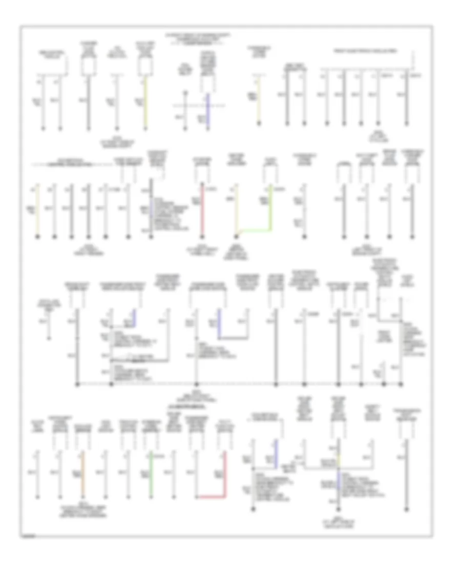
GROUND DISTRIBUTION
Ground Distribution Wiring Diagram (1 of 2) for Ford Thunderbird 2005
 https://portal-diagnostov.com/license.html
Automotive Electricians Portal FZCO
Automotive Electricians Portal FZCO
https://portal-diagnostov.com/license.html
https://portal-diagnostov.com/license.html
Automotive Electricians Portal FZCO
Automotive Electricians Portal FZCOList of elements for Ground Distribution Wiring Diagram (1 of 2) for Ford Thunderbird 2005:
- (in right front of engine compt) underhood auxiliary junction box
- A/c clutch field coil
- Abs control module
- Abs test connector
- Anti-theft hood switch
- Audio unit
- Audio unit shield
- Automatic temperature control module)
- Auxiliary coolant pump motor
- Brake fluid level switch
- Brake shift interlock
- C175b
- C197c
- C201a
- C201c
- C218a
- C220a
- C228b
- C240a
- Camshaft position sensor shield
- Center image amplifier
- Convertible top switch
- Cops & heated oxygen sensor (ho2s) relay
- Data link connector (dlc)
- Driver side front heated seat module
- Driver side front seat adjust switch
- Driver side seat heater switch
- Electronic automatic temperature control (eatc) module
- Electronic automatic temperature control (eatc) module shield
- Front cigar lighter
- Front electronic module (fem)
- G101 (left front of engine compt)
- G102 (at right side of engine compt)
- G103 (at right front fender)
- G104 (at right front wheelwell)
- G200 (behind center of dash panel)
- G202 (at left ``a" pillar)
- G203 (below right side of dash panel)
- G301 (at left side of vehicle floor)
- Glove box lamp
- Heater blower control module
- Horn
- Instrument cluster
- Instrument panel dimming module
- Main light switch
- Mass air flow (maf) sensor
- Multi- function switch
- Nca
- Passenger side door lock switch
- Passenger side front door ajar switch
- Passenger side front heated seat module
- Passenger side front seat adjust switch
- Passenger side seat heater switch
- Pcm power relay
- Power point
- Powertrain control module (pcm)
- S124 (in engine control sensor & fuel charge harness, in breakout to powertrain control module)
- S214 (in main harness, near breakout to right center image speaker)
- S222 (in main harness, near breakout to defrost mode actuator)
- S300 (in seat back control harness, in breakout to c311)
- S301 (in seat back control harness, in breakout to driver side front seat adjust switch)
- S303 (in power seats harness, near breakout to c327)
- S601 (in body main harness, near breakout to c610)
- Safety belt buckle switch
- Starter motor
- Steering wheel assembly
- Sunload sensor
- Traction control switch
- Transmission shift selector
- W/ heated seats
- Washer fluid level switch
- Windshield washer pump motor
- Windshield wiper motor
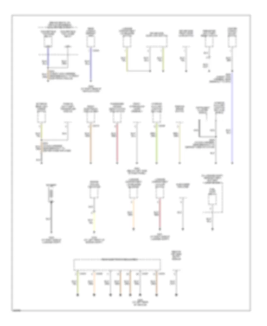
Ground Distribution Wiring Diagram (2 of 2) for Ford Thunderbird 2005
 https://portal-diagnostov.com/license.html
Automotive Electricians Portal FZCO
Automotive Electricians Portal FZCO
https://portal-diagnostov.com/license.html
https://portal-diagnostov.com/license.html
Automotive Electricians Portal FZCO
Automotive Electricians Portal FZCOList of elements for Ground Distribution Wiring Diagram (2 of 2) for Ford Thunderbird 2005:
- (behind seats, on vehicle crossbeam) auxiliary relay box 1
- (in luggage compt, near battery) battery junction box
- 87a
- Battery
- C201g
- C283b
- C402a
- C420a
- C420c
- C420e
- C420f
- Convertible top lower relay
- Convertible top raise relay
- Driver side door lock switch
- Driver side front door ajar switch
- Engine cooling fan motor
- Exterior rear view mirror switch
- Front electronic module (fem)
- Front interior/map lamps assembly
- Fuel pump relay
- G105 (at left front of engine compt)
- G204 (below left side of dash panel)
- G300 (at right rear of vehicle floor)
- G401 (at right side of luggage compt)
- G402 (at left rear of vehicle)
- G403 (at right side of luggage compt)
- Instrument cluster shield
- Interior auxiliary junction box (ajb)
- Interior auxiliary junction box (ajb) shield
- Luggage compartment lid ajar switch
- Luggage compartment lid release solenoid
- Luggage compartment lid release switch
- Master window adjust switch
- Nca
- Near breakout to center image amplifier)
- Near breakout to front electronic module)
- Parking brake switch
- Passenger air bag deactivation (pad) switch
- Passive anti-theft transceiver module
- Perimeter anti-theft reset switch
- Rear electronic module (rem)
- Rear window defrost grid
- Remote keyless entry module
- S205 (in main harness, near breakout to defrost mode actuator)
- S500 (in body main harness, near breakout to c510)
- Subwoofer amplifier
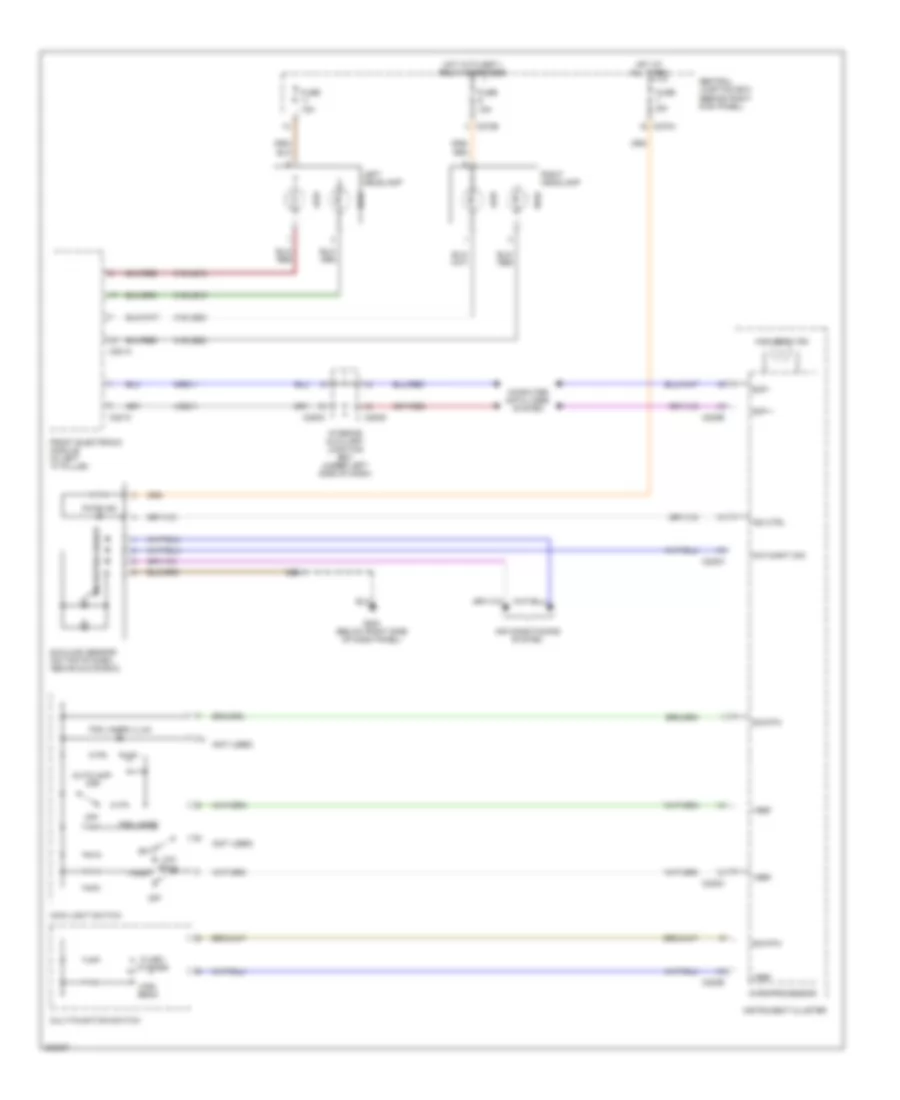
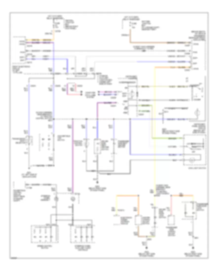
HEADLIGHTS
Headlights Wiring Diagram for Ford Thunderbird 2005
 https://portal-diagnostov.com/license.html
Automotive Electricians Portal FZCO
Automotive Electricians Portal FZCO
https://portal-diagnostov.com/license.html
https://portal-diagnostov.com/license.html
Automotive Electricians Portal FZCO
Automotive Electricians Portal FZCOList of elements for Headlights Wiring Diagram for Ford Thunderbird 2005:
- (not used)
- 15a
- 31s-le15
- 31s-le16
- 31s-le22
- 31s-le23
- 4-eg11
- 5-eg11
- Air conditioning system
- Autolamp on
- C201a
- C201c
- C220a
- C220b
- C220c
- C270a
- C270e
- C283c
- C283d
- Central junction box (behind right kick panel)
- Computer data lines system
- Day/night sig
- Flash to pass
- Fog lamps
- Fog lamps illum
- Front electronic module (in left "a" pillar)
- Fuse
- Fuse 5a
- G203 (below right side of dash panel)
- High
- High beam
- High beam ind
- Hot at all times
- Hot with ssp 1 relay energized
- Ind ctrl
- Instrument cluster
- Interior auxiliary junction box (under left side of dash)
- Left headlamp
- Low
- Low beam
- Main light switch
- Microprocessor
- Multi-function switch
- Off
- Park
- Pats ind
- Right headlamp
- S214
- Scp +
- Scp -
- Sig rtn
- Sunload sensor (on top of dash, above glove box)
- Vref
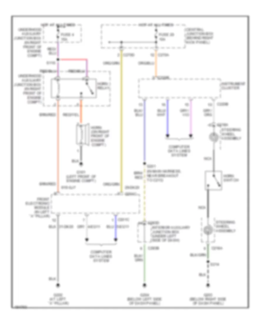
HORN
Horn Wiring Diagram for Ford Thunderbird 2005
 https://portal-diagnostov.com/license.html
Automotive Electricians Portal FZCO
Automotive Electricians Portal FZCO
https://portal-diagnostov.com/license.html
https://portal-diagnostov.com/license.html
Automotive Electricians Portal FZCO
Automotive Electricians Portal FZCOList of elements for Horn Wiring Diagram for Ford Thunderbird 2005:
- 10a
- 15a
- 29-dk20
- 91s-gj7
- C201c
- C218a
- C220b
- C270a
- C270d
- C283b
- C283d
- Central junction box (behind right kick panel)
- Computer data lines system
- Front electronic module (in left ``a" pillar)
- Fuse 20
- Fuse 4
- G101 (left front of engine compt)
- G202 (at left ``a" pillar)
- G203 (below right side of dash panel)
- G204 (below left side of dash panel)
- Horn switch
- Horn (on right front of engine compt)
- Horn relay
- Hot at all times
- Instrument cluster
- Interior auxiliary junction box (under left side of dash)
- Nca
- Near breakout to c213)
- S110
- S201
- S214
- Steering wheel assembly
- Underhood auxiliary junction box (in right front of engine compt)
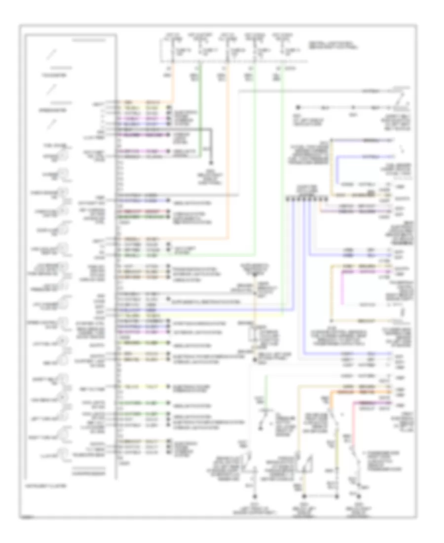
INSTRUMENT CLUSTER
Instrument Cluster Wiring Diagram for Ford Thunderbird 2005
 https://portal-diagnostov.com/license.html
Automotive Electricians Portal FZCO
Automotive Electricians Portal FZCO
https://portal-diagnostov.com/license.html
https://portal-diagnostov.com/license.html
Automotive Electricians Portal FZCO
Automotive Electricians Portal FZCOList of elements for Instrument Cluster Wiring Diagram for Ford Thunderbird 2005:
- (below left side of dash panel) g204
- (in engine control sensor & fuel charge harness, near breakout to ignition transformer capacitor 2)
- (near
- +/-
- 10-gj9
- 10-gl36
- 10-gl6
- 15-gg1
- 15-ja14a
- 29-al12
- 29-gg11
- 30s-gl46
- 30s-gl47
- 30s-gm7
- 31-al11
- 31s-bb12
- 31s-ja14a
- 32-al6
- 33-al6
- 34-al7
- 35-al7
- 4-eg11
- 4-eg12a
- 4-eg8
- 4-re8
- 5-eg11
- 5-eg12a
- 5-eg8
- 5-re8
- 64s-lk29
- 7-al17
- 75-gg15
- 8-al10
- 8-al16
- 8-al17
- 8-ga25
- 8-gc21
- 8-gc7
- 8-ge52
- 8-gl36
- 8-ja13
- 8-le10
- 8-le14
- 8-le21
- 8-le42
- 8-le47
- 8-lg43
- 8-rj33
- 8-ta34
- 9-al10
- 9-al17
- 9-ga1
- 9-le10
- 9-le29
- 9-lg43
- 9-re1
- 9-rp9
- 91-gg11
- Abs ind
- Air bag ind
- Air bag ind ctrl
- Anti-theft ind, ctrl vpwr
- Anti-theft system
- Beam sens sig hazard, turn sig sw sns sig
- Brake fluid level switch (on left rear of engine compt, on brake fluid reservoir)
- Breakout to c213) s201
- C175b
- C175e
- C201c
- C201d
- C201e
- C220a
- C220b
- C220c
- C270a
- C420c
- C420e
- C420f
- Central junction box (behind right kick panel)
- Charge ind
- Check engine ind
- Check fuel cap ind
- Chime
- Computer data lines system
- Courtesy lamp sw sns
- Cylinder head temperature sensor (on left side of engine)
- Day/night sig
- Door ajar ind
- Driver side front door ajar switch (rear of driver door)
- Electronic power steering system
- Exterior lights system
- Front electronic module (in left "a" pillar)
- Fuel gauge
- Fuel sender (under vehicle, in fuel tank)
- Fuse 13 5a
- Fuse 17 5a
- Fuse 19 15a
- Fuse 20 10a
- Fuse 4 5a
- G101 (left front of engine compartment.)
- G203 (below right side of dash panel)
- G204 (below left side of dash panel)
- G301 (at left side of vehicle floor)
- Gnd
- Headlights system
- High beam ind
- High coolant temp ind
- Horn sw sns
- Horns system
- Hot at all times
- Hot in run or acc
- Hot in run or start
- Hot in start or run
- Illum dimmer sw sns
- Illum ind
- Illum, feed
- Instrument cluster
- Interior auxiliary junction box (ajb)
- Interior lights system
- Key warning sw sns
- Left turn ind
- Low brake fluid level/ park brake ind
- Low fuel ind
- Low oil pressure ind
- Low washer fluid ind
- Main lights sw sig
- Microprocessor
- Oil pressure switch (on lower front of engine)
- Park sw sns sig rtn sig
- Parking brake switch (at base of parking brake assembly, in center console)
- Passenger side front door ajar switch (rear of passenger door)
- Powertrain control module (right rear of engine compt)
- Rear electronic module (rem) (behind seats, on vehicle crossbeam)
- Ref volt
- Ref voltage
- Right turn ind
- S126
- S301
- S414 (in fuel tank gauge sender harness, near breakout to fuel tank pressure transducer sensor)
- S500
- S601
- Safety belt buckle switch (in left seat belt buckle)
- Safety belt ind
- Scp+
- Scp-
- Sig rtn
- Sig rtn
- Speed control on ind
- Speedometer
- Starter, ctrl
- Starting/charging system
- Tachometer
- Telescope sens
- Tilt sens
- Transmissions system
- Vbatt
- Vpwr
- Vref
INTERIOR LIGHTS
Courtesy Lamps Wiring Diagram for Ford Thunderbird 2005
 https://portal-diagnostov.com/license.html
Automotive Electricians Portal FZCO
Automotive Electricians Portal FZCO
https://portal-diagnostov.com/license.html
https://portal-diagnostov.com/license.html
Automotive Electricians Portal FZCO
Automotive Electricians Portal FZCOList of elements for Courtesy Lamps Wiring Diagram for Ford Thunderbird 2005:
- (at left rear of vehicle) g402
- 29s-dk21
- 30s-gl46
- 30s-gl47
- 31-dk20a
- 31-dk30e
- 31-lc10
- 31s-dk21
- 31s-dk30
- 31s-lb25
- 8-gl20
- Battery junction box (in luggage compt, near battery)
- C201a
- C201b
- C201d
- C201e
- C270a
- C270b
- C270d
- C283a
- C283b
- C283d
- C420b
- C420c
- C420e
- C420f
- Central junction box (behind right kick panel)
- Door open
- Driver side front door ajar switch
- Front electronic module (in left ``a" pillar)
- Front interior/ map lamps assembly
- Fuse 10a
- Fuse 5a
- G202 (at left ``a" pillar)
- G203 (below right side of dash panel)
- G204 (below left side of dash panel)
- G401 (at right side of luggage compartment)
- Glove box lamp
- Hot with ssp2 relay energized
- Hot with ssp4 relay energized
- Interior auxiliary junction box (under left side of dash)
- Interior lamp
- Lamps
- Left front footwell lamp
- Luggage compartment lamp
- Luggage compartment lid ajar switch (on center rear of luggage compartment)
- Map
- Off
- Passenger side front door ajar switch
- Radio capacitor (under left side of dash)
- Rear electronic module (rem) (behind seats, on vehicle crossbeam)
- Right front footwell lamp
- S204 (in main harness, near breakout to center image amplifier)
- S214
- S215
- S233 (near breakout to heated wiper park)
- S400
- S407 (in body main harness, in breakout to p93)
- S500
- S601
Instrument Illumination Wiring Diagram for Ford Thunderbird 2005
 https://portal-diagnostov.com/license.html
Automotive Electricians Portal FZCO
Automotive Electricians Portal FZCO
https://portal-diagnostov.com/license.html
https://portal-diagnostov.com/license.html
Automotive Electricians Portal FZCO
Automotive Electricians Portal FZCOList of elements for Instrument Illumination Wiring Diagram for Ford Thunderbird 2005:
- (behind seats, on vehicle crossbeam) rear electronic module (rem)
- (in body main harness, in breakout to p93) s407
- (in body main harness, near breakout to central junction box) s220
- (in main harness, near breakout to traction control switch) s200
- 29s-dk22
- 29s-dk31
- 31-le10
- 31s-dk21
- 31s-dk30
- 31s-pg24
- 4-eg11
- 4-eg12a
- 5-eg11
- 5-eg12a
- 64s-le10
- 64s-lh2
- 7-lh1
- 8-le10
- 9-le10
- Battery junction box (in luggage compt, near battery)
- C175b
- C201b
- C201c
- C201e
- C218a
- C220a
- C220b
- C220c
- C270b
- C283a
- C283b
- C283c
- C283d
- C420c
- C420e
- C420f
- Central junction box (behind right kick panel)
- Computer
- Convertible top switch
- Courtesy
- Data lines system
- Dimmer
- Driver side door lock switch
- Driver side seat heater
- Electronic hidden antenna module
- Front electronic module (in left ``a" pillar)
- Fuse 10a
- Fuse 15a
- G203 (below right side of dash panel)
- G204 (below left side of dash panel)
- G301 (at left side of vehicle floor)
- Hot with ssp2
- Hot with ssp4
- Ill
- Illum
- Instrument cluster
- Instrument panel dimming module (behind left side of dash)
- Interior auxiliary junction box (under left side of dash)
- Low beam
- Main light switch
- Master window adjust switch
- Microprocessor
- Nca
- Off
- Park
- Passenger side door lock switch
- Passenger side seat heater switch
- Passenger side window adjust switch
- Powertrain control module (right rear of engine compt)
- Pwr
- Relay energized
- S214
- S230
- S500
- S601
- Scp+
- Scp-
- Sig
- Sig rtn
- Speed control switch
- Steering wheel assembly
- Steering wheel auxiliary audio controls
- Switch
- Traction control switch
- Transmission shift selector
- Vpwr
- Vref
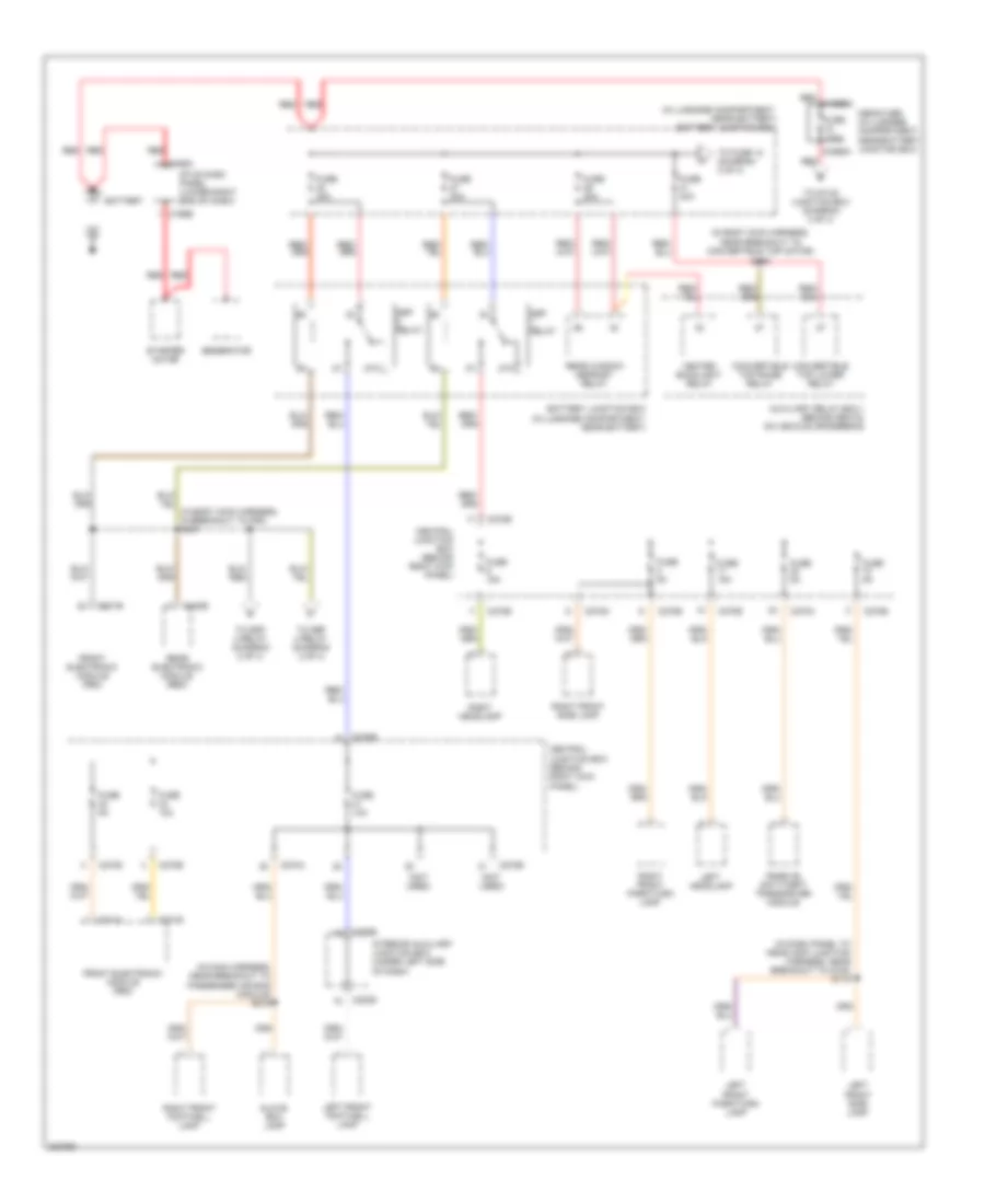
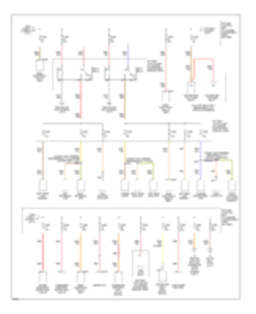
POWER DISTRIBUTION
Power Distribution Wiring Diagram (1 of 4) for Ford Thunderbird 2005
 https://portal-diagnostov.com/license.html
Automotive Electricians Portal FZCO
Automotive Electricians Portal FZCO
https://portal-diagnostov.com/license.html
https://portal-diagnostov.com/license.html
Automotive Electricians Portal FZCO
Automotive Electricians Portal FZCOList of elements for Power Distribution Wiring Diagram (1 of 4) for Ford Thunderbird 2005:
- (in body main harness, near breakout to convertible top motor) s405
- (in dash panel to headlamp junction harness, near breakout to g105) s118
- (in luggage compartment, near battery) battery junction box
- (in main harness, near breakout to passenger air bag module) s215
- (not used)
- 87a
- Auxiliary relay box 1 (behind seats, on vehicle crossbeam)
- Battery
- Battery junction box (in luggage compartment, near battery)
- C195a
- C195b
- C201a
- C201b
- C201e
- C270a
- C270b
- C270d
- C270e
- C283b
- C283d
- C4066a
- C420e
- Central junction box (behind right kick panel)
- Convertible top lower relay
- Convertible top raise relay
- Front electronic module (fem)
- Fuse 10a
- Fuse 15a
- Fuse 175a
- Fuse 30a
- Fuse 40a
- Fuse 5a
- Generator
- Glove box lamp
- Heated backlight relay
- Interior auxiliary junction box (under left side of dash)
- Left front footwell lamp
- Left front park/turn lamp
- Left front side lamp
- Left headlamp
- Mega fuse (in luggage compartment, near battery junction box)
- Passive anti-theft transceiver module
- Rear electronic module (rem)
- Rear window defrost relay
- Red
- Red c4066c
- Right front footwell lamp
- Right front park/turn lamp
- Right front side lamp
- Right headlamp
- Ssp relay
- Starter motor
- Stud dash panel (lower right end of dash)
- To fuse 12 (diagram 2 of 4)
- To ssp 3 relay (diagram 2 of 4)
- To ssp 4 relay (diagram 2 of 4)
- To stud junction box (diagram 3 of 4)
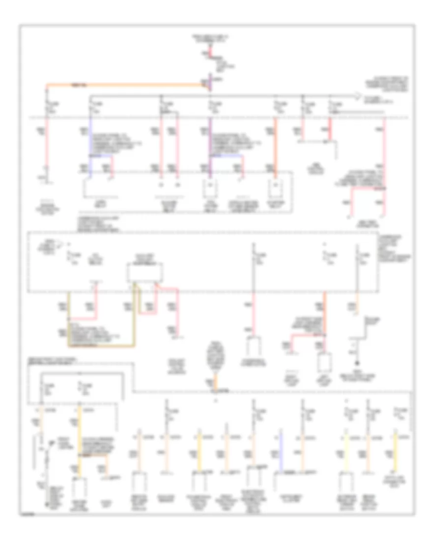
Power Distribution Wiring Diagram (2 of 4) for Ford Thunderbird 2005
 https://portal-diagnostov.com/license.html
Automotive Electricians Portal FZCO
Automotive Electricians Portal FZCO
https://portal-diagnostov.com/license.html
https://portal-diagnostov.com/license.html
Automotive Electricians Portal FZCO
Automotive Electricians Portal FZCOList of elements for Power Distribution Wiring Diagram (2 of 4) for Ford Thunderbird 2005:
- (in body main harness, near breakout to c405) s402
- (in body main harness, near breakout to heated wiper park) s233
- (in body main harness, near breakout to luggage compartment lamp) s409
- 87a
- Auxiliary relay box 1 (behind seats, on vehicle crossbeam)
- Battery junction box (in luggage compartment, near battery)
- C102a
- C201g
- C420a
- C420e
- C420f
- Convertible top lower relay
- Convertible top raise relay
- Driver side front heated seat module
- Driver side front seat adjust switch
- From fuse 14 (diagram 2 of 4)
- From fuse 31 (diagram 1 of 4)
- From splice s407 (diagram 1 of 4)
- Front electronic module (fem)
- Front interior/ map lamps assembly
- Fuel pump relay
- Fuse 10a
- Fuse 15a
- Fuse 20a
- Fuse 30a
- Fuse 40a
- Fuse 5a
- Generator
- High mounted stoplamp
- Left rear lamp assembly
- Left rear side lamp
- Left reversing lamp
- License lamps
- Luggage compartment lamp
- Nca
- Passenger side front heated seat module
- Passenger side front seat adjust switch
- Radio capacitor
- Rear electronic module (rem)
- Red
- Right rear lamp assembly
- Right rear side lamp
- Right reversing lamp
- S400
- Ssp 3 relay
- Ssp 4 relay
- Subwoofer amplifier
- To central junction box (cjb) (connector c270b, pin 10) (diagram 3 of 4)
- To fuse 11 (diagram 2 of 4)
- To splice s211 (page 4 of 4)
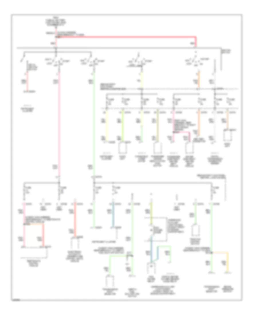
Power Distribution Wiring Diagram (3 of 4) for Ford Thunderbird 2005
 https://portal-diagnostov.com/license.html
Automotive Electricians Portal FZCO
Automotive Electricians Portal FZCO
https://portal-diagnostov.com/license.html
https://portal-diagnostov.com/license.html
Automotive Electricians Portal FZCO
Automotive Electricians Portal FZCOList of elements for Power Distribution Wiring Diagram (3 of 4) for Ford Thunderbird 2005:
- (behind right kick panel) central junction box
- (below right side of dash panel) g203
- (in dash panel to headlamp junction harness, in breakout to abs test connector) s120
- (in dash panel to headlamp junction harness, in breakout to underhood auxiliary junction box) s110
- (in front side lamp harness, near breakout for c133) s117
- (in main harness, near breakout to right center image speaker) s208
- (in right front of engine compartment) underhood auxiliary junction box
- A/c clutch relay
- Abs control module
- Abs test connector
- Audio unit
- Auxiliary coolant pump relay
- Blower motor relay
- Brake pedal position switch
- C175b
- C201c
- C220a
- C220b
- C228b
- C240a
- C265b
- C270a
- C270b
- C270c
- C270d
- Center image amplifier
- Coolant control valve solenoid
- Cops & heated oxygen sensor (ho2s) relay
- Data link connector (dlc)
- Electronic automatic temperature control (eatc) module
- Engine cooling fan motor
- Exterior rear view mirror switch
- From fuse 14 h (diagram 3 of 4)
- From fuse 25 battery junction box (bjb) (diagram 2 of 4)
- From mega fuse 18 (diagram 1 of 4)
- Front cigar lighter
- Front electronic module (fem)
- Fuse 10a
- Fuse 15a
- Fuse 20a
- Fuse 30a
- Fuse 40a
- Fuse 5a
- Fuse 60a
- G203 (below right side of dash panel)
- Horn relay
- Instrument cluster
- Left driving lamp
- Nca
- Off
- Pcm power relay
- Power point
- Powertrain control module (pcm)
- Red
- Remote keyless entry module
- Right driving lamp
- S112 (in dash panel to headlamp junction harness, in breakout to underhood auxiliary junction box)
- Starter relay
- Stud junction box
- Sunload sensor
- To fuse 1 (diagram 3 of 4)
- Underhood auxiliary junction box (in right front of engine compartment)
- Windshield wiper motor
Power Distribution Wiring Diagram (4 of 4) for Ford Thunderbird 2005
 https://portal-diagnostov.com/license.html
Automotive Electricians Portal FZCO
Automotive Electricians Portal FZCO
https://portal-diagnostov.com/license.html
https://portal-diagnostov.com/license.html
Automotive Electricians Portal FZCO
Automotive Electricians Portal FZCOList of elements for Power Distribution Wiring Diagram (4 of 4) for Ford Thunderbird 2005:
- (a/t)
- (behind right kick panel) central junction box
- (in body main harness, near breakout to g204) s218
- (in body main harness, near breakout to inertia fuel shut-off switch)
- (in body main harness, near breakout to restraints control module) s302
- (not used)
- A/t
- Abs test connector
- Acc
- Audio unit
- Brake pressure switch
- C220a
- C220b
- C228b
- C240a
- C270a
- C270b
- C270c
- C270d
- C270e
- C310a
- Cops & heated oxygen sensor (ho2s) relay
- Digital transmission range (dtr) sensor
- Driver side front heated seat module
- Electronic automatic temperature control (eatc) module
- From fuse 22, battery junction box (bjb) (diagram 2 of 4)
- Fuse 10a
- Fuse 3a
- Fuse 5a
- Ignition switch
- Inertia fuel shutoff (ifs) switch
- Instrument cluster
- Key-in ignition switch
- Lock
- Near breakout to g200) s211
- Off
- Passenger air bag deactivation (pad) switch
- Passenger side front heated seat module
- Pcm power diode
- Pcm power relay
- Red
- Restraints control module
- S216
- Start
- Traction control switch
- Transmission shift selector
- Underhood auxiliary junction box (in right front of engine compartment)
- Windshield wiper motor
POWER DOOR LOCKS
Power Door Locks Wiring Diagram for Ford Thunderbird 2005
 https://portal-diagnostov.com/license.html
Automotive Electricians Portal FZCO
Automotive Electricians Portal FZCO
https://portal-diagnostov.com/license.html
https://portal-diagnostov.com/license.html
Automotive Electricians Portal FZCO
Automotive Electricians Portal FZCOList of elements for Power Door Locks Wiring Diagram for Ford Thunderbird 2005:
- (behind right kick panel)
- (on center rear of luggage compt)
- (rear of passenger door)
- 29-aa17
- 29s-aa83
- 29s-dk21
- 29s-dk31
- 30-aa79
- 30s-gl46
- 30s-gl47
- 31-aa17
- 32-aa11
- 32-aa21
- 33-aa10
- 33-aa20
- 4-eg11
- 4-eg12a
- 4-eg13a
- 5-eg11
- 5-eg12a
- 5-eg13a
- 8-aa10
- 8-aa11
- 8-aa20
- 8-aa21
- 8-aa30a
- 8-gl20
- 8-gl7
- 91s-gj7
- Anti-theft hood switch (on top left front of engine compt)
- Battery junction box (in luggage compt, near battery)
- C201a
- C201c
- C201d
- C201e
- C270b
- C270d
- C420b
- C420c
- C420e
- C420f
- Central junction box
- Computer data lines system
- Driver side door lock switch
- Driver side front door ajar switch (rear of driver door)
- Driver side front door lock unit (rear of driver door)
- Front electronic module (in left "a" pillar)
- Fuse 15a
- Fuse 5a
- G101 (left front of engine compt)
- G203 (below right side of dash panel)
- G204 (below left side of dash panel)
- G401 (at right side of luggage compt)
- G402 (at left rear of vehicle)
- Gnd
- Horn (on right front of engine compt)
- Horn relay
- Hot at all times
- Hot w/ ssp 2 relay energized
- Hot w/ ssp 4 relay energized
- Interior lights system
- Lock
- Luggage compartment lid ajar switch (on center rear of luggage compt)
- Luggage compartment lid release solenoid
- Luggage compartment lid release switch
- Passenger side door lock switch
- Passenger side front door ajar switch (rear of passenger door)
- Passenger side front door lock unit
- Perimeter anti-theft reset switch
- Pwr
- Rear electronic module (rem) (behind seats, on vehicle crossbeam)
- Remote keyless entry module (behind seats, on vehicle crossbeam)
- S110
- S500
- S601
- Scp +
- Scp -
- Sens sig
- Sw gnd
- Underhood auxiliary junction box (in right front of engine compt)
- Unlock
- Vbatt
- Vpwr
- Vref
POWER MIRRORS
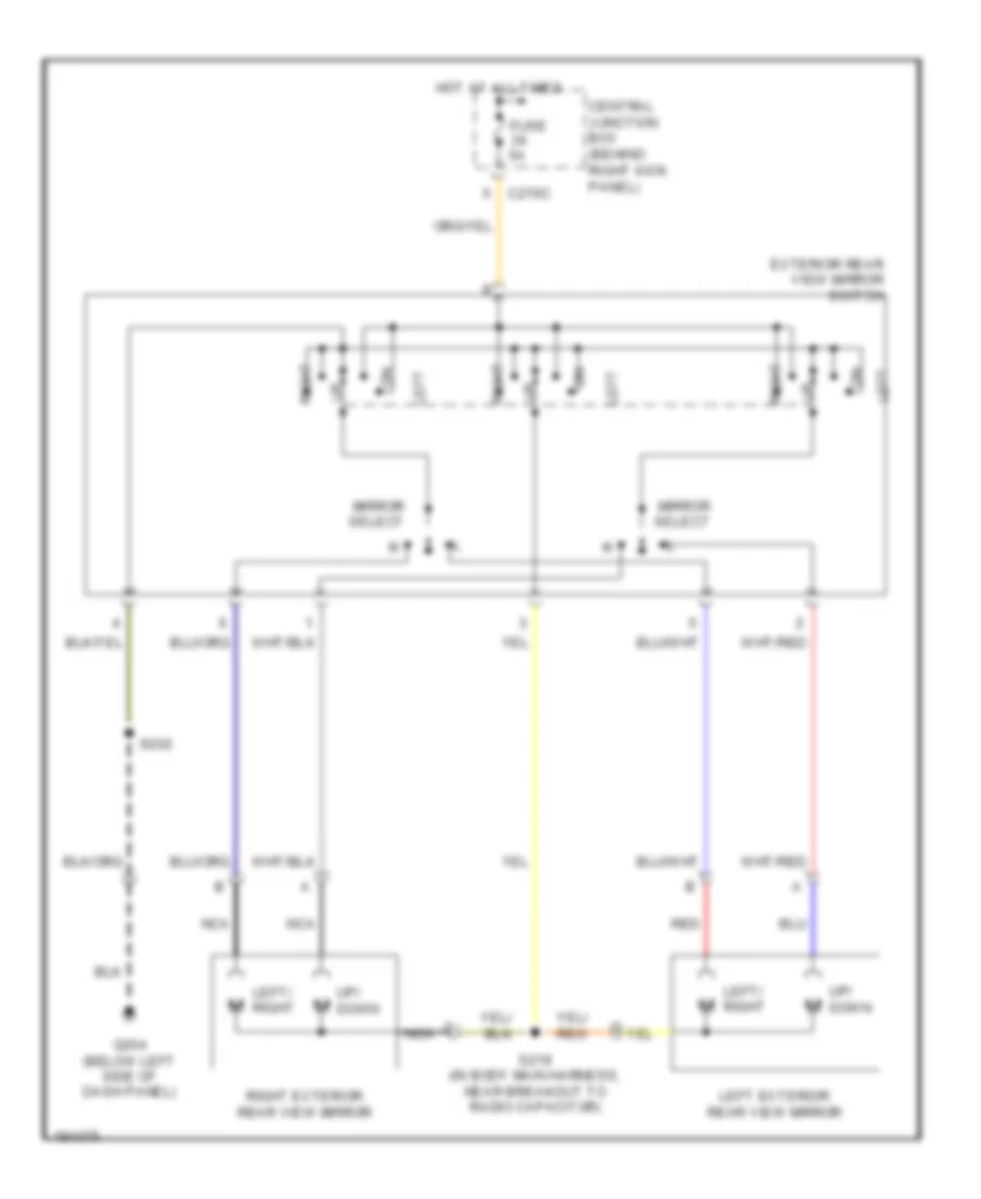
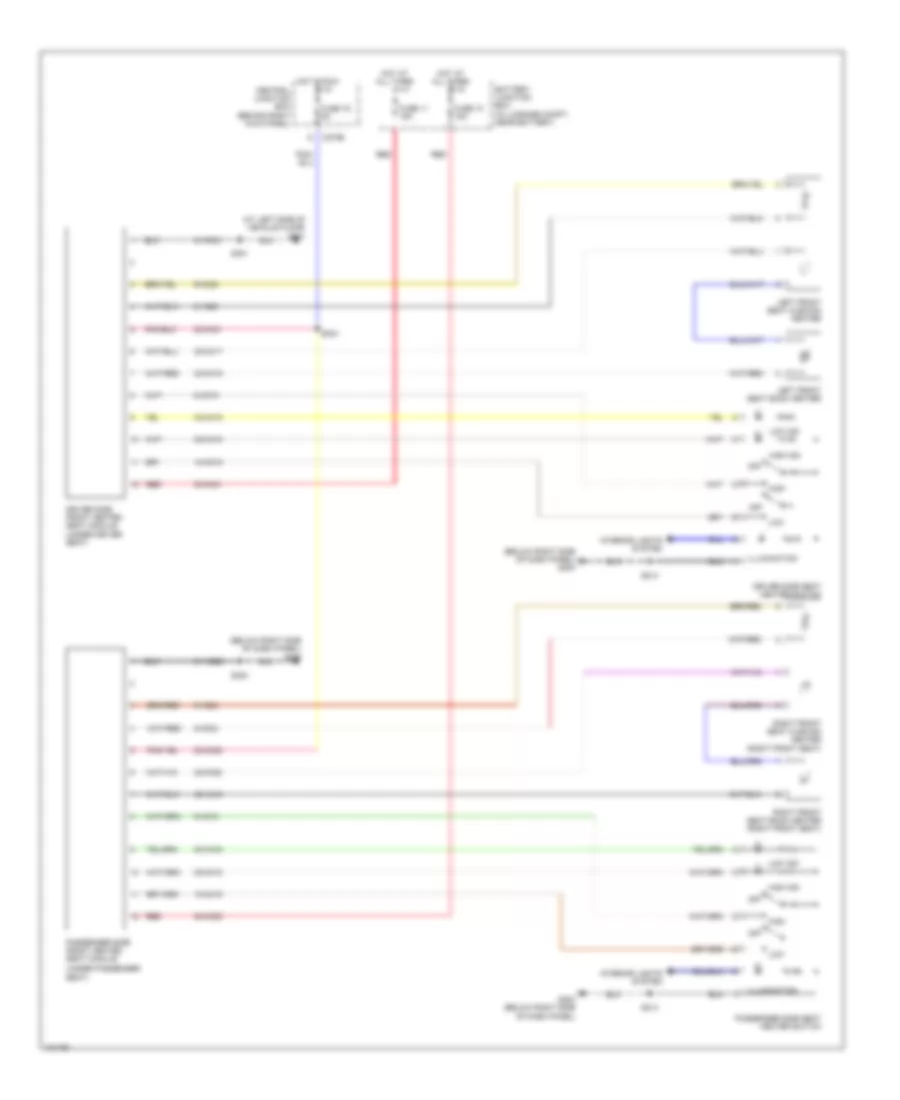
Power Mirrors Wiring Diagram for Ford Thunderbird 2005
 https://portal-diagnostov.com/license.html
Automotive Electricians Portal FZCO
Automotive Electricians Portal FZCO
https://portal-diagnostov.com/license.html
https://portal-diagnostov.com/license.html
Automotive Electricians Portal FZCO
Automotive Electricians Portal FZCOList of elements for Power Mirrors Wiring Diagram for Ford Thunderbird 2005:
- C270c
- Central junction box (behind right kick panel)
- Exterior rear view mirror switch
- Fuse 5a
- G204 (below left side of dash panel)
- Hot at all times
- Left
- Left exterior rear view mirror
- Left/ right
- Mirror select
- Nca
- Red
- Right
- Right exterior rear view mirror
- S202
- S219 (in body main harness, near breakout to radio capacitor)
- Up/ down
POWER SEATS
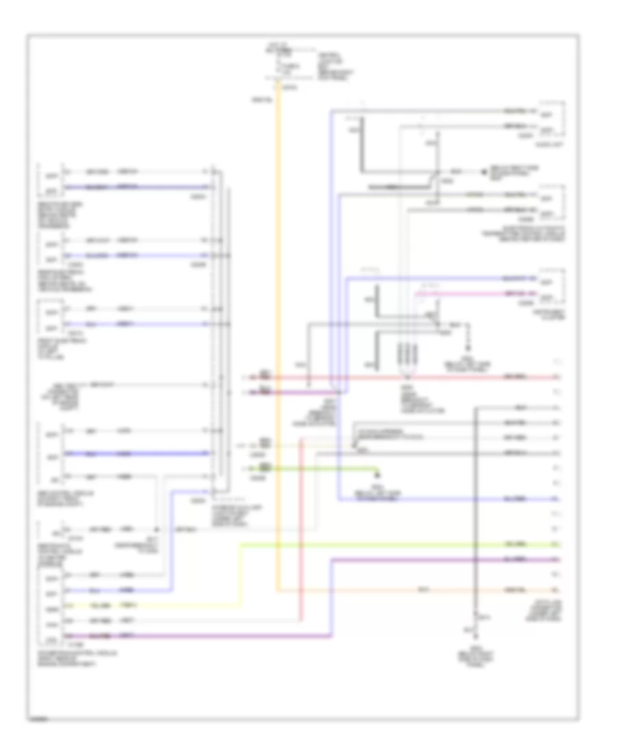
Heated Seats Wiring Diagram for Ford Thunderbird 2005
 https://portal-diagnostov.com/license.html
Automotive Electricians Portal FZCO
Automotive Electricians Portal FZCO
https://portal-diagnostov.com/license.html
https://portal-diagnostov.com/license.html
Automotive Electricians Portal FZCO
Automotive Electricians Portal FZCOList of elements for Heated Seats Wiring Diagram for Ford Thunderbird 2005:
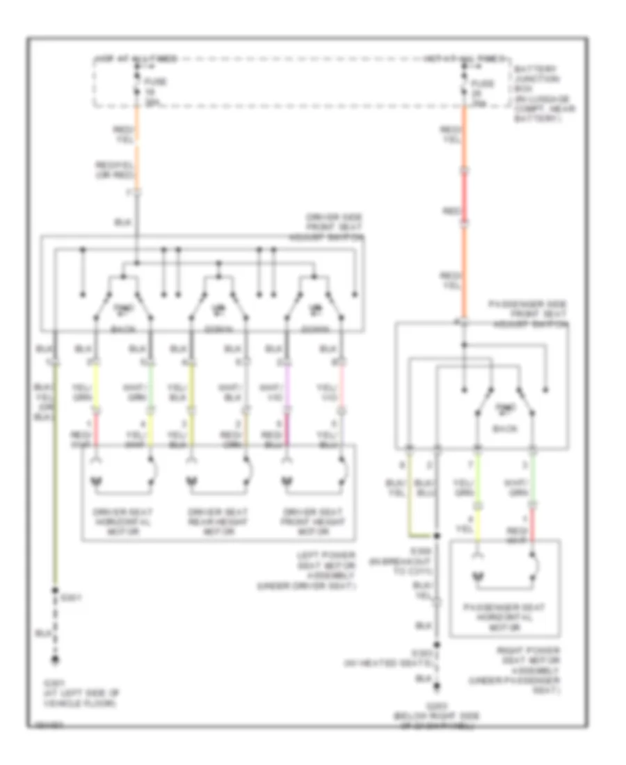
- (at left side of vehicle floor) g301
- (below right side of dash panel) g203
- (under passenger seat)
- 10-hc15
- 10-hc18
- 20-hc21
- 20-hc22
- 30-hc21
- 30-hc22
- 31-hc21
- 31-hc22
- 32-hc15
- 32-hc16
- 32-hc17
- 32-hc18
- 32-hc19
- 32-hc20
- 33-hc15
- 33-hc18
- 8-hc15
- 8-hc18
- 8-hc23
- 8-hc24
- 9-hc23
- 9-hc24
- Battery junction box (in luggage compt, near battery)
- C270b
- Central junction box (behind right kick panel)
- Driver side front heated seat module (under driver seat)
- Driver side seat heater switch
- Fuse 10 15a
- Fuse 11 15a
- Fuse 16 5a
- G203 (below right side of dash panel)
- High
- High ind
- Hot at all times
- Hot in run
- Illumination
- Interior lights system
- Left front seat back heater
- Left front seat cushion heater
- Low
- Low ind
- Off
- Passenger side front heated seat module
- Passenger side seat heater switch
- Red
- Right front seat back heater (right front seat)
- Right front seat cushion heater (right front seat)
- S214
- S301
- S303
- S304
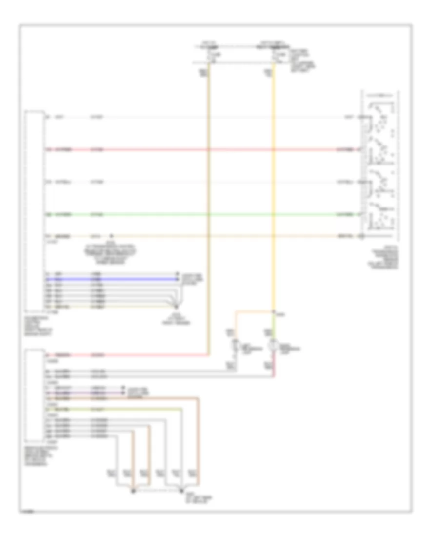
Power Seats Wiring Diagram for Ford Thunderbird 2005
 https://portal-diagnostov.com/license.html
Automotive Electricians Portal FZCO
Automotive Electricians Portal FZCO
https://portal-diagnostov.com/license.html
https://portal-diagnostov.com/license.html
Automotive Electricians Portal FZCO
Automotive Electricians Portal FZCOList of elements for Power Seats Wiring Diagram for Ford Thunderbird 2005:
- Back
- Battery junction box (in luggage compt, near battery)
- Down
- Driver seat front height motor
- Driver seat horizontal motor
- Driver seat rear height motor
- Driver side front seat adjust switch
- Fuse 30a
- Fwd
- G203 (below right side of dash panel)
- G301 (at left side of vehicle floor)
- Hot at all times
- Left power seat motor assembly (under driver seat)
- Passenger seat horizontal motor
- Passenger side front seat adjust switch
- Red
- Right power seat motor assembly (under passenger seat)
- S300 (in breakout to c311)
- S301
- S303 (w/ heated seats)
POWER TOP/SUNROOF
Power Top/Sunroof Wiring Diagram for Ford Thunderbird 2005
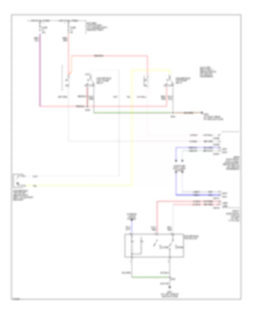 https://portal-diagnostov.com/license.html
Automotive Electricians Portal FZCO
Automotive Electricians Portal FZCO
https://portal-diagnostov.com/license.html
https://portal-diagnostov.com/license.html
Automotive Electricians Portal FZCO
Automotive Electricians Portal FZCOList of elements for Power Top/Sunroof Wiring Diagram for Ford Thunderbird 2005:
- 10-ag15
- 10-ag24
- 4-eg11
- 4-eg12a
- 5-eg11
- 5-eg12a
- 8-ag15
- 8-ag16
- 87a
- Auxiliary relay box 1 (behind seats, on vehicle crossbeam)
- Battery junction box (in luggage compt, near battery)
- C201b
- C201c
- C420b
- C420c
- C420e
- Computer data lines system
- Convertible top lower relay
- Convertible top motor (behind right seat, on support bracket)
- Convertible top raise relay
- Convertible top switch
- Front electronic module (in left ``a" pillar)
- Fuse 40a
- Fuse 5a
- G300 (at right rear of vehicle floor)
- G301 (at left side of vehicle floor)
- Hot at all times
- Interior lights system
- Lower
- Raise
- Rear electronic module (rem) (behind seats, on vehicle crossbeam)
- S230
- S404
- S405
- Scp+
- Scp-
- Vref
POWER WINDOWS
Power Windows Wiring Diagram for Ford Thunderbird 2005
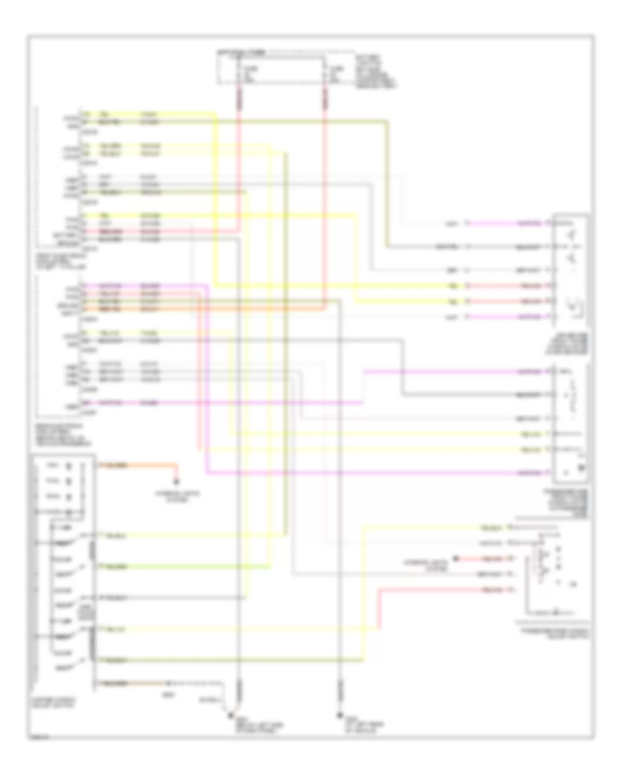 https://portal-diagnostov.com/license.html
Automotive Electricians Portal FZCO
Automotive Electricians Portal FZCO
https://portal-diagnostov.com/license.html
https://portal-diagnostov.com/license.html
Automotive Electricians Portal FZCO
Automotive Electricians Portal FZCOList of elements for Power Windows Wiring Diagram for Ford Thunderbird 2005:
- 10-aj18
- 10-aj81
- 10-aj82
- 30-aj71
- 30-aj80
- 31-aj71
- 31-aj80
- 31-aj81
- 31-aj82
- 32-aj26
- 32-aj27
- 33-aj26
- 33-aj27
- 7-aj81
- 7-aj82
- 7s-aj16
- 7s-aj40
- 7s-aj41
- 8-aj18
- 8-aj81
- 8-aj82
- Battery
- Battery junction box (bjb) (in luggage compartment, near battery)
- C201b
- C201d
- C201e
- C201g
- C420a
- C420c
- C420e
- C420f
- Down
- Driver
- Driver side front power window motor (in driver door)
- Front electronic module (fem) (in left ``a" pillar)
- Fuse 30a
- G204 (below left side of dash panel)
- G402 (at left rear of vehicle)
- Gnd
- Ground
- Hot at all times
- Interior lights system
- Master window adjust switch
- One- touch down
- Passenger
- Passenger side front power window motor (in passenger door)
- Passenger side window adjust switch
- Pwr
- Rear electronic module (rem) (behind seats, on vehicle crossbeam)
- Rest
- S500
- Vbatt
- Vpwr
- Vref
RADIO
Radio Wiring Diagram (1 of 2) for Ford Thunderbird 2005
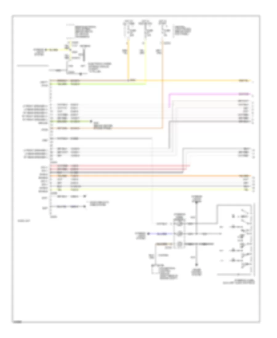 https://portal-diagnostov.com/license.html
Automotive Electricians Portal FZCO
Automotive Electricians Portal FZCO
https://portal-diagnostov.com/license.html
https://portal-diagnostov.com/license.html
Automotive Electricians Portal FZCO
Automotive Electricians Portal FZCOList of elements for Radio Wiring Diagram (1 of 2) for Ford Thunderbird 2005:
- 1-md12
- 1-md19
- 10-md10
- 10-md11
- 10-md17
- 10-md18
- 2-md12
- 2-md19
- 29-md15
- 31-md12a
- 31-md4
- 31s-pg24
- 4-eg10
- 5-eg10
- 50-md15
- 7-md12
- 7-md19
- 75-md15
- 8-md10
- 8-md11
- 8-md17
- 8-md18
- 8-md26
- 91-md15
- Ant
- Antenna
- Audio unit
- C175b
- C218a
- C240a
- C240b
- C240c
- C270a
- C420c
- Central junction box (behind right kick panel)
- Coax
- Computer data lines system
- Cruise control system
- Electronic hidden antenna module (in right ``a" pillar)
- Enable
- Fuse 10a
- Fuse 20a
- Fuse 5a
- G200 (behind center of dash panel)
- Ground
- Ham
- Hot at all times
- Hot in run or acc
- Hot in start
- Interior lights system
- Lf front speaker (+)
- Lf front speaker (-)
- Lf rear speaker (+)
- Lf rear speaker (-)
- Media
- Mem dn
- Mem up
- Mute
- Nca
- Powertrain control module (right rear of engine compt)
- Rear electronic module (rem) (behind seats, on vehicle crossbeam)
- Rt front speaker (+)
- Rt front speaker (-)
- Rt rear speaker (+)
- Rt rear speaker (-)
- S208
- S220
- Scp+
- Scp-
- Shield
- Sig (+)
- Sig (-)
- Steering wheel assembly
- Steering wheel auxiliary audio controls
- Vbatt
- Vol dn
- Vol up
- Vpwr
- Vref
Radio Wiring Diagram (2 of 2) for Ford Thunderbird 2005
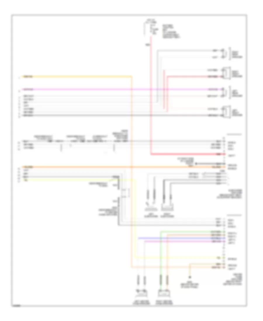 https://portal-diagnostov.com/license.html
Automotive Electricians Portal FZCO
Automotive Electricians Portal FZCO
https://portal-diagnostov.com/license.html
https://portal-diagnostov.com/license.html
Automotive Electricians Portal FZCO
Automotive Electricians Portal FZCOList of elements for Radio Wiring Diagram (2 of 2) for Ford Thunderbird 2005:
- (at right side of luggage compt) g401
- (near breakout to audio unit) s227
- (near breakout to c212) s228
- (near breakout to g200)
- (near breakout to subwoofer amplifier) s415
- Battery junction box (in luggage compartment, near battery)
- C466
- Center image amplifier (behind front center of dash)
- Enable
- Fuse 20a
- G200 (behind center of dash panel)
- Ground
- Hot at all times
- Left center image speaker
- Left front speaker
- Left rear speaker
- Left subwoofer
- Left(+)
- Left(-)
- Nca
- Red
- Right center image speaker
- Right front speaker
- Right rear speaker
- Right subwoofer
- Right(+)
- Right(-)
- S203 (near breakout to center image amplifier)
- S209
- Shield
- Sig(+)
- Sig(-)
- Subwoofer amplifier (behind right seat, on support bracket)
- Vbatt
SHIFT INTERLOCK
Shift Interlock Wiring Diagram for Ford Thunderbird 2005
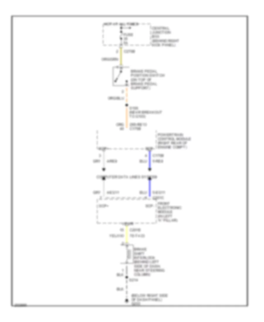 https://portal-diagnostov.com/license.html
Automotive Electricians Portal FZCO
Automotive Electricians Portal FZCO
https://portal-diagnostov.com/license.html
https://portal-diagnostov.com/license.html
Automotive Electricians Portal FZCO
Automotive Electricians Portal FZCOList of elements for Shift Interlock Wiring Diagram for Ford Thunderbird 2005:
- (below right side of dash panel) g203
- 29s-re13 c175b
- 4-eg11
- 4-re8
- 5-eg11
- 5-re8
- 7s-ta33
- Brake pedal position switch (on top of brake pedal support)
- Brake shift interlock (behind left side of dash, near steering column)
- C175b
- C201c
- C201e
- C270b
- Central junction box (behind right kick panel)
- Computer data lines system
- Front electronic module (in left "a" pillar)
- Fuse 5a
- Hot at all times
- Powertrain control module (right rear of engine compt)
- S100 (near breakout to g103)
- S214
- Scp+
- Scp-
- Vpwr
STARTING/CHARGING
Charging Wiring Diagram for Ford Thunderbird 2005
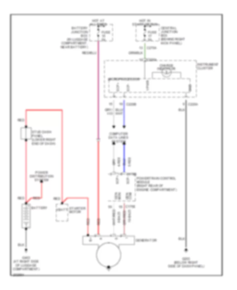 https://portal-diagnostov.com/license.html
Automotive Electricians Portal FZCO
Automotive Electricians Portal FZCO
https://portal-diagnostov.com/license.html
https://portal-diagnostov.com/license.html
Automotive Electricians Portal FZCO
Automotive Electricians Portal FZCOList of elements for Charging Wiring Diagram for Ford Thunderbird 2005:
- 10-ba25
- 4-re8
- 5-re8
- 8-ba25
- Battery
- Battery junction box (in luggage compartment, near battery)
- C175b
- C175e
- C220a
- C220b
- C270a
- Central junction box (behind right kick panel)
- Charge indicator
- Com gen
- Computer data lines system
- Fuse 5a
- G203 (below right side of dash panel)
- G403 (at right side of luggage compartment)
- Generator
- Gnd
- Hot at all times
- Hot in start or run
- Instrument cluster
- Microprocessor
- Mon gen
- Power distribution system
- Powertrain control module (right rear of engine compartment)
- Red
- Scp+
- Scp-
- Starter motor
- Stud dash panel (lower right end of dash)
- Vbatt
- Vpwr
Starting Wiring Diagram for Ford Thunderbird 2005
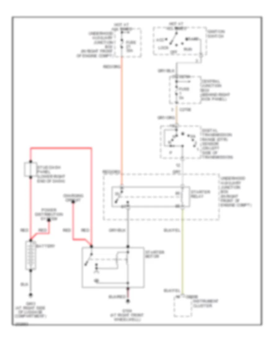 https://portal-diagnostov.com/license.html
Automotive Electricians Portal FZCO
Automotive Electricians Portal FZCO
https://portal-diagnostov.com/license.html
https://portal-diagnostov.com/license.html
Automotive Electricians Portal FZCO
Automotive Electricians Portal FZCOList of elements for Starting Wiring Diagram for Ford Thunderbird 2005:
- 3/4
- Acc
- Battery
- C220b
- C270a
- C270e
- Central junction box (behind right kick panel)
- Charging circuit
- Digital transmission range (dtr) sensor (on left
- Fuse 30a
- Fuse 5a
- G104 (at right front wheelwell)
- G403 (at right side of luggage compartment)
- Hot at all times
- Ignition switch
- Instrument cluster
- Lock
- Off
- Power distribution system
- Red
- Run
- Side of transmission)
- Start
- Starter motor
- Starter relay
- Stud dash panel (lower right end of dash)
- Underhood auxiliary junction box (in right front of engine compt)
SUPPLEMENTAL RESTRAINTS
Supplemental Restraints Wiring Diagram for Ford Thunderbird 2005
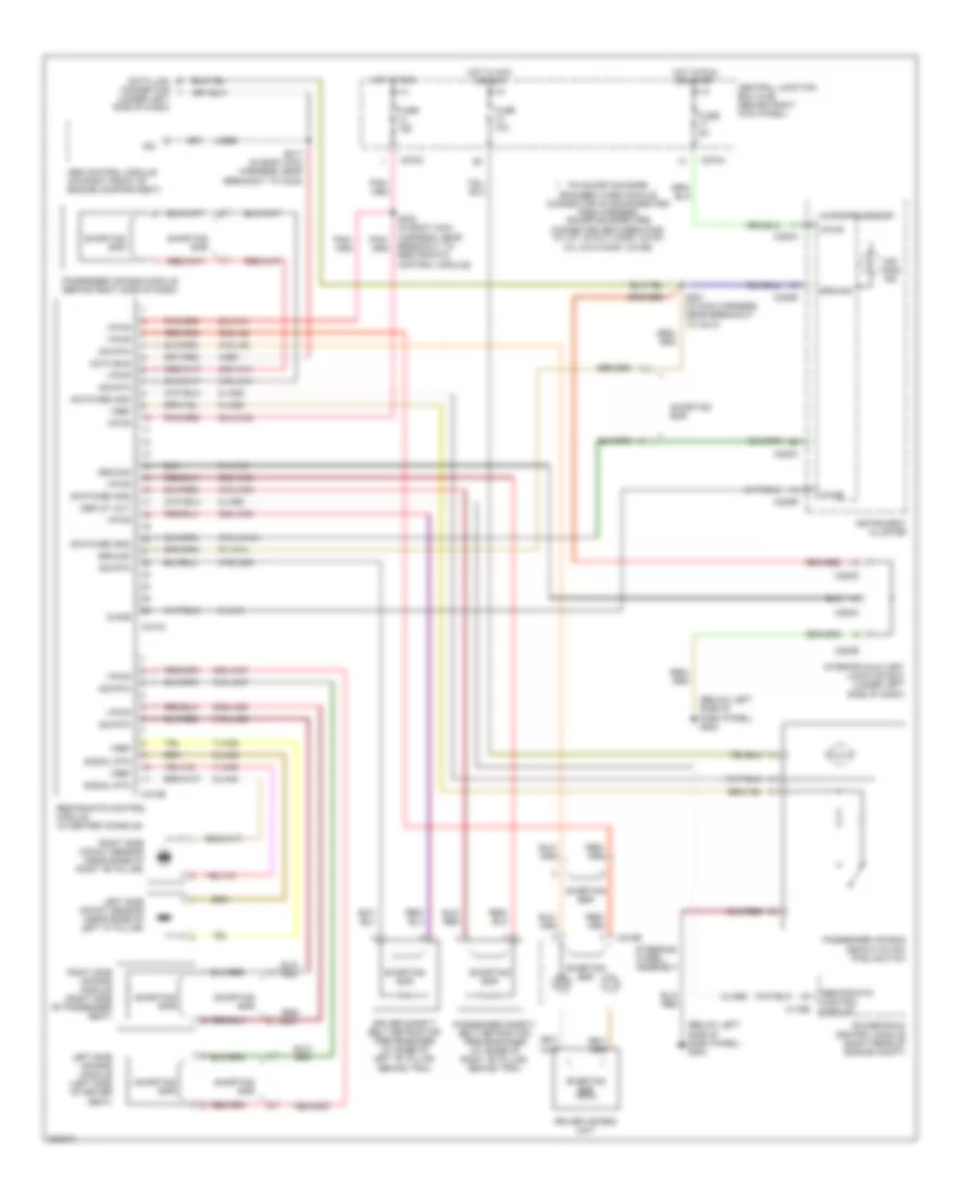 https://portal-diagnostov.com/license.html
Automotive Electricians Portal FZCO
Automotive Electricians Portal FZCO
https://portal-diagnostov.com/license.html
https://portal-diagnostov.com/license.html
Automotive Electricians Portal FZCO
Automotive Electricians Portal FZCOList of elements for Supplemental Restraints Wiring Diagram for Ford Thunderbird 2005:
- (below left side of dash panel) g204
- (under left side of dash)
- 20-ja10
- 20-ja10c
- 30s-ja11
- 30s-ja33
- 30s-ja34
- 30s-ja37
- 30s-ja38
- 30s-ja8
- 31-ja10
- 31s-ja11
- 31s-ja14a
- 31s-ja33
- 31s-ja34
- 31s-ja37
- 31s-ja38
- 31s-ja8
- 4-ee1
- 4-ee6
- 7-ja39
- 7-ja40
- 8-ja13
- 8-ja26
- 8-ja56
- 9-ja26
- 9-ja39
- 9-ja40
- 91-ja14
- Abs control module (on right front of engine compartment)
- Air bag ind
- C175b
- C218b
- C220a
- C220b
- C270a
- C270c
- C283a
- C283b
- C283d
- C310a
- C310b
- Central junction box (cjb) (behind right kick panel)
- Chime
- Data bus
- Data link connector
- Deploy out
- Driver air bag unit
- Driver safety belt retractor pretensioner (at base of left "b" pillar, behind trim)
- Fuse 10a
- Fuse 5a
- Ground
- Hot in acc or run
- Hot in run
- Hot in run or start
- Instrument cluster
- Interior auxiliary junction box (under left side of dash)
- Iso
- Left side air bag module (left side of driver seat)
- Left side impact sensor (near base of left "a" pillar)
- Microprocessor
- Passenger air bag deactivation (pad) switch
- Passenger air bag module (behind right side of dash)
- Passenger safety belt retractor pretensioner (at base of right "b" pillar, behind trim)
- Pin shorting bars engaged when module connector is disconnected from harness (shorting bars are connected between pins: 3-4, 6-7, 20 & 21 conn. c310a 2-3, 5 & 6 conn. c310b)
- Powertrain control module (right rear of engine compt)
- Restraints control module
- Restraints control module (in center console)
- Right side air bag module (right side of passenger seat)
- Right side impact sensor (near base of right "b" pillar)
- S201 (in main harness, near breakout to c213)
- S217 (in body main harness, near breakout to c248)
- S302 (in body main harness, near breakout to restraints control module)
- Shorting bar
- Sig rtn
- Signal rtn
- Steering wheel assembly
- Switched gnd
- Vpwr
- Vref
TRANSMISSION
A/T Wiring Diagram for Ford Thunderbird 2005
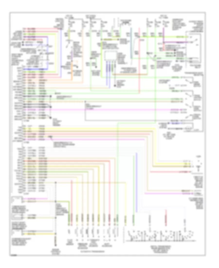 https://portal-diagnostov.com/license.html
Automotive Electricians Portal FZCO
Automotive Electricians Portal FZCO
https://portal-diagnostov.com/license.html
https://portal-diagnostov.com/license.html
Automotive Electricians Portal FZCO
Automotive Electricians Portal FZCOList of elements for A/T Wiring Diagram for Ford Thunderbird 2005:
- (at right front fender) g103
- (in right front of engine compt) underhood auxiliary junction box
- (near breakout to defrost mode actuator)
- (near breakout to g103)
- (near breakout to g204) s218
- (near breakout to ignition transformer capacitor 2)
- (near breakout to right side of engine compt)
- (right rear of engine compt) powertrain control module
- (under
- 15s-re21
- 15s-re8
- 29-re8
- 29s-re13
- 3/4
- 31-re21
- 31-re25
- 31-re26
- 31-re8
- 4-ec7
- 4-re8
- 5-ec7
- 5-re8
- 7-re14
- 7-rj28
- 8-rj22
- 8-rj28
- 8-rj33
- 8-rj39
- 8-ta21
- 8-ta26
- 8-ta27
- 8-ta37
- 8-ta38
- 8-ta39
- 8-ta40
- 8-ta51
- 8-ta67
- 8-ta68
- 8-ta74
- 9-re1
- 9-re8
- 9-rj22
- 9-rj28
- 9-ta1
- 91-re27
- 91s-ta23
- 91s-ta24
- 91s-ta47
- 91s-ta63
- 91s-ta64
- 91s-ta65
- 91s-ta69
- 91s-ta70
- Anti-lock brakes system
- Automatic transmission
- Brake in
- Brake pedal position switch (on top of brake pedal support)
- C175b
- C175e
- C175t
- C220b
- C270b
- C270d
- C270e
- C283c
- C283d
- Can+
- Can-
- Central junction box (behind right kick panel)
- Cht sens
- Computer data lines system
- Cylinder head temperature sensor (on left side of engine
- Digital transmission range sensor (dtr) (on left side of transmission)
- Dlc
- Engine controls system
- Exterior lights system
- Fluid temp sensor
- Fuse 15a
- Fuse 30a
- Fuse 5a
- G102 (right side of engine compt)
- G103 (at right front fender)
- G301 (at left side of vehicle floor)
- Ground
- Hot at all times
- Hot in run or start
- Illum
- Instrument cluster
- Interior auxiliary junction box (under left side of dash)
- Interior lights system
- Intermediate shaft speed sensor (on left side of transmission)
- Iss
- Junction box)
- Left side of dash) data link connector
- Maf sens
- Man +
- Man -
- Manual mode switch+
- Manual mode switch-
- Mass air flow sensor (on air intake assembly)
- Motor)
- Oss
- Output shaft speed sensor (on left side of transmission)
- Park sense switch
- Pcm power diode
- Pcm power relay
- Pcs a
- Pcs b
- Pcs c
- Power
- Pressure control solenoids
- Return
- S100 (near breakout to g103)
- S101
- S102
- S107
- S109
- S113
- S122 (near breakout to turbine shaft speed sensor)
- S126
- S206
- S207
- S221 (near breakout to c264)
- Scp+
- Scp-
- Shift solenoids
- Sig rtn
- Ss a
- Ss b
- Ss c
- Ss d
- Tcc sol
- Tcs
- Tft
- Throttle position sensor (on left front of engine)
- Torque conv clutch solenoid
- Tps
- Tr1
- Tr2
- Tr3a
- Tr4
- Trans control switch
- Transmission shift selector
- Tss
- Turbine shaft speed sensor (on left front of transmission)
- Underhood auxiliary junction box (in right front of engine compt)
- Vbatt
- Vref
TRUNK, TAILGATE, FUEL DOOR
Trunk, Tailgate, Fuel Door Wiring Diagram for Ford Thunderbird 2005
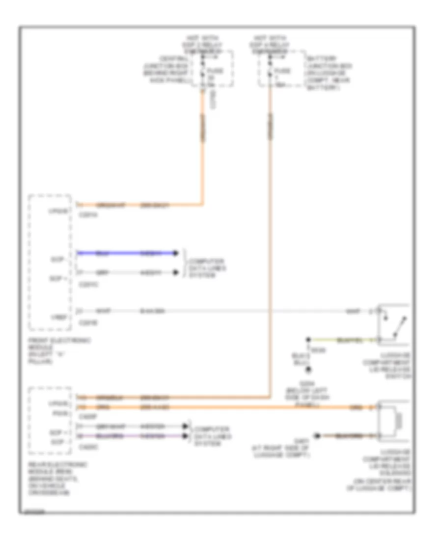 https://portal-diagnostov.com/license.html
Automotive Electricians Portal FZCO
Automotive Electricians Portal FZCO
https://portal-diagnostov.com/license.html
https://portal-diagnostov.com/license.html
Automotive Electricians Portal FZCO
Automotive Electricians Portal FZCOList of elements for Trunk, Tailgate, Fuel Door Wiring Diagram for Ford Thunderbird 2005:
- (on center rear of luggage compt)
- 29s-aa83
- 29s-dk21
- 29s-dk31
- 4-eg11
- 4-eg12a
- 5-eg11
- 5-eg12a
- 8-aa30a
- Battery junction box (in luggage compt, near battery)
- C201a
- C201c
- C201e
- C270d
- C420c
- C420f
- Central junction box (behind right kick panel)
- Computer data lines system
- Front electronic module (in left ``a" pillar)
- Fuse 15a
- Fuse 5a
- G204 (below left side of dash panel)
- G401 (at right side of luggage compt)
- Hot with ssp 2 relay energized
- Hot with ssp 4 relay energized
- Luggage compartment lid release solenoid
- Luggage compartment lid release switch
- Pwr
- Rear electronic module (rem) (behind seats, on vehicle crossbeam)
- Scp +
- Scp -
- Vpwr
- Vref
WARNING SYSTEMS
Warning Systems Wiring Diagram for Ford Thunderbird 2005
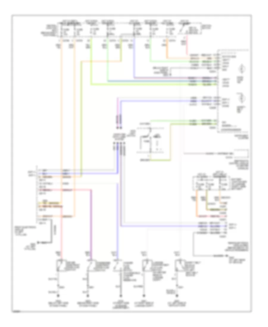 https://portal-diagnostov.com/license.html
Automotive Electricians Portal FZCO
Automotive Electricians Portal FZCO
https://portal-diagnostov.com/license.html
https://portal-diagnostov.com/license.html
Automotive Electricians Portal FZCO
Automotive Electricians Portal FZCOList of elements for Warning Systems Wiring Diagram for Ford Thunderbird 2005:
- (below right side of dash panel) g203
- 15-gg1
- 15-ja14a
- 29-al12
- 29-dk20
- 29-gg11
- 29s-dk21
- 29s-dk22
- 30-aj71
- 30-dk31
- 30s-gl46
- 30s-gl47
- 30s-gm7
- 31-al11
- 31-dk20a
- 31-dk30h
- 4-eg11
- 4-eg12a
- 4-eg8
- 5-eg11
- 5-eg12a
- 5-eg8
- 75-gg15
- 8-gc8
- 8-ge52
- 8-gl20
- 8-ja13
- 8-le21
- 9-le29
- Battery junction box (in luggage compt, near battery)
- C201a
- C201b
- C201c
- C201d
- C201e
- C220a
- C220b
- C220c
- C270a
- C270b
- C270d
- C310a
- C420a
- C420c
- C420e
- C420f
- Central junction box (behind right kick panel)
- Chime
- Computer data lines system
- Door ajar ind
- Driver side front door ajar switch
- Front electronic module (in left ``a" pillar)
- Fuse 10a
- Fuse 15a
- Fuse 30a
- Fuse 5a
- G102 (at right side of engine compartment)
- G202 (at left ``a" pillar)
- G203 (behind right side of dash panel)
- G204 (below left side of dash panel)
- G301 (at left side of vehicle floor)
- G401 (at right side of luggage compt)
- G402 (at left rear of vehicle)
- Gnd
- Hot at all times
- Hot in run or acc
- Hot in run or start
- Hot w/ spp 4 relay energized
- Hot w/ ssp 2 relay energized
- Ignition switch
- Input
- Instrument cluster
- Key in ignition switch
- Low beam
- Luggage compartment lid ajar switch (on center rear of luggage compt)
- Main light switch
- Microprocessor
- Off
- Park
- Passenger side front door ajar switch
- Rear electronic module (rem) (behind seats, on vehicle crossbeam)
- Restraints control module (in center console)
- S301
- S500
- S601
- Safety belt buckle switch (in left seat belt buckle)
- Safety belt ind
- Scp (+)
- Scp (-)
- Sig
- Sig rtn
- Switch sns
- Vbatt
- Vpwr
- Washer fluid level switch (in windshield washer fluid reservoir)
WIPER/WASHER
Wiper/Washer Wiring Diagram for Ford Thunderbird 2005
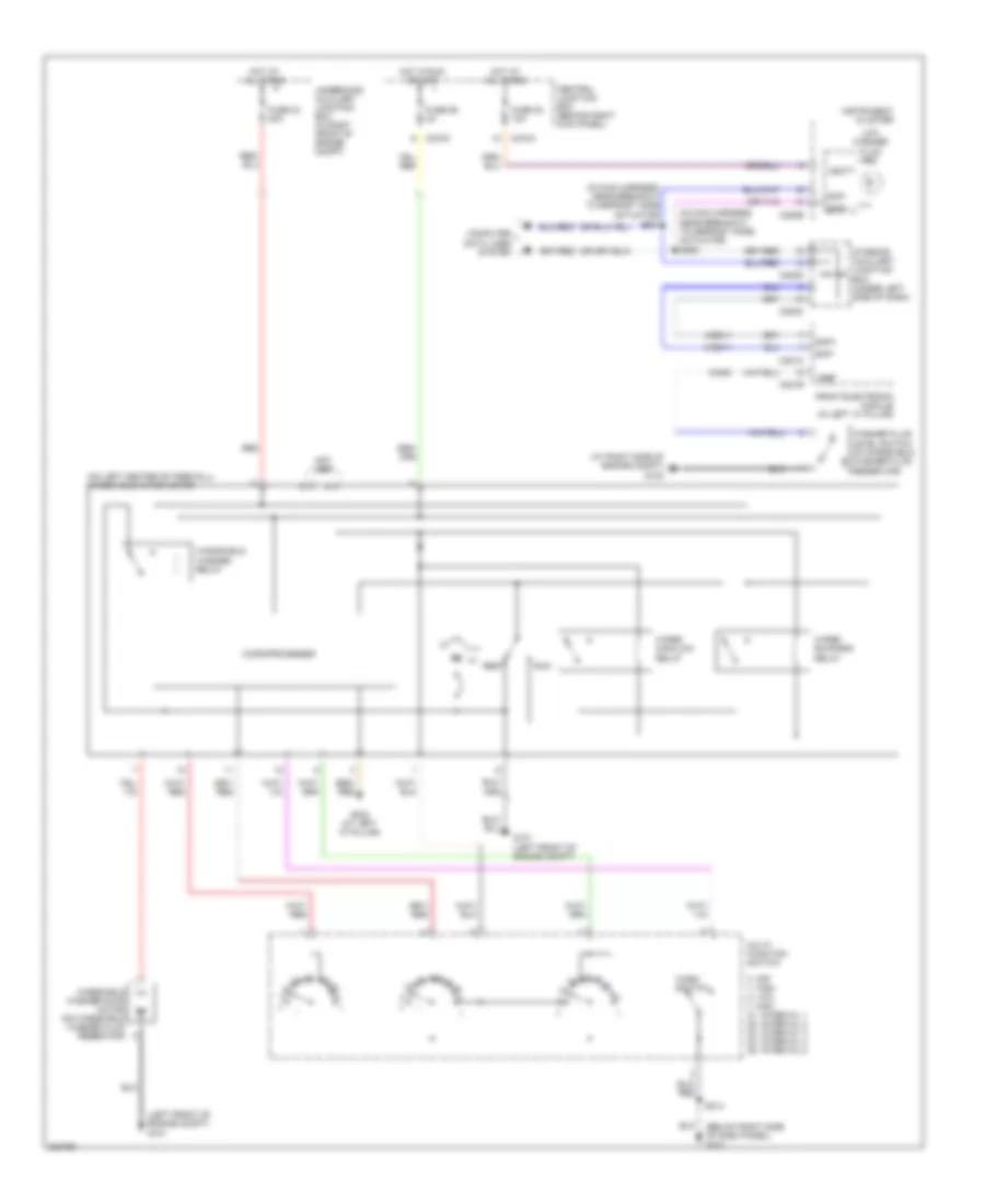 https://portal-diagnostov.com/license.html
Automotive Electricians Portal FZCO
Automotive Electricians Portal FZCO
https://portal-diagnostov.com/license.html
https://portal-diagnostov.com/license.html
Automotive Electricians Portal FZCO
Automotive Electricians Portal FZCOList of elements for Wiper/Washer Wiring Diagram for Ford Thunderbird 2005:
- (at right side of engine compt) g102
- (below right side of dash panel) g203
- (in main harness, near breakout to defrost mode actuator)
- (in main harness, near breakout to defrost mode actuator) s206
- (left front of engine compt)
- (on left center of firewall) windshield wiper motor
- 0. off 1. high 2. low 7. mist 21. interval 1 22. interval 2 23. interval 3 24. interval 4 25. interval 5
- 4-eg11
- 5-eg11
- 8-gc8
- C201b
- C201c
- C220b
- C270a
- C270c
- C283c
- C283d
- Central junction box (behind right kick panel)
- Computer data lines system
- Front electronic module (in left "a" pillar)
- Fuse 20 10a
- Fuse 24 30a
- Fuse 26 3a
- G101
- G101 (left front of engine compt)
- G202 (at left "a" pillar)
- Hot at all times
- Hot in run or acc
- Instrument cluster
- Interior auxiliary junction box (under left side of dash)
- Low washer fluid ind
- Microprocessor
- Multi- function switch
- Not used
- Red
- Rest
- Run
- S207
- S214
- Scp+
- Scp-
- Underhood auxiliary junction box (in right front of engine compt)
- Vbatt
- Vref
- Wash switch
- Washer fluid level switch (in windshield washer fluid reservoir)
- Windshield washer pump motor (on windshield washer fluid reservoir)
- Windshield washer relay
- Wiper high/low relay
- Wiper run/park relay

 Čeština
 Dansk
Dansk Deutsch
 Ελληνικά
 English
 English
 Español
 Suomi
Suomi Français
 Français
 עברית
עברית Hrvatski
 Magyar
 Italiano
 日本語
日本語 Nederlands
 Polski
 Português
 Português
 Română
 Русский
 Slovenčina
 Slovenščina
 Svenska
 Türkçe
 中文 (中国)
