AIR CONDITIONING
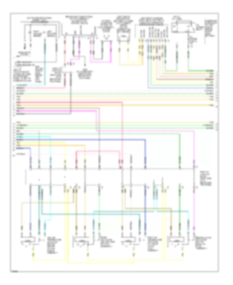
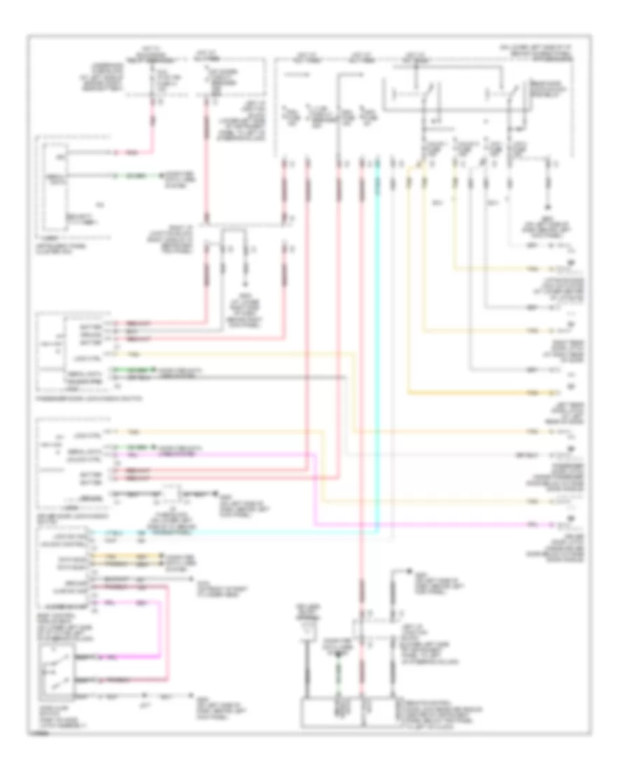
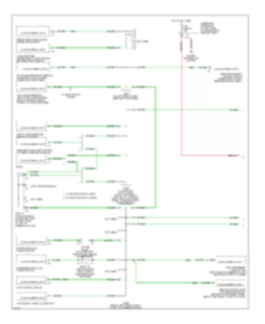
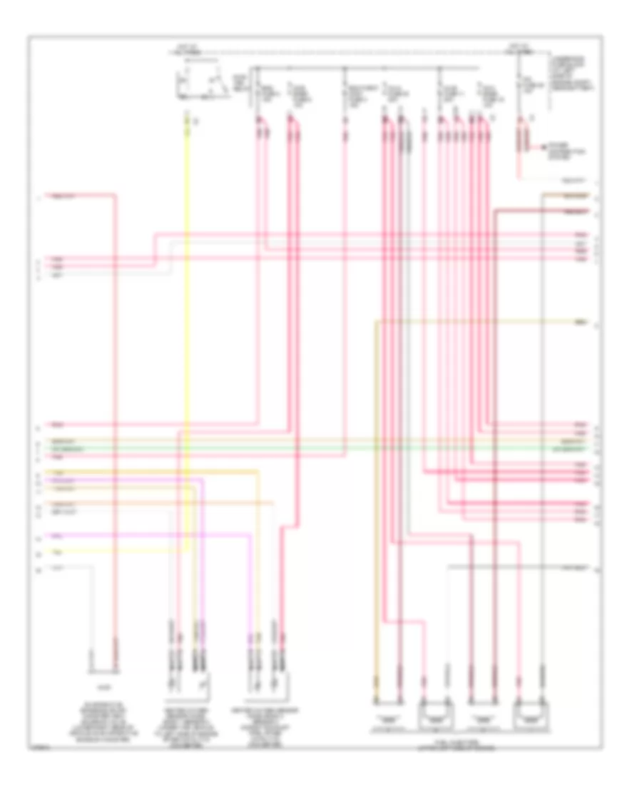
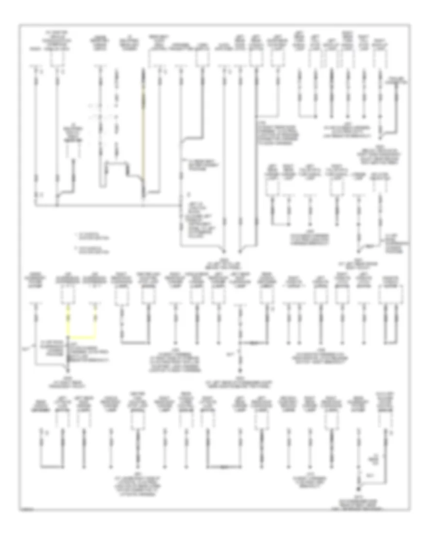
Automatic A/C Wiring Diagram (1 of 3) for Hummer H2 2008
 https://portal-diagnostov.com/license.html
Automotive Electricians Portal FZCO
Automotive Electricians Portal FZCO
https://portal-diagnostov.com/license.html
https://portal-diagnostov.com/license.html
Automotive Electricians Portal FZCO
Automotive Electricians Portal FZCO
List of elements for Automatic A/C Wiring Diagram (1 of 3) for Hummer H2 2008:
- 5-volt reference
- A/c low pressure switch (on right side of a/c a
- A/c on ind
- A/c on switch
- Accumulator at rear of engine compt)
- Air request ind
- Air request switch
- Assembly ctrl
- Auto switch
- Aux hvac ign fuse 41 10a
- Auxiliary air temperature actuator (right rear of cargo area on the front of auxiliary hvac module)
- Auxiliary blower motor (upper rear of auxiliary hvac module)
- Auxiliary blower motor control module (rear of auxiliary hvac module above blower motor-auxiliary)
- Auxiliary mode actuator (left front of auxiliary hvac module assembly)
- B(+)
- Computer data lines system
- Ctrl
- Door position sig
- Fan down switch
- Fan up switch
- Front defogger ind
- Front defogger switch
- G103 (on front of right cylinder head)
- G200 (on left side of dash, behind left kick panel)
- G203 (at lower right side of dash, behind right kick panel)
- G410 (on passenger side rear of body near d-pillar behind trim panel)
- Gmlan serial data
- Gnd
- Ground
- Hot at all times
- Hot w/ run/crank relay energized
- Hvac batt fuse 33 10a
- Hvac blwr fuse 61 40a
- Hvac control module
- Hvac ign fuse 46 10a
- I/p fuse block (on lower left side of i/p, behind access panel)
- Ig voltage
- J215
- J441
- J442
- J443
- Left i/p junction block (lower left side of instrument panel to left of steering column)
- Left i/p junction block x11 (lower left side of instrument panel to left of steering column)
- Left temperature control
- Lo press sens sig
- Logic
- Logic speed down
- Low reference
- Mode
- Mode door ctrl
- Mode down switch
- Mode up switch
- Motor speed ctrl
- Off switch
- On/ off
- Pnk
- Position sens sig
- Power distribution system
- Rear defogger ind
- Rear defogger switch
- Rear hvac fuse 30a
- Rear seat audio (rsa) control
- Recir door ctrl
- Recir- culation ind
- Recir- culation switch
- Right sw sig
- Right temperature control
- Sens sig
- Serial data
- Speed ctrl
- Speed up
- Sunload sens sig
- Tan
- Temp door ctrl
- Temp down
- Temp sens sig
- Temp up
- Underhood fuse block (at left side of engine compt, near battery)
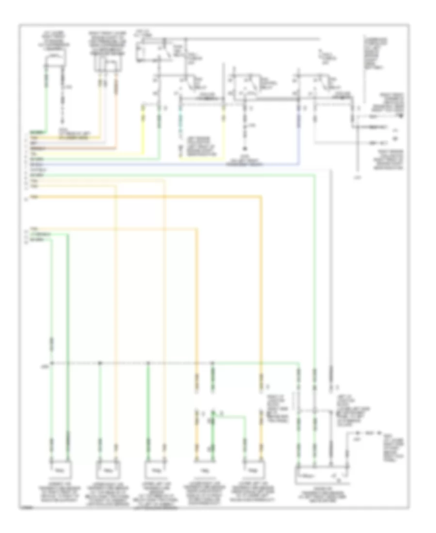
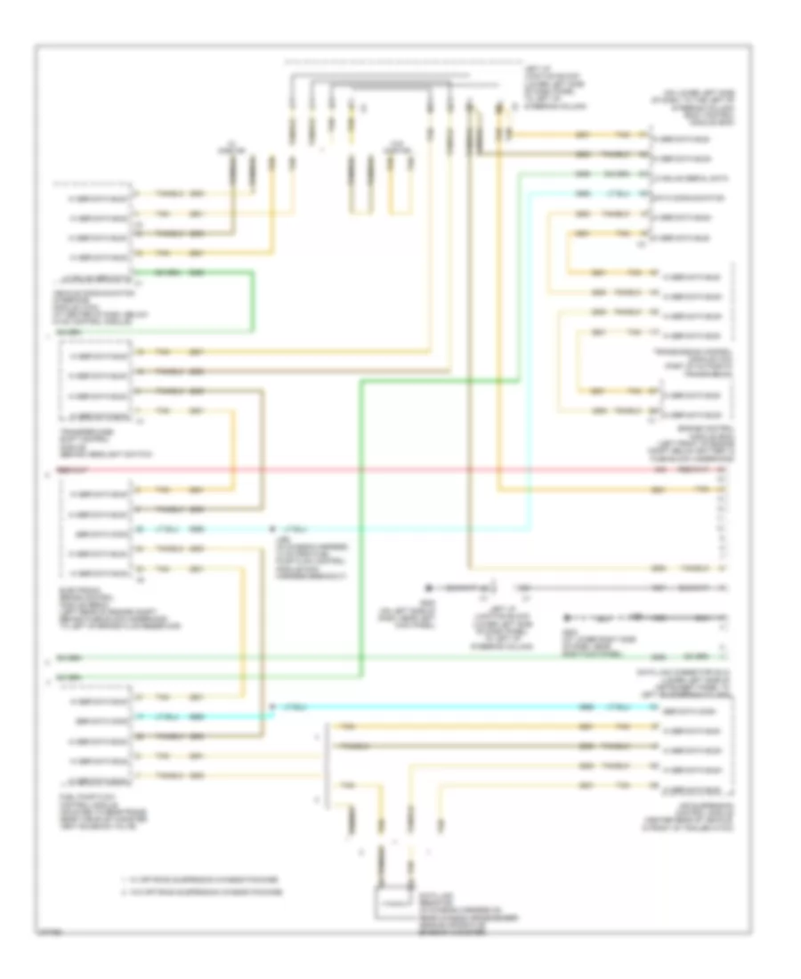
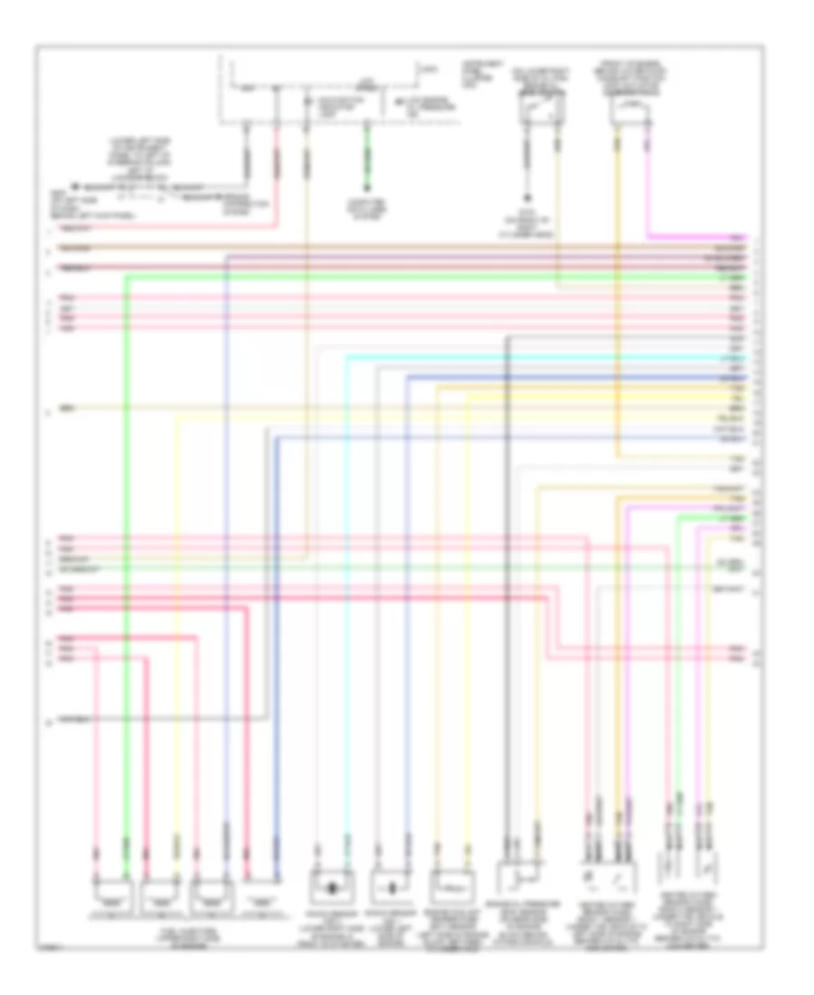
Automatic A/C Wiring Diagram (2 of 3) for Hummer H2 2008
 https://portal-diagnostov.com/license.html
Automotive Electricians Portal FZCO
Automotive Electricians Portal FZCO
https://portal-diagnostov.com/license.html
https://portal-diagnostov.com/license.html
Automotive Electricians Portal FZCO
Automotive Electricians Portal FZCOList of elements for Automatic A/C Wiring Diagram (2 of 3) for Hummer H2 2008:
- (at right lower side of dash, on hvac assembly) blower motor
- (behind right side of dash, on hvac assembly) blower motor control module
- (left front of engine compt below battery & fuse block underhood) engine control module
- (left side of engine block, between cylinder 3 & cylinder 5) engine coolant temperature (ect) sensor
- (on top center of dash) ambient light/ sunload sensor
- 4a1
- 4a4
- 4a5
- 4a6
- 4b2
- 4b3
- 4b5
- 4b6
- 5v ref
- A/c clutch
- A/c cmprsr fuse 15 10a
- A/c cmprsr relay
- Ect sig
- G200 (on left side of dash, behind left kick panel)
- G203 (at lower right side of dash, behind right kick panel)
- Gnd
- Headlights system
- Hi spd fan
- Hot at all times
- Left air temperature actuator (bottom center of hvac module assembly)
- Left i/p junction block (lower left side of instrument panel to left of steering column)
- Left sunload sensor
- Lo spd fan
- Logic
- Low ref
- Mode actuator (on left side of hvac assembly)
- Pnk
- Recirculation actuator (on top front of hvac assembly)
- Red
- Right air temperature actuator (at middle top of hvac assembly)
- Right i/p junction block (right side of i/p behind end trim panel)
- Right sunload sensor
- Rly ctrl
- Sens sig
- Spd ctrl
- Tan
- Underhood fuse block (at left side of engine compt, near battery)
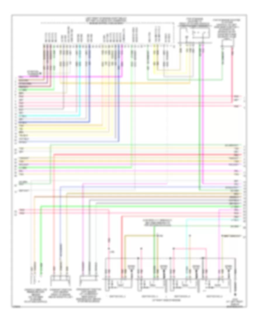
Automatic A/C Wiring Diagram (3 of 3) for Hummer H2 2008
 https://portal-diagnostov.com/license.html
Automotive Electricians Portal FZCO
Automotive Electricians Portal FZCO
https://portal-diagnostov.com/license.html
https://portal-diagnostov.com/license.html
Automotive Electricians Portal FZCO
Automotive Electricians Portal FZCOList of elements for Automatic A/C Wiring Diagram (3 of 3) for Hummer H2 2008:
- (at lower right front of engine) a/c compressor clutch
- (right front corner of vehicle on frame rail near front tow hook) g101
- (right front lower engine compt on high pressure line near compressor) a/c refrigerant pressure sensor
- 4a2
- 4a3
- 87a
- Ambient air temperature sensor (at right front of vehicle, to right of radiator support)
- Cooling fan diode 1
- Cooling fan diode 2
- Fan 1 fuse 50 40a
- Fan 2 fuse 53 40a
- Fan control relay
- Fan hi relay
- Fan lo relay
- G100 (on left front frame body mount)
- G104 (at rear of left cylinder head)
- G203 (at lower right side of dash, behind right kick panel)
- Hot at all times
- Inside air temperature sensor (in left front headliner above driver)
- J100
- J101
- J102
- J206
- J301
- Left engine cooling fan (left front of engine compt near radiator)
- Left i/p junction block (lower left side of instrument x9 panel to left of steering column)
- Lower left air temperature sensor (near middle left side of i/p under left round discharge duct)
- Lower right air temperature sensor (near middle right side of i/p in front of rectangular discharge duct)
- Pwr/ trn relay
- Right engine cooling fan (right front of engine compt near radiator)
- Right i/p junction block (right side of i/p x4 behind end trim panel)
- Tan
- Underhood fuse block (at left side of engine compt, near battery)
- Upper left air temperature sensor (at top rear of i/p below dash trim panel to left of ambient light/sunload sensor)
- Upper right air temperature sensor (at top rear of i/p below dash trim panel to right of ambient light/sunload sensor)
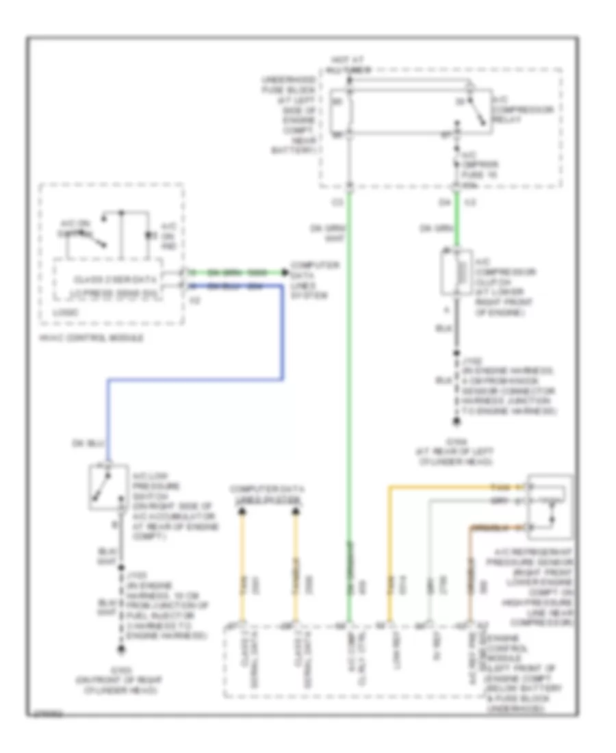
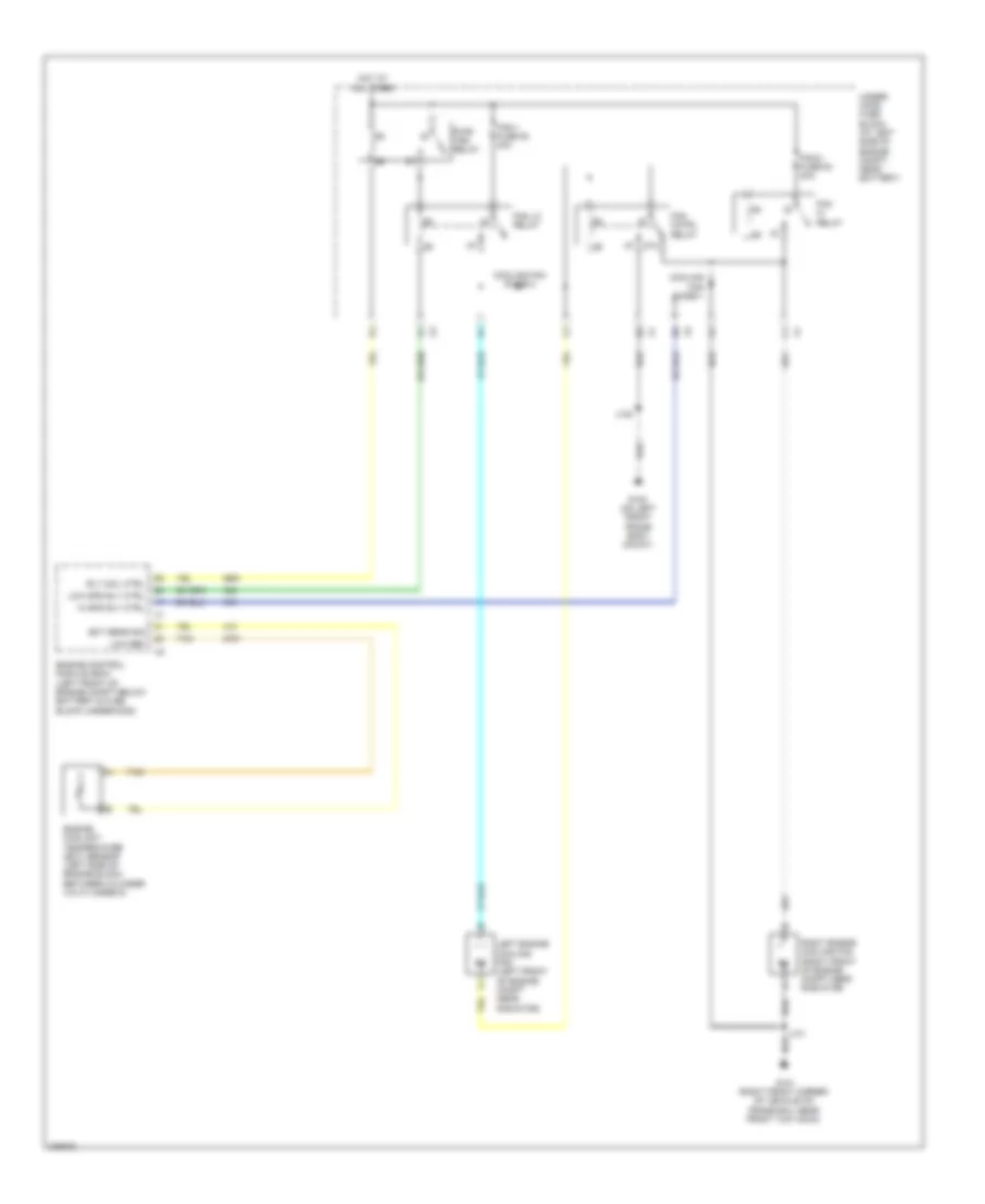
Compressor Wiring Diagram for Hummer H2 2008
 https://portal-diagnostov.com/license.html
Automotive Electricians Portal FZCO
Automotive Electricians Portal FZCO
https://portal-diagnostov.com/license.html
https://portal-diagnostov.com/license.html
Automotive Electricians Portal FZCO
Automotive Electricians Portal FZCOList of elements for Compressor Wiring Diagram for Hummer H2 2008:
- 5v ref
- A/c cmprsr fuse 15 10a
- A/c comp
- A/c compressor clutch (at lower right front of engine)
- A/c compressor relay
- A/c low pressure switch (on right side of a/c accumulator at rear of engine compt)
- A/c on ind
- A/c on switch
- A/c ref pre
- A/c refrigerant pressure sensor (right front lower engine compt on high pressure line near compressor)
- Cl rly ctrl
- Class 2
- Class 2 ser data
- Computer data lines system
- G103 (on front of right cylinder head)
- G104 (at rear of left cylinder head)
- Hot at all times
- Hvac control module
- J102 (in engine harness, 4 cm from knock sensor connector harness junction to engine harness)
- J103 (in engine harness, 10 cm from junction of fuel injector 3 harness to engine harness)
- Lo press sens sig
- Logic
- Low ref
- Serial data
- Tan
- Underhood fuse block (at left side of engine compt, near battery)
- X1 sens sig engine control module (left front of engine compt below battery & fuse block underhood)
ANTI-LOCK BRAKES
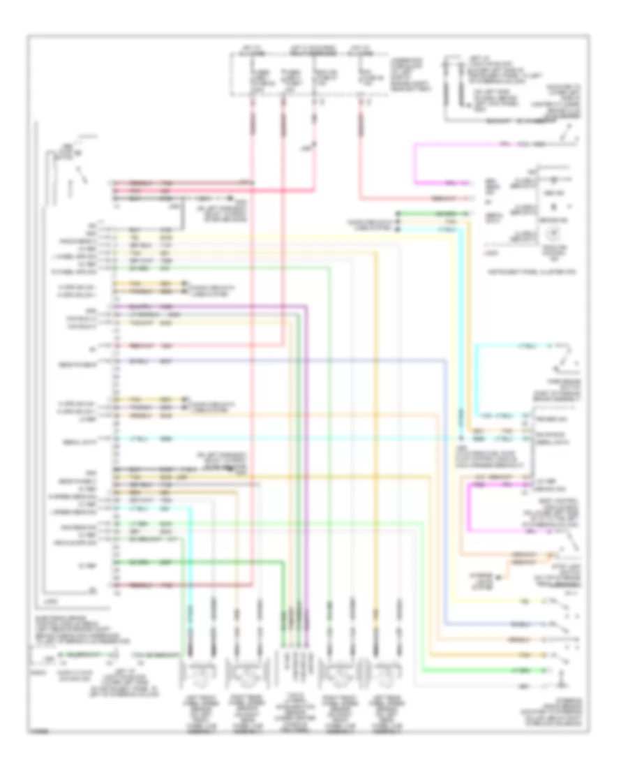
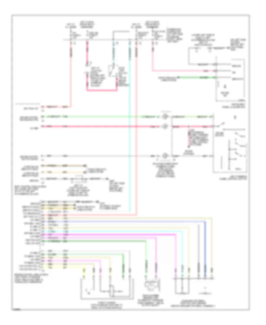
Anti-lock Brakes Wiring Diagram for Hummer H2 2008
 https://portal-diagnostov.com/license.html
Automotive Electricians Portal FZCO
Automotive Electricians Portal FZCO
https://portal-diagnostov.com/license.html
https://portal-diagnostov.com/license.html
Automotive Electricians Portal FZCO
Automotive Electricians Portal FZCOList of elements for Anti-lock Brakes Wiring Diagram for Hummer H2 2008:
- (mounted to lower left side of master cylinder)
- (on left side body mount, in front of driver door) g300
- (on left side of dash, behind left kick panel) g200
- (on right rear wheel hub assembly)
- 12v ref
- 5v ref
- Abs ind
- Abs pump m
- Ang sens sig
- Angle sens a
- Audio w/ dvd navigation
- Body control module (bcm) (on lower left side of i/p to the left of steering column)
- Brake fluid level switch
- Brake ind
- Brk sens sig
- Brk sw sig
- Can bus hi
- Can bus lo
- Class 2 ser data
- Computer data lines system
- Ecm ign fuse 47 15a
- Electronic brake control module (ebcm) (left rear of engine compt behind fuse block-underhood to left of brake fluid reservoir)
- G300 (on left side body mount, in front of driver door)
- Gmlan bus-
- Gnd
- Hi spd gmlan +
- Hi spd gmlan -
- Hot at all times
- Hot w/ run/crnk relay energized
- Ign
- Instrument panel cluster (ipc)
- Interior lights system
- Ipc fuse 39 10a
- J110
- J355
- J356
- J360 (10 cm from fuel pump flow control module main harness breakout)
- L speed sens sig
- L wheel spd sig
- Left front wheel speed sensor (on left front wheel hub assembly)
- Left i/p junction block (lower left side of instrument panel to left of steering column)
- Left i/p junction block (lower left side of x1 instrument panel to left of steering column)
- Left rear wheel speed sensor (on left rear wheel hub assembly)
- Lo ref
- Logic
- Low ref
- Motor
- Nca
- Park brake switch (part of parking brake assembly)
- Pnk
- Prk brk sw
- R speed sens sig
- R wheel spd sig
- Radio
- Right front wheel speed sensor (on right front wheel hub assembly)
- Right rear wheel speed sensor
- Sens phase b
- Sens phase c
- Serial data
- Steering angle sensor (mounted to steering column, below shift interlock solenoid)
- Stop lamp switch (on top of brake pedal bracket)
- Tan
- Traction control ind
- Underhood fuse block (at left side of engine compt, near battery)
- Vehicle spd sig
- Vses/ abs 1 fuse 52 60a
- Vses/ abs 2 fuse 7 30a
- Vss
- Yaw & lateral acceleration sensor (under center console trim panel)
ANTI-THEFT
Forced Entry Wiring Diagram for Hummer H2 2008
 https://portal-diagnostov.com/license.html
Automotive Electricians Portal FZCO
Automotive Electricians Portal FZCO
https://portal-diagnostov.com/license.html
https://portal-diagnostov.com/license.html
Automotive Electricians Portal FZCO
Automotive Electricians Portal FZCOList of elements for Forced Entry Wiring Diagram for Hummer H2 2008:
- (on lower left side of i/p, behind access panel) i/p fuse block
- 3b2
- 3b4
- 4a7
- Ajar sw sig
- Aux hvac ign fuse 41 10a
- Batt pos
- Batter
- Body control module (bcm) (on lower left side of i/p to the left of steering column)
- Closed sw sig
- Coax
- Computer data lines system
- Data bus+
- Data bus-
- Ddm fuse 15a
- Driver door latch (inside driver door below outside door handle)
- Driver door lock/window switch
- G103 (on front of right cylinder head)
- G200 (on left side of dash, behind left kick panel)
- G203 (at lower right side of dash, behind right kick panel)
- Gmlan serial data
- Ground
- Hood ajar switch (part of hood latch assembly)
- Hot at all times
- Hot w/ run/crank relay energized
- I/p fuse block (on lower left side of i/p, behind access panel)
- Ign
- Info fuse 5a
- Instrument panel cluster (ipc)
- J217
- Keyless entry antenna
- Lck 1 fuse 15a
- Lck 2 fuse 15a
- Left i/p junction block (lower left side of instrument panel to left of steering column)
- Left i/p junction block (lower left side x1
- Left rear door latch (at left rear of door)
- Liftgate door lock actuator (at lower center of liftgate)
- Lock ctrl
- Lock sw sig
- Logic
- Lt dr circuit breaker 25a
- Nca
- Of instrument panel to left of steering column)
- Passenger door latch (inside passenger door below outside door handle)
- Passenger door lock/window switch
- Pdm fuse 15a
- Pnk
- Rear door lock/unlock pcb relay
- Remote control door lock receiver (rcdlr) (center of instrument panel below trim panel to left of clock)
- Right i/p junction block (right side of i/p behind end trim panel)
- Right rear door latch (at right rear of door)
- Rt doors circuit breaker cb2 25a
- Security ind
- Serial data
- Suv
- Tan
- Underhood fuse block (at left side of engine compt, near battery)
- Unlck 1 fuse 15a
- Unlck 2 fuse 15a
- Unlock control
- Unlock ctrl
- Volt
Pass-Key Wiring Diagram for Hummer H2 2008
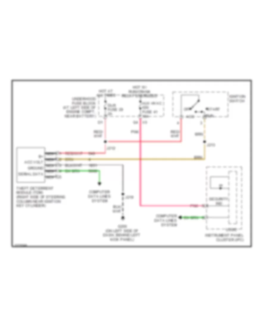 https://portal-diagnostov.com/license.html
Automotive Electricians Portal FZCO
Automotive Electricians Portal FZCO
https://portal-diagnostov.com/license.html
https://portal-diagnostov.com/license.html
Automotive Electricians Portal FZCO
Automotive Electricians Portal FZCOList of elements for Pass-Key Wiring Diagram for Hummer H2 2008:
- Acc
- Aux hvac ign fuse 41 10a
- Computer data lines system
- Dlis fuse 29 2a
- G200 (on left side of dash, behind left kick panel)
- Hot at all times
- Hot w/ run/crank relay energized
- Ignition switch
- Instrument panel cluster (ipc)
- J212
- J213
- J219
- Logic
- Nca b+ nca acc volt nca ground nca serial data nca
- Off
- Pnk
- Run
- Security ind
- Start
- Theft deterrent module (tdm) (right side of steering column near ignition key cylinder)
- Underhood fuse block (at left side of engine compt, near battery)
BODY CONTROL MODULES
Body Control Modules Wiring Diagram (1 of 2) for Hummer H2 2008
 https://portal-diagnostov.com/license.html
Automotive Electricians Portal FZCO
Automotive Electricians Portal FZCO
https://portal-diagnostov.com/license.html
https://portal-diagnostov.com/license.html
Automotive Electricians Portal FZCO
Automotive Electricians Portal FZCOList of elements for Body Control Modules Wiring Diagram (1 of 2) for Hummer H2 2008:
- 12v ref
- 5v ref
- A/t shift lock ctrl
- Acc
- Ambient light sens sig
- Anti-lock brakes system
- Anti-theft system
- Batt pos volt
- Bcm fuse 10a
- Body control module (bcm) (on lower left side of i/p to the left of steering column)
- Brake sw sig
- Computer data lines system
- Courtesy lamp ctrl
- Cruise control system
- Cruise ctrl ind dimming ctrl
- Cruise ctrl sw sig
- Dim fuse 15a
- Exterior lights system
- G200 (on left side of dash, behind left kick panel)
- Gnd
- Hazard sw left turn sig
- Hazard sw right turn sig
- Hazard sw sig
- Headlamp dimmer sw sig
- Headlamp flash to pass sig
- Headlamp sw park lamps sig
- Headlamps off sig
- Headlamps on sig
- Headlights system
- Hi spd gmlan serial data bus +
- Hi spd gmlan serial data bus -
- Hot at all times
- I/p fuse block (on lower left side of i/p, behind access panel)
- Ign iii volt
- Ign volt
- Ignition switch
- Inadvertent pwr ctrl
- Ind dimming ctrl
- Instrument lamps dimmer sw sig
- Instrument lamps dimming ctrl
- Interior lamp defeat sw sig
- Interior lights system
- Is lps fuse 20a
- J213
- Led dimming sply
- Lo spd gmlan serial data
- Low ref
- Off
- Pnk
- Run
- Security ind lamp ctrl
- Serial data communication enable
- Shift interlock system
- Sound systems
- Sound, cruise control & transmissions systems
- Start
- Steering wheel ctrl sw sig
- Tan
- Tap up/tap dn sw sig
- Tow/haul sw sig
- Traction ctrl sw sig
- Transmissions system
- Windshield washer sw sig
- Windshield wiper sw hi sig
- Windshield wiper sw lo sig
- Wiper/washer system
- X1 left i/p junction block (lower left side of x1 dash to left of steering column)
Body Control Modules Wiring Diagram (2 of 2) for Hummer H2 2008
 https://portal-diagnostov.com/license.html
Automotive Electricians Portal FZCO
Automotive Electricians Portal FZCO
https://portal-diagnostov.com/license.html
https://portal-diagnostov.com/license.html
Automotive Electricians Portal FZCO
Automotive Electricians Portal FZCOList of elements for Body Control Modules Wiring Diagram (2 of 2) for Hummer H2 2008:
- (on front of right cylinder head) g103
- 5v ref
- Accessory wakeup serial data
- Anti-theft system
- Backup lamp rly ctrl
- Batt pos volt
- Body control module (bcm) (on lower left side of i/p to the left of steering column)
- Chmsl ctrl
- Ctsy fuse 15a
- Current sens sig
- Door locks system
- Dr lock ctrl
- Drl rly ctrl
- Exterior lights system
- Exterior lights, mirrors & navigation systems
- Front windshield wiper sw hi sig
- Gnd
- Headlamp hi beam rly ctrl
- Headlamp lo beam rly ctrl
- Headlights system
- Hood ajar sw sig
- Hood closed sw sig
- Horn rly ctrl
- Horns system
- Hot at all times
- I/p fuse block (on lower left side of i/p, behind access panel)
- Ign volt
- Instrument cluster system
- Interior lights system
- Intrusion sens alarm on sig
- Intrusion sens armed sig
- Ipc fuse 41 10a
- Left trailer turn sig lamp ctrl
- Lf turn sig lamp ctrl
- Low ref
- Lr dr ajar sw sig
- Lr turn sig lamp ctrl
- Lt stop trn fuse 15a
- Master sw lockout rr sig
- Master sw lockout sig
- Master sw lr dn sig
- Master sw lr up sig
- Master sw rr dn sig
- Master sw rr up sig
- Midgate ajar ind sig
- Pnk
- Power distribution system
- Power windows system
- Prk brk sw sig
- Prk lamp rly ctrl
- Rear dr lock sw sig
- Rear wiper/washer sw ctrl
- Rf turn sig lamp ctrl
- Right trailer turn sig lamp ctrl
- Rr dr ajar sw sig
- Rr turn sig lamp ctrl
- Rt stop trn fuse 15a
- Run/crank rly ctrl
- Starting/charging system
- Stop lamp ctrl
- Stop lamps fuse 15a
- Tan
- Tcc brk sig
- Underhood fuse block (at left side of engine compt, near battery)
- Windshield wiper mtr prk sw sig
- Windshield wiper sw sig 1
- Windshield wiper sw sig 2
- Wiper/washer system
COMPUTER DATA LINES
Computer Data Lines Wiring Diagram (1 of 2) for Hummer H2 2008
 https://portal-diagnostov.com/license.html
Automotive Electricians Portal FZCO
Automotive Electricians Portal FZCO
https://portal-diagnostov.com/license.html
https://portal-diagnostov.com/license.html
Automotive Electricians Portal FZCO
Automotive Electricians Portal FZCOList of elements for Computer Data Lines Wiring Diagram (1 of 2) for Hummer H2 2008:
- (not used)
- (upfitter provisional)
- 3b1
- Audio amplifier (under front floor console, between front seats)
- Digital radio receiver (behind glove box)
- Driver door/lock window switch
- Hot at all times
- Hvac control module
- I/p fuse block (on lower left side of dash, behind access panel)
- Inflatable restraint sensing & diagnostic module (sdm) (under left front seat)
- Inflatable restraint vehicle rollover sensor (below center console in front of audio amplifier)
- Instrument panel cluster (ipc)
- Jx205 (below left side of dash, to left of steering column)
- Jx206 (w/ onstar & digital radio) (below left side of dash, near instrument panel to engine compt pass through)
- Jx207 (on left side of dash, near left kick panel)
- Left i/p junction block (lower left side of dash panel, to left of steering column)
- Lo gmlan serial data
- Ltr fuse 44 15a
- Memory seat module (msm) (under driver seat)
- Nca
- Passenger door lock/ window switch
- Power distribution system
- Radio
- Rear heated seat control module (under front of left rear second row seat)
- Rear seat audio (rsa) control (at rear of center console)
- Remote control door lock receiver (rcdlr) (center of instrument panel below trim panel to left of clock)
- Right i/p junction block (right side of dash behind end trim panel)
- Theft deterrent module (tdm) (right side of steering column near ignition key cylinder)
- Underhood fuse block (at left side of engine compt, near battery)
- W/ head curtain air bag
- W/ onstar & digital radio
- W/o onstar & digital radio
Computer Data Lines Wiring Diagram (2 of 2) for Hummer H2 2008
 https://portal-diagnostov.com/license.html
Automotive Electricians Portal FZCO
Automotive Electricians Portal FZCO
https://portal-diagnostov.com/license.html
https://portal-diagnostov.com/license.html
Automotive Electricians Portal FZCO
Automotive Electricians Portal FZCOList of elements for Computer Data Lines Wiring Diagram (2 of 2) for Hummer H2 2008:
- (on lower left side of dash, to the left of steering column) body control module (bcm)
- Air suspension control module (center rear of vehicle, in front of trailer hitch)
- Data communication
- Data link connector (dlc) (lower left side of instrument panel to left of steering column)
- Data link resistor (in chassis harness on rear chassis crossmember near evaporative emission canister)
- Electronic brake control module (ebcm) (left rear of engine compt behind fuse block-underhood to left of brake fluid reservoir)
- Engine control module (ecm) (left front of engine compt below battery & fuse block underhood)
- Fuel pump flow control module (mounted to rear frame near the evap canister vent solenoid valve)
- G200 (on left side of dash, near left kick panel)
- G203 (at lower right side of dash, near right kick panel)
- Hi ser data bus+
- Hi ser data bus-
- J225
- J360 (in chassis harness, 10 cm from fuel pump flow control module main harness breakout)
- Left i/p junction block (lower left side of dash panel to left of steering column)
- Left i/p junction block (lower left side of dash panel, to left of steering column)
- Lo gmlan ser data
- Lo gmlan serial data
- Ser data comm
- Tan
- Transfer case shift control module (behind headlight switch)
- Transmission control module (tcm) (part of automatic transmission)
- Vehicle communication interface module (vcim) (at center of dash, below hvac control module)
- W/ off road suspension chassis package
- W/ onstar
- W/o off road suspension chassis package
- W/o onstar
COOLING FAN
Cooling Fan Wiring Diagram for Hummer H2 2008
 https://portal-diagnostov.com/license.html
Automotive Electricians Portal FZCO
Automotive Electricians Portal FZCO
https://portal-diagnostov.com/license.html
https://portal-diagnostov.com/license.html
Automotive Electricians Portal FZCO
Automotive Electricians Portal FZCOList of elements for Cooling Fan Wiring Diagram for Hummer H2 2008:
- 87a
- Cooling fan diode 1
- Cooling fan diode 2
- Ect sens sig
- Engine control module (ecm) (left front of engine compt below battery & fuse block underhood)
- Engine coolant temperature (ect) sensor (left side of engine block, between cylinder 3 & cylinder 5)
- Fan cntrl relay
- Fan hi relay
- Fan lo relay
- Fan-1 fuse 50 40a
- Fan-2 fuse 53 40a
- G100 (on left front frame body mount)
- G101 (right front corner of vehicle on frame rail near front tow hook)
- Hi spd rly ctrl
- Hot at all times
- J100
- J101
- Left engine cooling fan (left front of engine compt near radiator)
- Low ref
- Low spd rly ctrl
- Pwr/ trn relay
- Right engine cooling fan (right front of engine compt near radiator)
- Rly coil ctrl
- Tan
- Under- hood fuse block (at left side of engine compt, near battery)
CRUISE CONTROL
Cruise Control Wiring Diagram for Hummer H2 2008
 https://portal-diagnostov.com/license.html
Automotive Electricians Portal FZCO
Automotive Electricians Portal FZCO
https://portal-diagnostov.com/license.html
https://portal-diagnostov.com/license.html
Automotive Electricians Portal FZCO
Automotive Electricians Portal FZCOList of elements for Cruise Control Wiring Diagram for Hummer H2 2008:
- (lower left side of dash to left of steering column) left i/p junction block
- (on left side of dash, behind left kick panel) g200
- 12v ref
- 5v ref 1
- 5v ref 2
- Accelerator pedal position (app) sensor (above accelerator pedal assembly)
- App sen 1 sig
- App sen 2 sig
- Aux hvac ign fuse 41 10a
- B11
- Bat pos volt
- Bat pos vot
- Body control module (bcm) (on lower left side of i/p to the left of steering column)
- Bracket)
- Computer data lines system
- Cruise control ind dimming ctrl
- Cruise control switch signal
- Cruise ind
- Cruise switch
- E pnk
- Ecm batt fuse 47 10a
- Engine control module (ecm) (left front of engine compt below battery & fuse block underhood)
- G103 (on front of right cylinder head)
- G200 (on left side of dash, behind left kick panel)
- Ground
- Hi spd gmlan ser data bus+
- Hi spd gmlan ser data bus-
- Hot at all times
- Hot w/ run/ crank relay energized
- Ign
- Inflatable restraint steering wheel module coil (on steering column, behind steering wheel)
- Instrument panel cluster (ipc)
- Ipc fuse 41 10a
- J103
- J235 (in steering wheel harness between right & left steering wheel control switches)
- Left i/p junction block (lower left side of dash to left of steering column)
- Left i/p junction block (lower left x1 side of dash to left of steering column)
- Left steering wheel control switch
- Logic
- Low ref
- Misc ign fuse 37 10a
- Pnk
- Ser data
- Ser data bus+
- Ser data bus-
- Sound systems
- Stop lamp switch (on top of brake pedal pnk
- Tac motor ctrl 1
- Tac motor ctrl 2
- Tan
- Tcc brake sig
- Throttle body (top of engine, mounted to front of intake manifold)
- Tp sens 1 sig
- Tp sens 2 sig
- Underhood fuse block (at left side of engine compt, near battery)
- Vehicle speed sensor (vss) (on rear of transfer case assembly above output shaft)
- Vss high sig
- Vss low sig
DEFOGGERS
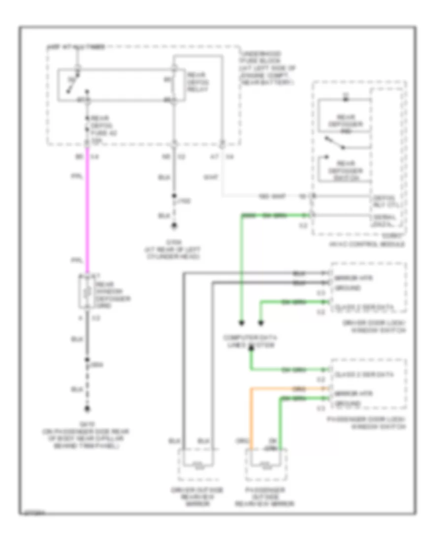
Defoggers Wiring Diagram, SUT for Hummer H2 2008
 https://portal-diagnostov.com/license.html
Automotive Electricians Portal FZCO
Automotive Electricians Portal FZCO
https://portal-diagnostov.com/license.html
https://portal-diagnostov.com/license.html
Automotive Electricians Portal FZCO
Automotive Electricians Portal FZCOList of elements for Defoggers Wiring Diagram, SUT for Hummer H2 2008:
- (in midgate harness 40 cm from midgate latch right breakout) j337
- A7 x4
- B5 x4
- Class 2 ser data
- Computer data lines system
- Contact plate
- Defog rly ctl
- Driver door lock/ window switch
- Driver outside rearview mirror
- G104 (at rear of left cylinder head)
- G403 (at left rear of passenger compt near midgate behind trim panel)
- Ground
- Hot at all times
- Hvac control module
- J102
- J339
- Logic
- Midgate window motor (inside midgate on left side)
- Mirror htr
- Passenger door lock/ window switch
- Passenger outside rearview mirror
- Rear defog fuse 42 30a
- Rear defog relay
- Rear defogger ind
- Rear defogger switch
- Rear window defogger grid
- Serial data
- Underhood fuse block (at left side of engine compt, near battery)
- X2 n5
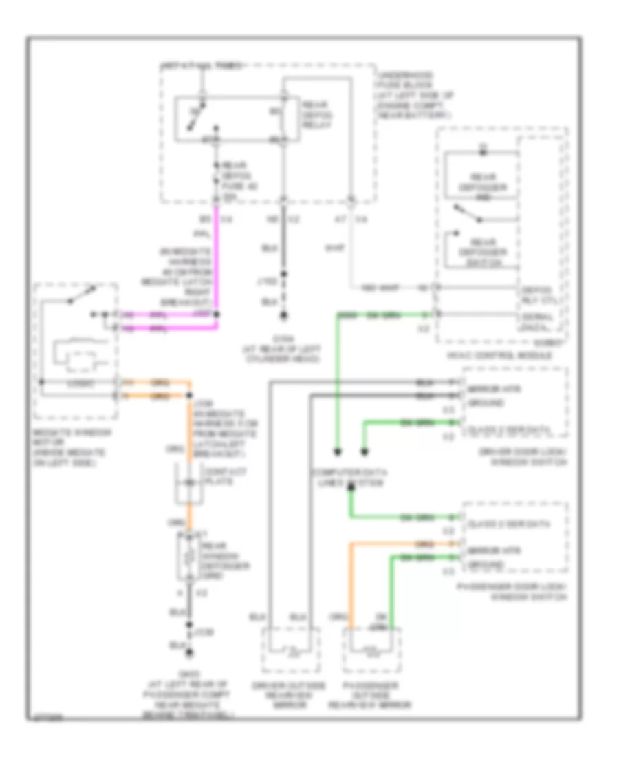
Defoggers Wiring Diagram, SUV for Hummer H2 2008
 https://portal-diagnostov.com/license.html
Automotive Electricians Portal FZCO
Automotive Electricians Portal FZCO
https://portal-diagnostov.com/license.html
https://portal-diagnostov.com/license.html
Automotive Electricians Portal FZCO
Automotive Electricians Portal FZCOList of elements for Defoggers Wiring Diagram, SUV for Hummer H2 2008:
- Class 2 ser data
- Computer data lines system
- Defog rly ctl
- Driver door lock/ window switch
- Driver outside rearview mirror
- G104 (at rear of left cylinder head)
- G410 (on passenger side rear of body near d-pillar behind trim panel)
- Ground
- Hot at all times
- Hvac control module
- J102
- J904
- Logic
- Mirror htr
- Passenger door lock/ window switch
- Passenger outside rearview mirror
- Rear defog fuse 42 30a
- Rear defog relay
- Rear defogger ind
- Rear defogger switch
- Rear window defogger grid
- Serial data
- Underhood fuse block (at left side of engine compt, near battery)
- X2 n5
- X4 a7
- X4 b5
ELECTRONIC SUSPENSION
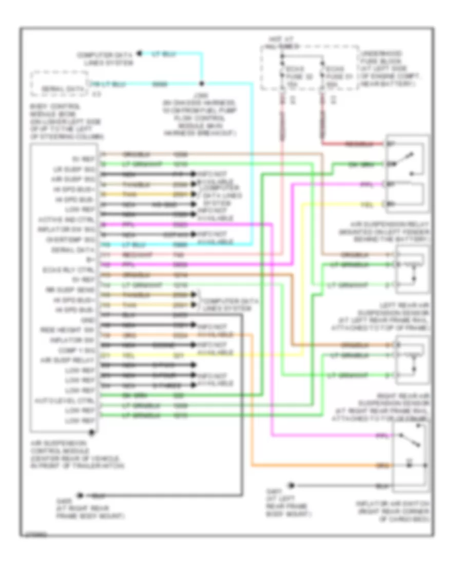
Electronic Suspension Wiring Diagram for Hummer H2 2008
 https://portal-diagnostov.com/license.html
Automotive Electricians Portal FZCO
Automotive Electricians Portal FZCO
https://portal-diagnostov.com/license.html
https://portal-diagnostov.com/license.html
Automotive Electricians Portal FZCO
Automotive Electricians Portal FZCOList of elements for Electronic Suspension Wiring Diagram for Hummer H2 2008:
- 5v ref
- Active ind ctrl
- Air susp relay
- Air susp sig
- Air suspension control module (center rear of vehicle, in front of trailer hitch)
- Air suspension relay (mounted on left fender behind the battery)
- Auto level ctrl
- Body control module (bcm) (on lower left side of i/p to the left of steering column)
- Comp 1 sig
- Computer data lines system
- Coone
- Cotwo
- Ecas fuse 32 15a
- Ecas fuse 51 60a
- Ecas rly ctrl
- G401 (at left rear frame body mount)
- G405 (at right rear frame body mount)
- Gnd
- Hi spd bus+
- Hi spd bus-
- Hot at all times
- Hs-gnd
- Inflator air switch (right rear corner of cargo bed)
- Inflator sw
- Inflator sw sig
- Info not available
- J360 (in chassis harness, 10 cm from fuel pump flow control module main harness breakout)
- Left rear air suspension sensor (at left rear frame rail, attached to top of frame)
- Low ref
- Lr susp sig
- Nca
- Overtemp sig
- P-t
- Ride height sw
- Right rear air suspension sensor (at right rear frame rail, attached to top of frame)
- Rr susp sens
- S-four
- S-three
- S-two
- Serial data
- Tan
- Underhood fuse block (at left side of engine compt, near battery)
ENGINE PERFORMANCE
6.2L VIN 8
6.2L VIN 8, Engine Performance Wiring Diagram (1 of 5) for Hummer H2 2008
 https://portal-diagnostov.com/license.html
Automotive Electricians Portal FZCO
Automotive Electricians Portal FZCO
https://portal-diagnostov.com/license.html
https://portal-diagnostov.com/license.html
Automotive Electricians Portal FZCO
Automotive Electricians Portal FZCOList of elements for 6.2L VIN 8, Engine Performance Wiring Diagram (1 of 5) for Hummer H2 2008:
- (in chassis harness 39 cm from g401 breakout) j403
- (on front of right cylinder head) g103
- 5-vol
- 5-volt ref 2
- A/c comp
- A/c pres sig
- Acc
- Acc ser data
- Accelerator pedal position (app) sensor (above accelerator pedal assembly)
- Air conditioning system
- App sens 1
- App sens 2
- Batt positive
- Body control module (bcm) (on lower left side of i/p to the left of steering column)
- Computer data lines system
- Cooling fans system
- Data bus+
- Data bus-
- Ecm batt fuse 10 10a
- Ecm ign fuse 47 15a
- Engine control module (ecm) (left front of engine compt below battery & fuse block underhood)
- Evap vent
- Exterior lights system
- Fan rel ctrl
- Ftp sig
- Fuel lvl-pri
- Fuel pump & sender assembly (in fuel tank)
- Fuel tank pressure (ftp) sensor (on fuel tank, integral to fuel pump & sender assembly)
- G103 (on front of right cylinder head)
- Ground
- Ho2s hi b1s2
- Ho2s hi b2s2
- Ho2s ht b1s2
- Ho2s ht b2s2
- Ho2s lo b1s2
- Ho2s lo b2s2
- Hot at all times
- Hot w/ run/crnk relay energized
- Iat sens sig
- Ignition switch
- Ignition vol
- J103
- J130
- J213
- J356
- Lo ref
- Lock
- Maf sens sig
- Mass air flow (maf)/intake air temperature (iat) sensor (in air induction tube)
- Mil control
- P/n sig
- Pnk
- Pnk a
- Rel ctrl
- Relay ctrl
- Rly coil ctrl
- Run
- Start
- Starting/charging system
- Tan
- Tcc brk sig
- Tcm batt fuse 12 15a
- Transmissions system
- Underhood fuse block (at left side of engine compt, near battery)
- Vehicle speed (vss) sensor (on rear of transfer case assembly above output shaft)
- Vss hi sig
- Vss lo sig
6.2L VIN 8, Engine Performance Wiring Diagram (2 of 5) for Hummer H2 2008
 https://portal-diagnostov.com/license.html
Automotive Electricians Portal FZCO
Automotive Electricians Portal FZCO
https://portal-diagnostov.com/license.html
https://portal-diagnostov.com/license.html
Automotive Electricians Portal FZCO
Automotive Electricians Portal FZCOList of elements for 6.2L VIN 8, Engine Performance Wiring Diagram (2 of 5) for Hummer H2 2008:
- Ecm/throt cont fuse 3 15a
- Eng fuse 2 15a
- Evaporative emissions (evap) canister vent solenoid valve (lower right rear of vehicle on evaporative emission canister)
- Fuel injectors (upper left side of engine)
- Heated oxygen sensor (ho2s) bank 1 sensor 2 (under the vehicle to left side of engine after catalytic converter)
- Heated oxygen sensor (ho2s) bank 2 sensor 2 (in right exhaust pipe, after catalytic converter)
- Hot at all times
- Inj-a fuse 20 20a
- Inj-b fuse 11 20a
- Ipc fuse 39 10a
- Nca
- O2-a snsr fuse 16 10a
- O2-b snsr fuse 6 10a
- Pnk
- Power distribution system
- Pwr/ trn relay
- Tan
- Underhood fuse block (at left side of engine compt, near battery)
6.2L VIN 8, Engine Performance Wiring Diagram (3 of 5) for Hummer H2 2008
 https://portal-diagnostov.com/license.html
Automotive Electricians Portal FZCO
Automotive Electricians Portal FZCO
https://portal-diagnostov.com/license.html
https://portal-diagnostov.com/license.html
Automotive Electricians Portal FZCO
Automotive Electricians Portal FZCOList of elements for 6.2L VIN 8, Engine Performance Wiring Diagram (3 of 5) for Hummer H2 2008:
- (front of engine, behind water pump) camshaft position (cmp) actuator solenoid valve
- (lower left side of instrument panel to left of steering column) left i/p junction block
- (on lower right side of oil pan) engine oil level switch
- Computer data lines system
- Engine coolant temperature (ect) sensor (left side of engine block, between cylinder 3 & 5)
- Engine oil pressure (eop) sensor (on rear side of engine block behind intake manifold)
- Fuel injectors (upper right side of engine)
- G103 (on front of right cylinder head)
- G200 (on left side of dash, behind left kick panel)
- Gnd
- Ground distribution system
- Heated oxygen sensor (ho2s) bank 1 sensor 1 (under the vehicle to left side of engine before catalytic converter)
- Heated oxygen sensor (ho2s) bank 2 sensor 1 (under the vehicle to right side of engine before catalytic converter)
- Instrument panel cluster (ipc)
- Knock sensor (ks) 1 (lower left side of engine)
- Knock sensor (ks) 2 (lower right side of engine in front of starter)
- Logic
- Low engine oil pressure ind
- Low speed
- Malfunction indicator lamp
- Nca
- Pnk
- Tan
6.2L VIN 8, Engine Performance Wiring Diagram (4 of 5) for Hummer H2 2008
 https://portal-diagnostov.com/license.html
Automotive Electricians Portal FZCO
Automotive Electricians Portal FZCO
https://portal-diagnostov.com/license.html
https://portal-diagnostov.com/license.html
Automotive Electricians Portal FZCO
Automotive Electricians Portal FZCOList of elements for 6.2L VIN 8, Engine Performance Wiring Diagram (4 of 5) for Hummer H2 2008:
- (5 cm from x111 breakout, between breakouts for ignition coils 4 & 6)
- (at right side of engine)
- (left front of engine compt below battery & fuse block underhood) engine control module (ecm)
- (top of engine mounted to intake manifold, on left side near injector 1) evaporative emission (evap) canister purge solenoid valve
- (top of engine, mounted to front of intake manifold) throttle body assembly
- 5v ref2
- A pnk
- Cam sol ctl
- Camshaft position (cmp) sensor (front of engine above crank pulley)
- Crankshaft position (ckp) sensor (at lower right rear side of engine block, behind starter solenoid)
- Ect sig
- G102 (at left front side of engine block)
- Gen fdc sig
- Ho2s ht b1s1
- Ho2s ht b2s1
- Ignition coil 2
- Ignition coil 4
- Ignition coil 6
- Ignition coil 8
- Inj 1 ctl
- Inj 2 ctl
- Inj 3 ctl
- Inj 4 ctl
- Inj 5 ctl
- Inj 6 ctl
- Inj 7 ctl
- Inj 8 ctl
- J160
- J161
- J162
- Ks1 sig
- Ks2 sig
- Lo ref
- Manifold absolute pressure (map) sensor (on top rear of engine, on intake manifold)
- Nca
- Oil lvl sw sig
- Pnk
- Red
- Sol ctrl
- Spark plug
- Starting/ charging system
- Tac mot ctl 1
- Tac mot ctl 2
- Tan
6.2L VIN 8, Engine Performance Wiring Diagram (5 of 5) for Hummer H2 2008
 https://portal-diagnostov.com/license.html
Automotive Electricians Portal FZCO
Automotive Electricians Portal FZCO
https://portal-diagnostov.com/license.html
https://portal-diagnostov.com/license.html
Automotive Electricians Portal FZCO
Automotive Electricians Portal FZCOList of elements for 6.2L VIN 8, Engine Performance Wiring Diagram (5 of 5) for Hummer H2 2008:
- (at left side of engine)
- (mounted to left side of frame assembly) fuel pressure sensor
- (mounted to rear frame near the evap canister vent solenoid valve) fuel pump flow control module
- 5-volt
- 5v ref1
- Batt
- Chg ind sig
- Ckp sig
- Cmp sig
- Computer data lines system
- Data bus+
- Data bus-
- Drain wire
- Engine control module (ecm) (left front of engine compt below battery & fuse block underhood)
- Eop sig
- Fuel fuse 18 20a
- G102 (at left front side of engine block)
- G300 (on left side body mount, in front of driver door)
- Ground
- Ho2s hi b1s1
- Ho2s hi b2s1
- Ho2s lo b1s1
- Ho2s lo b2s1
- Hot at all times
- Ic 1 ctl
- Ic 2 ctl
- Ic 3 ctl
- Ic 4 ctl
- Ic 5 ctl
- Ic 6 ctl
- Ic 7 ctl
- Ic 8 ctl
- Ign vol
- Ignition coil 1
- Ignition coil 3
- Ignition coil 5
- Ignition coil 7
- J140
- J141
- J142 (in ignition coil jumper harness, 5 cm from x111 breakout, between the breakouts for ignition coils 3 & 5)
- J423
- Lo ref
- Lo reference
- Low ref
- Map sig
- Nca
- Pnk
- Pump ctrl
- Red
- Rel ctrl
- Sens sig
- Ser data
- Spark plug
- Starting/charging system
- Tan
- Tp sens1 sig
- Tp sens2 sig
- Underhood fuse block (at left side of engine compt, near battery)
EXTERIOR LIGHTS
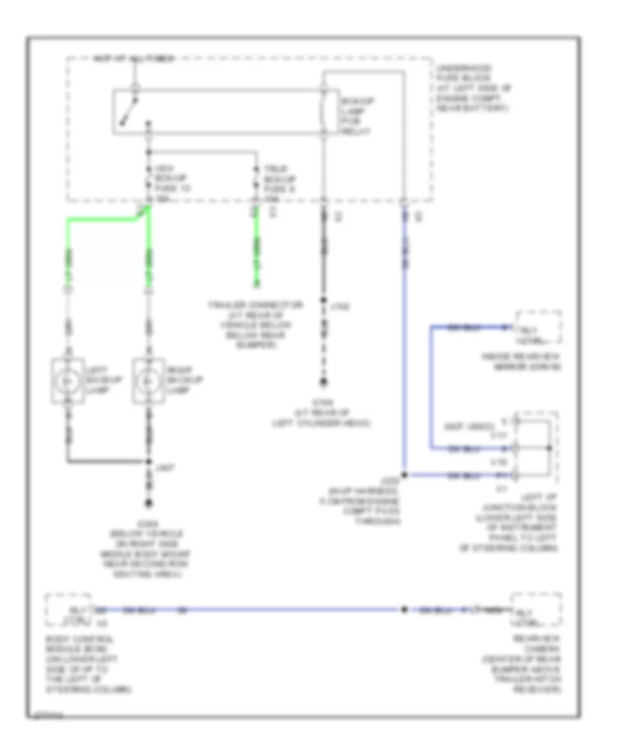
Backup Lamps Wiring Diagram for Hummer H2 2008
 https://portal-diagnostov.com/license.html
Automotive Electricians Portal FZCO
Automotive Electricians Portal FZCO
https://portal-diagnostov.com/license.html
https://portal-diagnostov.com/license.html
Automotive Electricians Portal FZCO
Automotive Electricians Portal FZCOList of elements for Backup Lamps Wiring Diagram for Hummer H2 2008:
- (not used)
- Bck/up lamp pcb relay
- Body control module (bcm) (on lower left side of i/p to the left of steering column)
- Ctrl x5
- G104 (at rear of left cylinder head)
- G304 (below vehicle on right side middle body mount near second row seating area)
- Hot at all times
- Inside rearview mirror (isrvm)
- J102
- J222 (in i/p harness, 5 cm from engine compt pass through)
- J407
- Left backup lamp
- Left i/p junction block (lower left side of instrument panel to left of steering column)
- Nca
- Rearview camera (center of rear bumper above trailer hitch receiver)
- Right backup lamp
- Rly
- Rly ctrl
- Trailer connector (at rear of vehicle below below rear bumper)
- Trlr bck/up fuse 8 10a
- Underhood fuse block (at left side of engine compt, near battery)
- Veh bck/up fuse 13 10a
- X10
- X11
Exterior Lamps Wiring Diagram (1 of 2) for Hummer H2 2008
 https://portal-diagnostov.com/license.html
Automotive Electricians Portal FZCO
Automotive Electricians Portal FZCO
https://portal-diagnostov.com/license.html
https://portal-diagnostov.com/license.html
Automotive Electricians Portal FZCO
Automotive Electricians Portal FZCOList of elements for Exterior Lamps Wiring Diagram (1 of 2) for Hummer H2 2008:
- (at left rear of passenger compt near midgate behind trim panel)
- (at left side of liftgate, near junction of right rear defogger connector to liftgate harness) j900
- (in body harness, 15.2 cm from junction of left rear marker lamp to body harness) j411
- (in forward lamp harness, 10 cm from horn-right breakout) j108
- (in forward lamp harness, 5 cm from horn-left breakout) j107
- (not used)
- (on left front frame body mount) g100
- (right front corner of vehicle on frame rail near front tow hook) g101
- (sut)
- (sut) (suv)
- (suv)
- 2b2
- Center high mounted stop lamp (chmsl)
- G203 (at lower right side of dash, behind right kick panel)
- G304 (below vehicle on right side middle body mount near second row seating area)
- G401 (at left rear frame body mount)
- G403 g410 (on passenger side rear of body near d-pillar behind trim panel)
- Hot at all times
- J100
- J101
- J303
- J395
- J405
- J407
- J901
- Left front marker lamp
- Left front roof clearance lamp
- Left front roof marker lamp
- Left i/p junction block (lower left side of instrument panel to left of steering column)
- Left park/ turn signal lamp
- Left rear marker lamp
- Left rear roof clearance lamp
- Left rear roof marker lamp
- Left tail/stop & turn signal lamp
- Left tail/stop lamp
- License lamp
- Lt prk fuse 22 15a
- Middle front roof marker lamp
- Middle rear roof marker lamp
- Nca
- Prk lamp relay
- Red
- Right front marker lamp
- Right front roof clearance lamp
- Right front roof marker lamp
- Right i/p junction block (right side of i/p behind x2 end trim panel)
- Right park/ turn signal lamp
- Right rear roof clearance lamp
- Right rear roof marker lamp
- Rt prk fuse 23 15a
- Sut
- Suv
- Trlr prk fuse 21 15a
- Underhood fuse block (at left side of engine compt, near battery)
- X12
Exterior Lamps Wiring Diagram (2 of 2) for Hummer H2 2008
 https://portal-diagnostov.com/license.html
Automotive Electricians Portal FZCO
Automotive Electricians Portal FZCO
https://portal-diagnostov.com/license.html
https://portal-diagnostov.com/license.html
Automotive Electricians Portal FZCO
Automotive Electricians Portal FZCOList of elements for Exterior Lamps Wiring Diagram (2 of 2) for Hummer H2 2008:
- (not used)
- 12v ref
- Auto
- Bck/up lamp relay
- Body control module (bcm) (on lower left side of i/p to the left of steering column)
- Brake sw sig
- Chmsl ctrl
- Computer data lines system
- Engine control module (ecm) (left front of engine compt below battery & fuse block underhood)
- G200 (on left side of dash, behind left kick panel)
- G203 (at lower right side of dash, behind right kick panel)
- G304 (below vehicle on right side middle body mount near second row seating area)
- G401 (at left rear frame body mount)
- Hazard sw
- Hazard sw sig
- Head
- Headlamp & panel dimmer switch
- Hot at all times
- Hot w/ run/crank relay energized
- Instrument panel cluster (ipc)
- Interior lights system
- Ipc fuse 39 10a
- J217
- J219
- J225
- J358 (in chassis harness, 10 cm from g300 breakout)
- J405
- J406
- J407
- Left
- Left i/p junction block (lower left side of instrument panel to left of steering column)
- Left rear turn signal lamp
- Left turn ind
- Left turn sig
- Logic
- Misc ign fuse 37 10a
- Off
- Park
- Park lp rly ctrl
- Park lps sig
- Pnk
- Red
- Right
- Right rear marker lamp
- Right rear turn signal lamp
- Right tail/ stop lamp
- Right tail/stop & turn signal lamp
- Right turn ind
- Right turn sig
- Ser data
- Stop lamp switch (on top of brake pedal bracket)
- Stop lp ctrl
- Stud 1 trlr fuse 59 40a
- Stud 2 trlr fuse 55 30a
- Tan
- Tcc brake sig
- Trailer connector (at rear of vehicle below below rear bumper)
- Transmission control module (tcm) (part of automatic transmission)
- Trlr bck/up fuse 8 10a
- Trlr stop lt fuse 1 10a
- Trlr stop lt pcb relay
- Trlr stop rt fuse 4 10a
- Trlr stop rt pcb relay
- Turn sig lp ctrl
- Turn signal/ multi-function switch
- Underhood fuse block (at left side of engine compt, near battery)
GROUND DISTRIBUTION
Ground Distribution Wiring Diagram (1 of 3) for Hummer H2 2008
 https://portal-diagnostov.com/license.html
Automotive Electricians Portal FZCO
Automotive Electricians Portal FZCO
https://portal-diagnostov.com/license.html
https://portal-diagnostov.com/license.html
Automotive Electricians Portal FZCO
Automotive Electricians Portal FZCOList of elements for Ground Distribution Wiring Diagram (1 of 3) for Hummer H2 2008:
- (if equipped) windshield washer solvent heater
- (sut) mid gate window switch
- A/c compressor clutch
- A/c low pressure switch
- Ambient light/ sunload sensor
- Automatic transmission
- Back-up lamp pcb relay
- Battery
- Body control module (bcm)
- Brake fluid level switch
- Cooling fan diode
- Data link connector (dlc)
- Driver door lock/ window switch
- Engine control module (ecm)
- Fan control relay
- Front washer diode
- Frt wash pcb relay
- G100 (on left front frame body mount)
- G101 (right front corner of vehicle on frame rail near front tow hook)
- G102 (at left front side of engine block)
- G103 (on front of right cylinder head)
- G104 (at rear of left cylinder head)
- G106 (on rear of left rear of engine compt, near left cylinder head)
- G200 (on left side of dash, behind left kick panel)
- Headlamp & panel dimmer switch
- Hood ajar switch
- Hvac control module
- I/p fuse block (on lower left side of i/p, behind access panel)
- I/p multifunction switch
- Ignition coil/ module 1
- Ignition coil/ module 2
- Ignition coil/ module 3
- Ignition coil/ module 4
- Ignition coil/ module 5
- Ignition coil/ module 6
- Ignition coil/ module 7
- Ignition coil/ module 8
- Instrument panel cluster (ipc)
- J101 (in forward lamp harness, 5 cm from ambient temperature sensor harness to forward lamp harness at right front of radiator support)
- Left daytime running lamp (drl)
- Left front park/turn signal lamp
- Left headlamp
- Left horn
- Left i/p junction block (lower left side of instrument x1
- Mass air flow (maf)/ intake air temperature (iat) sensor
- Nca
- Panel to left of steering column)
- Rear defog relay
- Rear door lock/unlock pcb relay
- Rear wash pcb relay
- Rear washer diode
- Remote control door lock receiver (rcdlr)
- Right daytime running lamp (drl)
- Right engine cooling fan
- Right front park/turn signal lamp
- Right headlamp
- Right horn
- Run/ accy relay
- Run/ crank relay
- Starter relay
- Theft deterrent module (tdm)
- Transfer case shift control module
- Turn signal/ multifunction switch
- Underhood fuse block (at left side of engine compt, near battery)
- Windshield washer fluid level switch
- Windshield wiper motor
- Wiper control pcb relay
- Wiper high speed diode
- Wiper low speed diode
Ground Distribution Wiring Diagram (2 of 3) for Hummer H2 2008
 https://portal-diagnostov.com/license.html
Automotive Electricians Portal FZCO
Automotive Electricians Portal FZCO
https://portal-diagnostov.com/license.html
https://portal-diagnostov.com/license.html
Automotive Electricians Portal FZCO
Automotive Electricians Portal FZCOList of elements for Ground Distribution Wiring Diagram (2 of 3) for Hummer H2 2008:
- (if equipped) sunroof module
- (if equipped) sunroof switch
- 2a7
- 2nd row courtesy/ reading lamps
- 4a7
- Air suspension control module
- Automatic transmission shift lock control solenoid
- Blower motor control module
- Center console 1 accessory power outlet
- Center console 2 accessory power outlet
- Center console compartment lamp switch
- Clock
- Data link connector (dlc)
- Driver information center (dic) switch
- Driver memory seat module
- Electronic brake control module (ebcm)
- Front accessory power outlet
- Fuel system control module (fscm)
- G203 (at lower right side of dash, behind right kick panel)
- G300 (on left side body mount, in front of driver door)
- G301 (under passenger seat toward right side near x305)
- G306 (in right "b" pillar behind trim panel)
- G402 (attached to front of air suspension mounting bracket)
- Global window switch
- Horn switch
- Hvac control module
- Inflatable restraint passenger air bag on/off indicator
- Inflatable restraint sensing & diagnostic module (sdm)
- Inflatable restraint steering wheel module coil
- Inflatable restraint vehicle rollover sensor
- Inside air temperature sensor
- Inside rearview mirror (isrvm)
- J215 (in i/p harness, 6 cm from hvac control module breakout)
- J218 (in steering column harness)
- J225 (in i/p harness, 7.5 cm from window switch - global breakout)
- J301 (in headliner harness, at top of left "a" pillar near corner of windshield)
- J303 (in roof-marker harness, 22 cm from right front marker lamp connector)
- J310 (in body harness, 14 cm from g301 breakout)
- J321 (in overhead console harness)
- J351 (in console harness, 28.5 cm from junction of body harness in-line x320 to floor console harness)
- J355 (in chassis harness, 5 cm from electronic brake control module x2 breakout)
- J382
- Left front roof clearance lamp
- Left front roof marker lamp
- Left i/p junction block (lower left side of instrument x2
- Left steering wheel control switch
- Left sunshade
- Middle front roof marker lamp
- Nca
- Onstar button assembly
- Overhead console courtesy/ reading lamps
- Panel to left of steering column)
- Passenger door lock/ window switch
- Passenger seat adjuster switch
- Passenger seat lumbar adjuster switch
- Prndl lamp 1
- Prndl lamp 2
- Rear heated seat control module
- Rear window wiper/ washer switch
- Right front roof clearance lamp
- Right front roof marker lamp
- Right i/p junction block (right side of i/p behind end trim panel)
- Right rear door courtesy lamp
- Right rear door latch
- Right rear window switch
- Right steering wheel control switch
- Right sunshade
- Transfer case shift control switch
- W/ off road suspension chassis package
Ground Distribution Wiring Diagram (3 of 3) for Hummer H2 2008
 https://portal-diagnostov.com/license.html
Automotive Electricians Portal FZCO
Automotive Electricians Portal FZCO
https://portal-diagnostov.com/license.html
https://portal-diagnostov.com/license.html
Automotive Electricians Portal FZCO
Automotive Electricians Portal FZCOList of elements for Ground Distribution Wiring Diagram (3 of 3) for Hummer H2 2008:
- (if equipped) digital radio receiver
- (if equipped) rearview camera
- (w/ onstar) vehicle communication interface module (vcim)
- 3rd row courtesy/ reading lamps
- Air suspension compressor
- Audio amplifier
- Auxiliary blower motor control module
- Cargo accessory power outlet
- Center high mounted stop lamp (chmsl)
- Dvd navigation
- G302 (in left "b" pillar behind trim panel)
- G304 (below vehicle on right side middle body mount near second row seating area)
- G401 (at left rear frame body mount)
- G403 (at left rear of passenger compt near midgate behind trim panel)
- G405 (at right rear frame body mount)
- G410 (on passenger side rear of body near d-pillar behind trim panel)
- Inflator air switch
- Infrared transmitter
- Inside rearview mirror (isrvm)
- J320 (in body harness, at right side of interior, 8.5 cm from right b-pillar courtesy lamp harness junction to body harness)
- J339 (in midgate harness 5 cm from midgate latch release switch - right breakout)
- J405 (in chassis harness 13 cm from g405 main harness breakout)
- J407 (in air chassis harness, 23 cm from data link
- J407 (in air chassis harness, 23 cm from data link resistor breakout)
- J410 (in body harness, 10 cm from x900 breakout)
- J720 (in right rear door harness, 12 cm from junction of speaker connector harness to door harness)
- J901 (at lower right side of liftgate, 10 cm from junction of rear wiper motor connector to liftgate harness)
- Left back-up lamp
- Left door rear courtesy lamp
- Left i/p junction block (lower left x12
- Left liftgate ajar switch
- Left midgate latch
- Left midgate latch switch
- Left rear door latch
- Left rear marker lamp
- Left rear roof clearance lamp
- Left rear roof marker lamp
- Left rear turn signal lamp
- Left rear window switch
- Left tail/ stop lamp
- Left tail/stop & turn signal lamp
- License lamp
- Middle rear roof marker lamp
- Midgate window motor
- Nca
- Radio
- Rear accessory power outlet
- Rear seat audio (rsa) control
- Rear window defogger
- Rear window defogger grid
- Rear window wiper control module
- Right back-up lamp
- Right liftgate ajar switch
- Right midgate latch
- Right midgate latch switch
- Right rear marker lamp
- Right rear roof clearance lamp
- Right rear roof marker lamp
- Right rear turn signal lamp
- Right tail/ stop lamp
- Right tail/stop & turn signal lamp
- Side of instrument panel to left of steering column)
- Sut
- Suv
- Trailer connector
- Video display
- W/ audio &
- W/ off road suspension chassis package
- W/ rear a/c
- W/ rear seat entertainment package
- W/o audio & dvd navigation
HEADLIGHTS
Headlights Wiring Diagram for Hummer H2 2008
 https://portal-diagnostov.com/license.html
Automotive Electricians Portal FZCO
Automotive Electricians Portal FZCO
https://portal-diagnostov.com/license.html
https://portal-diagnostov.com/license.html
Automotive Electricians Portal FZCO
Automotive Electricians Portal FZCOList of elements for Headlights Wiring Diagram for Hummer H2 2008:
- Amb lt sens sig
- Ambient light/ sunload sensor assembly (on top center of dash)
- Auto
- Aux hvac ign fuse 41 10a
- Body control module (bcm) (on lower left side of i/p to the left
- Dimmer sw sig
- Drl fuse 26 10a
- Drl pcb relay
- Drl rly ctrl
- Flash to pass sig
- Flash to pass switch
- G100 (on left front frame body mount)
- G101 (right front corner of vehicle on frame rail near front tow hook)
- G200 (on left side of dash, behind left kick panel)
- Gmlan serial data
- Hdlp lo relay
- Head
- Headlamp & panel dimmer switch
- Headlamp dimmer switch
- Headlamps off sig
- Headlamps on sig
- Hi beam pcb relay
- Hi beam rly ctrl
- Hi hdlp lt fuse 27 10a
- Hi hdlp rt fuse 25 10a
- High beam ind
- Hot at all times
- Hot w/ run/crank relay energized
- Ign
- Instrument panel cluster (ipc)
- J100
- J101
- J217
- J219
- Jx205 (below left side of dash, to left of steering column)
- K2 x1
- Left daytime running lamp (drl)
- Left headlamp
- Left i/p junction block (lower left side of instrument panel to left of steering column)
- Lo beam rly ctrl
- Lo hdlp lt fuse 9 10a
- Lo hdlp rt fuse 14 10a
- Logic
- Of steering column)
- Off
- Park
- Park brake sw sig
- Park brake switch (part of parking brake assembly)
- Park lamps sig
- Pnk
- Right daytime running lamp (drl)
- Right headlamp
- Serial data
- Turn signal/ multi-function switch
- Underhood fuse block (at left side of engine compt, near battery)
- X1 k1
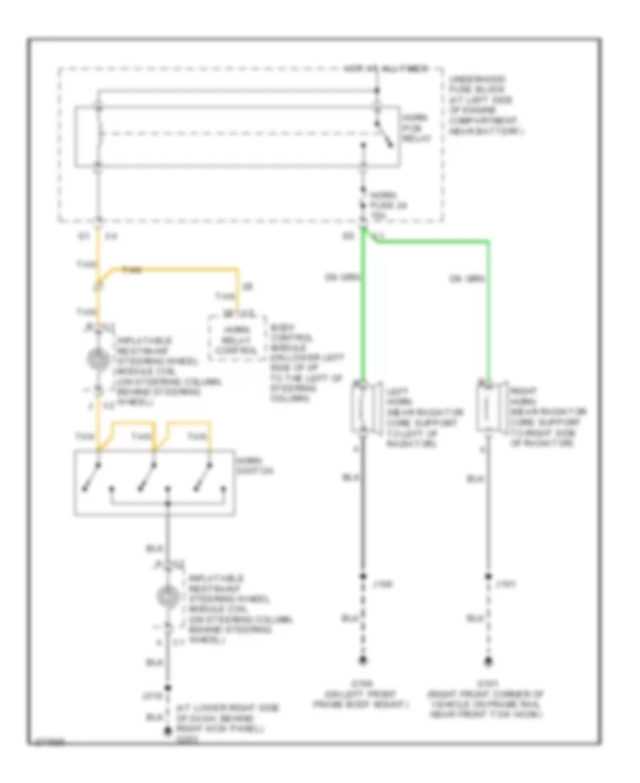
HORN
Horn Wiring Diagram for Hummer H2 2008
 https://portal-diagnostov.com/license.html
Automotive Electricians Portal FZCO
Automotive Electricians Portal FZCO
https://portal-diagnostov.com/license.html
https://portal-diagnostov.com/license.html
Automotive Electricians Portal FZCO
Automotive Electricians Portal FZCOList of elements for Horn Wiring Diagram for Hummer H2 2008:
- (at lower right side of dash, behind right kick panel) g203
- A x1
- B x1
- Body control module (on lower left side of i/p to the left of steering column)
- G100 (on left front frame body mount)
- G101 (right front corner of vehicle on frame rail near front tow hook)
- Horn fuse 24 15a
- Horn pcb relay
- Horn relay control
- Horn switch
- Hot at all times
- Inflatable restraint steering wheel module coil (on steering column, behind steering wheel)
- J x2
- J100
- J101
- J218
- K x2
- Left horn (near radiator core support to left of radiator)
- Right horn (near radiator core support to right side of radiator)
- Tan
- Underhood fuse block (at left side of engine compartment, near battery)
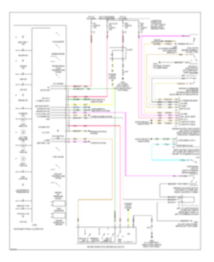
INSTRUMENT CLUSTER
Instrument Cluster Wiring Diagram for Hummer H2 2008
 https://portal-diagnostov.com/license.html
Automotive Electricians Portal FZCO
Automotive Electricians Portal FZCO
https://portal-diagnostov.com/license.html
https://portal-diagnostov.com/license.html
Automotive Electricians Portal FZCO
Automotive Electricians Portal FZCOList of elements for Instrument Cluster Wiring Diagram for Hummer H2 2008:
- 4wd ind
- 5v ref 1
- Abs ind
- Air bag ind
- Air bag off ind
- Air bag on ind
- Aux hvac ign fuse 41 10a
- Body control module (bcm) (on lower left side of i/p to the left of steering column)
- Brake fluid level switch (mounted to lower left side of master cylinder)
- Brake ind
- Charging ind
- Clock
- Computer data lines system
- Coolant temperature gauge
- Cruise ind
- Dic menu sw
- Dic sw sig
- Driver information center
- Driver information center (dic) switch
- Ecm ign fuse 47 15a
- Engine control module (ecm) (left front of engine compt below battery & fuse block underhood)
- Engine controls system
- Engine oil level switch (on lower right side of oil pan)
- Engine oil pressure (eop) sensor (on rear side of engine block behind intake manifold)
- Engine oil pressure gauge
- Eop sw sig
- Fluid level sig
- Fog lamps ind
- Fuel gauge
- Fuel level sens
- Fuel pump & sender assembly (in fuel tank)
- G103 (on front of right cylinder head)
- G200 (on left side of dash, behind left kick panel)
- G203 (at lower right side of dash, behind right kick panel)
- Gnd
- Hi spd data bus+
- Hi spd data bus-
- High beam ind
- Hot at all times
- Hot w/ run/crnk relay energized
- Ign volt
- Instrument panel cluster (ipc)
- Interior lights system
- Ipc fuse 39 10a
- J215
- J403 (in chassis harness 39 cm from g401 breakout)
- Left i/p junction block (lower left side of instrument panel to left of steering column)
- Left turn ind
- Lo ref
- Lo serial data
- Lo spd serial data
- Lo washer ind
- Logic
- Low engine oil pressure ind
- Low ref
- Low tire pressure ind
- Malfunction ind
- Mil ctrl
- Nca
- Oil pressure sens
- Park brake switch (part of parking brake assembly)
- Park brk sw sig
- Persona- lization
- Pnk
- Rdo fuse 36 15a
- Right turn ind
- Seat belt ind
- Security ind
- Set/ reset
- Speedometer
- Tachometer
- Tan
- Tow/haul ind
- Transmission fluid temperature gauge
- Trip/ fuel
- Trip/ odometer
- Underhood fuse block (at left side of engine compt, near battery)
- Vehicle info
- Voltmeter
- Vsc ind
- Warning system
- Wiper/washer system
INTERIOR LIGHTS
Courtesy Lamps Wiring Diagram for Hummer H2 2008
 https://portal-diagnostov.com/license.html
Automotive Electricians Portal FZCO
Automotive Electricians Portal FZCO
https://portal-diagnostov.com/license.html
https://portal-diagnostov.com/license.html
Automotive Electricians Portal FZCO
Automotive Electricians Portal FZCOList of elements for Courtesy Lamps Wiring Diagram for Hummer H2 2008:
- (on left side of dash, behind left kick panel) g200
- (on passenger side rear of body near d-pillar behind trim panel)
- 2nd row courtesy/ reading lamps
- 3rd row courtesy/ reading lamps (suv)
- Ajar sw sig
- Battery positive volt
- Bcm fuse 10a
- Body control module (bcm) (on lower left side of dash, to the left of steering column)
- Center console compartment lamp
- Center console compartment lamp switch (floor console components)
- Computer data lines system
- Courtesy lp ctrl
- Dome
- Driver door courtesy lamp
- Driver door latch (inside driver door below outside door handle)
- Driver door lock/ window switch
- G203 (at lower right side of dash, behind right kick panel)
- G302 (in left "b" pillar behind trim panel)
- G306 (in right "b" pillar behind trim panel)
- G410
- Gnd
- Headlamp & panel dimmer switch
- Hot at all times
- I/p fuse block (on lower left side of i/p, behind access panel)
- Inadvertent pwr ctrl
- Interior lp def sw sig
- J217
- J221 (in i/p harness, 10 cm from x205 breakout)
- J300 (in headliner harness, at top of left a-pillar near corner of windshield)
- J301
- J321
- J341 (in body harness, 5 cm from inflatable restraint sensing & diagnostic module breakout)
- J351
- J410
- J720
- J820
- Key sw sig
- Left i/p junction block (lower left side of instrument panel to left of steering column)
- Left rear door courtesy lamp
- Left rear door latch assembly (at rear of door)
- Left sunshade
- Lp ctrl
- Lr door ajar sw sig
- Nca
- Overhead console courtesy/ reading lamps
- Passenger door courtesy lamp
- Passenger door latch assembly (inside passenger door below outside door handle)
- Passenger door lock/ window switch
- Reading
- Right rear door courtesy lamp
- Right rear door latch assembly (at rear of door)
- Right sunshade
- Rr door ajar sw sig
- Serial data
- X10
- X12
Instrument Illumination Wiring Diagram for Hummer H2 2008
 https://portal-diagnostov.com/license.html
Automotive Electricians Portal FZCO
Automotive Electricians Portal FZCO
https://portal-diagnostov.com/license.html
https://portal-diagnostov.com/license.html
Automotive Electricians Portal FZCO
Automotive Electricians Portal FZCOList of elements for Instrument Illumination Wiring Diagram for Hummer H2 2008:
- (at lower right side of dash, behind right kick panel) g203
- (in i/p harness in window switch - global breakout, 10 cm from breakout) j278
- (not used)
- (on lower left side of dash, to the left of steering column) body control module (bcm)
- (on steering column, behind steering wheel) inflatable restraint steering wheel module coil
- 12v ref
- 12v ref x3
- Air suspension control module (center rear of vehicle, in front of trailer hitch)
- Auto
- Battery positive volt
- Bcm fuse 10a
- Clock
- Computer data lines system
- Driver information center (dic) switch
- G200 (on left side of dash, behind left kick panel)
- G203 (at lower right side of dash, behind right kick panel)
- G302 (in left "b" pillar behind trim panel)
- G306 (in right "b" pillar behind trim panel)
- Global window switch
- Head
- Headlamp & panel dimmer switch
- Horn switch
- Hot at all times
- Hvac control module
- I/p fuse block (on lower left side of i/p, behind access panel)
- I/p multi- function switch
- If equipped
- Ind dimming ctrl
- Instrument panel cluster (ipc)
- Instrument panel lps
- J215
- J216
- J217
- J218
- J225
- J321
- J351
- J720
- J820
- K2 x2
- Left i/p junction block (lower left side of instrument panel to left of steering column)
- Left rear window switch
- Left steering wheel control switch
- Lk ind ctrl 4 lo ind ctrl 4 hi ind ctrl 4 wd ind ctrl x2
- Lo spd gmlan ser data
- Logic
- M3 x1
- Midgate window switch (sut)
- Nca
- Nca ind ctrl
- Off
- Park
- Pnk
- Prk lp sw sig x2
- Prndl lamp
- Radio
- Rear window wiper/washer switch
- Right rear window switch
- Right steering wheel control switch
- Serial data
- Stop lamp switch (on top of brake pedal bracket)
- Sunroof switch (if equipped)
- Swc bklt fuse 2a
- Transfer case shift control module (behind headlight switch)
- Transfer case shift control switch
- W/ heated w/s washer
- W/ offroad suspension chassis package
- Winshield washer solvent heater (left rear corner of engine compt)
- X1 p3
- X10
- X11
MEMORY SYSTEMS
Driver"s Memory Seat Wiring Diagram (1 of 2) for Hummer H2 2008
 https://portal-diagnostov.com/license.html
Automotive Electricians Portal FZCO
Automotive Electricians Portal FZCO
https://portal-diagnostov.com/license.html
https://portal-diagnostov.com/license.html
Automotive Electricians Portal FZCO
Automotive Electricians Portal FZCOList of elements for Driver"s Memory Seat Wiring Diagram (1 of 2) for Hummer H2 2008:
- (in right "b" pillar behind trim panel) g306
- (not used)
- 12v ref
- B+ volt
- Computer data lines system
- Ddm fuse 15a
- Down
- Driver seat 2 circuit breaker cb3 25a
- Driver seat adjuster switch
- Driver seat lumbar switch
- Dsm fuse 10a
- Fwd
- G200 (on left side of dash, behind left kick panel)
- Gnd
- Horz fwd sw sig
- Horz rwd sw sig
- Hot at all times
- I/p fuse block (on lower left side of i/p, behind access panel)
- J312
- J382
- Left i/p junction block (lower left side of instrument panel to left of steering column)
- Low ref
- Lumbar dw sw sig
- Lumbar fwd sw sig
- Lumbar rwd sw sig
- Lumbar up sw sig
- Memory seat module (msm) (under driver seat)
- Pnk
- Recline fwd sw sig
- Recline rwd sw sig
- Rwd
- Seats system
- Serial data
- Tan
- Vert dn sw sig
- Vert up sw sig
- X12
Driver"s Memory Seat Wiring Diagram (2 of 2) for Hummer H2 2008
 https://portal-diagnostov.com/license.html
Automotive Electricians Portal FZCO
Automotive Electricians Portal FZCO
https://portal-diagnostov.com/license.html
https://portal-diagnostov.com/license.html
Automotive Electricians Portal FZCO
Automotive Electricians Portal FZCOList of elements for Driver"s Memory Seat Wiring Diagram (2 of 2) for Hummer H2 2008:
- (in body harness, 5 cm from inflatable restraint sensing & diagnostic module breakout) j341
- (in driver seat back, on left) driver seat lumbar horizontal motor
- (in driver seat back, on right) driver seat lumbar vertical motor
- (lower right side of driver seat back, below seat back) driver seat recline motor
- 12v ref
- 5v ref
- Back temp sens sig
- Computer data lines system
- Cushion element ctrl
- Cushion temp sig
- Driver door lock/ window switch
- Driver memory/ heated seat switch
- Driver seat adjuster motor assembly (below driver seat mounted to seat track)
- Driver seat lumbar horizontal motor position sensor (in driver seat back, on left)
- Driver seat lumbar vertical motor position sensor (in driver seat back, on right)
- Driver seat recline position sensor (lower right side of driver seat back, below seat back upholstery)
- Drv back element ctrl
- Exit
- Gnd
- Horz mtr fwd ctrl
- Horz mtr rwd ctrl
- Horz mtr sens sig
- J309
- J310 (in body harness, 14 cm from g301 breakout)
- J340 (in body harness, 10 cm from seat belt pretensioner - driver breakout) tan
- Lumbar horz sens sig
- Lumbar mtr dn ctrl
- Lumbar mtr fwd ctrl
- Lumbar mtr rwd ctrl
- Lumbar mtr up ctrl
- Lumbar vert sens sig
- Memory seat module (msm) (under driver seat)
- Memory set sw sig
- Pass back element ctrl
- Pnk
- Recline mtr fwd ctrl
- Recline mtr rwd ctrl
- Recline mtr sens sig
- Seats system
- Serial data
- Tan
- Vert mtr dn ctrl
- Vert mtr sens sig
- Vert mtr up ctrl
Memory Mirrors Wiring Diagram for Hummer H2 2008
 https://portal-diagnostov.com/license.html
Automotive Electricians Portal FZCO
Automotive Electricians Portal FZCO
https://portal-diagnostov.com/license.html
https://portal-diagnostov.com/license.html
Automotive Electricians Portal FZCO
Automotive Electricians Portal FZCOList of elements for Memory Mirrors Wiring Diagram for Hummer H2 2008:
- (at lower right side of dash, behind right kick panel) g203
- (right side of dash behind end trim panel) right i/p junction block
- 12v ref
- 4a7
- 5v ref
- Computer data lines system
- Ddm fuse 15a
- Down
- Driver door lock/ window switch
- Driver memory/ heated seat switch
- Driver outside rearview mirror
- Electro- chromic mirror
- Element ctrl
- Exit
- Extend
- G200 (on left side of dash, behind left kick panel)
- Gnd
- Horz position ctrl
- Horz position sens sig
- Hot at all times
- I/p fuse block (on lower left side of i/p, behind access panel)
- J501
- J502
- J601
- J602
- Left
- Left select
- Low ref
- Mirrors system
- Mtr common
- Mtr extend ctrl
- Mtr retract ctrl
- Passenger door lock/ window switch
- Passenger outside rearview mirror
- Pdm fuse 15a
- Pnk
- Retract
- Right
- Right select
- Serial data
- Sw sig
- Switch pwr
- Vert position ctrl
- Vert position sens sig
NAVIGATION
Navigation Wiring Diagram for Hummer H2 2008
 https://portal-diagnostov.com/license.html
Automotive Electricians Portal FZCO
Automotive Electricians Portal FZCO
https://portal-diagnostov.com/license.html
https://portal-diagnostov.com/license.html
Automotive Electricians Portal FZCO
Automotive Electricians Portal FZCOList of elements for Navigation Wiring Diagram for Hummer H2 2008:
- (not used)
- Audio w/ dvd navigation
- Coax
- Computer data lines system
- Electronic brake control module (ebcm) (left rear of engine compt behind fuse block-underhood to left of brake fluid reservoir)
- G302 (in left "b" pillar behind trim panel)
- Gnd
- Hot at all times
- J201
- Left i/p junction block (lower left side of instrument panel to left of steering column)
- Lo serial data
- Navigation antenna
- Navigation antenna (at top left front of roof)
- Radio
- Rdo fuse 36 15a
- Underhood fuse block (at left side of engine compt, near battery)
- Vehicle spd sig
- Vss
- X12
Rear Camera Wiring Diagram for Hummer H2 2008
 https://portal-diagnostov.com/license.html
Automotive Electricians Portal FZCO
Automotive Electricians Portal FZCO
https://portal-diagnostov.com/license.html
https://portal-diagnostov.com/license.html
Automotive Electricians Portal FZCO
Automotive Electricians Portal FZCOList of elements for Rear Camera Wiring Diagram for Hummer H2 2008:
- Audio w/ dvd navigation
- Body control module (bcm) (on lower left side of i/p to the left of steering column)
- Camera vid sig +
- Computer data lines system
- Drain wire
- Exterior lights system
- G302 (in left "b" pillar behind trim panel)
- Hot w/ run/ crank relay energized
- Inside rearview mirror (isrvm)
- J222 (in i/p harness, 5 cm from engine compt pass through)
- Lamp rly ctrl
- Left i/p junction block (lower left side of instrument panel to left of steering column)
- Lo serial data
- Misc ign fuse 37 10a
- Nca
- Nca lamp rly ctrl nca drain wire nca camera gnd nca camera ctrl nca camera vid sig + nca camera vid sig +
- Pnk
- Radio
- Rearview camera (center of rear bumper above trailer hitch receiver)
- Sound systems
- Underhood fuse block (at left side of engine compt, near battery)
- X12
POWER DISTRIBUTION
Power Distribution Wiring Diagram (1 of 4) for Hummer H2 2008
 https://portal-diagnostov.com/license.html
Automotive Electricians Portal FZCO
Automotive Electricians Portal FZCO
https://portal-diagnostov.com/license.html
https://portal-diagnostov.com/license.html
Automotive Electricians Portal FZCO
Automotive Electricians Portal FZCOList of elements for Power Distribution Wiring Diagram (1 of 4) for Hummer H2 2008:
- (at left side of engine compt, near battery) underhood fuse block
- (in chassis harness, 8 cm from fuse block underhood x3 breakout) j110
- (in infotainment harness in x350 breakout, 6 cm from main harness) j201
- (not used)
- (part of positive battery cable assembly) battery cable junction block
- 200a
- A5 x3
- Air bag batt fuse 38 15a
- Air suspension control module
- Air suspension relay
- Amp fuse 35 30a
- Audio amplifier
- Automatic transmission
- Battery
- Bck/up lamp pcb relay
- Blower motor control module
- Body control module (bcm)
- C1 x3
- Clock
- D2 x2
- Data link connector (dlc)
- Digital radio receiver (if equipped)
- Dlis fuse 29 2a
- Drl pcb relay
- E1 x5
- E2 x4
- Ecas fuse 32 15a
- Ecas fuse 51 60a
- Ecm batt fuse 10 10a
- Electronic brake control module (ebcm)
- Engine control module (ecm)
- Evaporative emission (evap) canister vent solenoid valve
- Front accessory power outlet
- Frt wash pcb relay
- Fuel fuse 18 20a
- Fuel pump flow control module
- Fuse
- G203 (at lower right side of dash, behind right kick panel)
- G3 x4
- Generator
- Hdlp lo relay
- Hi beam pcb relay
- Horn pcb relay
- Hvac batt fuse 33 10a
- Hvac blwr fuse 61 40a
- Hvac control module
- Inflatable restraint sensing & diagnostic module (sdm)
- Inflatable restraint vehicle roller sensor
- Instrument panel cluster (ipc)
- Ipc fuse 39 10a
- J351
- Lbec 1 fuse 56 60a
- Lbec 2 fuse 62 60a
- Left i/p junction block (lower left side of dash to left of steering column)
- Ltr fuse 44 15a
- Mbec 1 fuse 60 60a
- N3 x2
- Prk lamp relay
- Radio
- Rdo fuse 36 15a
- Rear defog relay
- Rear seat audio (rsa) control
- Rear wash pcb relay
- Red
- Right i/p junction block (right side of dash, behind end trim panel)
- S/roof fuse 28 30a
- Seo b1 fuse 43 15a
- Seo b2 fuse 31 30a
- Starter
- Starter relay
- Stud 1 trlr fuse 59 40a
- Stud 2 trlr fuse 55 30a
- Sunroof module (if equipped)
- Tcm batt fuse 12 15a
- To i/p fuse block (diagram 2 of 4)
- To left i/p junction block (diagram 2 of 4)
- To run/accy pcb relay (diagram 3 of 4)
- To splice j212 (diagram 4 of 4)
- Trailer connector
- Transfer case shift control module
- Trec fuse 58 30a
- Trlr stop lt pcb relay
- Trlr stop rt pcb relay
- Vses/ abs 1 fuse 52 60a
- Vses/ abs 2 fuse 7 30a
- W/ heated w/s washer
- W/ off road suspension chassis package
- Windshield washer solvent heater
- Wiper control pcb relay
- Wiper speed pcb relay
- Wpr fuse 30 25a
- Wsw/htr fuse 57 60a
- X11
- X2 b1
- X2 d3
- X3 b3
- X3 e4
- X4 e1
- X4 j1
- X5 b2
- X5 d1
- X5 f2
- X6 a
Power Distribution Wiring Diagram (2 of 4) for Hummer H2 2008
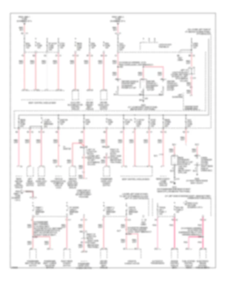 https://portal-diagnostov.com/license.html
Automotive Electricians Portal FZCO
Automotive Electricians Portal FZCO
https://portal-diagnostov.com/license.html
https://portal-diagnostov.com/license.html
Automotive Electricians Portal FZCO
Automotive Electricians Portal FZCOList of elements for Power Distribution Wiring Diagram (2 of 4) for Hummer H2 2008:
- (at left side of engine compt, near battery) underhood fuse block
- (in chassis harness, 20 cm from air suspension relay main harness breakout) j356
- (in console harness, 16 cm from console bin lamp breakout) j352
- (lower left side of dash, to left of steering column) left i/p junction block
- (not used)
- (on lower left side of i/p, behind access panel) i/p fuse block
- A1 x4
- A7 x3
- Automatic transmission
- Aux pwr 2 fuse 20a
- Aux pwr fuse 20a
- Auxiliary blower motor control module
- B1 x2
- B4 x4
- B7 x2
- Bcm fuse 10a
- Body control module (bcm)
- Cargo accessory power outlet (right rear side of cargo box)
- Center console 1 accessory power outlet
- Center console 2 accessory power outlet
- Center console compartment accessory power outlet
- Ctsy fuse 15a
- D1 x1
- Ddm fuse 15a
- Dim fuse 10a
- Driver door lock/ window switch
- Driver memory seat module
- Dseat 2 circuit breaker 25a
- Dsm fuse 15a
- Ecm ign fuse 47 15a
- Electronic brake control module (ebcm)
- Engine control module (ecm)
- F5 x3
- From c mbec 1 fuse (diagram 1 of 4)
- From hvac ign fuse (diagram 4 of 4)
- From lbec 1 fuse (diagram 1 of 4)
- From lbec 2 fuse (diagram 1 of 4)
- Fuel system control module (fscm)
- G203 (at lower right side of dash, behind right kick panel)
- G405 (at right rear frame body mount)
- G410 (on passenger side rear of body near d-pillar behind trim panel)
- Garage door opener (gdo)
- Info fuse 15a
- Int lts fuse 10a
- J31
- J410
- Left i/p junction block (lower left side of dash to left of steering column)
- Left rear window switch
- Left sunshade
- Lock/unlock pcb relay
- Lt dr circuit breaker 25a
- Lt stop turn fuse 15a
- Mgate circuit breaker 25a
- Midgate window motor
- Onstar fuse 10a
- P5 x2
- Passenger door lock/ window switch
- Passenger seat adjuster switch
- Passenger seat lumbar adjuster switch
- Pdm fuse 15a
- Pnk
- Pseat 1 circuit breaker 25a
- Rear accessory power outlet (mounted in the trim panel below right d-pillar)
- Rear heated seat control module
- Rear hvac fuse 30a
- Rear seat fuse 20a
- Rear window wiper control module
- Rear wiper fuse 25a
- Remote control door lock receiver (rcdlr)
- Right i/p junction block (right side of dash behind end trim panel)
- Right rear window switch
- Rt doors circuit breaker 25a
- Rt stop turn fuse 15a
- Stop lamp fuse 15a
- Sut
- Suv
- Trans ign 1 fuse 17 15a
- Ugdo fuse 10a
- Vehicle communication interface module (vcim)
- Video display (w/ rear seat entertainment package)
- W/ onstar
- X1 3b2
- X1 3b4
- X1 f1
- X1 g2
- X1 j2
- X10
- X11
- X12
- X2 a4
- X2 b5
- X3 b2
- X3 b4
Power Distribution Wiring Diagram (3 of 4) for Hummer H2 2008
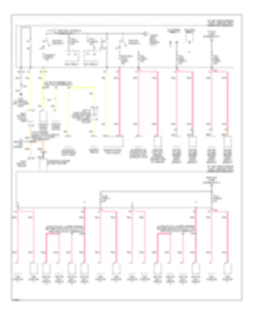 https://portal-diagnostov.com/license.html
Automotive Electricians Portal FZCO
Automotive Electricians Portal FZCO
https://portal-diagnostov.com/license.html
https://portal-diagnostov.com/license.html
Automotive Electricians Portal FZCO
Automotive Electricians Portal FZCOList of elements for Power Distribution Wiring Diagram (3 of 4) for Hummer H2 2008:
- (at left side of engine compt, near battery) underhood fuse block
- (in i/p harness in body control module breakout, 5 cm from jx205 breakout) j230
- (in ignition coil jumper harness, between ignition coils 4 & 2, 3 cm from ignition coil 4 breakout) j160
- (in ignition coil jumper harness, between ignition coils 5 & 7, 3 cm from ignition coil 5 breakout) j140
- (in the i/p harness, 5 cm from the x205 breakout) j220
- A/c cmprsr relay
- Automatic transmission shift lever
- Body control module (bcm)
- D4 x5
- Ecm/throt cntrl fuse 3 15a
- Eng fuse 2 15a
- Engine control module (ecm)
- Evaporative emission (evap) canister vent solenoid valve
- Fan 1 fuse 50 40a
- Fan 2 fuse 53 40a
- Fan cntrl relay
- Fan hi relay
- Fan lo relay
- From o2-b fuse (diagram 3 of 4)
- From prk lamp relay (diagram 1 of 4)
- Fuel injector
- G104 (at rear of left cylinder head)
- Heated oxygen sensor (ho2s) bank 1 sensor 1
- Heated oxygen sensor (ho2s) bank 1 sensor 2
- Heated oxygen sensor (ho2s) bank 2 sensor 1
- Heated oxygen sensor (ho2s) bank 2 sensor 2
- Hvac control module
- Ignition coil/ module
- Inj a fuse 20 20a
- Inj b fuse 11 20a
- J102
- Left i/p junction block (lower left side of dash to left of steering column)
- Mass air flow (maf) sensor/ intake air temperature (iat) sensor
- Midgate window motor
- Midgate window switch
- Nca
- O2-a snsr fuse 16 10a
- O2-b snsr fuse 6 10a
- Pnk
- Pwr/trn pcb relay
- Run/accy fuse 40 10a
- Run/accy pcb relay
- Sunroof module
- Sut
- To inj-a fuse (diagram 3 of 4)
- To run/ crnk relay (diagram 4 of 4)
- W/ heated w/s washer
- Windshield washer solvent heater
- X2 n5
Power Distribution Wiring Diagram (4 of 4) for Hummer H2 2008
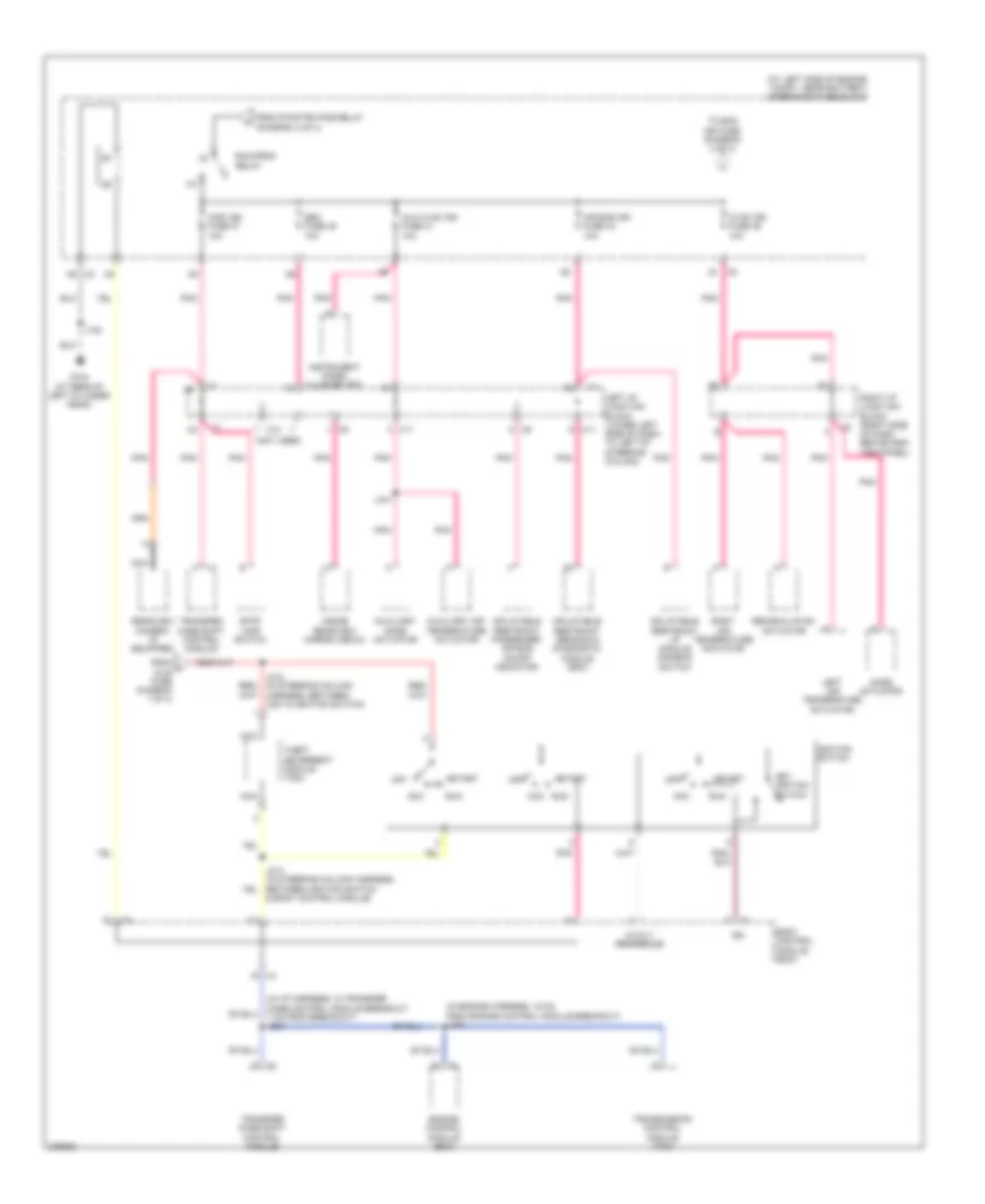 https://portal-diagnostov.com/license.html
Automotive Electricians Portal FZCO
Automotive Electricians Portal FZCO
https://portal-diagnostov.com/license.html
https://portal-diagnostov.com/license.html
Automotive Electricians Portal FZCO
Automotive Electricians Portal FZCOList of elements for Power Distribution Wiring Diagram (4 of 4) for Hummer H2 2008:
- & body control module)
- (at left side of engine compt, near battery) underhood fuse block
- (in engine harness, 16 cm from engine control module breakout) j130
- (in i/p harness, in transfer case control module breakout, 7 cm from breakout) j234
- (not used)
- 5-volt reference
- Acc
- Air bag ign fuse 34 10a
- Aux hvac ign fuse 41 10a
- Auxiliary air temperature actuator
- Auxiliary mode actuator
- Body control module (bcm)
- Engine control module (ecm)
- From h dlis fuse diagram 1 of 4)
- From pwr/trn pcb relay (diagram 3 of 4)
- G104 (at rear of left cylinder head)
- Hvac ign fuse 46 10a
- Ign
- Ignition switch
- Inflatable restraint i/p module disable switch
- Inflatable restraint passenger air bag on/off indicator
- Inflatable restraint sensing & diagnostic module (sdm)
- Inside rearview mirror (isrvm)
- Instrument panel cluster (ipc)
- J102
- J441
- Key ignition switch
- Left air temperature actuator
- Left i/p junction block (lower left side of dash to left of steering column)
- Misc ign fuse 37 10a
- Mode actuator
- N5 x2
- Nca
- Off
- Pnk
- Rearview camera (if equipped)
- Recirculation actuator
- Right air temperature actuator
- Right i/p junction block (right side of dash behind end trim panel)
- Run
- Run/crnk relay
- Seo fuse 45 10a
- Start
- Stop lamp switch
- Theft deterrent module (tdm)
- To ecm ign fuse (diagram 2 of 4)
- Transfer case shift control module
- Transmission control module (tcm)
- X11
- X12
POWER DOOR LOCKS
Power Door Locks Wiring Diagram for Hummer H2 2008
 https://portal-diagnostov.com/license.html
Automotive Electricians Portal FZCO
Automotive Electricians Portal FZCO
https://portal-diagnostov.com/license.html
https://portal-diagnostov.com/license.html
Automotive Electricians Portal FZCO
Automotive Electricians Portal FZCOList of elements for Power Door Locks Wiring Diagram for Hummer H2 2008:
- (on lower left side of i/p, behind access panel) i/p fuse block
- 3b2
- 3b4
- 4a7
- Ajar sw sig
- Aux hvac ign fuse 41 10a
- Batt pos
- Batter
- Body control module (bcm) (on lower left side of i/p to the left of steering column)
- Closed sw sig
- Coax
- Computer data lines system
- Data bus+
- Data bus-
- Ddm fuse 15a
- Driver door latch (inside driver door below outside door handle)
- Driver door lock/window switch
- G103 (on front of right cylinder head)
- G200 (on left side of dash, behind left kick panel)
- G203 (at lower right side of dash, behind right kick panel)
- Gmlan serial data
- Ground
- Hood ajar switch (part of hood latch assembly)
- Hot at all times
- Hot w/ run/crank relay energized
- I/p fuse block (on lower left side of i/p, behind access panel)
- Ign
- Info fuse 5a
- Instrument panel cluster (ipc)
- J217
- Keyless entry antenna
- Lck 1 fuse 15a
- Lck 2 fuse 15a
- Left i/p junction block (lower left side of instrument panel to left of steering column)
- Left i/p junction block (lower left side x1
- Left rear door latch (at left rear of door)
- Liftgate door lock actuator (at lower center of liftgate)
- Lock ctrl
- Lock sw sig
- Logic
- Lt dr circuit breaker 25a
- Nca
- Of instrument panel to left of steering column)
- Passenger door latch (inside passenger door below outside door handle)
- Passenger door lock/window switch
- Pdm fuse 15a
- Pnk
- Rear door lock/unlock pcb relay
- Remote control door lock receiver (rcdlr) (center of instrument panel below trim panel to left of clock)
- Right i/p junction block (right side of i/p behind end trim panel)
- Right rear door latch (at right rear of door)
- Rt doors circuit breaker cb2 25a
- Security ind
- Serial data
- Suv
- Tan
- Underhood fuse block (at left side of engine compt, near battery)
- Unlck 1 fuse 15a
- Unlck 2 fuse 15a
- Unlock control
- Unlock ctrl
- Volt
POWER MIRRORS
Power Mirrors Wiring Diagram for Hummer H2 2008
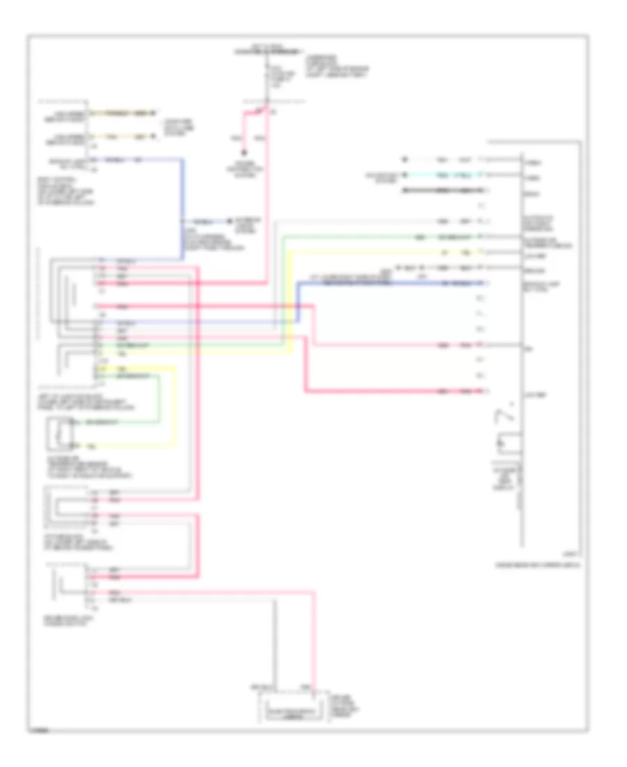 https://portal-diagnostov.com/license.html
Automotive Electricians Portal FZCO
Automotive Electricians Portal FZCO
https://portal-diagnostov.com/license.html
https://portal-diagnostov.com/license.html
Automotive Electricians Portal FZCO
Automotive Electricians Portal FZCOList of elements for Power Mirrors Wiring Diagram for Hummer H2 2008:
- Automatic day/night mirror sig
- Aux hvac-ign fuse 41 10a
- Backup lamp rly ctrl
- Body control module (bcm) (on lower left side of i/p to the left of steering column)
- Computer data lines system
- Drain
- Driver door lock/ window switch
- Driver outside rearview mirror
- Electrochromic mirror
- Exterior lights system
- G203 (at lower right side of dash, behind right kick panel)
- Ground
- High speed ser data bus+
- High speed ser data bus-
- Hot w/ run/ crank relay energized
- I/p fuse block (on lower left side of i/p, behind access panel)
- Ign
- Inside rearview mirror (isrvm)
- J222 (in i/p harness, 5 cm from engine compt pass through)
- J301
- Left i/p junction block (lower left side of instrument panel to left of steering column)
- Logic
- Low ref
- Navigation system
- Nca
- Outside air temp display
- Outside air temperature sensor (at right front of vehicle, to right of radiator support)
- Outside air temperature sig
- Pnk
- Power distribution system
- Tan
- Underhood fuse block (at left side of engine compt, near battery)
- Video+
- Video-
- X10
POWER SEATS
Front Heated Seats Wiring Diagram (1 of 2) for Hummer H2 2008
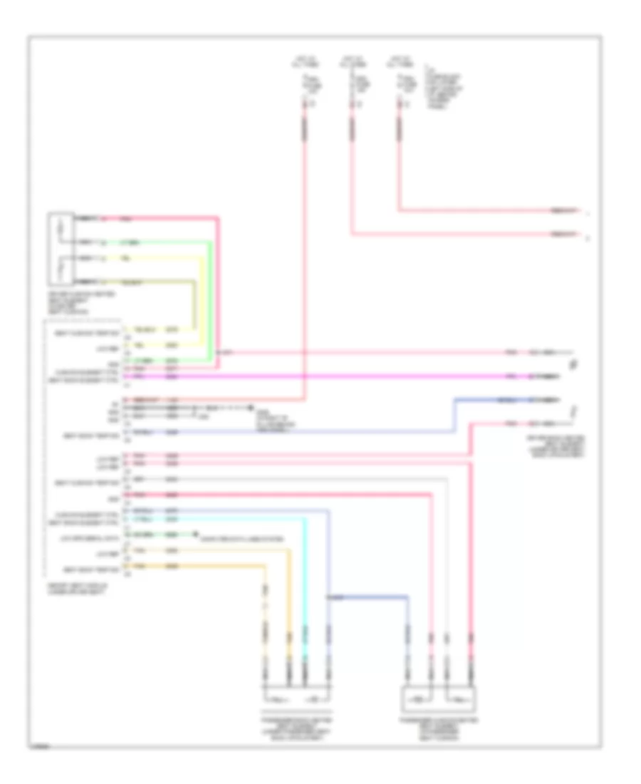 https://portal-diagnostov.com/license.html
Automotive Electricians Portal FZCO
Automotive Electricians Portal FZCO
https://portal-diagnostov.com/license.html
https://portal-diagnostov.com/license.html
Automotive Electricians Portal FZCO
Automotive Electricians Portal FZCOList of elements for Front Heated Seats Wiring Diagram (1 of 2) for Hummer H2 2008:
- Computer data lines system
- Cushion element ctrl
- Ddm fuse 15a
- Driver back heated seat element (under driver seat back upholstery)
- Driver cushion heated seat element (in driver seat cushion)
- Dsm fuse 10a
- G306 (in right "b" pillar behind trim panel)
- Gnd
- Gnd x3
- Hot at all times
- I/p fuse block (on lower left side of i/p, behind access panel)
- J311
- J316
- J382
- Low ref
- Low spd serial data
- Memory seat module (under driver seat)
- Nca
- Passenger back heated seat element (under passenger seat back upholstery)
- Passenger cushion heated seat element (in passenger seat cushion)
- Pdm fuse 15a
- Pnk
- Seat back element ctrl
- Seat back temp sig
- Seat cushion temp sig
- Tan
Front Heated Seats Wiring Diagram (2 of 2) for Hummer H2 2008
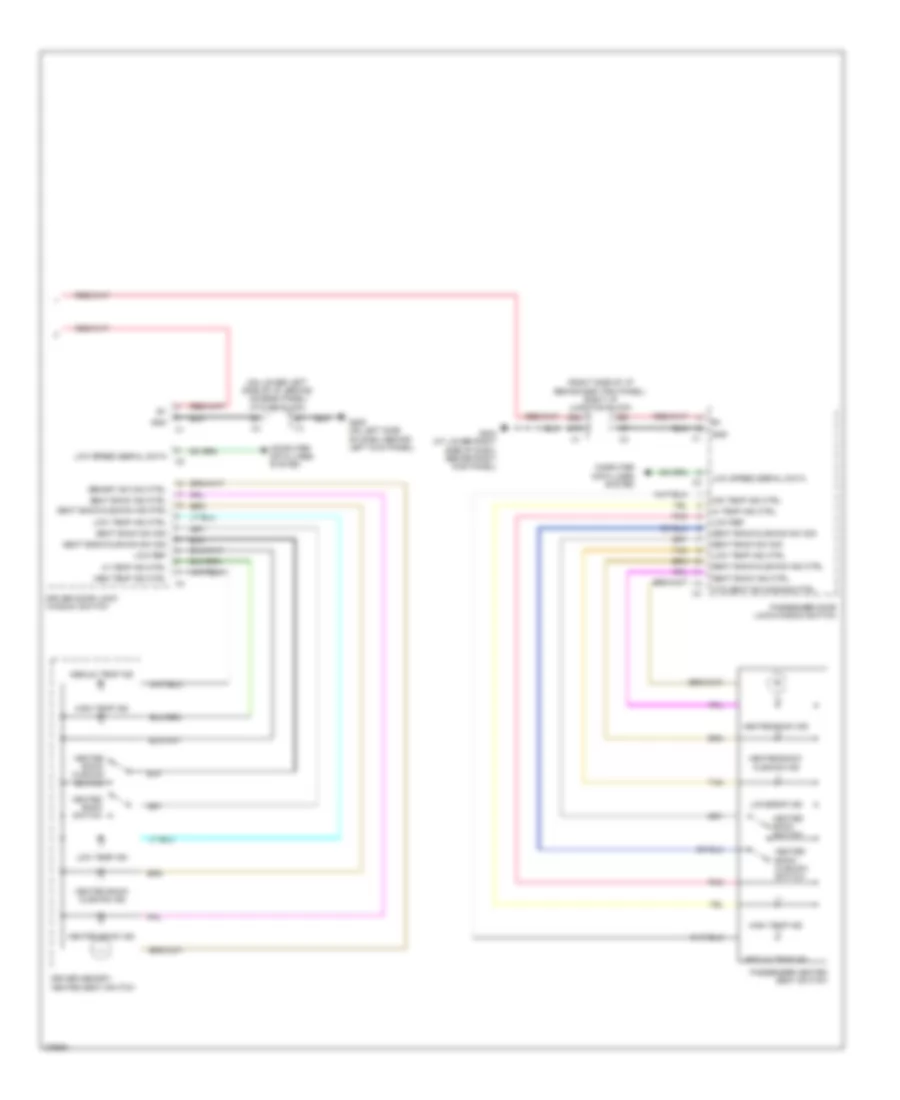 https://portal-diagnostov.com/license.html
Automotive Electricians Portal FZCO
Automotive Electricians Portal FZCO
https://portal-diagnostov.com/license.html
https://portal-diagnostov.com/license.html
Automotive Electricians Portal FZCO
Automotive Electricians Portal FZCOList of elements for Front Heated Seats Wiring Diagram (2 of 2) for Hummer H2 2008:
- (on lower left side of i/p, behind access panel) i/p fuse block
- (right side of i/p behind end trim panel) right i/p junction block
- 3b2
- 4a7
- Computer data lines system
- Cushion ind
- Driver door lock/ window switch
- Driver memory/ heated seat switch
- G200 (on left side of dash, behind left kick panel)
- G203 (at lower right side of dash, behind right kick panel)
- Gnd
- Heated back ind
- Heated back switch
- Heated back/
- Heated back/ cushion ind
- Heated back/ cushion switch
- Hi temp ind ctrl
- High temp ind
- Htd seat sw dimming ctrl
- Low ref
- Low speed serial data
- Low temp ind
- Low temp ind ctrl
- Med temp ind ctrl
- Medium temp ind
- Memory sw dim ctrl
- Mid temp ind ctrl
- Passenger door lock/window switch
- Passenger heated seat switch
- Pnk
- Seat back ind ctrl
- Seat back sw sig
- Seat back/cushion ind ctrl
- Seat back/cushion sw sig
- Tan
Passenger Power Seat Wiring Diagram for Hummer H2 2008
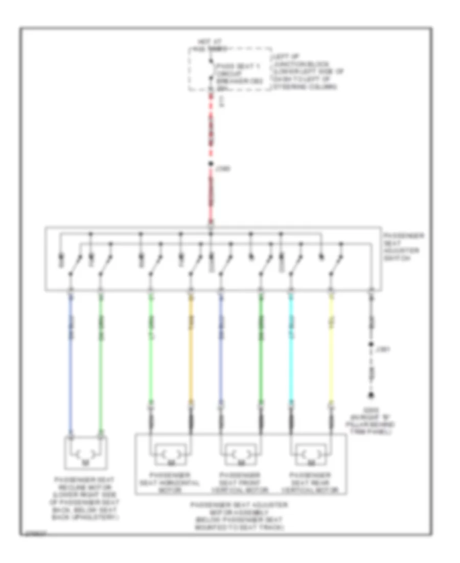 https://portal-diagnostov.com/license.html
Automotive Electricians Portal FZCO
Automotive Electricians Portal FZCO
https://portal-diagnostov.com/license.html
https://portal-diagnostov.com/license.html
Automotive Electricians Portal FZCO
Automotive Electricians Portal FZCOList of elements for Passenger Power Seat Wiring Diagram for Hummer H2 2008:
- Down
- Fwd
- G306 (in right "b" pillar behind trim panel)
- Hot at all times
- J380
- J381
- Left i/p junction block (lower left side of dash to left of steering column)
- Nca
- Pass seat 1 circuit breaker cb2 25a
- Passenger seat adjuster motor assembly (below passenger seat mounted to seat track)
- Passenger seat adjuster switch
- Passenger seat front vertical motor
- Passenger seat horizontal motor
- Passenger seat rear vertical motor
- Passenger seat recline motor (lower right side of passenger seat back, below seat back upholstery)
- Rwd
- Tan
- X11
Passenger"s Lumbar Wiring Diagram for Hummer H2 2008
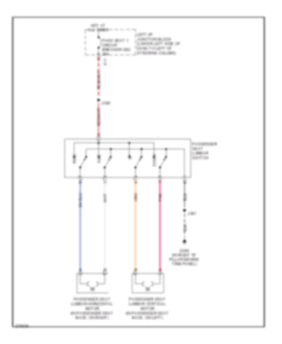 https://portal-diagnostov.com/license.html
Automotive Electricians Portal FZCO
Automotive Electricians Portal FZCO
https://portal-diagnostov.com/license.html
https://portal-diagnostov.com/license.html
Automotive Electricians Portal FZCO
Automotive Electricians Portal FZCOList of elements for Passenger"s Lumbar Wiring Diagram for Hummer H2 2008:
- Down
- Fwd
- G306 (in right "b" pillar behind trim panel)
- Hot at all times
- J380
- J381
- Left i/p junction block (lower left side of dash to left of steering column)
- Pass seat 1 circuit breaker cb2 25a
- Passenger seat lumbar horizontal motor (in passenger seat back, on right)
- Passenger seat lumbar switch
- Passenger seat lumbar vertical motor (in passenger seat back, on left)
- Pnk
- Rwd
- X11
Rear Heated Seats Wiring Diagram for Hummer H2 2008
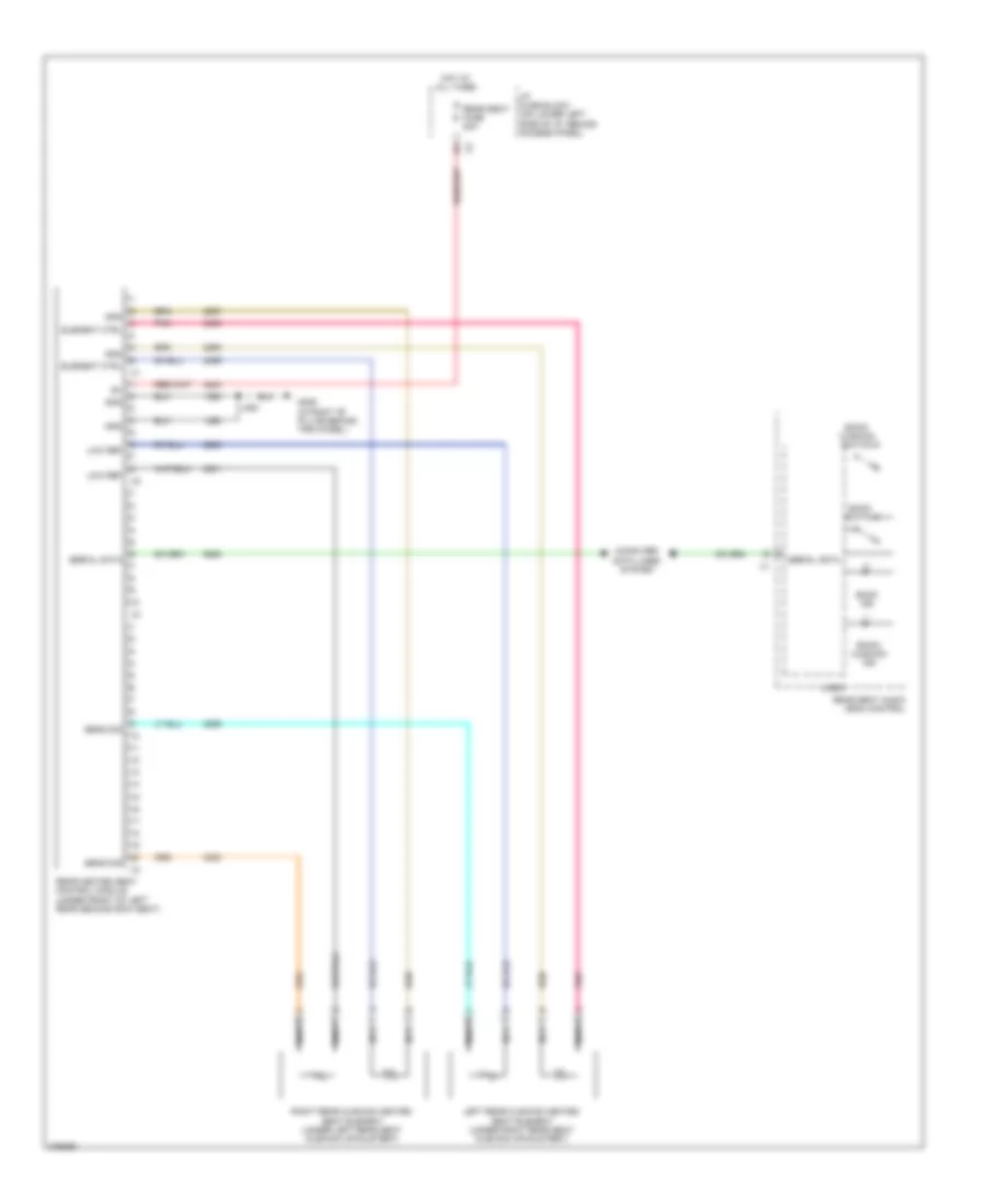 https://portal-diagnostov.com/license.html
Automotive Electricians Portal FZCO
Automotive Electricians Portal FZCO
https://portal-diagnostov.com/license.html
https://portal-diagnostov.com/license.html
Automotive Electricians Portal FZCO
Automotive Electricians Portal FZCOList of elements for Rear Heated Seats Wiring Diagram for Hummer H2 2008:
- Back ind
- Back switch
- Back/ cushion ind
- Back/ cushion switch
- Computer data lines system
- Element ctrl
- G306 (in right "b" pillar behind trim panel)
- Gnd
- Hot at all times
- I/p fuse block (on lower left side of i/p, behind access panel)
- J393
- Left rear cushion heated seat element (under right rear seat cushion upholstery)
- Logic
- Low ref
- Nca
- Pnk
- Rear heated seat control module (under front of left rear second row seat)
- Rear seat audio (rsa) control
- Rear seat fuse 20a
- Right rear cushion heated seat element (under left rear seat cushion upholstery)
- Sens sig
- Serial data
POWER TOP/SUNROOF
Power Top/Sunroof Wiring Diagram for Hummer H2 2008
 https://portal-diagnostov.com/license.html
Automotive Electricians Portal FZCO
Automotive Electricians Portal FZCO
https://portal-diagnostov.com/license.html
https://portal-diagnostov.com/license.html
Automotive Electricians Portal FZCO
Automotive Electricians Portal FZCOList of elements for Power Top/Sunroof Wiring Diagram for Hummer H2 2008:
- (at lower right side of dash, behind right kick panel) g203
- Batt positive volt
- G203 (at lower right side of dash, behind right kick panel)
- Ground
- Hot at all times
- Hot w/ run/ accy pcb relay energized
- Ignition voltage
- Interior lights system
- J215
- J220
- J321
- Left i/p junction block (lower left side of x8 instrument panel to left of steering column)
- Logic
- Run/accy fuse 40 10a
- S/roof fuse 28 30a
- Sunroof actuator motor
- Sunroof module (in front of headliner, near front overhead console)
- Sunroof sw close
- Sunroof sw open
- Sunroof switch
- Underhood fuse block (at left side of engine compartment, near battery)
POWER WINDOWS
Power Windows Wiring Diagram (1 of 2) for Hummer H2 2008
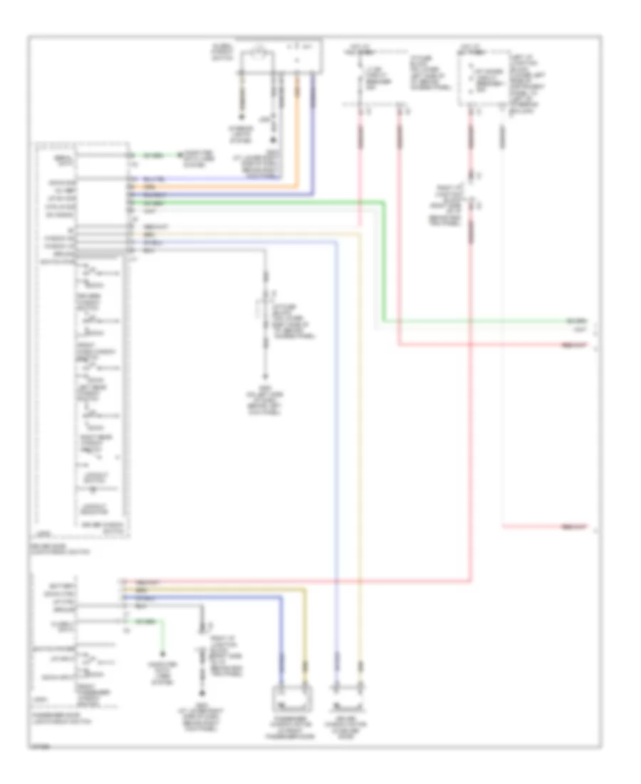 https://portal-diagnostov.com/license.html
Automotive Electricians Portal FZCO
Automotive Electricians Portal FZCO
https://portal-diagnostov.com/license.html
https://portal-diagnostov.com/license.html
Automotive Electricians Portal FZCO
Automotive Electricians Portal FZCOList of elements for Power Windows Wiring Diagram (1 of 2) for Hummer H2 2008:
- 12v ref
- 3b4
- 4a7
- Battery
- Class 2 data
- Computer data lines system
- Down
- Down ctrl
- Down input
- Down sig
- Driver door lock/window switch
- Driver window motor (in driver door)
- Driver window switch
- Drivers window switch
- Front pass window switch
- Front passenger window switch
- G200 (on left side of dash, behind left kick panel)
- G203 (at lower right side of dash, behind right kick panel)
- Global window switch
- Ground
- Hot at all times
- I/p fuse block (on lower left side of i/p, behind access panel)
- I/p fuse block (on lower x1 left side of i/p, behind access panel)
- Interior lights system
- Left i/p junction block (lower left side of instrument panel to left of steering column) x11
- Left rear window switch
- Lockout indicator
- Lockout switch
- Logic
- Lt dr circuit breaker 25a
- Mtr up sig
- Passenger door lock/window switch
- Passenger window motor (in front passenger door)
- Right i/p junction block (right side of i/p behind end trim panel)
- Right i/p junction block x1 (right side of i/p behind end trim panel)
- Right rear window switch
- Rt doors circuit breaker 1 25a
- Serial data
- Sw signal
- Switch power
- Switch pwr
- Up ctrl
- Up input
- Up sw sig
- Window dn
- Window up
Power Windows Wiring Diagram (2 of 2) for Hummer H2 2008
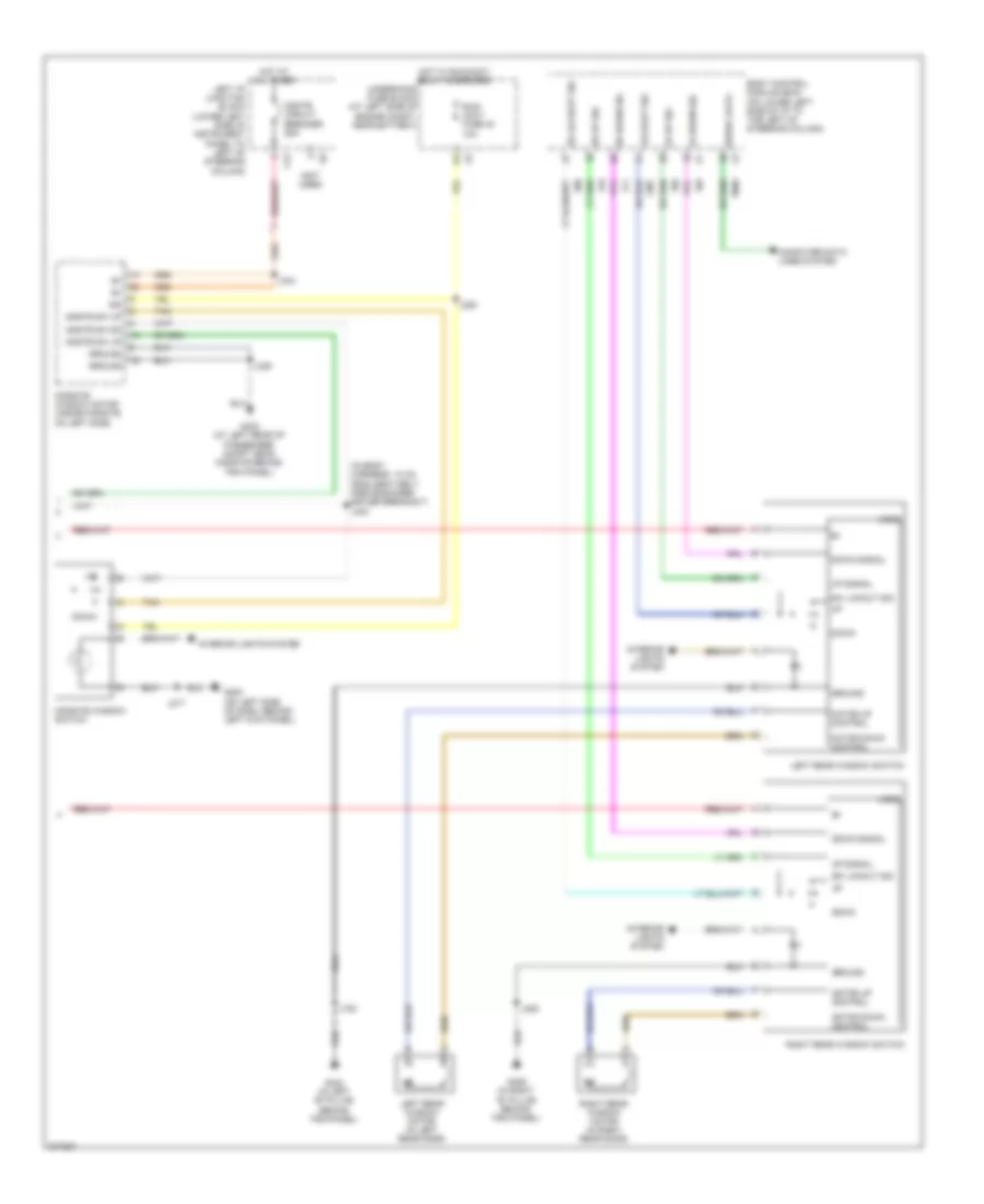 https://portal-diagnostov.com/license.html
Automotive Electricians Portal FZCO
Automotive Electricians Portal FZCO
https://portal-diagnostov.com/license.html
https://portal-diagnostov.com/license.html
Automotive Electricians Portal FZCO
Automotive Electricians Portal FZCOList of elements for Power Windows Wiring Diagram (2 of 2) for Hummer H2 2008:
- (in body harness, 10 cm from seat belt pretensioner- driver breakout) j340
- (not used)
- Body control module (bcm) (on lower left side of i/p to the left of steering column)
- Computer data lines system
- Down
- Down signal
- G200 (on left side of dash, behind left kick panel)
- G302 (in left "b" pillar behind trim panel)
- G306 (in right "b" pillar behind trim panel)
- G403 (at left rear of passenger compt near midgate behind trim panel)
- Ground
- Hot at all times
- Hot w/ run/accy relay energized
- Ign
- Interior lights system
- J217
- J220
- J334
- J339
- J720
- J820
- Left i/p junction block (lower left side of instrument panel to left of steering column)
- Left rear window motor (in left rear door)
- Left rear window switch
- Lockout sig
- Logic
- Lr down sig
- Lr up sig
- Mdgte sw dn
- Mdgte sw up
- Mgate circuit breaker 25a
- Midgate window motor (inside midgate on left side)
- Midgate window switch
- Motor down control
- Motor up control
- Right rear window motor (in right rear door)
- Right rear window switch
- Rr down sig
- Rr lockout sig
- Rr up sig
- Run/ accy fuse 40 10a
- Serial data
- Sw lckout sig
- Tan
- Underhood fuse block (at left side of engine compt, near battery)
- Up signal
- X12
RADIO
Radio Wiring Diagram, with Surround Amplifier (1 of 2) for Hummer H2 2008
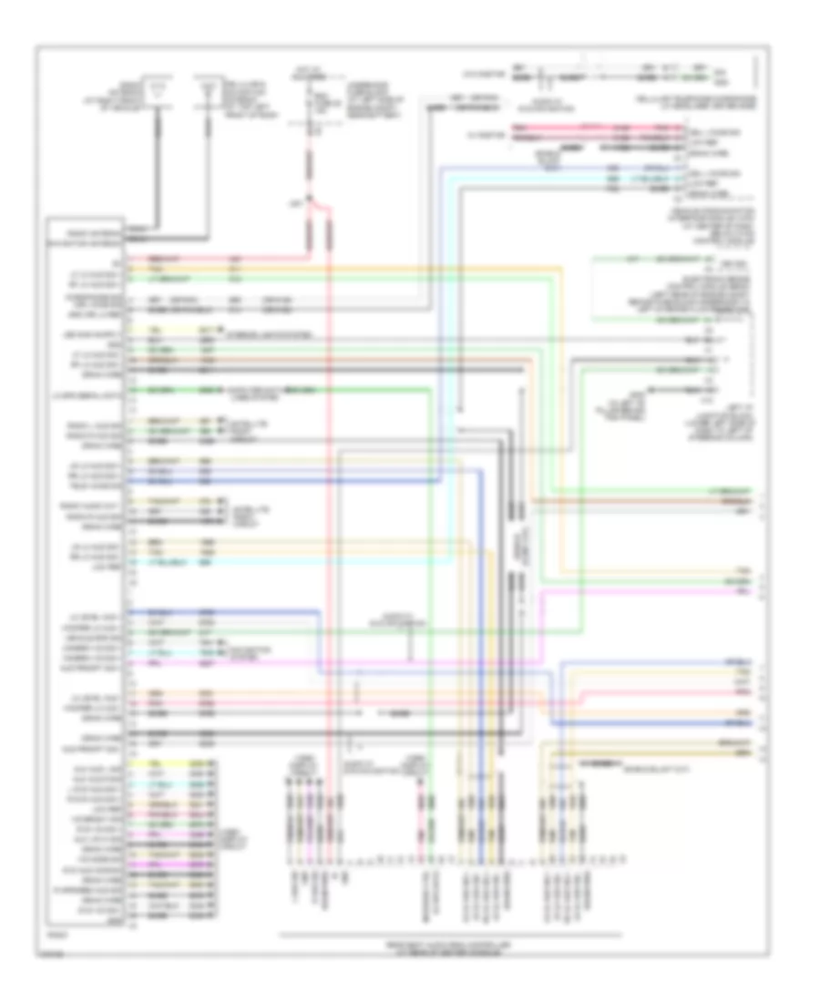 https://portal-diagnostov.com/license.html
Automotive Electricians Portal FZCO
Automotive Electricians Portal FZCO
https://portal-diagnostov.com/license.html
https://portal-diagnostov.com/license.html
Automotive Electricians Portal FZCO
Automotive Electricians Portal FZCOList of elements for Radio Wiring Diagram, with Surround Amplifier (1 of 2) for Hummer H2 2008:
- (lower left side of
- (or 5149)
- (or 5152)
- (or pnk)
- (or) voice sig
- Aud prompt sig +
- Aud prompt sig -
- Audio w/ dvd navigation
- Aux aud l sig
- Aux aud r sig
- Aux vid hi sig
- Bare
- Camera vid sig +
- Cell voice sig
- Cellular & navigation antenna (at top left front of roof)
- Cellular telephone microphone (lf headliner, driver side)
- Coax
- Computer data lines system
- Dash to left of steering column)
- Drain wire
- Dvd aud common
- Dvd vid sig +
- Dvd vid sig -
- Electronic brake control module (ebcm) (left rear of engine compt behind fuse block-underhood to left of brake fluid reservoir)
- G302 (in left "b" pillar behind trim panel)
- Gnd
- Gnd (or) lo ref
- Hot at all times
- Infrared ctrl
- Interior lights system
- J201
- L aud sig
- L dvd aud sig +
- Left i/p junction block
- Lf lo aud sig +
- Lf lo aud sig -
- Lo level aud +
- Lo level aud -
- Lo spd data
- Lo spd serial data
- Low ref
- Lr lo aud sig +
- Lr lo aud sig -
- Microphone sig
- Navigation antenna
- Navigation system
- Pnk
- R aud sig
- R dvd aud sig +
- R infrared aud sig
- Radio
- Radio antenna
- Radio antenna (at right front of vehicle)
- Radio audio out -
- Radio l aud sig
- Radio r aud sig
- Rdo fuse 36 15a
- Rear seat audio (rsa) controller (at rear of center console)
- Rf lo aud sig +
- Rf lo aud sig -
- Rr lo aud sig +
- Rr lo aud sig -
- Satellite radio circuit
- Sig
- Tan
- Tele voice sig
- Underhood fuse block (at left side of engine compt, near battery)
- Veh sig
- Vehicle communication interface module (vcim) (at center of dash, below hvac control module)
- Vehicle spd sig
- Vid bright sig
- Vid mode sig
- Video display circuit
- W/ onstar
- W/o onstar
- Woofer lo aud +
- Woofer lo aud -
- X12
Radio Wiring Diagram, with Surround Amplifier (2 of 2) for Hummer H2 2008
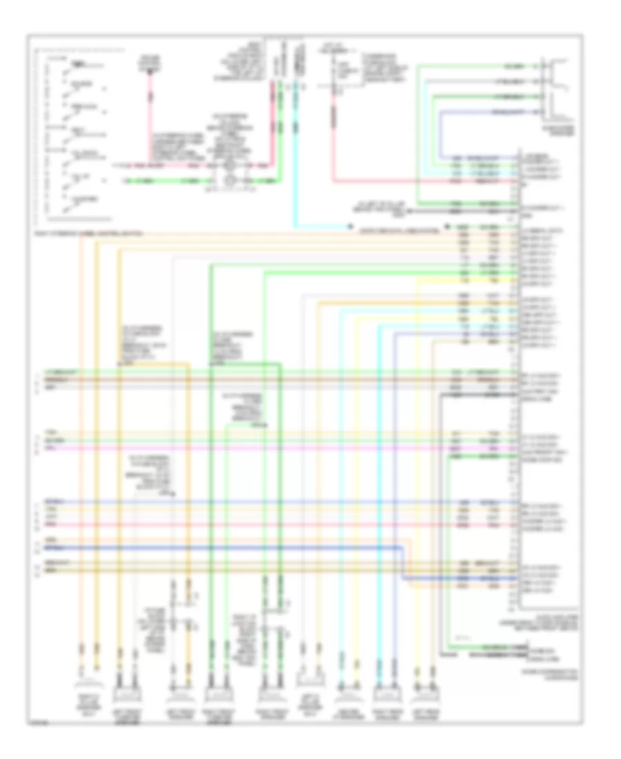 https://portal-diagnostov.com/license.html
Automotive Electricians Portal FZCO
Automotive Electricians Portal FZCO
https://portal-diagnostov.com/license.html
https://portal-diagnostov.com/license.html
Automotive Electricians Portal FZCO
Automotive Electricians Portal FZCOList of elements for Radio Wiring Diagram, with Surround Amplifier (2 of 2) for Hummer H2 2008:
- (in i/p harness in x298 breakout, 14 cm from breakout) j232
- (in i/p harness in x298 breakout, 9 cm from breakout) j233
- (in i/p harness, in fuse block- i/p x1 breakout, 24 cm from fuse block-i/p x1) j204
- (in i/p harness, in fuse block- i/p x1 breakout, 29 cm from fuse block i/p x1) j203
- (in left "b" pillar behind trim panel) g302
- (in steering wheel harness between right & left steering wheel control switches)
- (on steering column, behind steering wheel) inflatable restraint steering wheel module coil
- 12v ref
- 3a1
- 3a2
- A bare
- Amp fuse 35 30a
- Aud prmt sig -
- Aud prompt sig +
- Audio amplifier (under front floor console, between front seats)
- Bare
- Body control module (bcm) (on lower left side of i/p to the left of steering column)
- Cen lo aud +
- Cen lo aud -
- Cen spk out +
- Cen spk out -
- Center i/p speaker
- Computer data lines system
- Cruise control system
- Drain wire
- Gnd
- Hot at all times
- I/p fuse block (on lower left side of i/p, behind access panel)
- J235
- L or rear woofer out +
- L woofer out -
- Left d pillar speaker (suv)
- Left front speaker
- Left front tweeter speaker
- Left rear speaker
- Lf lo aud sig +
- Lf lo aud sig -
- Lf spk out +
- Lf spk out -
- Lo serial data
- Lr lo aud sig +
- Lr lo aud sig -
- Lr spk out +
- Lr spk out -
- Nca
- Nca noise sig nca drain wire
- Next
- Noise comp sig
- Noise compensation microphone
- Pnk
- R woofer out +
- R woofer out -
- Rf lo aud sig +
- Rf lo aud sig -
- Rf spk out +
- Rf spk out -
- Right d pillar speaker (suv)
- Right front speaker
- Right front tweeter speaker
- Right i/p junction block (right side of dash, behind end trim panel)
- Right rear speaker
- Right steering wheel control switch
- Rr lo aud sig +
- Rr lo aud sig -
- Rr spk out +
- Rr spk out -
- Seek
- Source
- Steering sig
- Subwoofer speaker
- Tan
- Tion enable communica-
- Underhood fuse block (at left side of engine compt, near battery)
- Voice rec
- Vol down
- Vol up
- Woofer lo aud +
- Woofer lo aud -
Radio Wiring Diagram, without Surround Amplifier (1 of 2) for Hummer H2 2008
 https://portal-diagnostov.com/license.html
Automotive Electricians Portal FZCO
Automotive Electricians Portal FZCO
https://portal-diagnostov.com/license.html
https://portal-diagnostov.com/license.html
Automotive Electricians Portal FZCO
Automotive Electricians Portal FZCOList of elements for Radio Wiring Diagram, without Surround Amplifier (1 of 2) for Hummer H2 2008:
- (or 5149)
- (or 5152)
- (or pnk)
- (or) voice sig
- Amplifier ctrl
- Audio w/ dvd navigation
- Aux aud l sig
- Aux aud r sig
- Aux vid hi sig
- Bare
- Camera vid sig +
- Cell voice sig
- Cellular & navigation antenna (at top left front of roof)
- Cellular telephone microphone (lf headliner, driver side)
- Coax
- Computer data lines system
- Drain wire
- Dvd aud common
- Dvd vid sig +
- Dvd vid sig -
- Electronic brake control module (ebcm) (left rear of engine compt behind fuse block-underhood to left of brake fluid reservoir)
- G302 (in left "b" pillar behind trim panel)
- Gnd
- Hot at all times
- Infrared ctrl
- Interior lights system
- J201
- L aud sig
- L dvd aud sig +
- Left i/p junction block (lower left side of dash to left of steering column)
- Lf lo aud sig +
- Lf lo aud sig -
- Lo ref (or) gnd
- Lo spd data
- Lo spd serial data
- Low ref
- Lr lo aud sig +
- Lr lo aud sig -
- Microphone sig
- Navigation antenna
- Navigation system
- Pnk
- R aud sig
- R dvd aud sig +
- R infrared aud sig
- Radio
- Radio antenna
- Radio antenna (at right front of vehicle)
- Radio audio out -
- Radio l aud sig
- Radio r aud sig
- Rdo fuse 36 15a
- Rear seat audio (rsa) controller (at rear of center console)
- Remote enable
- Rf lo aud sig +
- Rf lo aud sig -
- Rr lo aud sig +
- Rr lo aud sig -
- Satellite radio circuit
- Sig
- Tan
- Tele voice sig
- Underhood fuse block (at left side of engine compt, near battery)
- Vehicle communication interface module (vcim) (at center of dash, below hvac control module)
- Vehicle spd sig
- Vid bright sig
- Vid mode sig
- Video display circuit
- Vss
- W/ onstar
- W/o onstar
- X12
Radio Wiring Diagram, without Surround Amplifier (2 of 2) for Hummer H2 2008
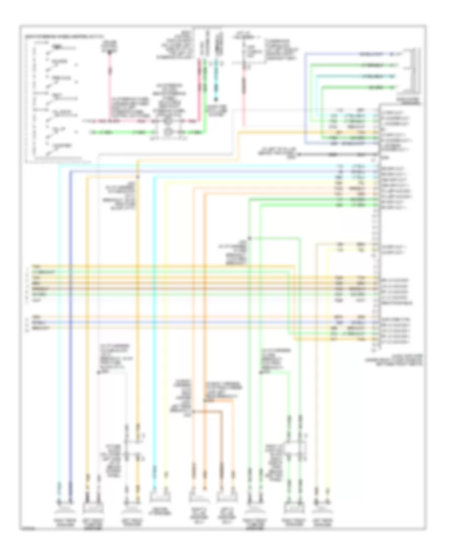 https://portal-diagnostov.com/license.html
Automotive Electricians Portal FZCO
Automotive Electricians Portal FZCO
https://portal-diagnostov.com/license.html
https://portal-diagnostov.com/license.html
Automotive Electricians Portal FZCO
Automotive Electricians Portal FZCOList of elements for Radio Wiring Diagram, without Surround Amplifier (2 of 2) for Hummer H2 2008:
- (in body harness 12 cm from marker lamp- left rear breakout) j332
- (in body harness, 15 cm from marker lamp-left rear breakout) j333
- (in i/p harness in x298 breakout, 14 cm from breakout)
- (in i/p harness in x298 breakout, 9 cm from breakout) j233
- (in i/p harness, in fuse block -i/p x1 breakout, 24 cm from fuse block-i/p x1) j204
- (in left "b" pillar behind trim panel) g302
- (in steering wheel harness between right & left steering wheel control switches)
- (on steering column, behind steering wheel) inflatable restraint steering wheel module coil
- 12v ref
- 3a1
- 3a2
- Amp fuse 35 30a
- Amplifier ctrl
- Audio amplifier (under front floor console, between front seats)
- Body control module (bcm) (on lower left side of i/p to the left of steering column)
- Cen spk out +
- Cen spk out -
- Center i/p speaker
- Communica- tion enable
- Computer data lines system
- Cruise control system
- Gnd
- Hot at all times
- I/p fuse block (on lower left side of i/p, behind access panel)
- J203 (in i/p harness, in fuse block -i/p x1 breakout, 29 cm from fuse block i/p x1)
- J232
- J235
- L or rear woofer out +
- L woofer out -
- Left d pillar speaker (suv)
- Left front speaker
- Left front tweeter speaker
- Left rear speaker
- Lf lo aud sig +
- Lf lo aud sig -
- Lf spk out +
- Lf spk out -
- Lr lo aud sig +
- Lr lo aud sig -
- Lr spk out +
- Lr spk out -
- Nca
- Next
- Piller aud sig +
- Piller aud sig -
- Pnk
- R woofer out +
- R woofer out -
- Remote enable
- Rf lo aud sig +
- Rf lo aud sig -
- Rf spk out +
- Rf spk out -
- Right d pillar speaker (suv)
- Right front speaker
- Right front tweeter speaker
- Right i/p junction block (right side of dash, behind end trim panel)
- Right rear speaker
- Right steering wheel control switch
- Rr lo aud sig +
- Rr lo aud sig -
- Rr spk out +
- Rr spk out -
- Seek
- Source
- Steering sig
- Subwoofer speaker
- Tan
- Underhood fuse block (at left side of engine compt, near battery)
- Voice rec
- Vol down
- Vol up
Satellite Radio Wiring Diagram for Hummer H2 2008
 https://portal-diagnostov.com/license.html
Automotive Electricians Portal FZCO
Automotive Electricians Portal FZCO
https://portal-diagnostov.com/license.html
https://portal-diagnostov.com/license.html
Automotive Electricians Portal FZCO
Automotive Electricians Portal FZCOList of elements for Satellite Radio Wiring Diagram for Hummer H2 2008:
- (lower left side of dash to left of steering column) left i/p junction block
- Aud out -
- Bare
- Cellular, navigation & digital radio antenna (at top left front of roof)
- Coax
- Computer data lines system
- Digital radio receiver (behind glove box)
- Drain wire
- G302 (in left "b" pillar behind trim panel)
- Gnd
- Hot at all times
- J204
- L aud sig
- Lo spd data
- Lt aud sig+
- Navi antenna
- R aud sig
- Radio
- Rdo fuse 36 15a
- Rt aud sig+
- Underhood fuse block (at left side of engine compt, near battery)
- X12
Video Display Wiring Diagram for Hummer H2 2008
 https://portal-diagnostov.com/license.html
Automotive Electricians Portal FZCO
Automotive Electricians Portal FZCO
https://portal-diagnostov.com/license.html
https://portal-diagnostov.com/license.html
Automotive Electricians Portal FZCO
Automotive Electricians Portal FZCOList of elements for Video Display Wiring Diagram for Hummer H2 2008:
- Audio amplifier (under front floor console, between front seats)
- Audio video adapter (rear of center console below rear seat audio control)
- Auxiliary aud l sig
- Auxiliary aud r sig
- Auxiliary vid hi sig
- Bare
- Computer data lines system
- Drain wire
- Dvd aud common
- Dvd vid sig +
- Dvd vid sig -
- G302 (in left "b" pillar behind trim panel)
- Gnd
- Hot at all times
- Info fuse 5a
- Infrared ctrl
- Infrared module ctrl
- Infrared transmitter (in roof-mounted dvd system)
- J206
- L aud sig
- L dvd aud sig +
- L infrared aud sig
- Left i/p junction block (lower left side of instrument panel to left of steering column)
- Lo spd serial data
- Low ref
- Nca
- Pnk
- R aud sig
- R dvd aud sig +
- R infrared aud sig
- Radio
- Rear seat audio (rsa) controller (at rear of center console)
- Remote enable
- Underhood fuse block (at left side of engine compt, near battery)
- Vid bright sig
- Vid mode sig
- Video display (in headliner between front & second row seating)
- Video mode sig
- X12
SHIFT INTERLOCK
Ignition Lock Solenoid Wiring Diagram for Hummer H2 2008
 https://portal-diagnostov.com/license.html
Automotive Electricians Portal FZCO
Automotive Electricians Portal FZCO
https://portal-diagnostov.com/license.html
https://portal-diagnostov.com/license.html
Automotive Electricians Portal FZCO
Automotive Electricians Portal FZCOList of elements for Ignition Lock Solenoid Wiring Diagram for Hummer H2 2008:
- Automatic transmission shift lever
- G203 (at lower right side of dash, behind right kick panel)
- Hot w/ run/accy pcb relay energized
- Ignition lock cylinder control solenoid (in upper steering column on ignition key cylinder)
- J218
- J220
- Park switch
- Run/accy fuse 40 10a
- Underhood fuse block (at left side of engine compt, near battery)
Shift Interlock Wiring Diagram for Hummer H2 2008
 https://portal-diagnostov.com/license.html
Automotive Electricians Portal FZCO
Automotive Electricians Portal FZCO
https://portal-diagnostov.com/license.html
https://portal-diagnostov.com/license.html
Automotive Electricians Portal FZCO
Automotive Electricians Portal FZCOList of elements for Shift Interlock Wiring Diagram for Hummer H2 2008:
- A/t shift lck ctrl x2
- Automatic transmission shift lever
- Automatic transmission shift lever control solenoid
- Bcm fuse 10a
- Body control module (bcm) (on lower left side of i/p to the left of steering column)
- E (not used)
- Exterior lights system
- G203 (at lower right side of dash, behind right kick panel)
- Hot at all times
- Hot w/ run/crank relay energized
- J351
- Left i/p junction block (lower left side of instrument x1 panel to left of steering column)
- Misc ign fuse 37 10a
- Pnk
- Shift lock relay
- Stop lamp switch (on top of brake pedal bracket)
- Tcc brake sig x5
- Underhood fuse block (at left side of engine compt, near battery)
STARTING/CHARGING
Charging Wiring Diagram for Hummer H2 2008
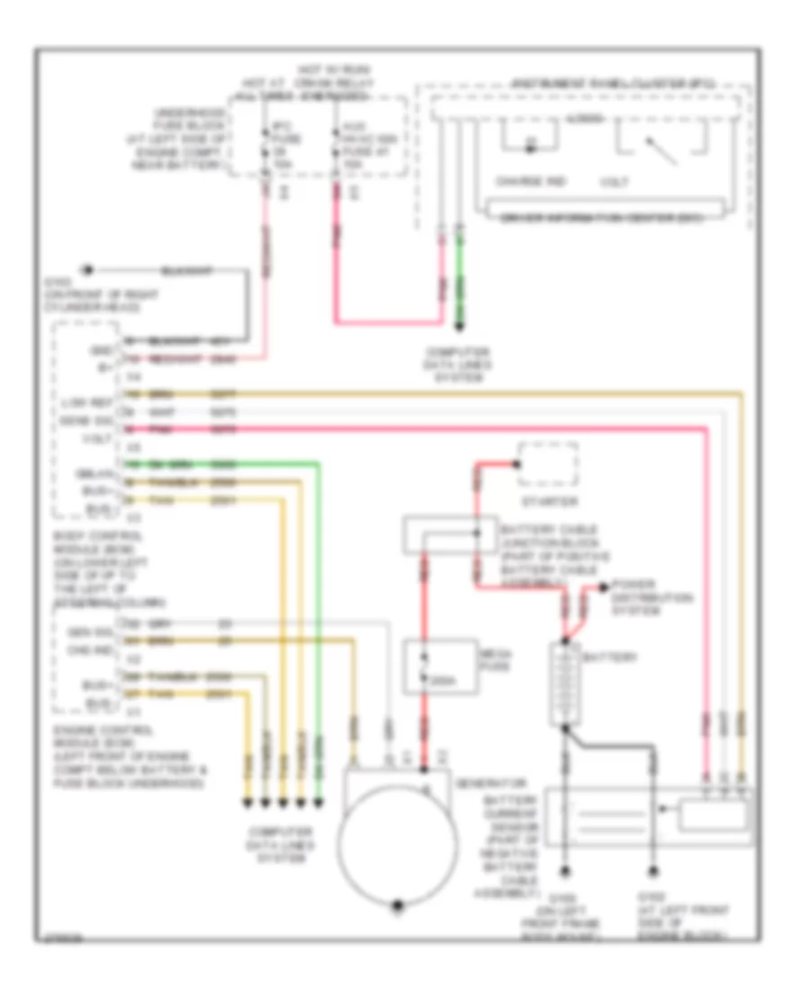 https://portal-diagnostov.com/license.html
Automotive Electricians Portal FZCO
Automotive Electricians Portal FZCO
https://portal-diagnostov.com/license.html
https://portal-diagnostov.com/license.html
Automotive Electricians Portal FZCO
Automotive Electricians Portal FZCOList of elements for Charging Wiring Diagram for Hummer H2 2008:
- 200a
- Aux hvac ign fuse 41 10a
- Battery
- Battery cable junction block (part of positive battery cable assembly)
- Body control module (bcm) (on lower left side of i/p to the left of steering column)
- Bus+
- Bus-
- Charge ind
- Chg ind
- Computer data lines system
- Driver information center (dic)
- Engine control module (ecm) (left front of engine compt below battery & fuse block underhood)
- G100 (on left front frame body mount)
- G102 (at left front side of engine block)
- G103 (on front of right cylinder head)
- Gen sig
- Generator
- Gmlan
- Gnd
- Hot at all times
- Hot w/ run/ crank relay energized
- Instrument panel cluster (ipc)
- Ipc fuse 10a
- Logic
- Low ref
- Mega fuse
- Pnk
- Power distribution system
- Red
- Sens sig
- Starter
- Tan
- Underhood fuse block (at left side of engine compt, near battery)
- Volt
Starting Wiring Diagram for Hummer H2 2008
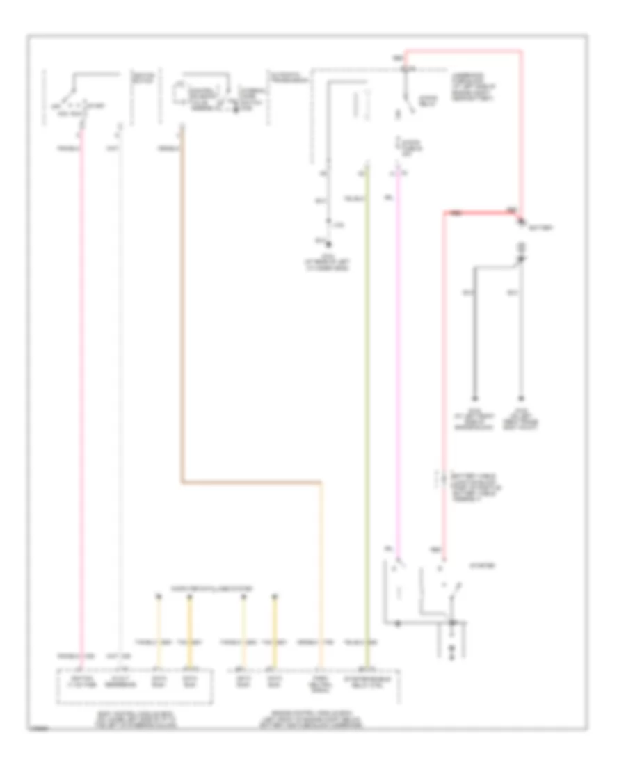 https://portal-diagnostov.com/license.html
Automotive Electricians Portal FZCO
Automotive Electricians Portal FZCO
https://portal-diagnostov.com/license.html
https://portal-diagnostov.com/license.html
Automotive Electricians Portal FZCO
Automotive Electricians Portal FZCOList of elements for Starting Wiring Diagram for Hummer H2 2008:
- 5-volt reference
- Automatic transmission
- Battery
- Battery cable junction block (part of positive battery cable assembly)
- Body control module (bcm) (on lower left side of i/p to the left of steering column)
- Computer data lines system
- Control solenoid valve assembly
- Data bus+
- Data bus-
- Engine control module (ecm) (left front of engine compt below battery and fuse block underhood)
- G100 (on left front frame body mount)
- G102 (at left front side of engine block)
- G104 (at rear of left cylinder head)
- Ignition iii voltage
- Ignition switch
- Internal mode switch (ims)
- J102
- Off
- P/n
- Park/ neutral signal
- Red
- Run acc
- Start
- Starter
- Starter enable relay ctrl
- Strtr fuse 54 40a
- Strtr relay
- Tan
- Underhood fuse block (at left side of engine compt, near battery)
- X2 f1
SUPPLEMENTAL RESTRAINTS
Supplemental Restraints Wiring Diagram (1 of 2) for Hummer H2 2008
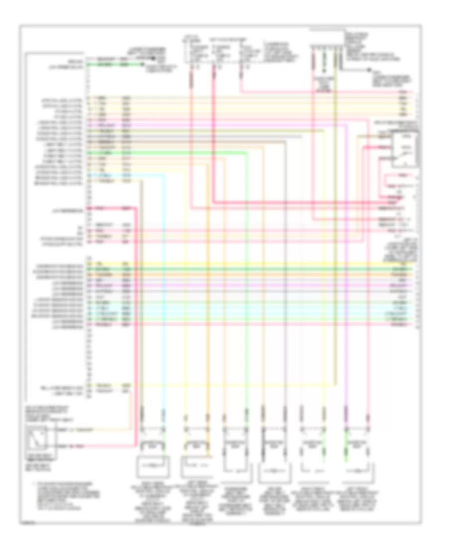 https://portal-diagnostov.com/license.html
Automotive Electricians Portal FZCO
Automotive Electricians Portal FZCO
https://portal-diagnostov.com/license.html
https://portal-diagnostov.com/license.html
Automotive Electricians Portal FZCO
Automotive Electricians Portal FZCOList of elements for Supplemental Restraints Wiring Diagram (1 of 2) for Hummer H2 2008:
- (under passenger seat toward right side near x305) g301
- Air bag batt fuse 38 15a
- Air bag ign fuse 34 10a
- Aux- hvac-ign fuse 41 10a
- Computer data lines system
- Discriminating sens sig
- Driver seat belt buckle
- Driver seat belt pretensioner (part of driver seat belt retractor assembly)
- Driver seat belt switch
- G301 (under passenger seat toward right side near x305)
- Ground
- Hot at all times
- Hot in on or start
- I/p mod disable sw sig
- I/p mod hi ctrl
- I/p mod lo ctrl
- I/p mod supp ind ctrl
- Ign
- Inflatable restraint i/p module disable switch
- Inflatable restraint sensing & diagnostic module (sdm) (under left front seat)
- Inflatable restraint vehicle rollover sensor (below center console in front of audio amplifier)
- L impact sensing mod sig
- L roof rail mod hi ctrl
- L roof rail mod lo ctrl
- L seat belt hi ctrl
- L seat belt lo ctrl
- L seat belt sw
- Left front inflatable restraint roof rail module (behind left side of headliner trim to rear of c-pillar)
- Left i/p junction block (lower left side of instrument panel to left of steering column)
- Left rear inflatable restraint roof rail module (w/ suburban/ utility rear seat) (behind left side of headliner trim above quarter window)
- Low reference
- Low speed gmlan
- Lr impact sensing mod sig
- Lr roof rail mod hi ctrl
- Lr roof rail mod lo ctrl
- Nca
- Passenger seat belt pretensioner (part of passenger seat belt retractor assembly)
- Pin shorting bars engaged when module connector is disconnected from harness (shorting bars are connected between pins: 8-9,10-11,12-13,14-15, 16-17,18-19,20-21 & 22-23)
- Pnk
- Pnk a
- Pnk b
- R discriminating sens sig
- R impact sensing mod sig
- R roof rail mod hi ctrl
- R roof rail mod lo ctrl
- R seat belt hi ctrl
- R seat belt lo ctrl
- Right front inflatable restraint roof rail module (behind right side of headliner trim to rear of c-pillar)
- Right rear inflatable restraint roof rail module (w/ suburban/ utility rear seat) (behind right side of headliner trim above quarter window)
- Roll over sens hi sig
- Rr impact sensing mod sig
- Rr roof rail mod hi ctrl
- Rr roof rail mod lo ctrl
- Shorting bar
- Str whl mod hi ctrl
- Str whl mod lo ctrl
- Tan
- Underhood fuse block (at left side of engine compt, near battery)
- X11
Supplemental Restraints Wiring Diagram (2 of 2) for Hummer H2 2008
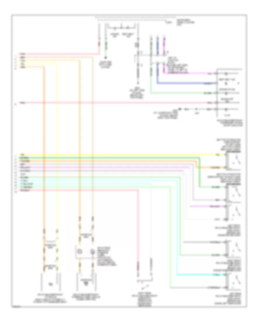 https://portal-diagnostov.com/license.html
Automotive Electricians Portal FZCO
Automotive Electricians Portal FZCO
https://portal-diagnostov.com/license.html
https://portal-diagnostov.com/license.html
Automotive Electricians Portal FZCO
Automotive Electricians Portal FZCOList of elements for Supplemental Restraints Wiring Diagram (2 of 2) for Hummer H2 2008:
- (bottom of radiator core support on left side) left inflatable restraint front end sensor
- (bottom of radiator core support on right side) right inflatable restraint front end sensor
- Air bag ind
- Air bag off ind
- Air bag on ind
- Computer data lines system
- G200 (on left side of dash, behind left kick panel)
- G203 (at lower right side of dash, behind right kick panel)
- Illum
- Inflatable restraint i/p module (right side of i/p directly in front of passenger seat)
- Inflatable restraint passenger air bag on/off indicator
- Inflatable restraint steering wheel module (under horn pad)
- Inflatable restraint steering wheel module coil (on steering column, behind steering wheel)
- Instrument panel cluster (ipc)
- J321
- Left front inflatable restraint side impact sensor (sis) (inside driver door)
- Left i/p junction block (lower left side of instrument panel to left of steering column)
- Left rear inflatable restraint side impact sensor (sis) (inside left rear door)
- Logic
- Pnk
- Right front inflatable restraint side impact sensor (sis) (inside passenger door)
- Right rear inflatable restraint side impact sensor (sis) (inside right rear door)
- Seat belt ind
- Shorting bar
- Tan
TRANSMISSION
A/T Wiring Diagram (1 of 2) for Hummer H2 2008
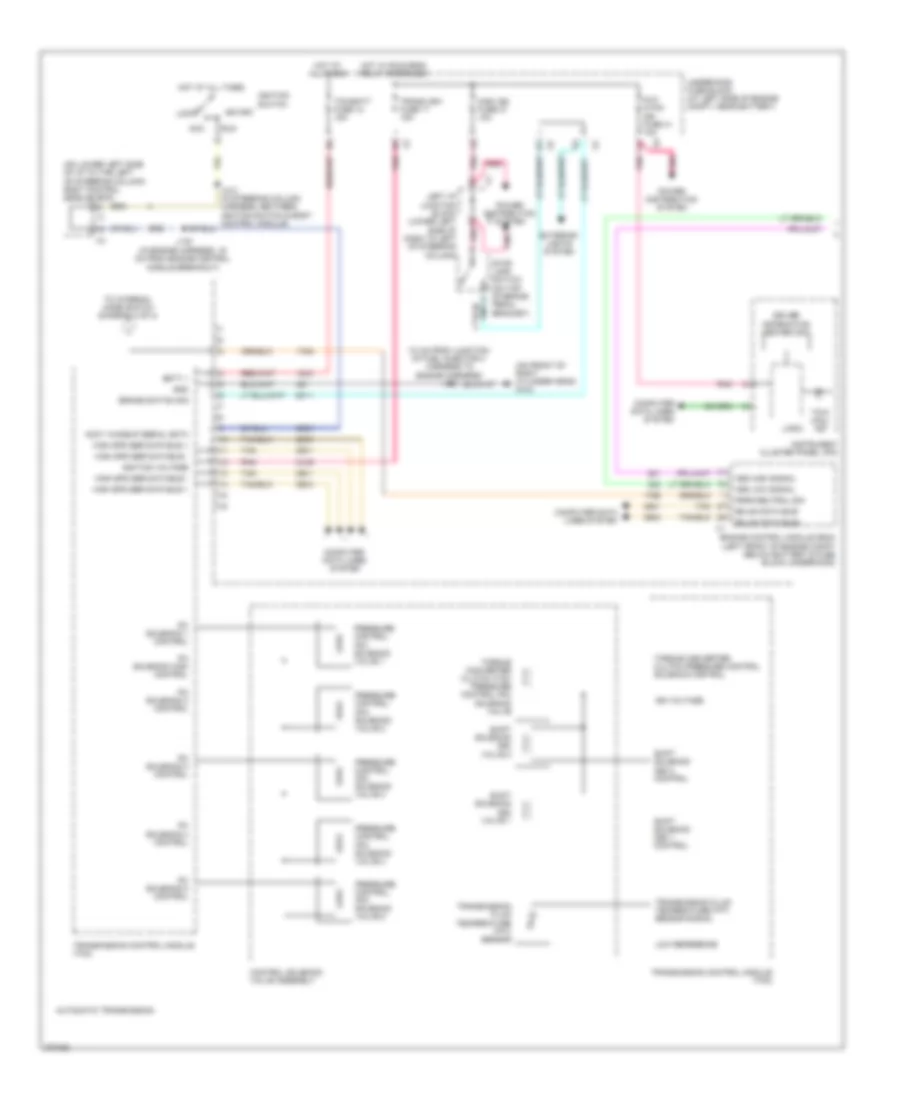 https://portal-diagnostov.com/license.html
Automotive Electricians Portal FZCO
Automotive Electricians Portal FZCO
https://portal-diagnostov.com/license.html
https://portal-diagnostov.com/license.html
Automotive Electricians Portal FZCO
Automotive Electricians Portal FZCOList of elements for A/T Wiring Diagram (1 of 2) for Hummer H2 2008:
- (10 cm from junction of fuel injector 3 harness to engine harness) j103
- (on front of right cylinder head) g103
- (on lower left side of i/p to the left of steering column) body control module (bcm)
- Acc
- Accy wakeup serial data
- Automatic transmission
- Aux hvac- ign fuse 41 10a
- Batt +
- Brake switch sig
- Computer data lines system
- Control solenoid valve assembly
- Driver information center (dic)
- Engine control module (ecm) (left front of engine compt below battery & fuse block underhood)
- Exterior lights system
- Gmlan data bus+
- Gmlan data bus-
- Gnd
- High spd ser data bus +
- High spd ser data bus -
- Hot at all times
- Hot w/ run/crnk relay energized
- Ign voltage
- Ignition switch
- Ignition voltage
- Instrument cluster panel (ipc)
- J130 (in engine harness, 16 cm from engine control module breakout)
- J213 (in steering column harness, between ignition switch & body control module)
- Left i/p junction block (lower left side of dash to left of steering column)
- Lock
- Logic
- Low reference
- Misc ign fuse 37 10a
- Park/neutral sig
- Pc solenoid 1 control
- Pc solenoid 2 control
- Pc solenoid 3 control
- Pc solenoid 4 control
- Pc solenoid 5 control
- Pc solenoid high control
- Pnk
- Power distribution system
- Pressure control (pc) solenoid valve 1
- Pressure control (pc) solenoid valve 2
- Pressure control (pc) solenoid valve 3
- Pressure control (pc) solenoid valve 4
- Pressure control (pc) solenoid valve 5
- Run
- Shift solenoid (ss) 1 control
- Shift solenoid (ss) 2 control
- Shift solenoid (ss) valve 1
- Shift solenoid (ss) valve 2
- Start
- Stop lamp switch (on top of brake pedal bracket)
- Tan
- Tcm-batt fuse 12 15a
- To internal mode switch (diagram 2 of 2)
- Torque converter clutch (tcc) pressure control (pc) solenoid valve
- Torque converter clutch pressure control solenoid control
- Tow/ haul ind
- Trans ign1 fuse 17 15a
- Transmission control module (tcm)
- Transmission fluid temperature (tft) sensor
- Transmission fluid temperature (tft) sensor signal
- Underhood fuse block (at left side of engine compt, near battery)
- Vss high signal
- Vss low signal
A/T Wiring Diagram (2 of 2) for Hummer H2 2008
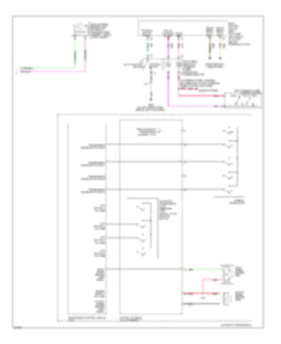 https://portal-diagnostov.com/license.html
Automotive Electricians Portal FZCO
Automotive Electricians Portal FZCO
https://portal-diagnostov.com/license.html
https://portal-diagnostov.com/license.html
Automotive Electricians Portal FZCO
Automotive Electricians Portal FZCOList of elements for A/T Wiring Diagram (2 of 2) for Hummer H2 2008:
- (diagram 1 of 2)
- (in steering wheel harness between right & left steering wheel control switches) j235
- 12-vol ref
- Automatic transmission
- Automatic transmission fluid pressure (tfp) manual valve position switch
- Body control module (bcm) (on lower left side of i/p to the left of steering column)
- Computer data lines system
- Control solenoid valve assembly
- From automatic transmission a
- Ftp switch 1 voltage
- Ftp switch 3 voltage
- Ftp switch 4 voltage
- Ftp switch 5 voltage
- G200 (on left side of dash, behind left kick panel)
- Gmlan serial data bus +
- Gmlan serial data bus -
- I/p multi-function switch
- Inflatable restraint steering wheel module coil x2 (under horn pad)
- Input speed sensor (iss)
- Input speed sensor (oss) signal
- Internal mode switch
- J127
- J217
- Left steering wheel control switch
- Output speed sensor (oss)
- Output speed sensor (oss) signal
- P/n
- Pnk
- Red
- Sound systems
- Tan
- Tap up/ tap down sw sig
- Tow/haul switch
- Tow/haul switch signal
- Transmission control module (tcm)
- Transmission range switch sig a
- Transmission range switch sig b
- Transmission range switch sig c
- Transmission range switch sig p
- Vehicle speed sensor (vss) (on rear of transfer case assembly above output shaft)
Transfer Case Wiring Diagram for Hummer H2 2008
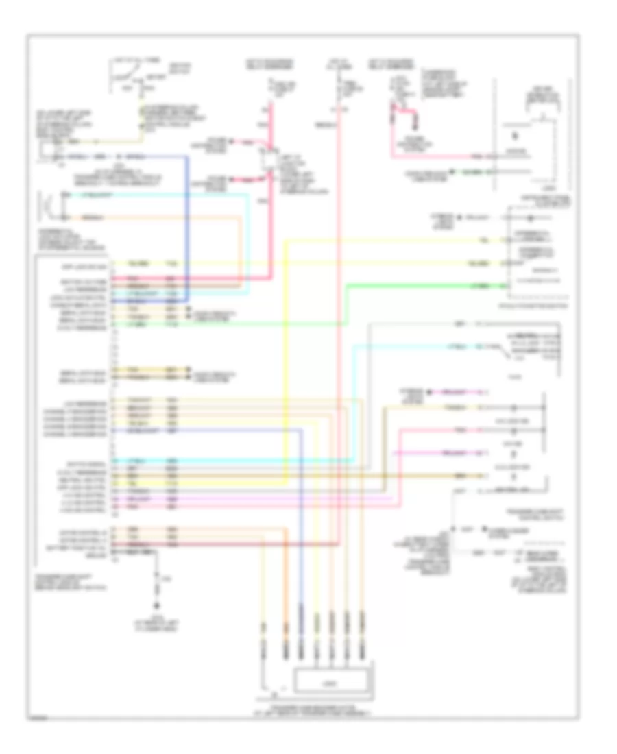 https://portal-diagnostov.com/license.html
Automotive Electricians Portal FZCO
Automotive Electricians Portal FZCO
https://portal-diagnostov.com/license.html
https://portal-diagnostov.com/license.html
Automotive Electricians Portal FZCO
Automotive Electricians Portal FZCOList of elements for Transfer Case Wiring Diagram for Hummer H2 2008:
- (on lower left side of i/p to the left of steering column) body control module (bcm)
- 4 hi
- 4 hi ind control
- 4 hi lock
- 4 lo ind control
- 4 lo lock
- 4 wd ind control
- 4-hi ind
- 4-hi lock ind
- 4-lo lock ind
- 4wd ind
- 5-volt reference
- Acc
- Aux hvac- ign fuse 41 10a
- Battery positive vol
- Body control module (bcm) (on lower left side of i/p to the left of steering column)
- Channel a encoder sig
- Channel b encoder sig
- Channel c encoder sig
- Channel p encoder sig
- Computer data lines system
- Diff lock ind ctrl
- Diff lock sw sig
- Differential lock actuator (on rear axle at top of differential housing)
- Differential lock ind
- Differential lock switch
- Driver information center (dic)
- G104 (at rear of left cylinder head)
- Ground
- Hot at all times
- Hot w/ run/crank relay energized
- Hot w/ run/crnk relay energized
- I/p multi-function switch
- Ignition switch
- Ignition voltage
- Instrument panel cluster (ipc)
- Interior lights system
- J102
- J231 (w/ rear window intermittent wiper) (in i/p harness, 5 cm from transfer case control module breakout)
- J234 (in i/p harness, in transfer case control module breakout, 7 cm from breakout)
- Left i/p junction block (lower left side of dash to left of steering column)
- Lock
- Lock actuator ctrl
- Logic
- Low reference
- Misc ign fuse 37 10a
- Motor control a
- Motor control b
- Nca
- Neutral
- Neutral ind
- Neutral ind ctrl
- Pnk
- Power distribution system
- Rear wiper/ washer sw x5
- Run
- Serial data bus+
- Serial data bus-
- Start
- Switch signal
- Tan
- Transfer case encoder motor (at left rear of transfer case assembly)
- Transfer case shift control module (behind headlight switch)
- Transfer case shift control switch
- Trec fuse 58 30a
- Underhood fuse block (at left side of engine compt, near battery)
- Wakeup serial data
- Wiper/washer system
- X5 f1
TRUNK, TAILGATE, FUEL DOOR
Midgate Wiring Diagram for Hummer H2 2008
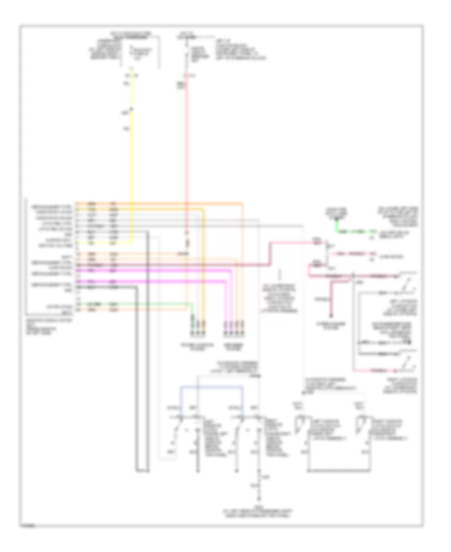 https://portal-diagnostov.com/license.html
Automotive Electricians Portal FZCO
Automotive Electricians Portal FZCO
https://portal-diagnostov.com/license.html
https://portal-diagnostov.com/license.html
Automotive Electricians Portal FZCO
Automotive Electricians Portal FZCOList of elements for Midgate Wiring Diagram for Hummer H2 2008:
- (at lower right side of liftgate, 6.5 cm from right liftgate ajar switch junction to liftgate harness)
- (in midgate harness 13 cm from midgate latch -- left breakout) j335
- (in midgate harness, 13 cm from left midgate latch breakout) j336
- (inside right side of midgate behind midgate trim panel)
- (on lower left side of i/p to the left of steering column) body control module (bcm)
- (on passenger side rear of body near d-pillar behind trim panel) g410
- Ajar ind sig
- Ajar sw sig 1
- Batt
- Computer data lines system
- D4 x5
- Defog element ctrl
- Defogger system
- G403 (at left rear of passenger compt near midgate behind trim panel)
- Gnd
- Hot at all times
- Hot w/ run/accy pcb relay energized
- Ignition voltage
- J220
- J334
- J339
- J901
- J902
- Latch rel ctrl
- Latch rel sw sig
- Left i/p junction block (lower left side of instrument panel to left of steering column)
- Left liftgate ajar switch (at lower left side of liftgate)
- Left midgate latch (inside left side of midgate behind midgate trim panel)
- Left midgate latch switch (in midgate near left latch assembly)
- Low spd gmlan serial data
- Mgate circuit breaker 25a
- Midgate sw dn sig
- Midgate sw up sig
- Midgate window motor (sut) (inside midgate on left side)
- Motor up sig
- Power windows system
- Right liftgate ajar switch (at lower right side of liftgate)
- Right midgate latch
- Right midgate latch switch (in midgate near right latch assembly)
- Run/accy fuse 40 10a
- Sut
- Suv
- Tan
- Underhood fuse block (at left side of engine compt, near battery)
- Wiper/washer system
- X12
WARNING SYSTEMS
Warning Systems Wiring Diagram for Hummer H2 2008
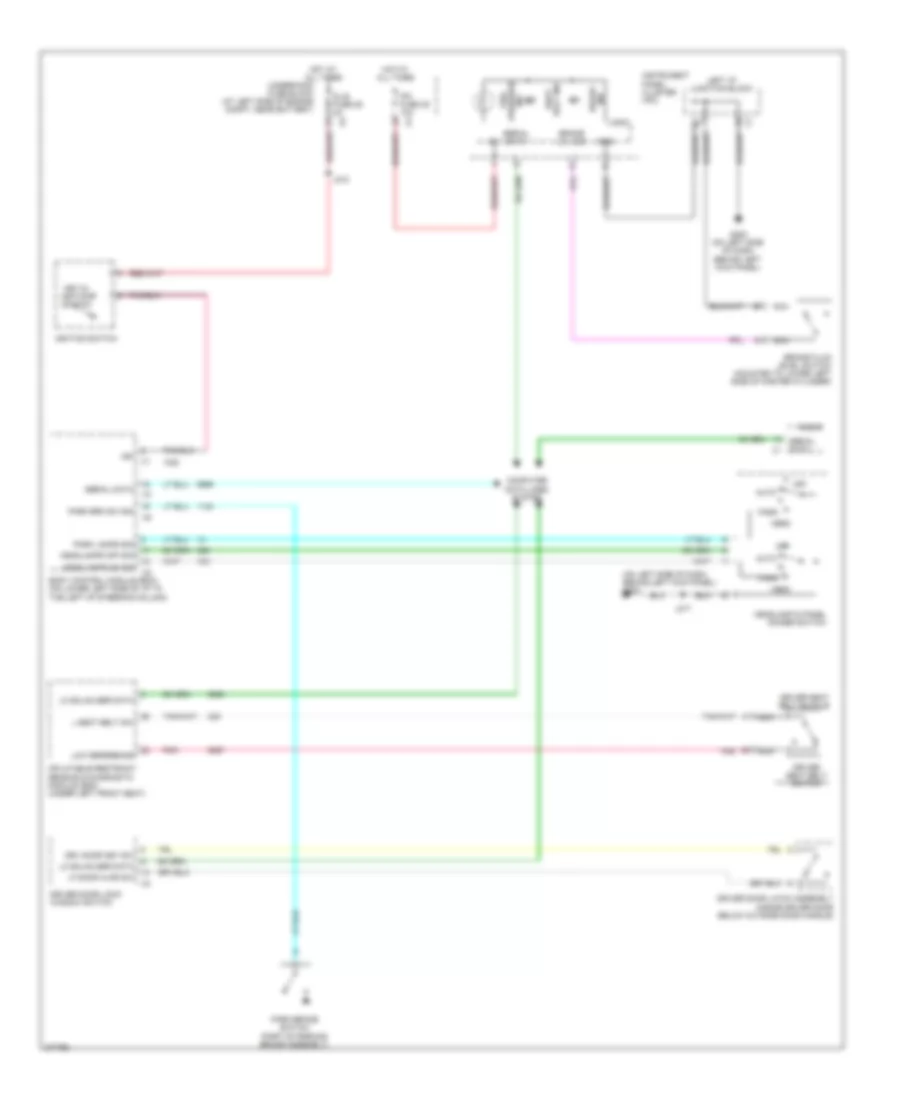 https://portal-diagnostov.com/license.html
Automotive Electricians Portal FZCO
Automotive Electricians Portal FZCO
https://portal-diagnostov.com/license.html
https://portal-diagnostov.com/license.html
Automotive Electricians Portal FZCO
Automotive Electricians Portal FZCOList of elements for Warning Systems Wiring Diagram for Hummer H2 2008:
- (on left side of dash, behind left kick panel) g200
- Auto
- Body control module (bcm) (on lower left side of i/p to the left of steering column)
- Brake fluid level switch (mounted to lower left side of master cylinder)
- Brake lvl sig
- Computer data lines system
- Dlis fuse 29 2a
- Driver door latch assembly (inside driver door below outside door handle)
- Driver door lock/ window switch
- Driver seat belt buckle
- Driver seat belt switch
- Drv door key sw
- G200 (on left side of dash, behind left kick panel)
- Gnd
- Head
- Headlamp & panel dimmer switch
- Headlamps off sig
- Headlamps on sig
- Hot at all times
- Ign
- Ignition switch
- Ind brake
- Inflatable restraint sensing & diagnostic module (sdm) (under left front seat)
- Instrument panel cluster (ipc)
- Ipc fuse 39 10a
- J212
- J217
- Key-in ignition switch
- L seat belt sw
- Left i/p junction block
- Lf door ajar sw
- Lo gmlan ser data
- Logic
- Low reference
- Nca
- Off
- Park
- Park brake switch (part of parking brake assembly)
- Park brk sw sig
- Park lamps sig
- Pnk
- Radio
- Seat belt ind
- Serial data
- Serial data x1
- Tire pressure ind
- Underhood fuse block (at left side of engine compt, near battery)
WIPER/WASHER
Front Wiper/Washer Wiring Diagram for Hummer H2 2008
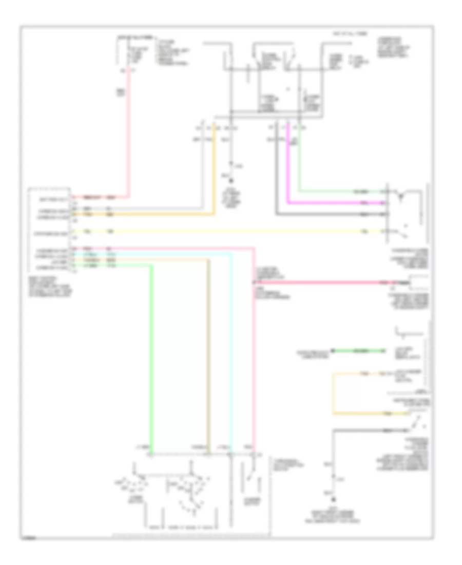 https://portal-diagnostov.com/license.html
Automotive Electricians Portal FZCO
Automotive Electricians Portal FZCO
https://portal-diagnostov.com/license.html
https://portal-diagnostov.com/license.html
Automotive Electricians Portal FZCO
Automotive Electricians Portal FZCOList of elements for Front Wiper/Washer Wiring Diagram for Hummer H2 2008:
- Bat pos volt
- Body control module (bcm) (on lower left side of dash, to left side of steering column)
- Computer data lines system
- G101 (right front corner of vehicle on frame rail near front tow hook)
- G104 (at rear of left cylinder head)
- Hot at all times
- I/p fuse block (on lower left side of i/p, behind access panel)
- Instrument panel cluster (ipc)
- Int
- J101
- J102
- J296 (in steering column harness)
- K1 x5
- Logic
- Low ref
- Low spd gmlan serial data
- Low washer fluid ind ctrl
- Mist
- Mtr park sw sig
- N5 x2
- Nca
- Off
- Pnk
- Rt stop turn fuse 15a
- Tan
- Turn signal/ multi-function switch
- Underhood fuse block (at left side of engine compt, near battery)
- W/ heated windshield washer fluid
- Washer sw sig
- Washer switch
- Windshield washer fluid level switch (left front corner of engine compt mounted in bottom of windshield washer fluid reservoir)
- Windshield washer solvent heater (left rear corner of engine compt)
- Windshield wiper motor (under windshield cowl between wiper arms)
- Wiper control pcb relay
- Wiper high speed diode
- Wiper low speed diode
- Wiper speed pcb relay
- Wiper sw hi sig
- Wiper sw lo sig
- Wiper sw sig 2
- Wiper switch
- Wpr fuse 30 25a
Heated Windshield Washer Wiring Diagram for Hummer H2 2008
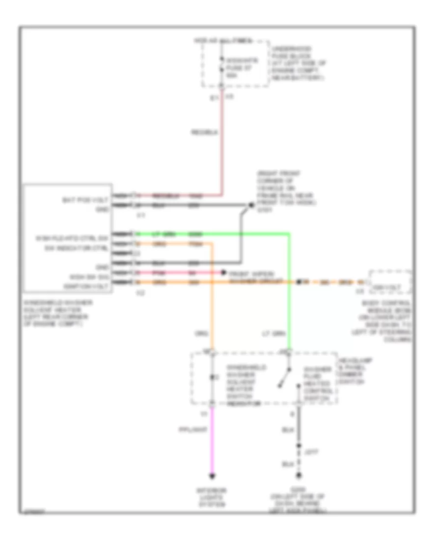 https://portal-diagnostov.com/license.html
Automotive Electricians Portal FZCO
Automotive Electricians Portal FZCO
https://portal-diagnostov.com/license.html
https://portal-diagnostov.com/license.html
Automotive Electricians Portal FZCO
Automotive Electricians Portal FZCOList of elements for Heated Windshield Washer Wiring Diagram for Hummer H2 2008:
- (right front corner of vehicle on frame rail near front tow hook) g101
- Body control module (bcm) (on lower left side dash, to left of steering column)
- Front wiper/ washer circuit
- G200 (on left side of dash, behind left kick panel)
- Headlamp & panel dimmer switch
- Hot at all times
- Ign volt
- Interior lights system
- J217
- J230
- Nca
- Nca bat pos volt
- Nca gnd
- Nca ignition volt
- Nca sw indicator ctrl
- Nca wsh fld htd ctrl sw
- Nca wsh sw sig
- Pnk
- Underhood fuse block (at left side of engine compt, near battery)
- Washer fluid heated control switch
- Windshield washer solvent heater (left rear corner of engine compt)
- Windshield washer solvent heater switch indicator
- Wsw/htr fuse 57 60a
Rear Wiper/Washer Wiring Diagram for Hummer H2 2008
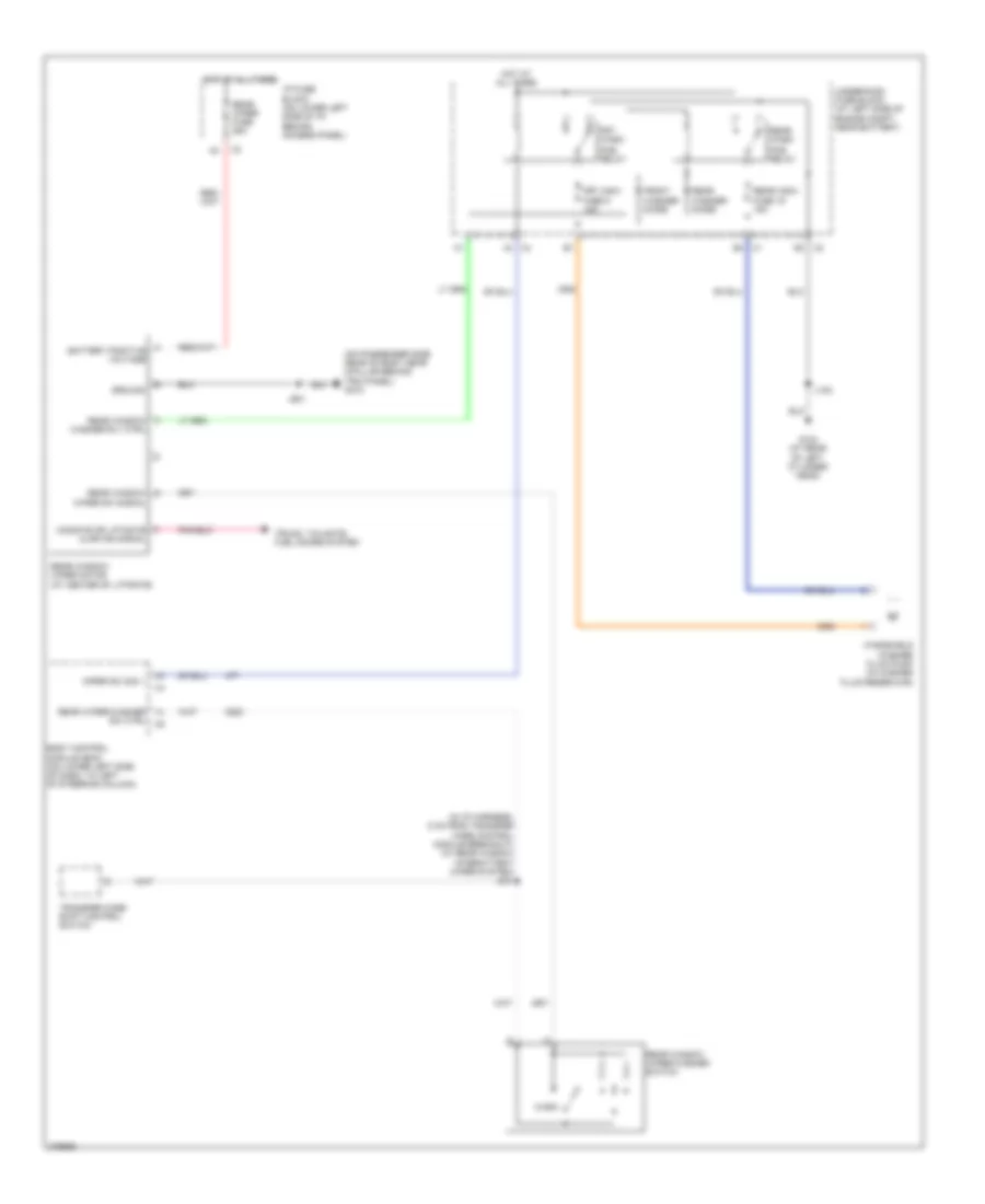 https://portal-diagnostov.com/license.html
Automotive Electricians Portal FZCO
Automotive Electricians Portal FZCO
https://portal-diagnostov.com/license.html
https://portal-diagnostov.com/license.html
Automotive Electricians Portal FZCO
Automotive Electricians Portal FZCOList of elements for Rear Wiper/Washer Wiring Diagram for Hummer H2 2008:
- (in i/p harness, 5 cm from transfer case control module breakout) (w/ rear window intermittent wiper system) j231
- (on passenger side rear of body near d-pillar behind trim panel) g410
- A battery positive voltage
- Ajar ind signal
- Body control module (bcm) (on lower left side of dash, to left of steering column)
- E4 x1
- Front washer diode
- Frt wash
- Frt wsw fuse 5 15a
- G104 (at rear of left cylinder head)
- Ground
- Hot at all times
- I/p fuse block (on lower left side of i/p, behind access panel)
- J102
- J901
- Midgate or liftgate f
- N5 x2
- Pcb relay
- Rear wash
- Rear washer diode
- Rear window c
- Rear window e
- Rear window wiper motor (at center of liftgate)
- Rear window wiper/washer switch
- Rear wiper fuse 25a
- Rear wiper/washer
- Rear wsw fuse 19 15a
- Sw ctrl x5
- Transfer case shift control switch
- Trunk, tailgate, fuel doors system
- Underhood fuse block (at left side of engine compt, near battery)
- Wash
- Washer rly ctrl
- Windshield washer fluid pump (in washer fluid reservoir)
- Wiper sw sig 1
- Wiper sw signal

 Čeština
 Dansk
Dansk Deutsch
 Ελληνικά
 English
 English
 Español
 Suomi
Suomi Français
 Français
 עברית
עברית Hrvatski
 Magyar
 Italiano
 日本語
日本語 Nederlands
 Polski
 Português
 Português
 Română
 Русский
 Slovenčina
 Slovenščina
 Svenska
 Türkçe
 中文 (中国)
