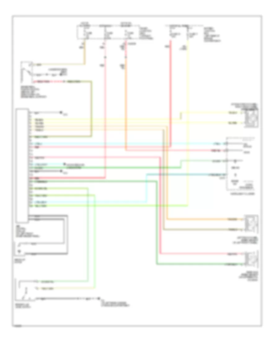
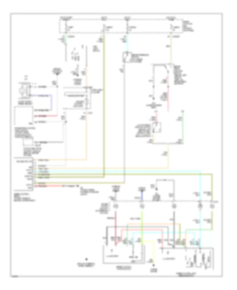
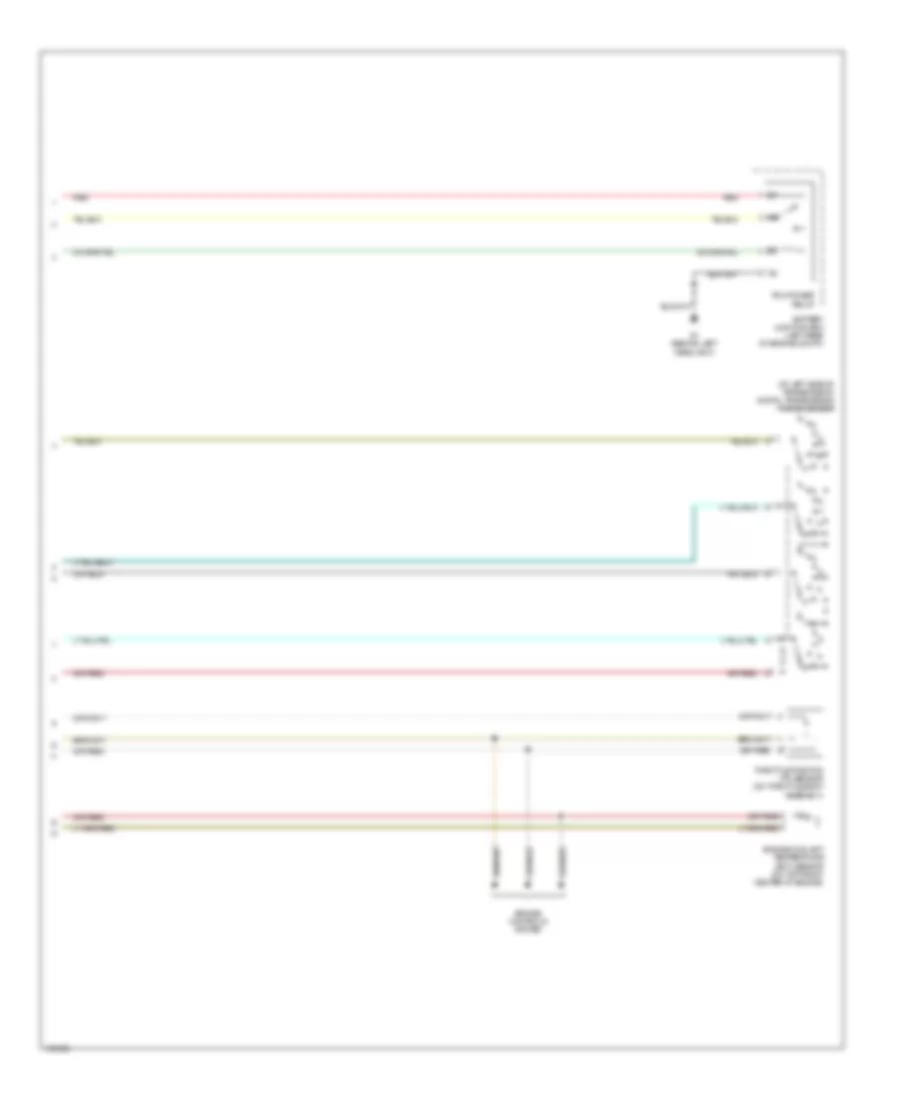
AIR CONDITIONING
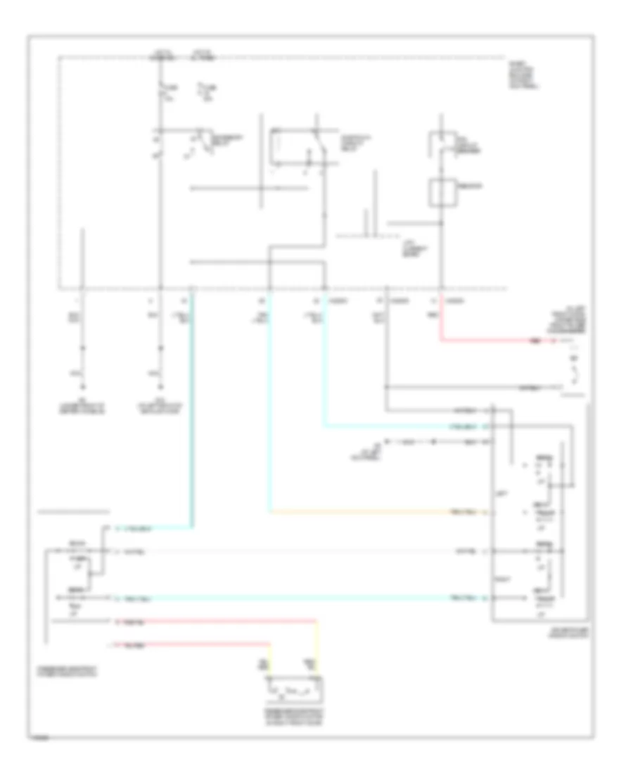
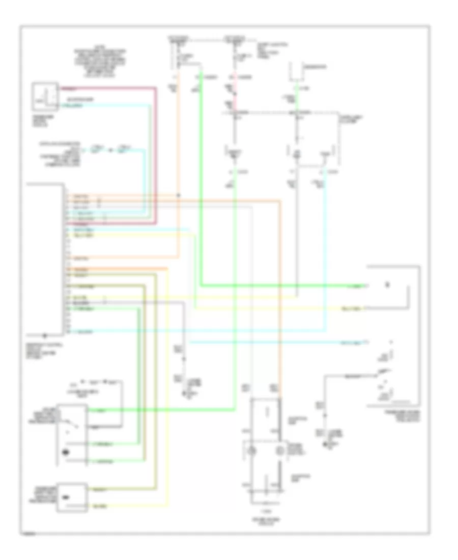
Manual A/C Wiring Diagram for Mazda BSE 2004 4000
 https://portal-diagnostov.com/license.html
Automotive Electricians Portal FZCO
Automotive Electricians Portal FZCO
https://portal-diagnostov.com/license.html
https://portal-diagnostov.com/license.html
Automotive Electricians Portal FZCO
Automotive Electricians Portal FZCO
List of elements for Manual A/C Wiring Diagram for Mazda BSE 2004 4000:
- (at left front corner of engine compt) g3
- (at left rear corner of engine compt) g3
- (behind left headlight) g1
- (under driver's seat)
- 2.3l
- A/c
- A/c clutch relay
- A/c clutch solenoid (at right front of engine)
- A/c compressor clutch diode
- A/c compressor cycling switch (in right side of engine compt, on a/c accumulator)
- A/c high pressure switch (at left front of engine compt)
- Battery junction box (left rear of engine compartment)
- Battery junction box (left rear of engine compt)
- Blend door actuator (behind right side of dash)
- Blower motor relay
- Blower motor switch
- Circuit breaker ptc
- Defrost
- Engine controls system
- Engine coolant temperature (ect) sensor (3.0l, 4.0l) (3.0l: on top left front of engine) (4.0l: on top front center of engine)
- Engine cooling fan motor (2.3l) (at right front of engine compt)
- Engine cooling fan relay (2.3l)
- Floor
- Flr/def
- Front function selector switch assembly
- Front heater blower motor resistor (right rear of engine compartment, near blower motor)
- Fuse 10a
- Fuse 20a
- Fuse 30a
- G-232
- G-233
- G-234
- G-235
- G10
- G3 (at left front corner of engine compt)
- G5 (at right rear corner of engine compt)
- Heater blower motor (right rear of engine compt, on firewall)
- Hot at all times
- Hot in on or start
- Hot in run
- Illumination
- Interior lights system
- Max a/c
- Med hi
- Med lo
- Mode switch
- Off
- Panel
- Pcm power diode
- Pcm power relay
- Powertrain control module (pcm) (right rear of engine compt, through firewall)
- Red
- Smart junction box (at right kick panel)
- Thermal limiter
ANTI-LOCK BRAKES
Anti-lock Brakes Wiring Diagram for Mazda BSE 2004 4000
 https://portal-diagnostov.com/license.html
Automotive Electricians Portal FZCO
Automotive Electricians Portal FZCO
https://portal-diagnostov.com/license.html
https://portal-diagnostov.com/license.html
Automotive Electricians Portal FZCO
Automotive Electricians Portal FZCOList of elements for Anti-lock Brakes Wiring Diagram for Mazda BSE 2004 4000:
- (at right front wheel) right front wheel speed sensor
- (under driver's seat) g10
- 4x4 status
- Abs control module (on left front inner fender panel)
- Abs ind
- Abs pump motor
- Battery junction box (left rear of engine compartment)
- Brake fluid level switch
- Brake ind
- Brake pedal position switch (behind left side of dash, on brake pedal support)
- C216
- Computer data lines system
- Fuse 10a
- Fuse 15 30a
- Fuse 17 40a
- Fuse 5a
- G12
- G3 (at left rear corner of engine compartment)
- Hot at all times
- Hot in on or start
- Hot in run
- Instrument cluster
- Left front wheel speed sensor (at left front wheel)
- Micro- processor
- Nca
- Rear axle speed sensor (on differential housing)
- Red
- Red red
- Red/pnk
- Smart junction box (at right kick panel)
- Vpwr
- X-2280b
ANTI-THEFT
Forced Entry Wiring Diagram for Mazda BSE 2004 4000
 https://portal-diagnostov.com/license.html
Automotive Electricians Portal FZCO
Automotive Electricians Portal FZCO
https://portal-diagnostov.com/license.html
https://portal-diagnostov.com/license.html
Automotive Electricians Portal FZCO
Automotive Electricians Portal FZCOList of elements for Forced Entry Wiring Diagram for Mazda BSE 2004 4000:
- (under driver's seat)
- Data link connector (dlc) (fastened to bottom of dash, near steering column)
- Door lock/
- Driver door lock relay
- Driver side door lock switch
- Driver side rear door ajar switch (at bottom front of left rear door)
- Driver's seat)
- Exterior lights system
- Fuse 15a
- Fuse 20a
- G10
- G10 (under
- G8 (under center of dash)
- G9 (at left kick panel)
- Horn relay
- Horns system
- Hot at all times
- Instrument cluster system
- Interior lights system
- Left front door ajar switch (at rear of left front door)
- Left front door lock actuator (at rear of left front door)
- Lock
- Main light switch
- Park lamp relay
- Passenger side door lock switch
- Passenger side rear door ajar switch (at bottom front of right rear door)
- Red
- Right front door ajar switch (at rear of right front door)
- Right front door lock actuator (at rear of right front door)
- Smart junction box (at right kick panel)
- Solid state
- Unlock
- Unlock relay
- X-2280a
- X-2280b
- X-2280c
- X-2280d
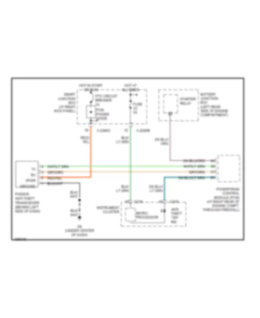
Passive Anti-theft Wiring Diagram for Mazda BSE 2004 4000
 https://portal-diagnostov.com/license.html
Automotive Electricians Portal FZCO
Automotive Electricians Portal FZCO
https://portal-diagnostov.com/license.html
https://portal-diagnostov.com/license.html
Automotive Electricians Portal FZCO
Automotive Electricians Portal FZCOList of elements for Passive Anti-theft Wiring Diagram for Mazda BSE 2004 4000:
- Anti- theft "on" ind
- Battery junction box (left rear side of engine compartment)
- C215
- C216
- Fuse 5a
- G8 (under center of dash)
- Ground
- Hot at all times
- Hot in start or run
- Instrument cluster
- Micro- processor
- Passive anti-theft transceiver (behind left side of dash)
- Pcm power diode
- Powertrain control module (pcm) (at right rear of engine compt, through firewall)
- Ptc circuit breaker 1a
- Smart junction box (at right kick panel)
- Starter relay
- Vpwr
- X-2280b
- X-2280c
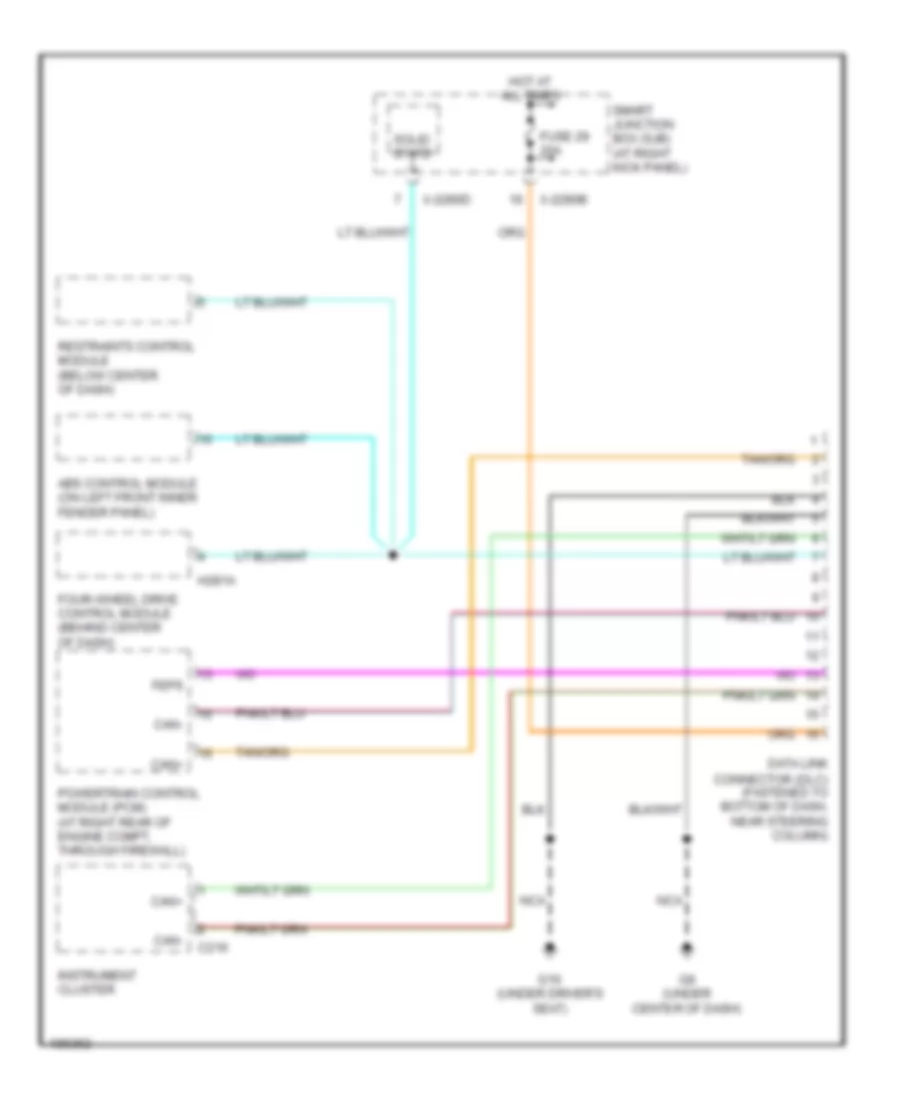
COMPUTER DATA LINES
Computer Data Lines Wiring Diagram for Mazda BSE 2004 4000
 https://portal-diagnostov.com/license.html
Automotive Electricians Portal FZCO
Automotive Electricians Portal FZCO
https://portal-diagnostov.com/license.html
https://portal-diagnostov.com/license.html
Automotive Electricians Portal FZCO
Automotive Electricians Portal FZCOList of elements for Computer Data Lines Wiring Diagram for Mazda BSE 2004 4000:
- Abs control module (on left front inner fender panel)
- C216
- Can+
- Can-
- Data link connector (dlc) (fastened to bottom of dash, near steering column)
- Feps
- Four-wheel drive control module (behind center of dash)
- Fuse 29 20a
- G10 (under driver's seat)
- G8 (under center of dash)
- H281a
- Hot at all times
- Instrument cluster
- Nca
- Powertrain control module (pcm) (at right rear of engine compt, through firewall)
- Restraints control module (below center of dash)
- Smart junction box (sjb) (at right kick panel)
- Solid state
- X-2280b
- X-2280d
CRUISE CONTROL
Cruise Control Wiring Diagram for Mazda BSE 2004 4000
 https://portal-diagnostov.com/license.html
Automotive Electricians Portal FZCO
Automotive Electricians Portal FZCO
https://portal-diagnostov.com/license.html
https://portal-diagnostov.com/license.html
Automotive Electricians Portal FZCO
Automotive Electricians Portal FZCOList of elements for Cruise Control Wiring Diagram for Mazda BSE 2004 4000:
- 10a
- A/t
- Air bag sliding contact (on steering column)
- Brake pedal position switch (behind left side of dash, on brake pedal support)
- Brake pressure switch (at master cylinder)
- C215
- C219
- C2280b
- C2280c
- Clutch pedal position switch (behind left side of dash, top of clutch pedal support)
- Coast(-)
- Cruise control indicator
- Cruise ctrl ind
- Engine controls system
- Four-wheel drive control module (behind center of dash)
- Fuse 20
- Fuse 26
- Fuse 32
- Fuse 7
- G10 (under driver's seat)
- G5 (at right rear corner of engine compt)
- G8 (under center of dash)
- Gnd
- Ground steering wheel assembly
- H281b
- Head
- Horns system
- Hot at all times
- Hot in run
- Hot in start or run
- Illumination
- In put
- Instrument cluster
- Interior lights system
- M/t
- Main light switch
- Microcomputer
- Nca
- Off
- Output shaft speed sensor
- Park
- Powertrain control module (pcm) (at right rear of engine compt, through firewall)
- Rest
- Resume
- Set(+)
- Sig rtn
- Smart junction box (at right kick panel)
- Speed control servo (in right rear of engine compartment)
- Speed control on/off switch
- Speed control set/ resume switch
- Vpwr
- Vref
- Vss
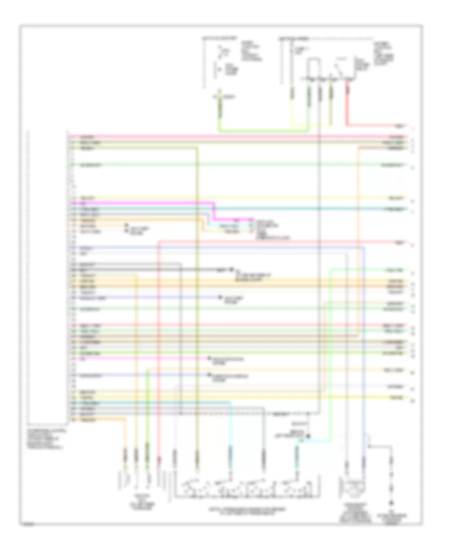
ENGINE PERFORMANCE
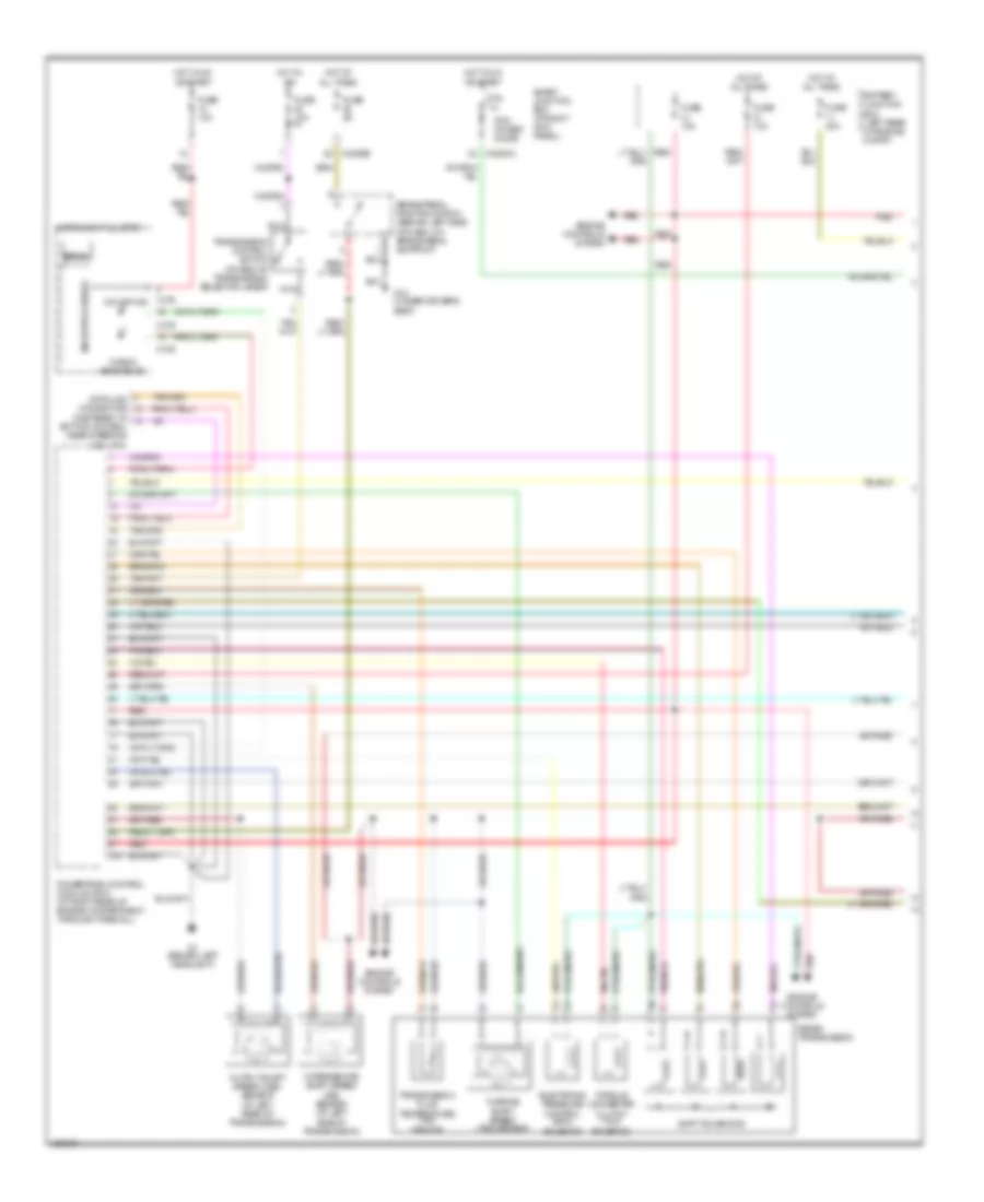
Engine Performance Wiring Diagram (1 of 4) for Mazda BSE 2004 4000
 https://portal-diagnostov.com/license.html
Automotive Electricians Portal FZCO
Automotive Electricians Portal FZCO
https://portal-diagnostov.com/license.html
https://portal-diagnostov.com/license.html
Automotive Electricians Portal FZCO
Automotive Electricians Portal FZCOList of elements for Engine Performance Wiring Diagram (1 of 4) for Mazda BSE 2004 4000:
- (behind left headlight)
- (near steering column)
- Air conditioning system
- Anti-theft system
- Battery junction box (left rear of engine compt)
- Crankshaft position (ckp) sensor (on lower right front of engine)
- Data link connector (dlc)
- Digital transmission range (dtr) sensor (at left side of transmission)
- Fuse 11 30a
- G2 (at center rear of engine compt)
- Hot at all times
- Hot in on or start
- Ignition coil (on left rear of engine)
- Pcm power diode
- Pcm power relay
- Powertrain control module (pcm) (at right rear of engine compt, through firewall)
- Ptc 1a
- Red
- Smart junction box (at right kick panel)
- Starting/charging system
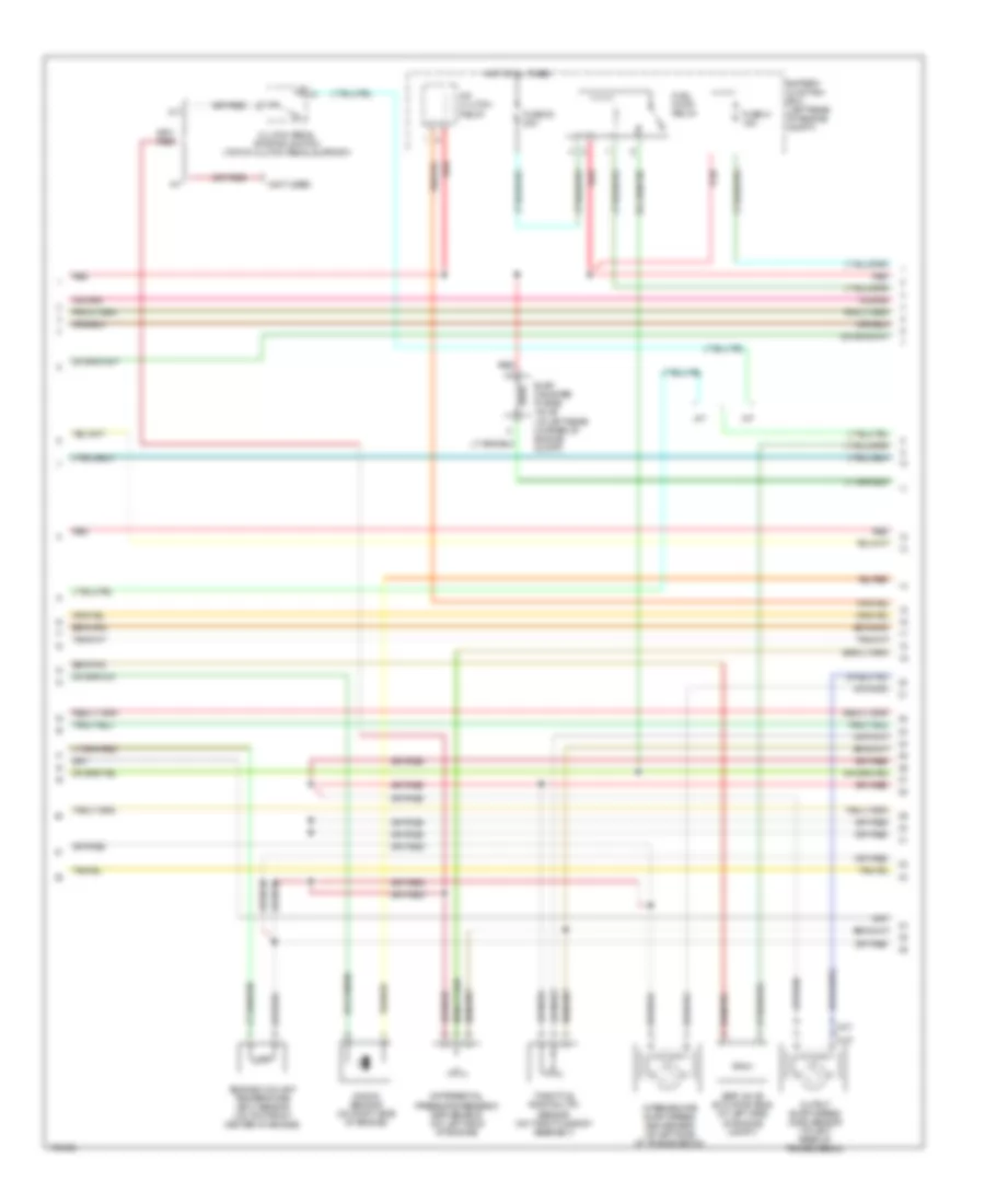
Engine Performance Wiring Diagram (2 of 4) for Mazda BSE 2004 4000
 https://portal-diagnostov.com/license.html
Automotive Electricians Portal FZCO
Automotive Electricians Portal FZCO
https://portal-diagnostov.com/license.html
https://portal-diagnostov.com/license.html
Automotive Electricians Portal FZCO
Automotive Electricians Portal FZCOList of elements for Engine Performance Wiring Diagram (2 of 4) for Mazda BSE 2004 4000:
- (a/t)
- (m/t)
- (not used)
- A/c clutch relay
- A/t
- Battery junction box (left rear of engine compt)
- Clutch pedal position switch (top of clutch pedal support)
- Differential pressure feedback egr sensor (on left side of engine)
- Egr valve actuator (ecs) (at left side of engine compt)
- Engine coolant temperature (ect) sensor (on top front center of engine)
- Evap canister purge valve (at left rear corner of engine compt)
- Fuel pump relay
- Fuse 23 20a
- Fuse 41 15a
- Hot at all times
- Intermediate shaft speed (iss) sensor (at left side of transmission)
- Knock sensor (on right side of engine)
- M/t
- Output shaft speed (oss) sensor (at left rear of transmission)
- Red
- Throttle position (tp) sensor (on throttle body assembly)
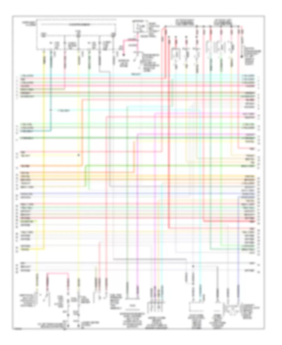
Engine Performance Wiring Diagram (3 of 4) for Mazda BSE 2004 4000
 https://portal-diagnostov.com/license.html
Automotive Electricians Portal FZCO
Automotive Electricians Portal FZCO
https://portal-diagnostov.com/license.html
https://portal-diagnostov.com/license.html
Automotive Electricians Portal FZCO
Automotive Electricians Portal FZCOList of elements for Engine Performance Wiring Diagram (3 of 4) for Mazda BSE 2004 4000:
- (at left rear corner of engine compartment) g3
- (at top of left cylinder bank) fuel injectors
- (at top of right cylinder bank) fuel injectors
- (under center of dash) g8
- 4wd low ind
- C215
- C216
- Camshaft position (cmp) sensor (on left side of engine)
- Check engine ind
- Check fuel cap ind
- Evaporative emission (evap) canister vent valve (under vehicle, on frame cross support)
- Exterior lights system
- Four wheel drive control module (behind center of dash)
- Fuel gauge sensor
- Fuel lev sig
- Fuel pump
- Fuel tank pressure sensor (at fuel tank assembly)
- Fuel tank unit (in fuel tank
- Fuse 10a
- H281b
- Heated oxygen sensor (ho2s) 22 (at right rear of engine, in exhaust)
- Hot in on
- Ignition transformer capacitor 1 (at left rear of engine compt)
- Inertia fuel shut-off (ifs) switch (in right kick panel)
- Instrument cluster
- Microprocessor
- Nca
- O/d off ind
- Red
- Red/pnk
- Smart junction box (at right kick panel) x2280b
- Speed control servo (in right rear of engine compt)
- Tach sig
- Tan
- Transmission control switch (on end of transmission selector lever)
- Vss sig
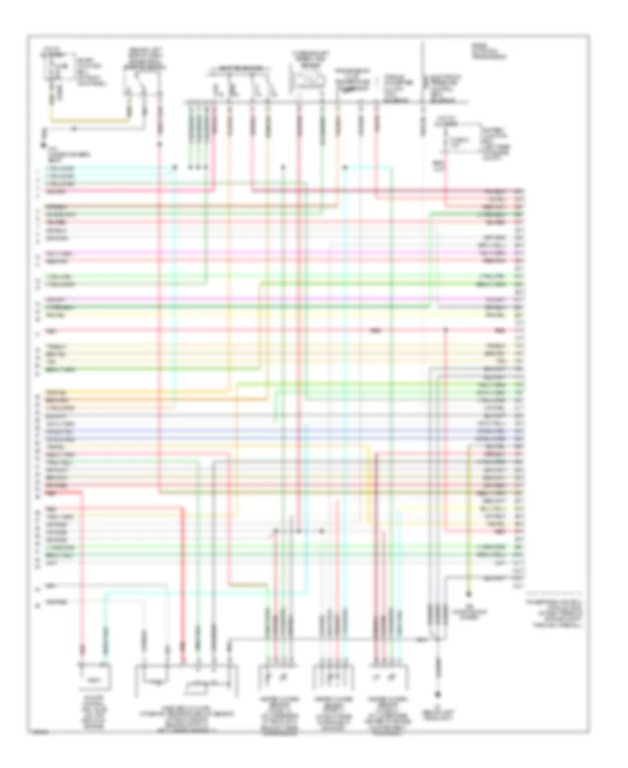
Engine Performance Wiring Diagram (4 of 4) for Mazda BSE 2004 4000
 https://portal-diagnostov.com/license.html
Automotive Electricians Portal FZCO
Automotive Electricians Portal FZCO
https://portal-diagnostov.com/license.html
https://portal-diagnostov.com/license.html
Automotive Electricians Portal FZCO
Automotive Electricians Portal FZCOList of elements for Engine Performance Wiring Diagram (4 of 4) for Mazda BSE 2004 4000:
- (behind left side of dash) brake pedal position switch
- 5r55e automatic transmission
- Air conditioning system
- Battery junction box (left rear of engine compt)
- Electronic pressure control (epc) solenoid
- Fuse 21 10a
- Fuse 5a
- G1 (behind left headlight)
- G10 (under driver's seat)
- Heated oxygen sensor (ho2s) 11 (in right rear of engine, in exhaust)
- Heated oxygen sensor (ho2s) 12 (at underside of vehicle, in exhaust, near transmission)
- Heated oxygen sensor (ho2s) 21 (at lower rear center of engine compartment, in exhaust)
- Hot at all times
- Idle air control (iac) valve (on top front of engine)
- Mass airflow (maf)/ intake air temperature (iat) sensor (at right side of engine compt, in air cleaner assembly)
- Powertrain control module (pcm) (at right rear of engine compt, through firewall)
- Red
- Red/pnk
- Shift solenoids
- Smart junction box (at right kick panel)
- Tan
- Torque converter clutch (tcc) solenoid
- Transmission fluid temperature (tft) sensor
- Turbine shaft speed (tss) sensor
- X2280b
EXTERIOR LIGHTS
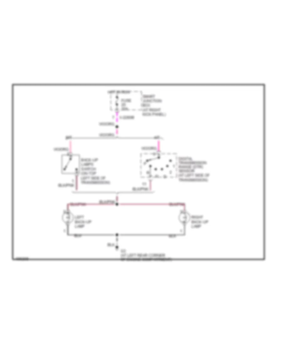
Back-up Lamps Wiring Diagram for Mazda BSE 2004 4000
 https://portal-diagnostov.com/license.html
Automotive Electricians Portal FZCO
Automotive Electricians Portal FZCO
https://portal-diagnostov.com/license.html
https://portal-diagnostov.com/license.html
Automotive Electricians Portal FZCO
Automotive Electricians Portal FZCOList of elements for Back-up Lamps Wiring Diagram for Mazda BSE 2004 4000:
- A/t
- Back-up lamps switch (on top left side of transmission)
- Digital transmission range (dtr) sensor (at left side of transmission)
- Fuse 10a
- G3 (at left rear corner of engine compartment)
- Hot in run
- Left back-up lamp
- M/t
- Right back-up lamp
- Smart junction box (at right kick panel)
- X-2280b
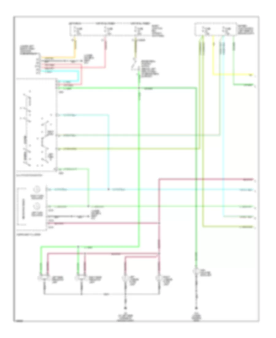
Exterior Lamps Wiring Diagram (1 of 2) for Mazda BSE 2004 4000
 https://portal-diagnostov.com/license.html
Automotive Electricians Portal FZCO
Automotive Electricians Portal FZCO
https://portal-diagnostov.com/license.html
https://portal-diagnostov.com/license.html
Automotive Electricians Portal FZCO
Automotive Electricians Portal FZCOList of elements for Exterior Lamps Wiring Diagram (1 of 2) for Mazda BSE 2004 4000:
- (under driver's seat) g10
- (under left side of dash) indicator flasher relay
- 87a
- Battery junction box (left rear of engine compt)
- Brake pedal position switch (behind left side of dash, on brake pedal support)
- C215
- C216
- Fuse 10a
- Fuse 15a
- Fuse 20a
- Fuse 7.5a
- G10 (under driver's seat)
- G3 (at left rear corner of engine compt)
- Hazard
- High mounted stoplamp
- Hot at all times
- Hot in run
- Instrument cluster
- Left license plate lamp
- Left rear park/stop lamp
- Left turn
- Left turn indicator
- Microprocessor
- Multi-function switch
- Normal
- Right license plate lamp
- Right rear park/stop lamp
- Right turn
- Right turn indicator
- Smart junction box (at right kick panel)
- X-2280b
- X253
- X254
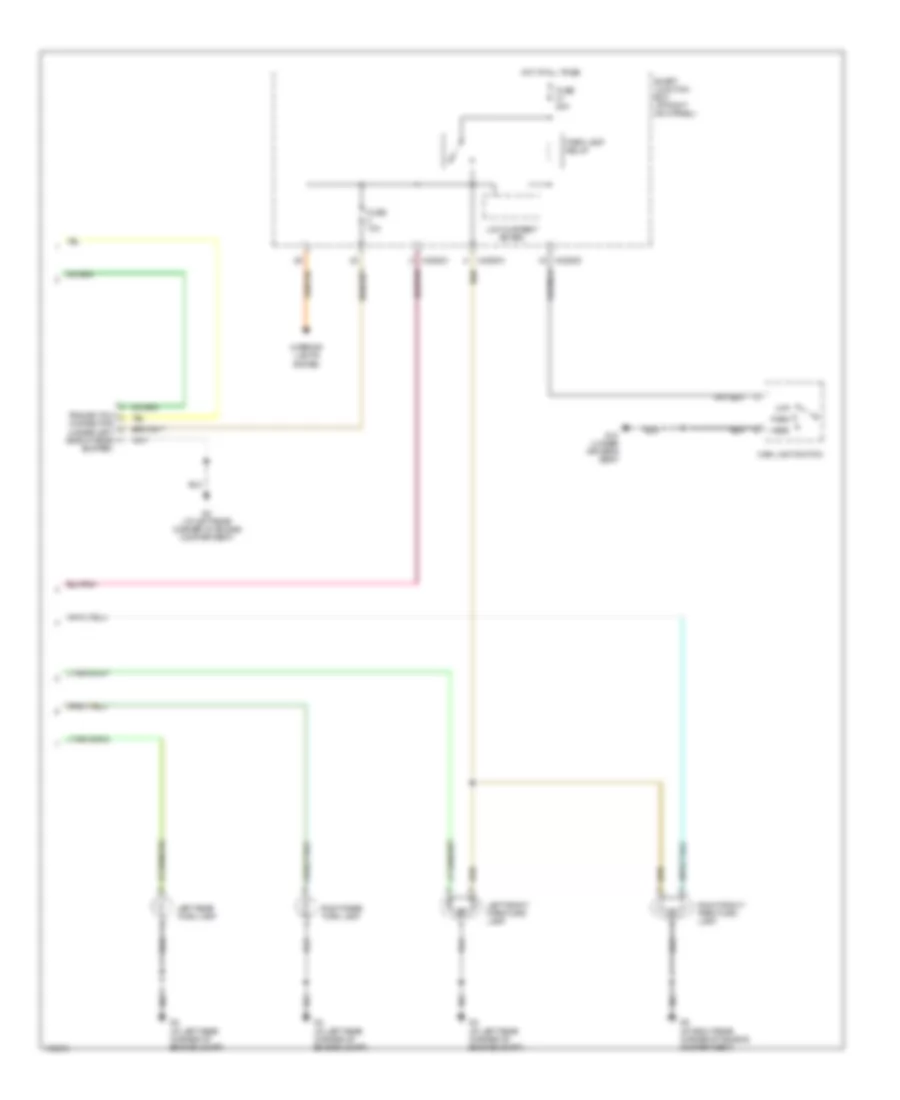
Exterior Lamps Wiring Diagram (2 of 2) for Mazda BSE 2004 4000
 https://portal-diagnostov.com/license.html
Automotive Electricians Portal FZCO
Automotive Electricians Portal FZCO
https://portal-diagnostov.com/license.html
https://portal-diagnostov.com/license.html
Automotive Electricians Portal FZCO
Automotive Electricians Portal FZCOList of elements for Exterior Lamps Wiring Diagram (2 of 2) for Mazda BSE 2004 4000:
- Bumper)
- Connector (under left side of rear
- Fuse 10a
- Fuse 20a
- G10 (under driver's seat)
- G3 (at left rear corner of engine compartment)
- G3 (at left rear corner of engine compt)
- G5 (at right rear corner of engine compartment)
- Head
- Hot at all times
- Interior lights system
- Left front park/turn lamp
- Left rear turn lamp
- Low current board
- Main light switch
- Off
- Park
- Park lamp relay
- Right front park/turn lamp
- Right rear turn lamp
- Smart junction box (at right kick panel)
- Trailer tow
- X-2280a
- X-2280c
- X-2280d
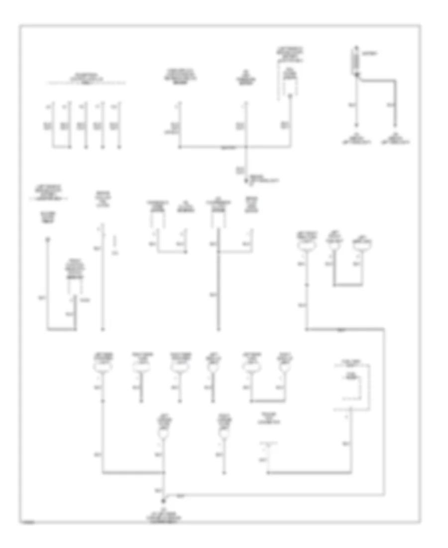
GROUND DISTRIBUTION
Ground Distribution Wiring Diagram (1 of 3) for Mazda BSE 2004 4000
 https://portal-diagnostov.com/license.html
Automotive Electricians Portal FZCO
Automotive Electricians Portal FZCO
https://portal-diagnostov.com/license.html
https://portal-diagnostov.com/license.html
Automotive Electricians Portal FZCO
Automotive Electricians Portal FZCOList of elements for Ground Distribution Wiring Diagram (1 of 3) for Mazda BSE 2004 4000:
- (behind left headlight) g1
- (left rear of engine compt) battery junction box
- 2.3l
- A/c clutch solenoid
- A/c compressor clutch diode
- A/c high pressure switch
- Battery
- Blower motor relay
- Brake fluid level switch
- Engine cooling fan motor
- Front function selection switch assembly
- Fuel pump
- Fuel tank unit
- G-232
- G3 (at left rear corner of engine compartment)
- G4 (behind left headlight)
- G6 (behind left headlight)
- Left back-up light
- Left front foglight
- Left front park/turn light
- Left headlight
- Left license plate light
- Left rear stop/park light
- Left rear turn light
- Mass airflow (maf)/intake air temperature (iat) sensor
- Pcm power relay
- Powertrain control module (pcm)
- Right back-up light
- Right license plate light
- Right rear stop/park light
- Right rear turn light
- Trailer tow connector
- Windshield wiper motor
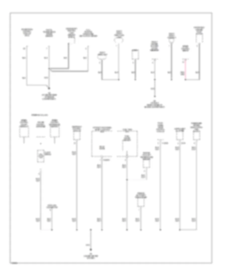
Ground Distribution Wiring Diagram (2 of 3) for Mazda BSE 2004 4000
 https://portal-diagnostov.com/license.html
Automotive Electricians Portal FZCO
Automotive Electricians Portal FZCO
https://portal-diagnostov.com/license.html
https://portal-diagnostov.com/license.html
Automotive Electricians Portal FZCO
Automotive Electricians Portal FZCOList of elements for Ground Distribution Wiring Diagram (2 of 3) for Mazda BSE 2004 4000:
- (3.0l) positive crankcase ventilation heater
- (at right kick panel) smart junction box
- C216
- Clock spring
- Crankshaft position (ckp) sensor shield
- Cruise control switches
- Data link connector
- Digital transmission range sensor
- Engine coolant temperature sender
- Four- wheel drive control module
- Front heater blower motor resistor
- Fuel gauge sensor
- Fuel tank unit
- G2 (at center rear of engine compartment)
- G5 (at right rear corner of engine compartment)
- G8 (under center of dash)
- H-281b
- Horn
- Instrument cluster
- Nca
- Passenger air bag deactivation (pad) switch
- Passive anti-theft transceiver
- Powertrain control module (pcm)
- Restraint control module
- Right front foglight
- Right front park/turn light
- Right headlight
- Solid state
- Speed control on/off switch
- Speed control servo
- Speed control set/resume switch
- Steering column
- Windshield washer pump motor
- X-2280c
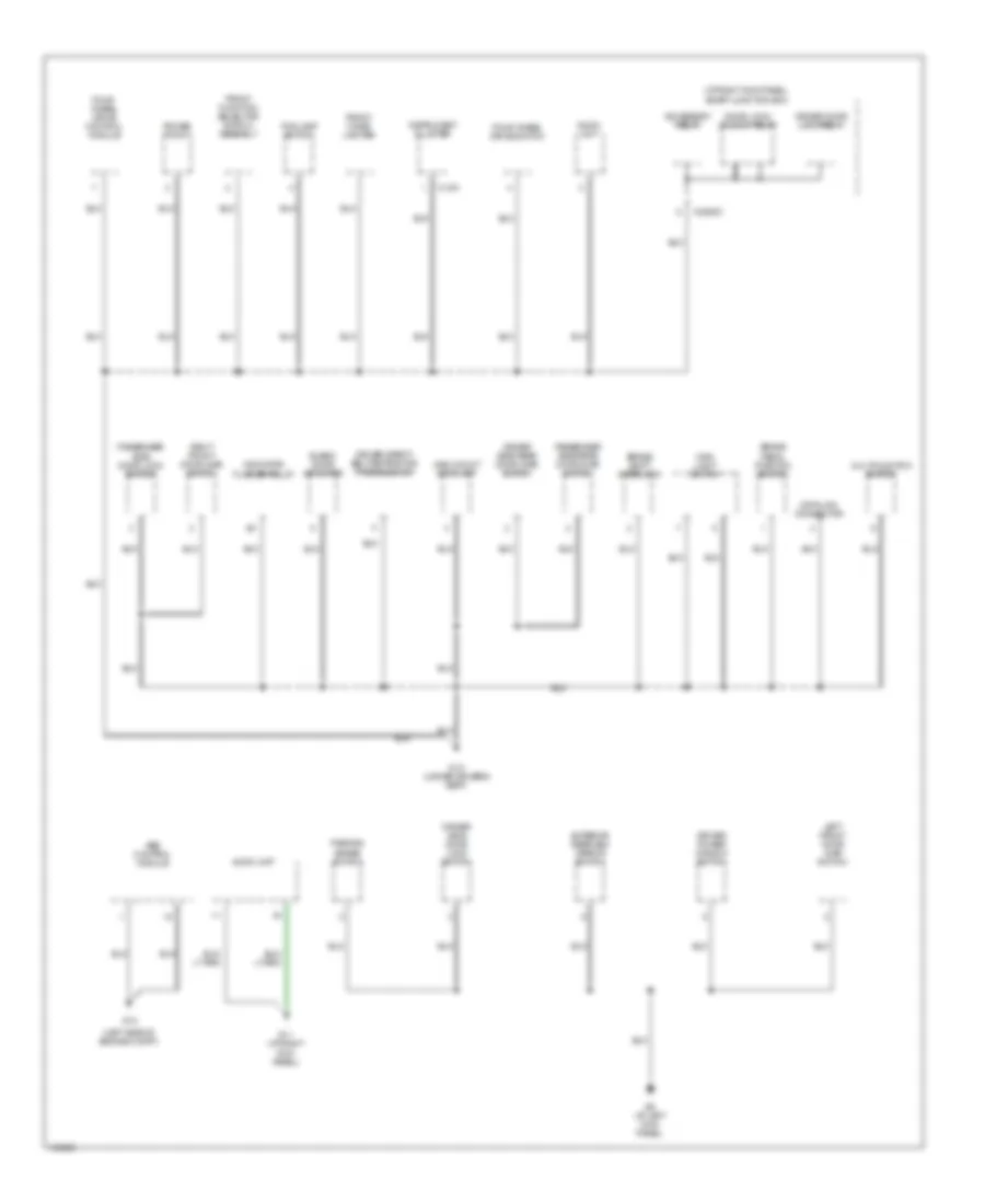
Ground Distribution Wiring Diagram (3 of 3) for Mazda BSE 2004 4000
 https://portal-diagnostov.com/license.html
Automotive Electricians Portal FZCO
Automotive Electricians Portal FZCO
https://portal-diagnostov.com/license.html
https://portal-diagnostov.com/license.html
Automotive Electricians Portal FZCO
Automotive Electricians Portal FZCOList of elements for Ground Distribution Wiring Diagram (3 of 3) for Mazda BSE 2004 4000:
- (at right kick panel) smart junction box
- (left side of engine compt)
- Abs control module
- Accessory relay
- Audio unit
- Blend door actuator
- Brake pedal position switch
- Brake shift interlock
- C-215
- Data link connector
- Door lock/ unlock relay
- Driver door lock relay
- Driver power window switch
- Driver safety belt retractor pretensioner
- Driver side door lock switch
- Driver side rear door ajar switch
- Exterior rearview mirror switch
- Fog lamp switch
- Four wheel drive switch
- Four- wheel drive control module
- Front cigar lighter
- Front function selector switch assembly
- G10 (under driver's seat)
- G11 (at right kick panel)
- G12
- G9 (at left kick panel)
- High mount stoplamp
- Indicator flasher relay
- Instrument cluster
- Left front door ajar switch
- Main light switch
- Multifunction switch
- Parking brake switch
- Passenger side door lock switch
- Passenger side rear door ajar switch
- Power point
- Right front door ajar switch
- X-2280c
HEADLIGHTS
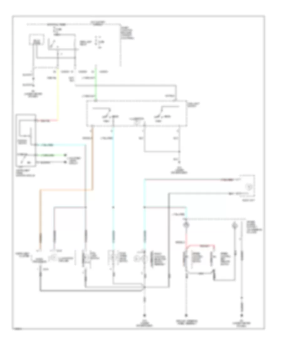
Headlights Wiring Diagram, with DRL for Mazda BSE 2004 4000
 https://portal-diagnostov.com/license.html
Automotive Electricians Portal FZCO
Automotive Electricians Portal FZCO
https://portal-diagnostov.com/license.html
https://portal-diagnostov.com/license.html
Automotive Electricians Portal FZCO
Automotive Electricians Portal FZCOList of elements for Headlights Wiring Diagram, with DRL for Mazda BSE 2004 4000:
- Battery junction box (left rear of engine compt)
- C-216
- Drl
- Flash to pass
- Fog lamp relay
- Fog lamp switch
- Fuse 10a
- Fuse 15a
- Fuse 30a
- G10 (under driver's seat)
- G3 (at left rear corner of engine compt)
- G5 (at right rear corner of engine compt)
- G8 (under center of dash)
- G9 (at left kick panel)
- Head
- High
- High beam ind
- Hot at all times
- Instrument cluster
- Interior lights system
- Left front fog lamp
- Left head- lamp
- Low
- Main light switch
- Microprocessor
- Multi-function switch
- Nca
- Off
- Park
- Parking brake switch (below left side of dash, on park brake assembly)
- Right front fog lamp
- Right head- lamp
- Smart junction box (at right kick panel)
- Solid state
- X-2280a
- X-2280b
- X-2280c
- X-2280d
- X-254
Headlights Wiring Diagram, without DRL for Mazda BSE 2004 4000
 https://portal-diagnostov.com/license.html
Automotive Electricians Portal FZCO
Automotive Electricians Portal FZCO
https://portal-diagnostov.com/license.html
https://portal-diagnostov.com/license.html
Automotive Electricians Portal FZCO
Automotive Electricians Portal FZCOList of elements for Headlights Wiring Diagram, without DRL for Mazda BSE 2004 4000:
- Battery junction box (left rear of engine compt)
- C-216
- Flash to pass
- Fog lamp relay
- Fog lamp switch
- Fuse 10a
- Fuse 15a
- Fuse 30a
- G10 (under driver's seat)
- G3 (at left rear corner of engine compt)
- G5 (at right rear corner of engine compt)
- G8 (under center of dash)
- Head
- High
- High beam ind
- Hot at all times
- Instrument cluster
- Interior lights system
- Left front fog lamp
- Left head- lamp
- Low
- Main light switch
- Microprocessor
- Multi-function switch
- Nca
- Off
- Park
- Right front fog lamp
- Right head- lamp
- Smart junction box (at right kick panel)
- Solid state
- X-2280a
- X-2280b
- X-2280c
- X-2280d
- X-254
HORN
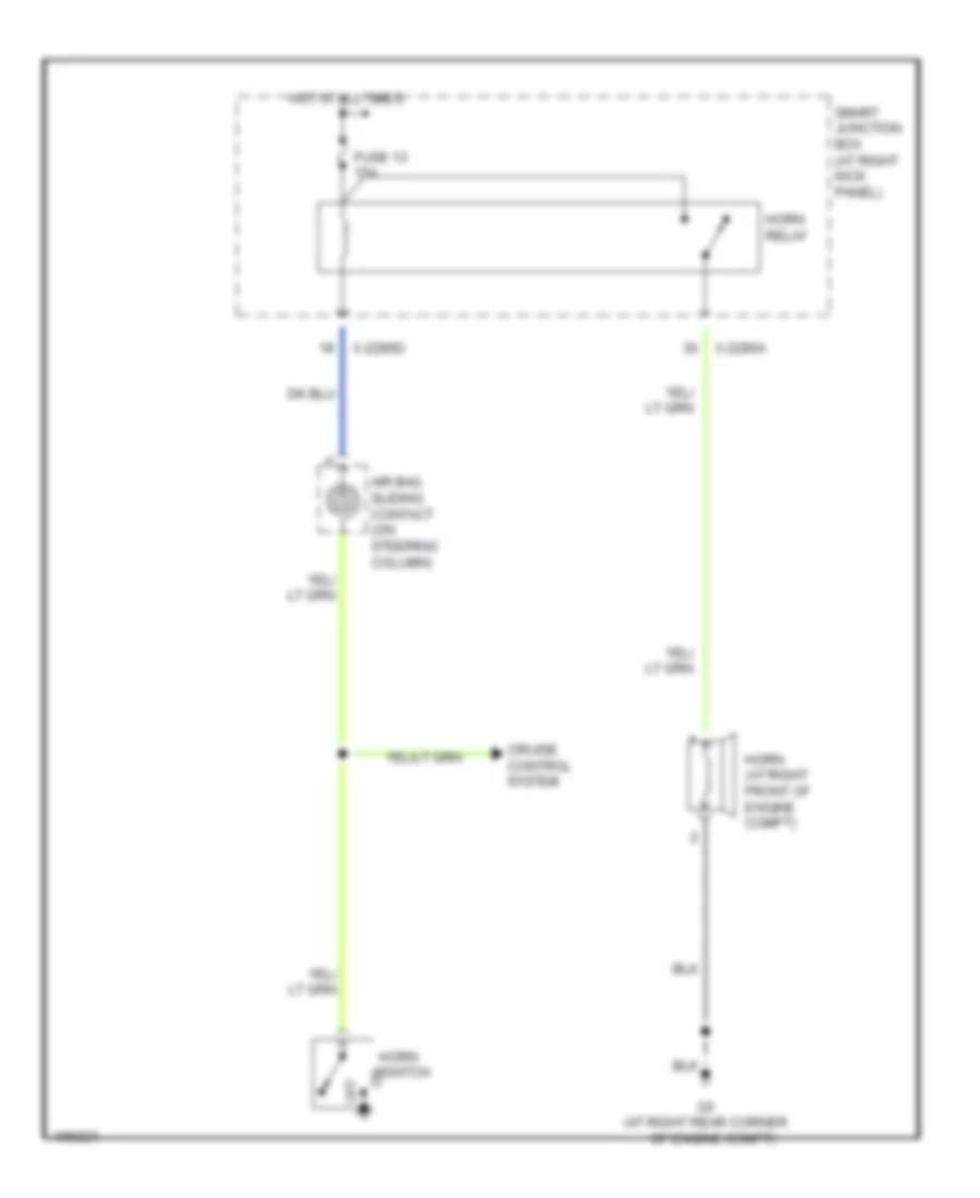
Horn Wiring Diagram for Mazda BSE 2004 4000
 https://portal-diagnostov.com/license.html
Automotive Electricians Portal FZCO
Automotive Electricians Portal FZCO
https://portal-diagnostov.com/license.html
https://portal-diagnostov.com/license.html
Automotive Electricians Portal FZCO
Automotive Electricians Portal FZCOList of elements for Horn Wiring Diagram for Mazda BSE 2004 4000:
- Air bag sliding contact (on steering column)
- Cruise control system
- Fuse 13 15a
- G5 (at right rear corner
- Horn (at right front of engine compt)
- Horn relay
- Horn switch
- Hot at all times
- Of engine compt)
- Off
- Smart junction box (at right kick panel)
- X-2280a
- X-2280d
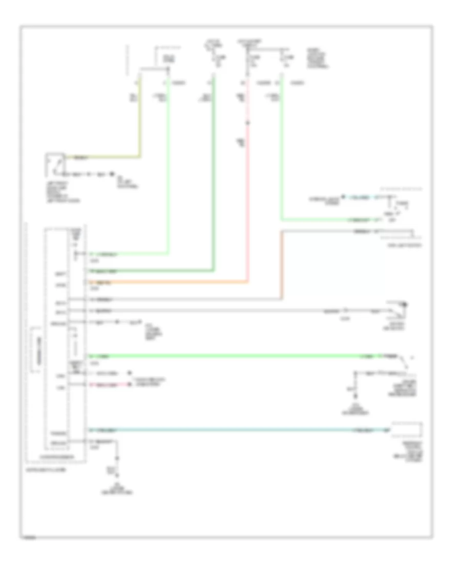
INSTRUMENT CLUSTER
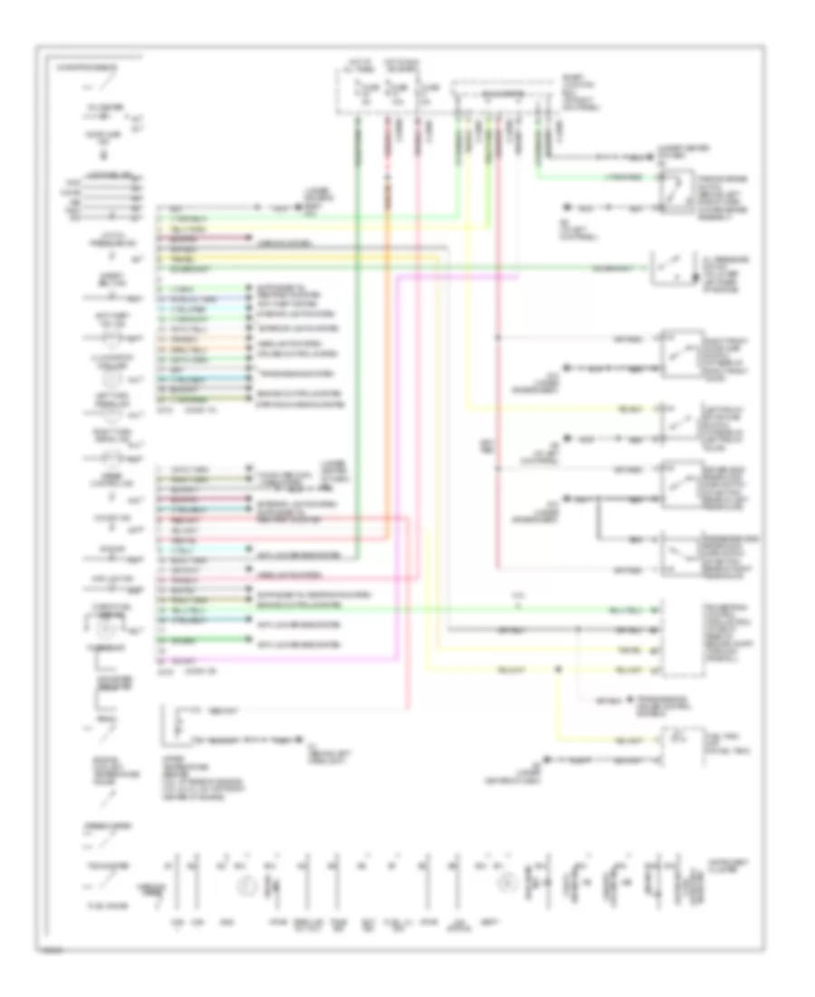
Instrument Cluster Wiring Diagram for Mazda BSE 2004 4000
 https://portal-diagnostov.com/license.html
Automotive Electricians Portal FZCO
Automotive Electricians Portal FZCO
https://portal-diagnostov.com/license.html
https://portal-diagnostov.com/license.html
Automotive Electricians Portal FZCO
Automotive Electricians Portal FZCOList of elements for Instrument Cluster Wiring Diagram for Mazda BSE 2004 4000:
- (conn "a")
- (conn "b")
- (under center of dash) g8
- (under driver's seat) g10
- 2.3l
- 4wd ind
- 4wd low ind
- 4x4 status
- A10
- A11
- A12
- A13
- A14
- A15
- A16
- A17
- A18
- A19
- A20
- Abs ind
- Air bag ind
- Anti-lock brakes system
- Anti-theft "on" ind
- Anti-theft system
- B10
- B11
- B12
- B13
- B14
- B15
- B16
- B18
- B20
- C215
- C216
- Can +
- Can -
- Charge ind
- Check engine ind
- Check fuel cap ind
- Chime
- Computer data lines system
- Cruise control system
- Door ajar ind
- Driver side rear door ajar switch (at bottom rear of left rear door)
- Ect sig
- Engine controls system
- Engine coolant temperature gauge
- Exterior lights system
- Failsafe cooling ind
- Fuel gauge
- Fuel lvl sig
- Fuel tank unit (in fuel tank)
- Fuse 10a
- Fuse 5a
- G1 (behind left headlight)
- G10 (under driver's seat)
- G8 (under center of dash)
- G9 (at left kick panel)
- Gnd
- Headlights system
- High beam ind
- Hot at all times
- Hot in run or start
- Illumination (6 bulbs)
- Instrument cluster
- Interior lights system
- Left front door ajar switch (at rear of left front door)
- Left turn signal ind
- Low brake fluid level/park brake ind
- Low fuel ind
- Low oil pressure ind
- Microprocessor
- Nca
- O/d off ind
- Odometer/ tripmeter
- Oil pressure switch (on lower left rear of engine)
- Park lmp rly out
- Parking brake switch (behind left side of dash, on park brake assembly)
- Passenger side rear door ajar switch (at bottom rear of right rear door)
- Powertrain control module (pcm) (at right rear of engine compt, through firewall)
- Prndl
- Right front door ajar switch (at rear of right front door)
- Right turn signal ind
- Safety belt ind
- Smart junction box (at right kick panel)
- Solid stste
- Speed control ind
- Speedometer
- Starting/charging system
- Tach sig
- Tachometer
- Tone sig
- Transmissions system
- Transmissions, cruise control systems
- Vbatt
- Voltmeter
- Vpwr
- Vss
- Warning chime
- Warning system
- Water temperature sender (2.3l: at rear of engine) (3.0l & 4.0l: on top front center of engine)
- X-2280b
- X-2280c
- X-2280d
INTERIOR LIGHTS
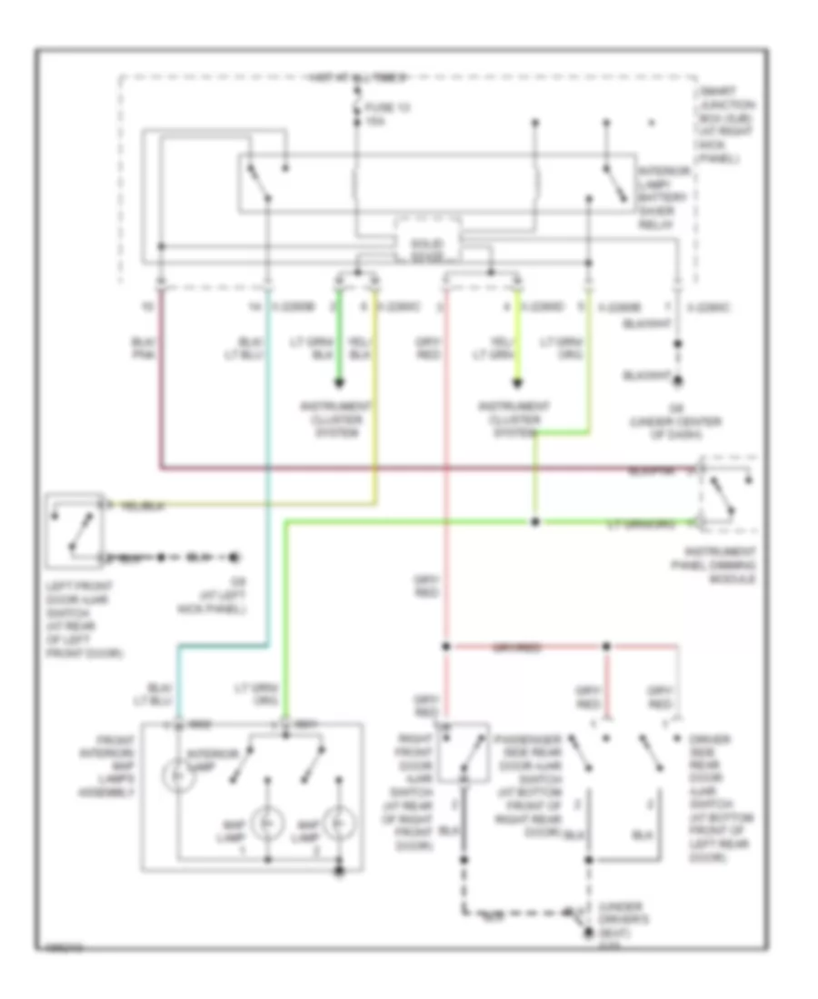
Courtesy Lamps Wiring Diagram for Mazda BSE 2004 4000
 https://portal-diagnostov.com/license.html
Automotive Electricians Portal FZCO
Automotive Electricians Portal FZCO
https://portal-diagnostov.com/license.html
https://portal-diagnostov.com/license.html
Automotive Electricians Portal FZCO
Automotive Electricians Portal FZCOList of elements for Courtesy Lamps Wiring Diagram for Mazda BSE 2004 4000:
- Driver side rear door ajar switch (at bottom front of left rear door)
- Driver's seat) g10
- Front interior/ map lamps assembly
- Fuse 13 15a
- G8 (under center of dash)
- G9 (at left kick panel)
- Hot at all times
- I901
- I902
- Instrument cluster system
- Instrument panel dimming module
- Interior lamp
- Interior lamp/ battery saver relay
- Left front door ajar switch (at rear of left front door)
- Map lamp
- Passenger side rear door ajar switch (at bottom front of right rear door)
- Right front door ajar switch (at rear of right front door)
- Smart junction box (sjb) (at right kick panel)
- Solid state
- X-2280b
- X-2280c
- X-2280d
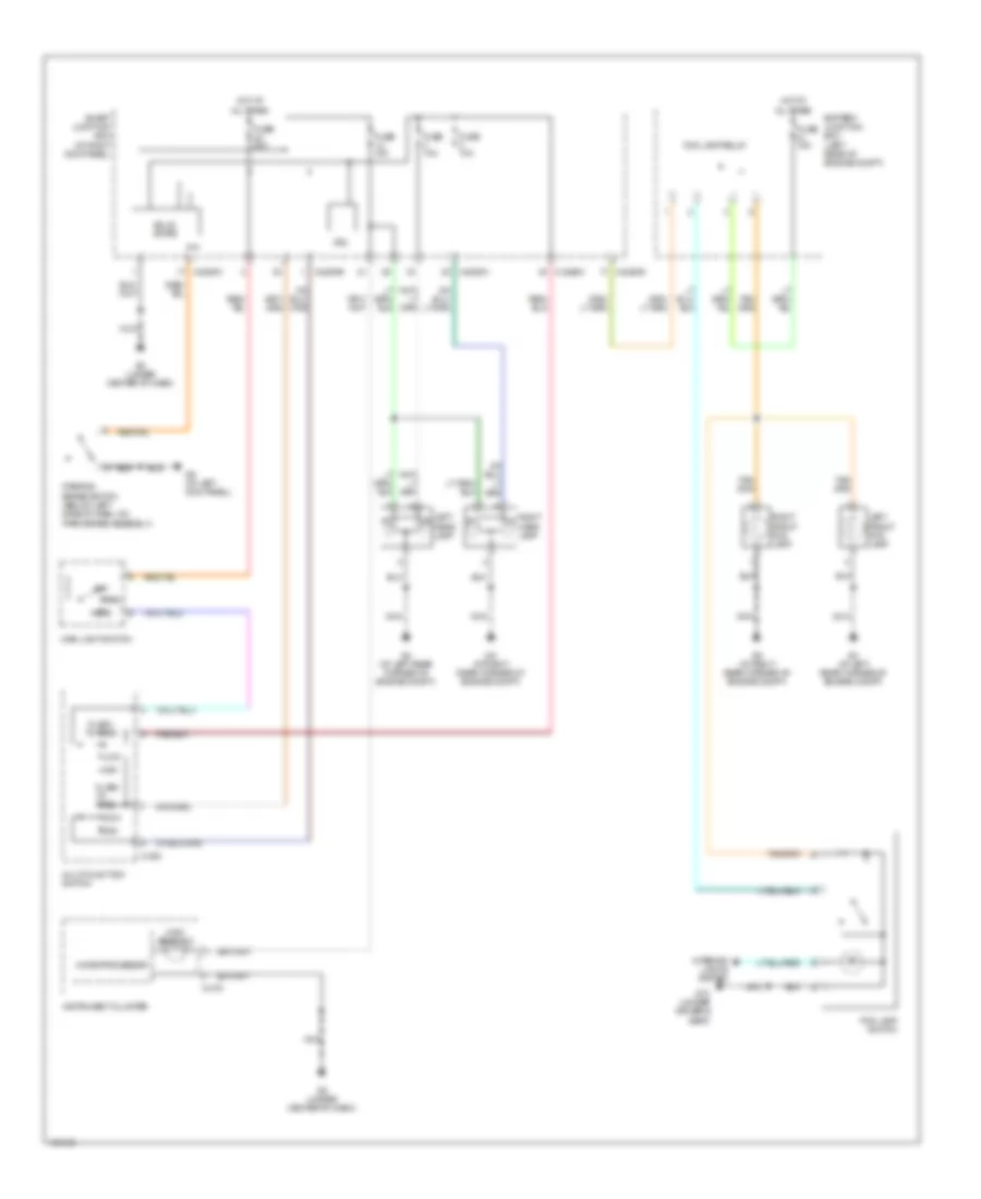
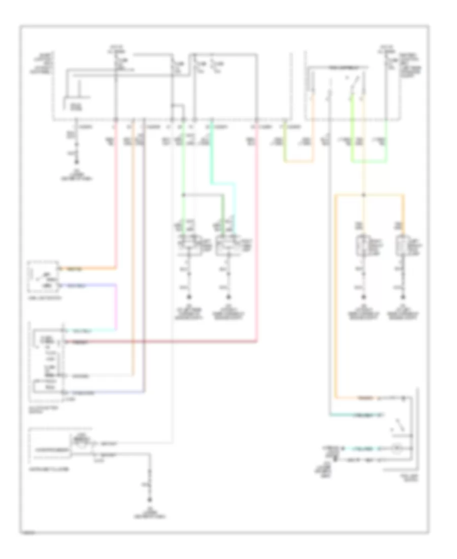
Instrument Illumination Wiring Diagram for Mazda BSE 2004 4000
 https://portal-diagnostov.com/license.html
Automotive Electricians Portal FZCO
Automotive Electricians Portal FZCO
https://portal-diagnostov.com/license.html
https://portal-diagnostov.com/license.html
Automotive Electricians Portal FZCO
Automotive Electricians Portal FZCOList of elements for Instrument Illumination Wiring Diagram for Mazda BSE 2004 4000:
- Air bag sliding contact (on steering column)
- Audio unit
- C215
- Courtesy lamps circuit
- Dimming
- Fog lamp switch
- Four- wheel drive switch
- Front function selector switch assembly
- Fuse
- Fuse 20a
- G10 (under driver's seat)
- G8 (under center of dash)
- Ground, steering wheel assembly
- Head
- Hot at all times
- Hot in start or run
- Illumination
- Illumination (6 bulbs)
- Instrument cluster
- Instrument panel dimming module
- Interior
- Main light switch
- Micro- processor
- Nca
- Off
- Park
- Park lamp relay
- Smart junction box (sjb) (at right kick panel)
- Solid state
- Speed control on/off switch
- Speed control set/ resume switch
- Switch
- X-2280c
- X-2280d
POWER DISTRIBUTION
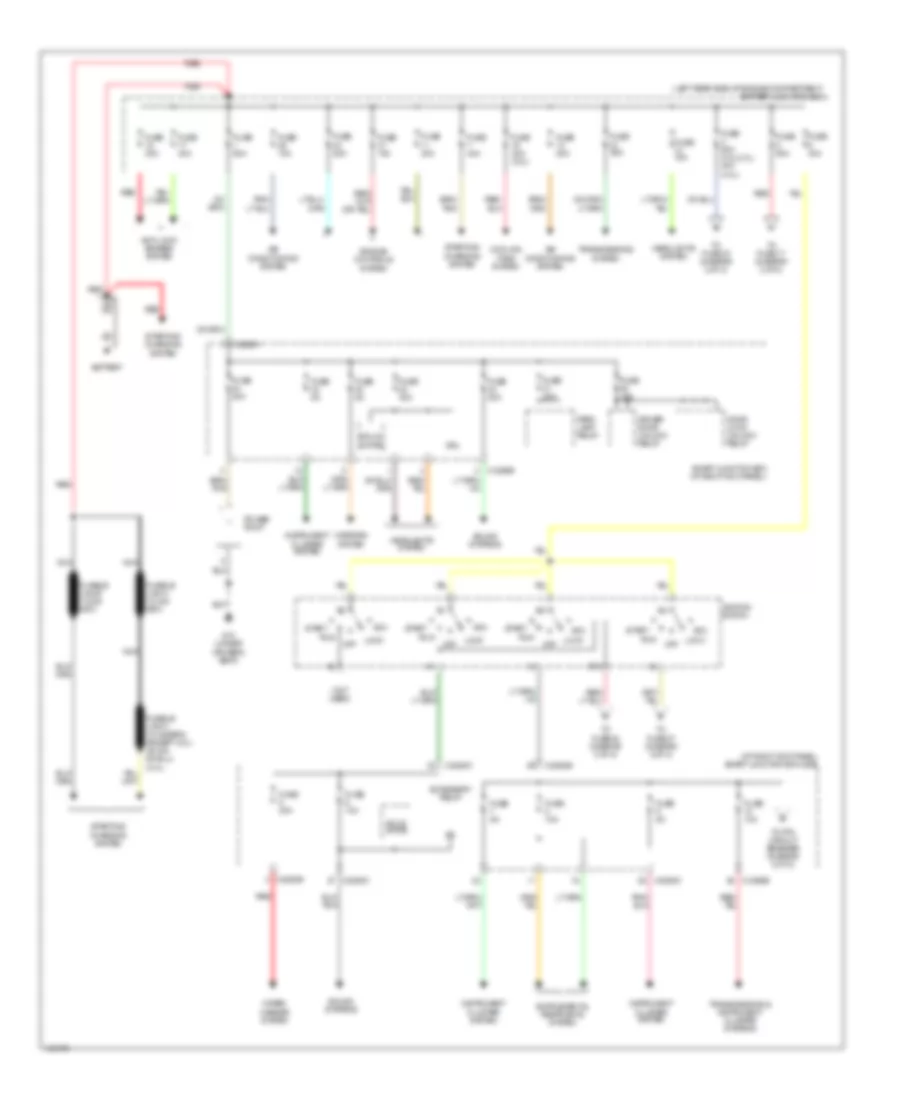
Power Distribution Wiring Diagram (1 of 2) for Mazda BSE 2004 4000
 https://portal-diagnostov.com/license.html
Automotive Electricians Portal FZCO
Automotive Electricians Portal FZCO
https://portal-diagnostov.com/license.html
https://portal-diagnostov.com/license.html
Automotive Electricians Portal FZCO
Automotive Electricians Portal FZCOList of elements for Power Distribution Wiring Diagram (1 of 2) for Mazda BSE 2004 4000:
- (at right kick panel) smart junction box (sjb)
- (left rear side of engine compartment) battery junction box
- (not used)
- Acc
- Accessory relay
- Air conditioning system
- Anti-lock brakes system
- Battery
- C2280a
- Cooling fans system
- Door lock/ unlock relay
- Driver door unlock relay
- Driver's seat)
- Drl
- Engine controls system
- Fuse 10a
- Fuse 15a
- Fuse 20a
- Fuse 20a (2.3l)
- Fuse 30a
- Fuse 40a
- Fuse 50a
- Fuse 50a (3.0l,2.3l) 40a (4.0l)
- Fuse 5a
- G10 (under
- Headlights system
- Ignition switch
- Instrument cluster system
- Lock
- Mirrors system
- Nca
- Off
- Park lamp relay
- Power point
- Red
- Run
- Smart junction box (at right kick panel)
- Solid state
- Sound systems
- Sta
- Start
- Starting/ charging system
- To fuse 17 (diagram 2 of 2)
- To fuse 22 (diagram 2 of 2)
- To fuse 27 (diagram 2 of 2)
- To fuse 33 (diagram 2 of 2)
- To ptc circuit breaker (diagram 2 of 2)
- Transmissions & instrument cluster systems
- Transmissions system
- Wiper/ washer system
- X-2280b
- X-2280c
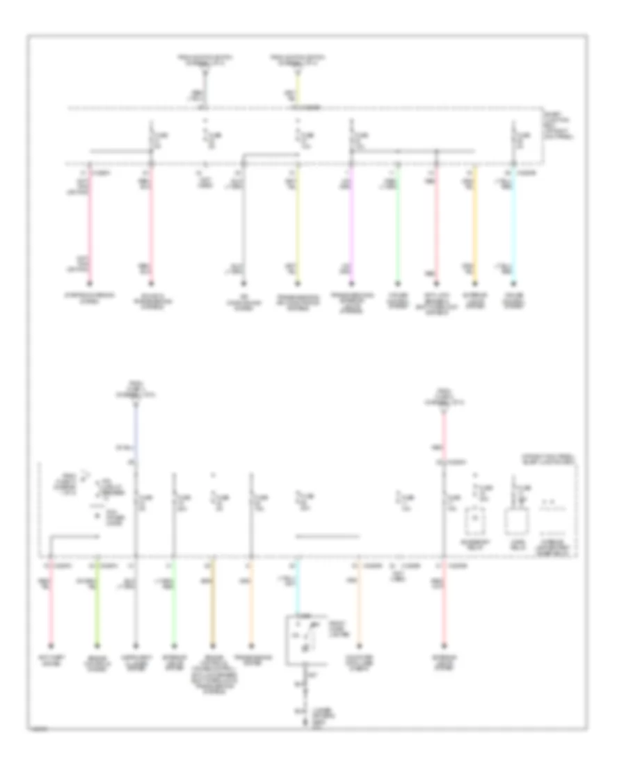
Power Distribution Wiring Diagram (2 of 2) for Mazda BSE 2004 4000
 https://portal-diagnostov.com/license.html
Automotive Electricians Portal FZCO
Automotive Electricians Portal FZCO
https://portal-diagnostov.com/license.html
https://portal-diagnostov.com/license.html
Automotive Electricians Portal FZCO
Automotive Electricians Portal FZCOList of elements for Power Distribution Wiring Diagram (2 of 2) for Mazda BSE 2004 4000:
- (at right kick panel) smart junction box
- (not used)
- (under driver's seat) g10
- Accessory relay
- Air conditioning system
- Anti-lock brakes & shift interlock systems
- Anti-theft system
- Computer data lines sysetm
- Cruise control system
- Engine controls system
- Engine controls, cruise control, anti-lock brakes, shift interlock & transmissions systems
- Exterior lights system
- From fuse 3 (diagram 1 of 2)
- From fuse 5 (diagram 1 of 2)
- From fuse 10 (diagram 1 of 2)
- From ignition switch (diagram 1 of 2)
- Front cigar lighter
- Fuse 10a
- Fuse 15a
- Fuse 20a
- Fuse 2a
- Fuse 30a
- Fuse 5a
- Horn relay
- I226
- I227
- Instrument cluster system
- Interior lamp/battery saver relay
- Off
- Pcm power diode
- Ptc circuit breaker 1a
- Red
- Smart junction box (at right kick panel)
- Sound & transmissions systems
- Starting/charging system
- Transmissions & air conditioning systems
- Transmissions & exterior lights systems
- Transmissions system
- X-2280a
- X-2280b
- X-2280c
- X-2280d
POWER MIRRORS
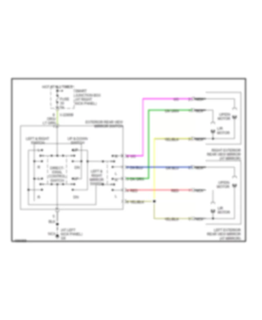
Power Mirrors Wiring Diagram for Mazda BSE 2004 4000
 https://portal-diagnostov.com/license.html
Automotive Electricians Portal FZCO
Automotive Electricians Portal FZCO
https://portal-diagnostov.com/license.html
https://portal-diagnostov.com/license.html
Automotive Electricians Portal FZCO
Automotive Electricians Portal FZCOList of elements for Power Mirrors Wiring Diagram for Mazda BSE 2004 4000:
- (at left kick panel) g9
- Direct- ional control switch
- Exterior rear view mirror switch
- Fuse 5a
- Hot at all times
- L/r motor
- Left & right mirror switch
- Left & right switch
- Left exterior rear view mirror (at mirror)
- Nca
- Red
- Right exterior rear view mirror (at mirror)
- Smart junction box (at right kick panel)
- Up & down switch
- Up/dn motor
- X-2280b
POWER WINDOWS
Power Windows Wiring Diagram for Mazda BSE 2004 4000
 https://portal-diagnostov.com/license.html
Automotive Electricians Portal FZCO
Automotive Electricians Portal FZCO
https://portal-diagnostov.com/license.html
https://portal-diagnostov.com/license.html
Automotive Electricians Portal FZCO
Automotive Electricians Portal FZCOList of elements for Power Windows Wiring Diagram for Mazda BSE 2004 4000:
- (in left front door) driver side front power window motor
- (in right front door)
- 11a
- Accessory relay
- Down
- Driver power window switch
- Fuse 10a
- Fuse 30a
- G10 (at left front of vehicle floor)
- G8 (under front of center console)
- G9 (at left kick panel)
- Hot at all times
- Hot in on or acc
- Left
- Low current board
- Nca
- Off
- One-touch window relay
- Passenger side front power window motor
- Passenger side front power window switch
- Ptc circuit breaker
- Red
- Resistor
- Rest
- Right
- Smart junction box (sjb) (at right kick panel)
- X-2280c
- X-2280d
RADIO
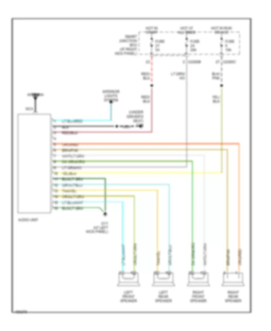
Radio Wiring Diagram for Mazda BSE 2004 4000
 https://portal-diagnostov.com/license.html
Automotive Electricians Portal FZCO
Automotive Electricians Portal FZCO
https://portal-diagnostov.com/license.html
https://portal-diagnostov.com/license.html
Automotive Electricians Portal FZCO
Automotive Electricians Portal FZCOList of elements for Radio Wiring Diagram for Mazda BSE 2004 4000:
- (under driver's seat) g10
- Antenna
- Audio unit
- Fuse 10a
- Fuse 20a
- Fuse 5a
- G11 (at left kick panel)
- Hot at all times
- Hot in run or acc
- Hot in start
- Interior lights system
- Left front speaker
- Left rear speaker
- Nca
- Right front speaker
- Right rear speaker
- Smart junction box (at right kick panel)
- X2280b
- X2280c
SHIFT INTERLOCK
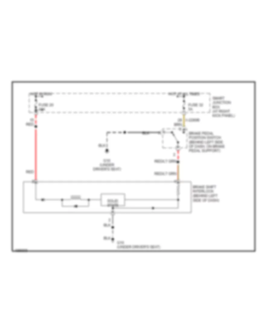
Shift Interlock Wiring Diagram for Mazda BSE 2004 4000
 https://portal-diagnostov.com/license.html
Automotive Electricians Portal FZCO
Automotive Electricians Portal FZCO
https://portal-diagnostov.com/license.html
https://portal-diagnostov.com/license.html
Automotive Electricians Portal FZCO
Automotive Electricians Portal FZCOList of elements for Shift Interlock Wiring Diagram for Mazda BSE 2004 4000:
- Brake pedal position switch (behind left side of dash, on brake pedal support)
- Brake shift interlock (behind left side of dash)
- Fuse 20 10a
- Fuse 32 5a
- G10 (under driver's seat)
- Hot at all times
- Hot in run
- Red
- Smart junction box (at right kick panel)
- Solid state
- X-2280b
STARTING/CHARGING
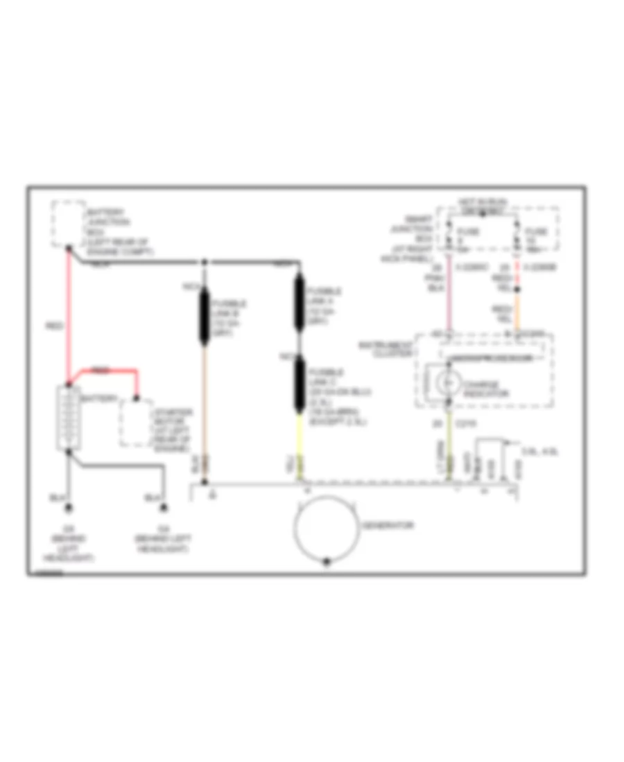
Charging Wiring Diagram for Mazda BSE 2004 4000
 https://portal-diagnostov.com/license.html
Automotive Electricians Portal FZCO
Automotive Electricians Portal FZCO
https://portal-diagnostov.com/license.html
https://portal-diagnostov.com/license.html
Automotive Electricians Portal FZCO
Automotive Electricians Portal FZCOList of elements for Charging Wiring Diagram for Mazda BSE 2004 4000:
- 3.0l, 4.0l
- A168
- A169
- Battery
- Battery junction box (left rear of engine compt)
- C215
- C216
- Charge indicator
- Fuse 10a
- Fuse 5a
- G4 (behind left headlight)
- G6 (behind left headlight)
- Generator
- Hot in run or start
- Instrument cluster
- Microprocessor
- Nca
- Red
- Smart junction box (at right kick panel)
- Starter motor (at left rear of engine)
- X-2280b
- X-2280c
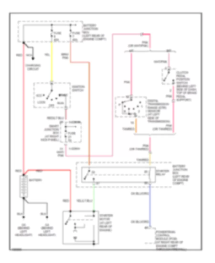
Starting Wiring Diagram for Mazda BSE 2004 4000
 https://portal-diagnostov.com/license.html
Automotive Electricians Portal FZCO
Automotive Electricians Portal FZCO
https://portal-diagnostov.com/license.html
https://portal-diagnostov.com/license.html
Automotive Electricians Portal FZCO
Automotive Electricians Portal FZCOList of elements for Starting Wiring Diagram for Mazda BSE 2004 4000:
- A/t
- Acc
- Battery
- Battery junction box (left rear of engine compt)
- Charging circuit
- Clutch pedal position switch (behind left side of dash, top of brake pedal support)
- Digital transmission range (dtr) sensor (at left side of transmission)
- Fuse 40a
- Fuse 5a
- G4 (behind left headlight)
- G6 (behind left headlight)
- Ignition switch
- Lock
- M/t
- Nca
- Off
- Pnk
- Pnk (or tan/red)
- Powertrain control module (pcm) (at right rear of engine compt through firewall)
- Red
- Run
- Smart junction box (at right kick panel)
- Start
- Starter motor (at left rear of engine)
- Starter relay
- Tan/red
- X-2280a
- X-2280b
SUPPLEMENTAL RESTRAINTS
Supplemental Restraints Wiring Diagram for Mazda BSE 2004 4000
 https://portal-diagnostov.com/license.html
Automotive Electricians Portal FZCO
Automotive Electricians Portal FZCO
https://portal-diagnostov.com/license.html
https://portal-diagnostov.com/license.html
Automotive Electricians Portal FZCO
Automotive Electricians Portal FZCOList of elements for Supplemental Restraints Wiring Diagram for Mazda BSE 2004 4000:
- (under center of dash) g8
- (under driver's seat)
- 1 ohm
- A-168
- Air bag
- Air bag sliding contact
- C-215
- C-216
- Data link connector (dlc) (partial) (fastened to bottom of dash, near steering column)
- Driver air bag module
- Driver safety belt retractor pretensioner
- Fuse 10 10a
- Fuse 8 10a
- G10
- Generator
- Hot in run or start
- Instrument cluster
- Nca
- Note: shorting bar connectors are used on restraint control module harness connector when module is disconnected between pins 3 & 4, 6 & 7, 20 & 21
- Off
- Ohm
- Ohms
- Passenger air bag deactivation (pad) switch
- Passenger air bag module
- Passenger safety belt retractor pretensioner
- Restraint control module (behind center of dash)
- Safety belt
- Shorting bar
- Smart junction box (right kick panel)
- Tone
- X-2280b
- X-2280c
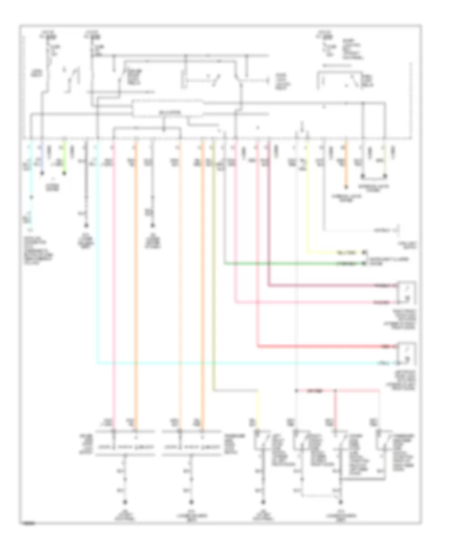
TRANSMISSION
4WD Wiring Diagram for Mazda BSE 2004 4000
 https://portal-diagnostov.com/license.html
Automotive Electricians Portal FZCO
Automotive Electricians Portal FZCO
https://portal-diagnostov.com/license.html
https://portal-diagnostov.com/license.html
Automotive Electricians Portal FZCO
Automotive Electricians Portal FZCOList of elements for 4WD Wiring Diagram for Mazda BSE 2004 4000:
- (at left side of transmission) digital transmission range sensor
- (under driver's seat) g10
- 4wd hi ind
- 4wd lo ind
- 4wd switch
- A/t
- B111
- Battery junction box (left rear side of engine compt)
- Bpp switch
- Brake pedal position switch (behind left side of dash, on brake pedal support)
- C215
- C281a
- C281b
- Cruise control system
- Data link connector (fastened to bottom of dash, near steering column)
- Driver's seat)
- Four-wheel drive control module (behind center of dash)
- Four-wheel drive switch
- Fuse 10a
- Fuse 15a
- Fuse 20a
- Fuse 5a
- G10 (under
- G2 (at center rear of engine compt)
- G8 (under center of dash)
- Ground
- Head
- Hot at all times
- Hot in run
- Hot in run or start
- Hot in start
- Ign (run)
- Ign (st/run)
- Illum
- Instrument cluster
- Interior lights system
- Iso bus
- M/t
- Main light switch
- Microprocessor
- Motor 1
- Motor 2
- Motor 3
- Motor 4
- Motor 5
- Nca
- Neutral sens
- Off
- Park
- Powertrain control module (at right rear of engine compt, through firewall)
- Sig return
- Smart junction box (at right kick panel)
- Transfer case
- Transfer case shift motor assembly (on transfer case)
- Vss input
- X-2280b
- X-2280c
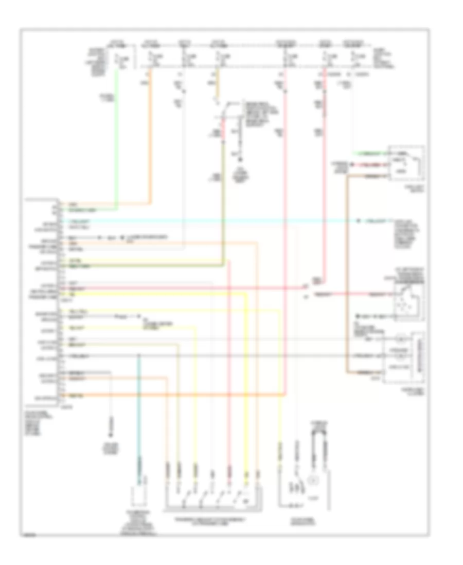
A/T Wiring Diagram (1 of 2) for Mazda BSE 2004 4000
 https://portal-diagnostov.com/license.html
Automotive Electricians Portal FZCO
Automotive Electricians Portal FZCO
https://portal-diagnostov.com/license.html
https://portal-diagnostov.com/license.html
Automotive Electricians Portal FZCO
Automotive Electricians Portal FZCOList of elements for A/T Wiring Diagram (1 of 2) for Mazda BSE 2004 4000:
- (fastened to bottom of dash, near steering column)
- 5r55e transmission
- Battery junction box (left rear of engine compt)
- Brake pedal position switch (behind left side of dash, on brake pedal support)
- C215
- C216
- C216 o/d off ind
- Check engine ind
- Data link connector
- Electronic pressure control (epc) solenoid
- Engine controls system
- Fuse 10a
- Fuse 15a
- Fuse 30a
- Fuse 5a
- G1 (behind left headlight)
- G10 (under driver's seat)
- Hot at all times
- Hot in on
- Hot in on or start
- Instrument cluster
- Intermediate shaft speed (iss) sensor (at left side of transmission)
- Microprocessor
- Nca
- Output shaft speed (oss) sensor (at left rear of transmission)
- Pcm power diode
- Powertrain control module (pcm) (at right rear of engine compartment, through firewall)
- Prndl
- Ptc 1a
- Red
- Shift solenoids
- Smart junction box (at right kick panel)
- Torque converter clutch (tcc) solenoid
- Transmission control switch (on end of transmission selector lever)
- Transmission fluid temperature (tft) sensor
- Turbine shaft speed (tss) sensor
- X-2280a
- X-2280b
A/T Wiring Diagram (2 of 2) for Mazda BSE 2004 4000
 https://portal-diagnostov.com/license.html
Automotive Electricians Portal FZCO
Automotive Electricians Portal FZCO
https://portal-diagnostov.com/license.html
https://portal-diagnostov.com/license.html
Automotive Electricians Portal FZCO
Automotive Electricians Portal FZCOList of elements for A/T Wiring Diagram (2 of 2) for Mazda BSE 2004 4000:
- (at left side of transmission) digital transmission range sensor
- Battery junction box (left rear of engine compt)
- Engine controls system
- Engine coolant temperature (ect) sensor (on top front center of engine)
- G1 (behind left headlight)
- Pcm power relay
- R p
- Red
- Throttle position (tp) sensor (on throttle body assembly)
WARNING SYSTEMS
Warning Systems Wiring Diagram for Mazda BSE 2004 4000
 https://portal-diagnostov.com/license.html
Automotive Electricians Portal FZCO
Automotive Electricians Portal FZCO
https://portal-diagnostov.com/license.html
https://portal-diagnostov.com/license.html
Automotive Electricians Portal FZCO
Automotive Electricians Portal FZCOList of elements for Warning Systems Wiring Diagram for Mazda BSE 2004 4000:
- C215
- C216
- Can+
- Can-
- Computer data lines system
- Door ajar ind
- Driver safety belt retractor pretensioner
- Fuse 10a
- Fuse 5a
- G10 (under driver's seat)
- G8 (under center of dash)
- G9 (at left kick panel)
- Ground
- Head
- Hot at all times
- Hot in start or run
- Ignition key switch
- Instrument cluster
- Interior lights system
- Left front door ajar switch (at rear of left front door)
- Main light switch
- Microprocessor
- N219
- Nca
- Off
- Park
- Restraint control module (below center of dash)
- Safety belt ind
- Smart junction box (sjb) (at right kick panel)
- Solid state
- Sw in
- Tone sig
- Vbatt
- Vpwr
- Warning chime
- X-2280b
- X-2280c
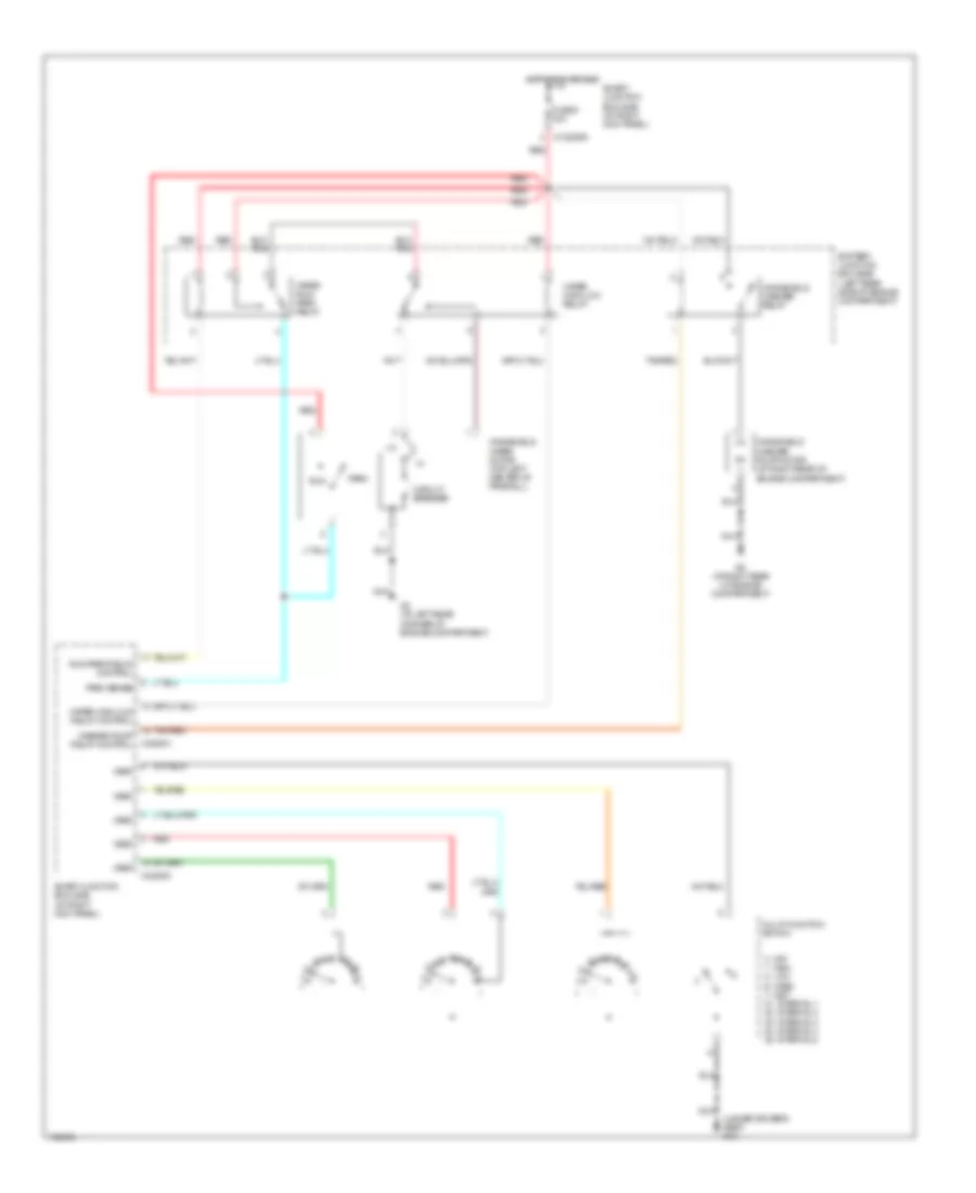
WIPER/WASHER
Wiper/Washer Wiring Diagram for Mazda BSE 2004 4000
 https://portal-diagnostov.com/license.html
Automotive Electricians Portal FZCO
Automotive Electricians Portal FZCO
https://portal-diagnostov.com/license.html
https://portal-diagnostov.com/license.html
Automotive Electricians Portal FZCO
Automotive Electricians Portal FZCOList of elements for Wiper/Washer Wiring Diagram for Mazda BSE 2004 4000:
- (under driver's seat) g10
- 0. off 1. high 2. low 6. wash 7. mist 21. interval 1 22. interval 2 23. interval 3 24. interval 4 25. interval 5
- Battery junction box (bjb) (left rear side of engine compartment)
- Circuit breaker
- Fuse 5 30a
- G3 (at left rear corner of engine compartment)
- G5 (at right rear of engine compartment)
- Hot in run or acc
- Multi-function switch
- Nca
- Park
- Park sense
- Red
- Run
- Run/park relay control
- Smart junction box (sjb) (at right kick panel)
- Tan/red
- Vref
- Washer pump relay control
- Windshield washer pump motor (at right rear of engine compartment)
- Windshield washer relay
- Windshield wiper motor (top left center of firewall)
- Wiper high/low relay
- Wiper high/low relay control
- Wiper run/ park relay
- X-2280a
- X-2280d
- X-c2280a

 Čeština
 Dansk
Dansk Deutsch
 Ελληνικά
 English
 English
 Español
 Suomi
Suomi Français
 Français
 עברית
עברית Hrvatski
 Magyar
 Italiano
 日本語
日本語 Nederlands
 Polski
 Português
 Português
 Română
 Русский
 Slovenčina
 Slovenščina
 Svenska
 Türkçe
 中文 (中国)
