AIR CONDITIONING
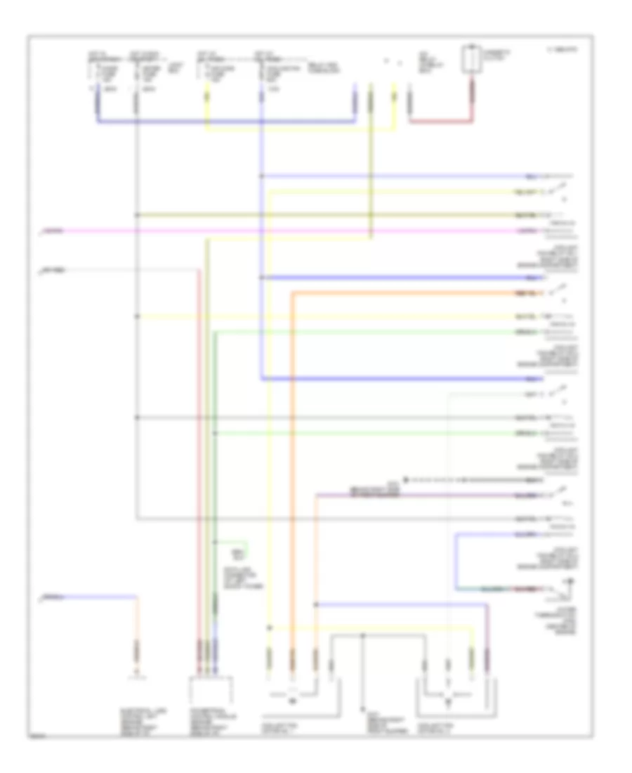
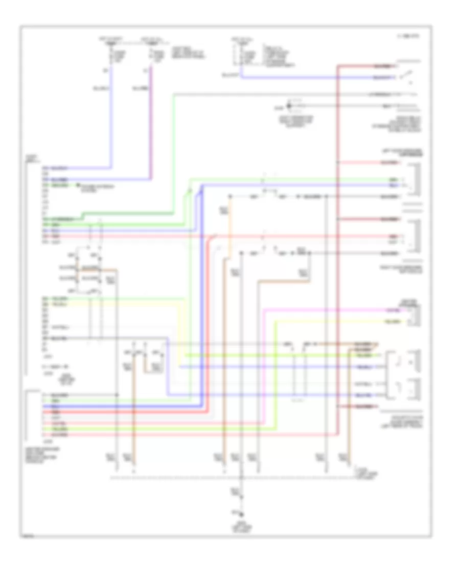
A/C Wiring Diagram (1 of 2) for Mazda RX-7 1994
 https://portal-diagnostov.com/license.html
Automotive Electricians Portal FZCO
Automotive Electricians Portal FZCO
https://portal-diagnostov.com/license.html
https://portal-diagnostov.com/license.html
Automotive Electricians Portal FZCO
Automotive Electricians Portal FZCO
List of elements for A/C Wiring Diagram (1 of 2) for Mazda RX-7 1994:
- (amplifier)
- (behind center
- (behind center of i/p)
- (left kick panel)
- (right kick panel)
- Air conditioning sensor
- Air intake actuator (behind right of i/p)
- Air mix actuator (behind center of i/p)
- Airflow mode actuator (behind center of i/p)
- B/l
- B2 fuse 40a
- Blower motor
- Blower relay (behind right side of i/p)
- C 1995 vftc
- Cold
- Com
- Def
- G200 or g203
- G206
- G206 (behind center of i/p)
- H/d
- Heat
- Heater control unit
- Heater control unit (controller)
- Heater control unit (fan switch)
- Hot
- Hot at all times
- Hot in run or start
- Jb-02
- Jb-07
- Joint box
- Main fuse box
- Nca
- Of i/p)
- Off
- Rear wiper fuse 10a
- Red
- Refrigerant pressure switch (left front of engine compartment)
- Resistor (behind right side of i/p)
- Thermoswitch (behind right side of i/p)
- Transmission controls system
- Vent
- X-08
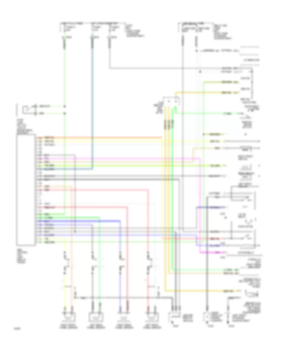
A/C Wiring Diagram (2 of 2) for Mazda RX-7 1994
 https://portal-diagnostov.com/license.html
Automotive Electricians Portal FZCO
Automotive Electricians Portal FZCO
https://portal-diagnostov.com/license.html
https://portal-diagnostov.com/license.html
Automotive Electricians Portal FZCO
Automotive Electricians Portal FZCOList of elements for A/C Wiring Diagram (2 of 2) for Mazda RX-7 1994:
- A/c relay (in relay box)
- Air cond fuse 15a
- C 1995 vftc
- Cigar fuse 15a
- Coolant fan motor no. 1
- Coolant fan motor no. 2
- Coolant fan relay no.1 (right side of engine compartment)
- Coolant fan relay no.2 (right side of engine compartment)
- Coolant fan relay no.3 (right side of engine compartment)
- Coolant fan relay no.4 (right side of engine compartment)
- Cooling fan fuse 60a
- Data link connector (at left shock tower)
- Electrical load control unit (engine) (behind right side of i/p)
- G101 (behind right side of front bumper)
- Hot at all times
- Hot in acc or run
- Hot in run or start
- Jb-03
- Jb-04
- Joint box
- Magnetic clutch
- Meter fuse 15a
- Powertrain control module (engine) (behind right side of i/p)
- Relay and fuse block
- Water thermoswitch (fan) (center of engine)
- X-02
ANTI-LOCK BRAKES
Anti-lock Brake Wiring Diagrams for Mazda RX-7 1994
 https://portal-diagnostov.com/license.html
Automotive Electricians Portal FZCO
Automotive Electricians Portal FZCO
https://portal-diagnostov.com/license.html
https://portal-diagnostov.com/license.html
Automotive Electricians Portal FZCO
Automotive Electricians Portal FZCOList of elements for Anti-lock Brake Wiring Diagrams for Mazda RX-7 1994:
- (canada only) drl control unit (left kick panel)
- (center rear of vehicle)
- (left front of engine compartment)
- (right front of engine compart)
- (right side of engine compartment)
- (top of brake pedal support)
- 1d
- Abs control unit (left side of trunk)
- Abs fuse 15a
- Abs fuse 60a
- Abs ind
- Alternator
- Brake fluid level switch (left rear of engine compartment)
- Brk ind
- Chg ind
- Fuse 1 10a
- Fuse 10 20a
- Fuse 9 15a
- G108
- G109
- G407
- Hot at all times
- Hot in run and start
- Hydraulic unit (right rear eng comp)
- Indicators
- Instrument cluster
- Joint box
- Left front abs sol
- Left front wheel sensor
- Left rear wheel sensor
- Motor relay
- O-02
- O-03
- Parking brake switch
- Pump motor
- Rear abs sol
- Red
- Relay and fuse box
- Right front abs sol
- Right front wheel sensor
- Right rear wheel sensor
- Stop lamp switch
- Valve relay
- X-06 (behind left side of i/p)
ANTI-THEFT
Anti-theft Wiring Diagram for Mazda RX-7 1994
 https://portal-diagnostov.com/license.html
Automotive Electricians Portal FZCO
Automotive Electricians Portal FZCO
https://portal-diagnostov.com/license.html
https://portal-diagnostov.com/license.html
Automotive Electricians Portal FZCO
Automotive Electricians Portal FZCOList of elements for Anti-theft Wiring Diagram for Mazda RX-7 1994:
- 1995 vftc c
- Central processing unit no. 1
- Central processing unit no. 2 (left side of i/p)
- Cigar fuse 15a
- Door lock timer unit (left kick panel)
- Exterior light system
- Exterior lights system (hazard warning switch)
- Flasher unit (in cpu no.2)
- Front left park/marker lights
- Front right park/marker lights
- G107 (behind right headlight)
- G200 (left kick panel)
- G201 (right side of i/p)
- G202 (left side of i/p)
- G407 (center rear of trunk)
- Headlight relay (left side of engine compartment)
- Headlight system (light switch)
- Hood switch
- Horn relay (relay box) (center front of engine compartment)
- Hot at all times
- Hot in run and acc
- Hot in run and start
- Joint box (left side of i/p)
- Left door key cylinder switch
- Left door lock switch
- Left door switch
- Left horn
- Meter fuse 15a
- Outer door handle switch
- Rear hatch key cylinder switch
- Rear marker/taillights lights
- Right door key cylinder switch
- Right door lock switch
- Right door switch
- Right horn
- Room fuse 10a
- Security light
- Starter cut relay (left kick panel)
BODY COMPUTER
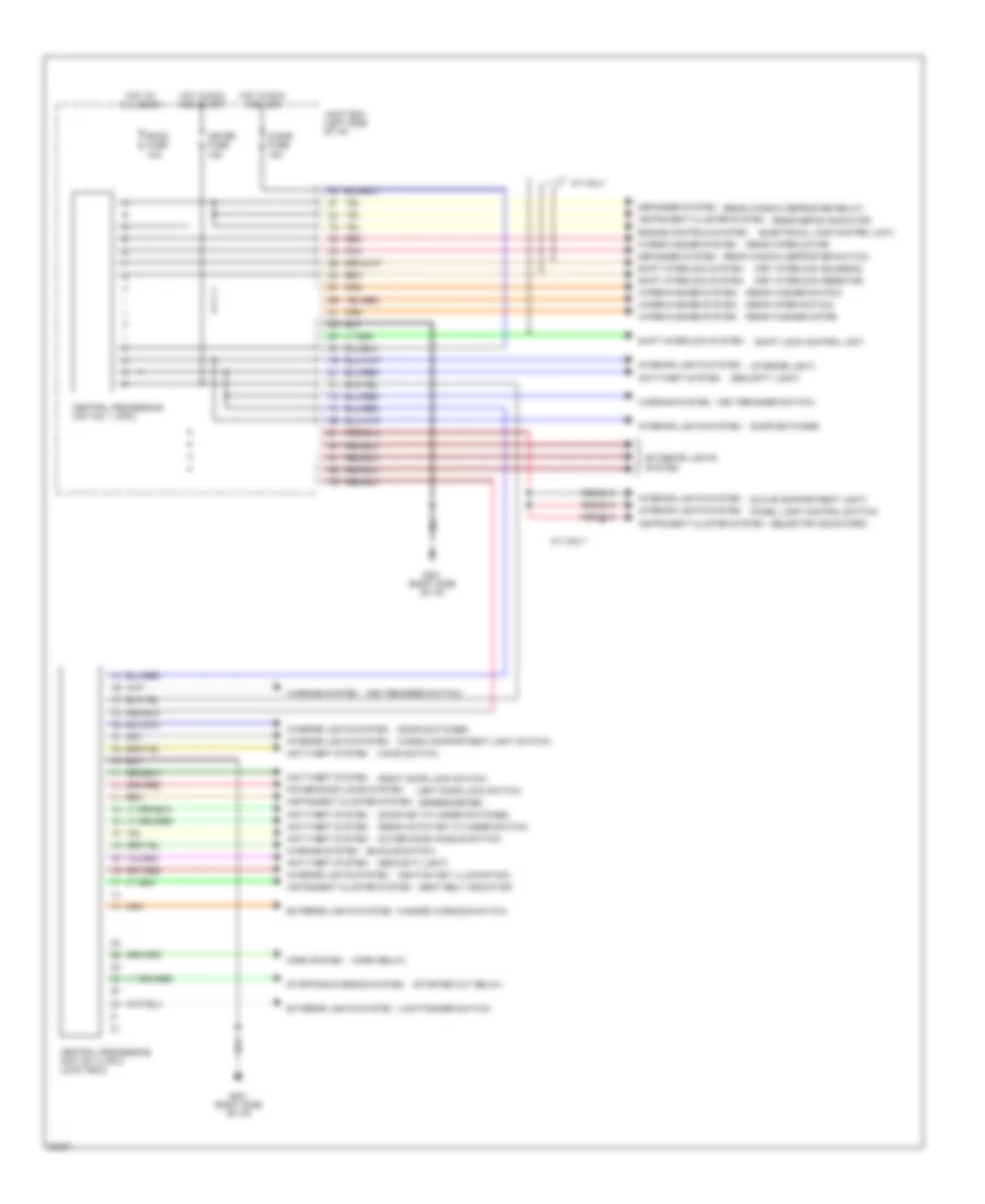
Central Processing Unit Wiring Diagram for Mazda RX-7 1994
 https://portal-diagnostov.com/license.html
Automotive Electricians Portal FZCO
Automotive Electricians Portal FZCO
https://portal-diagnostov.com/license.html
https://portal-diagnostov.com/license.html
Automotive Electricians Portal FZCO
Automotive Electricians Portal FZCOList of elements for Central Processing Unit Wiring Diagram for Mazda RX-7 1994:
- (buckle switch)
- (cargo compartment light switch)
- (door key cylinder switches)
- (door switches)
- (electrical load control unit)
- (glove compartment light)
- (hazard warning switch)
- (hood switch)
- (horn relay)
- (ignition key illumination)
- (interior light)
- (key interlock resistor)
- (key interlock solenoid)
- (key reminder switch)
- (left door lock switch)
- (light/dimmer switch)
- (outer door handle switch)
- (panel light control switch)
- (rear defog indicator)
- (rear hatch key cylinder switch)
- (rear washer motor)
- (rear washer switch)
- (rear window defroster relay)
- (rear window defroster switch)
- (rear wiper motor)
- (rear wiper switch)
- (right door lock switch)
- (seat belt indicator)
- (security light)
- (selector indicators)
- (shift lock control unit)
- (speedometer)
- (starter cut relay)
- A/t only
- Anti-theft system
- Central processing unit no. 1 (cpu)
- Central processing unit no. 2 (cpu) (joint box)
- Cigar fuse 15a
- Defogger system
- Engine controls system
- Exterior lights system
- G201 (right side of i/p)
- Horn system
- Hot at all times
- Hot in run and acc
- Hot in run and start
- Instrument cluster system
- Interior lights system
- Joint box (left side of i/p)
- Meter fuse 15a
- Pnk
- Power door locks system
- Red
- Room fuse 10a
- Shift interlock system
- Starting/charging system
- Warning system
- Wiper/washer system
COMPUTER DATA LINES
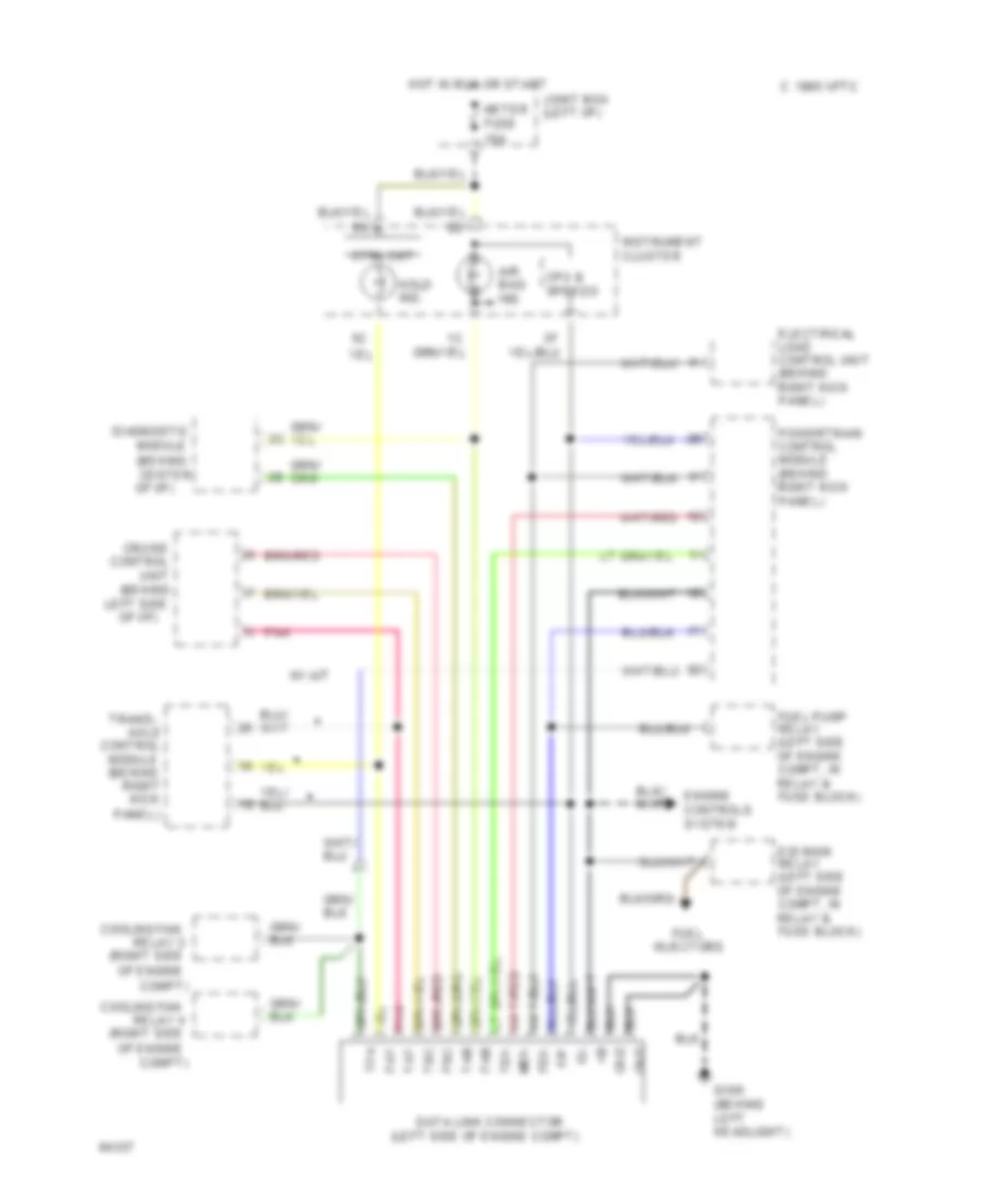
Data Link Connector Wiring Diagram for Mazda RX-7 1994
 https://portal-diagnostov.com/license.html
Automotive Electricians Portal FZCO
Automotive Electricians Portal FZCO
https://portal-diagnostov.com/license.html
https://portal-diagnostov.com/license.html
Automotive Electricians Portal FZCO
Automotive Electricians Portal FZCOList of elements for Data Link Connector Wiring Diagram for Mazda RX-7 1994:
- (behind
- (behind center of i/p)
- (left side of engine compt)
- (right side
- 1995 vftc c
- Air bag ind.
- Axle
- Compt)
- Control
- Cooling fan
- Cpu & speedo
- Cruise
- Ctrl ckt
- Data link connector
- Diagnostic
- Egi main relay (left side of engine compt, in relay & fuse block)
- Electrical load control unit (behind right kick panel)
- Engine controls system
- F/p
- Fab
- Fat
- Fen
- Fsc
- Fuel
- Fuel pump relay (left side of engine compt, in relay & fuse block)
- G106 (behind left headlight)
- Gnd
- Hold ind.
- Hot in run or start
- Ig-
- Injectors
- Instrument cluster
- Joint box (left i/p)
- L pnk
- Left side
- Men
- Meter fuse 15a
- Module
- Module (behind
- Of engine
- Of i/p)
- Panel)
- Pnk
- Powertrain control module (behind right kick panel)
- Relay 2
- Relay 4
- Right kick
- Tab
- Tat
- Ten
- Tfa
- Trans-
- Tsc
- Unit
- W/ a/t
COOLING FAN
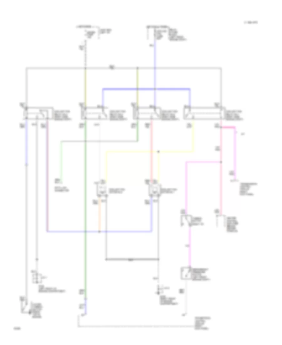
Cooling Fan Wiring Diagram for Mazda RX-7 1994
 https://portal-diagnostov.com/license.html
Automotive Electricians Portal FZCO
Automotive Electricians Portal FZCO
https://portal-diagnostov.com/license.html
https://portal-diagnostov.com/license.html
Automotive Electricians Portal FZCO
Automotive Electricians Portal FZCOList of elements for Cooling Fan Wiring Diagram for Mazda RX-7 1994:
- (right i/p)
- 1994 vftc c
- A/t
- Coolant fan motor n0.1
- Coolant fan motor n0.2
- Coolant fan relay no.1 (right side engine compt)
- Coolant fan relay no.2 (right side engine compt)
- Coolant fan relay no.3 (right side engine compt)
- Coolant fan relay no.4 (right side engine compt)
- Cooling fan fuse 60a
- Data link connector
- G108 (left front of engine compartment)
- G109 (right front of engine compartment)
- Heater control amplifier (behind center console)
- Hot at all times
- Hot in run
- J/c 1
- J/c 2
- Joint box (left i/p)
- Meter fuse 15a
- Powertrain control module (right kick panel)
- Refrigerant pressure switch (left front engine compt)
- Relay & fuse block (left front engine compt)
- Thermo- switch
- Transmission control module (right kick panel)
- Water thermo- switch (front top of engine)
CRUISE CONTROL
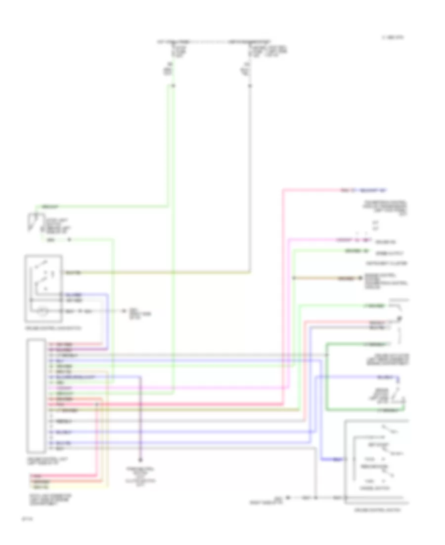
Cruise Control Wiring Diagram for Mazda RX-7 1994
 https://portal-diagnostov.com/license.html
Automotive Electricians Portal FZCO
Automotive Electricians Portal FZCO
https://portal-diagnostov.com/license.html
https://portal-diagnostov.com/license.html
Automotive Electricians Portal FZCO
Automotive Electricians Portal FZCOList of elements for Cruise Control Wiring Diagram for Mazda RX-7 1994:
- 1995 vftc c
- A/t
- Brake switch (left side of i/p)
- Cancel switch
- Cruise actuator (left rear corner of engine compartment)
- Cruise control main switch
- Cruise control switch
- Cruise control unit (left side of i/p)
- Cruise ind
- Data link connector (left side of engine compartment)
- Engine control system (powertrain control module)
- G201 (right side of i/p)
- Hot at all times
- Hot in run and start
- Instrument cluster
- Joint box (left side of i/p)
- M/t
- Meter fuse 15a
- Park/neutral switch (a/t) clutch switch (m/t)
- Pnk
- Powertrain control module (transmission) (left kick panel) (a/t)
- Resume/accel
- Set/coast
- Speed output
- Stop fuse 20a
- Stop light switch (behind left side of i/p)
DEFOGGERS
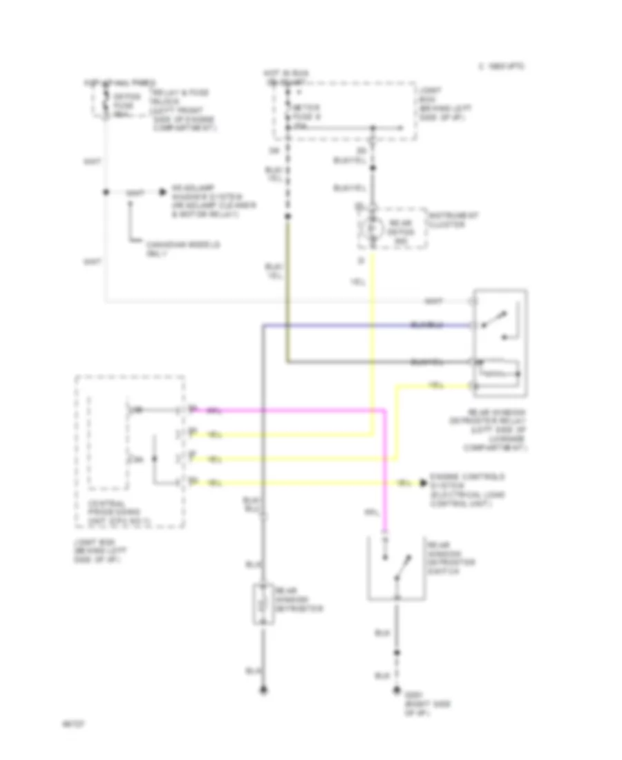
Defogger Wiring Diagram for Mazda RX-7 1994
 https://portal-diagnostov.com/license.html
Automotive Electricians Portal FZCO
Automotive Electricians Portal FZCO
https://portal-diagnostov.com/license.html
https://portal-diagnostov.com/license.html
Automotive Electricians Portal FZCO
Automotive Electricians Portal FZCOList of elements for Defogger Wiring Diagram for Mazda RX-7 1994:
- C 1995 vftc
- Canadian models only
- Central processing unit (cpu no.1)
- Defog fuse 60a
- Engine controls system (electrical load control unit)
- G201 (right side of i/p)
- Headlamp washer system (headlamp cleaner & motor relay)
- Hot at all times
- Hot in run or start
- Instrument cluster
- Joint box (behind left side of i/p)
- Joint box (behind left side of i/p)
- Meter fuse 9 15a
- Rear defog ind
- Rear window defroster
- Rear window defroster relay (left side of luggage compartment)
- Rear window defroster switch
- Relay & fuse block (left front side of engine compartment)
ENGINE PERFORMANCE
1.3L
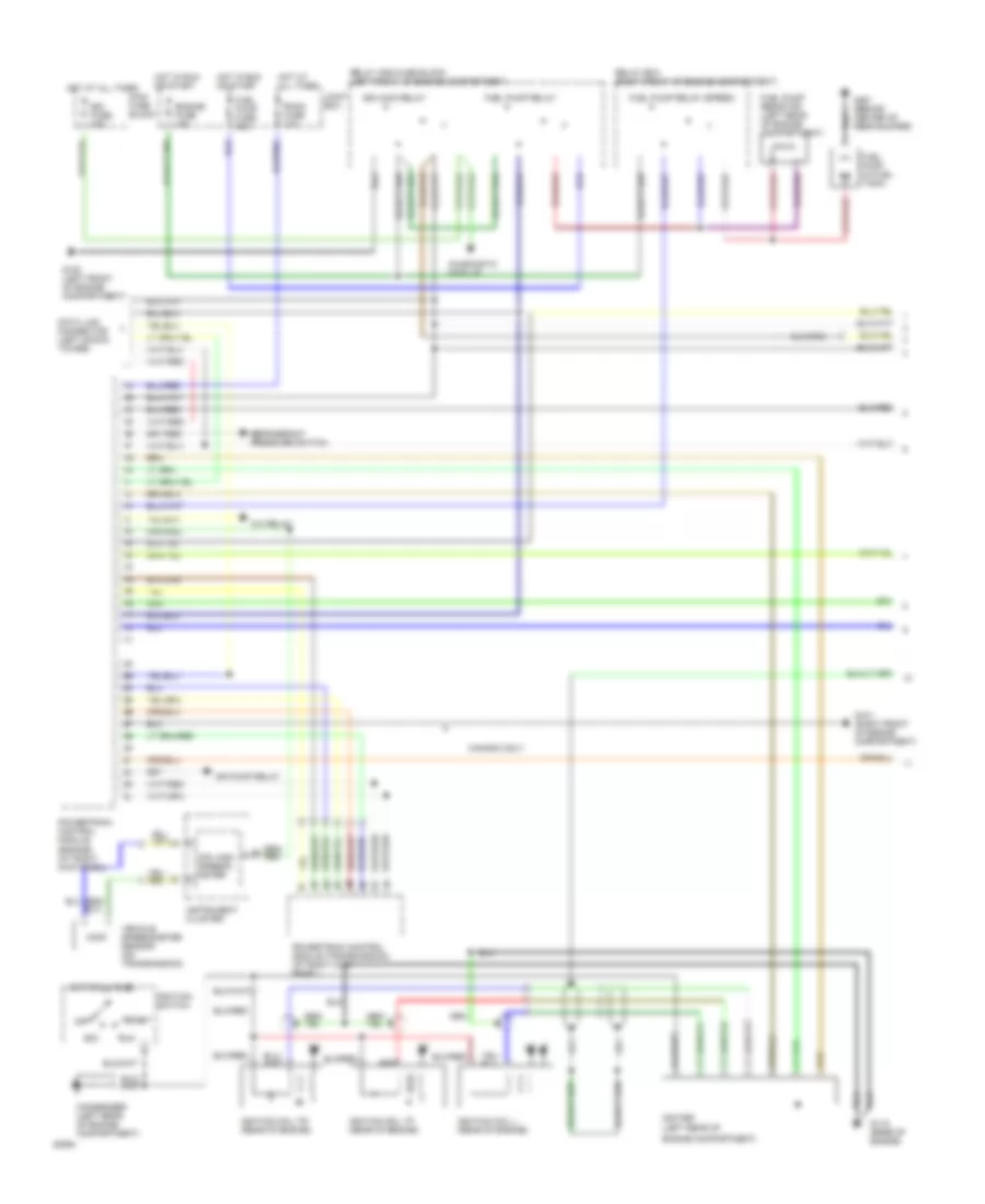
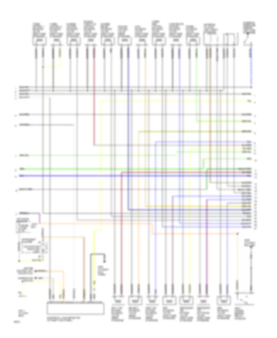
1.3L, Engine Performance Wiring Diagrams, A/T (1 of 3) for Mazda RX-7 1994
 https://portal-diagnostov.com/license.html
Automotive Electricians Portal FZCO
Automotive Electricians Portal FZCO
https://portal-diagnostov.com/license.html
https://portal-diagnostov.com/license.html
Automotive Electricians Portal FZCO
Automotive Electricians Portal FZCOList of elements for 1.3L, Engine Performance Wiring Diagrams, A/T (1 of 3) for Mazda RX-7 1994:
- (left rear of
- A/c relay
- Acc
- Air pump relay
- Canada only
- Condenser (left rear of engine compartment)
- Cpu and speedo- meter
- Data link connector (left shock tower)
- Diagnostic module
- Egi fuse 30a
- Egi main relay
- Engine compartment)
- Engine fuse 15a
- Fuel pump (in fuel tank)
- Fuel pump fuse 20a
- Fuel pump relay
- Fuel pump relay (speed)
- Fuel pump resistor (left rear of engine compartment)
- G100 (left front of engine compartment)
- G101 (right front of engine compartment)
- G115 (rear of engine)
- G407 (behind center of rear bumper)
- Hot at all times
- Hot in run or start
- Igniter
- Ignition coil l (rear of engine)
- Ignition coil tf (rear of engine)
- Ignition coil tr (rear of engine)
- Ignition switch
- Instrument cluster
- Joint box
- Main fuse block
- Off
- Powertrain control module (engine) (at right kick panel)
- Powertrain control module (transmission) (at right kick panel)
- Red
- Refrigerant pressure switch
- Relay and fuse block (left front of engine compartment)
- Relay box (right front of engine compartment)
- Room fuse 10a
- Run
- Start
- Vehicle speedometer sensor (on transmission)
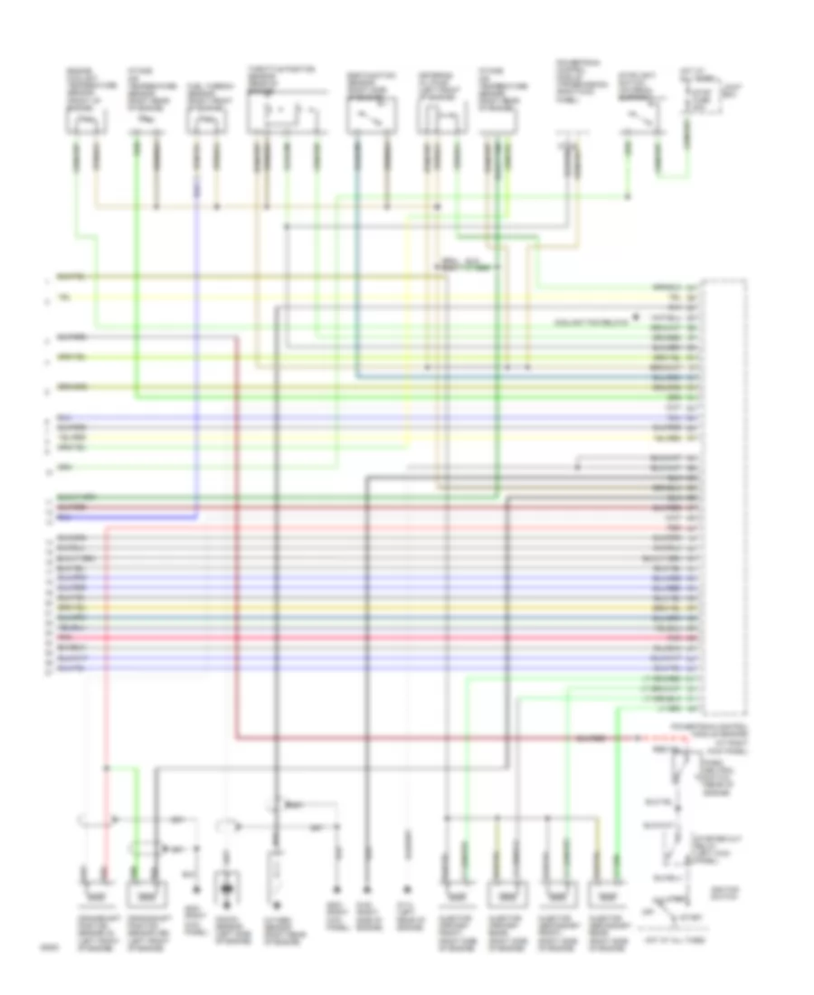
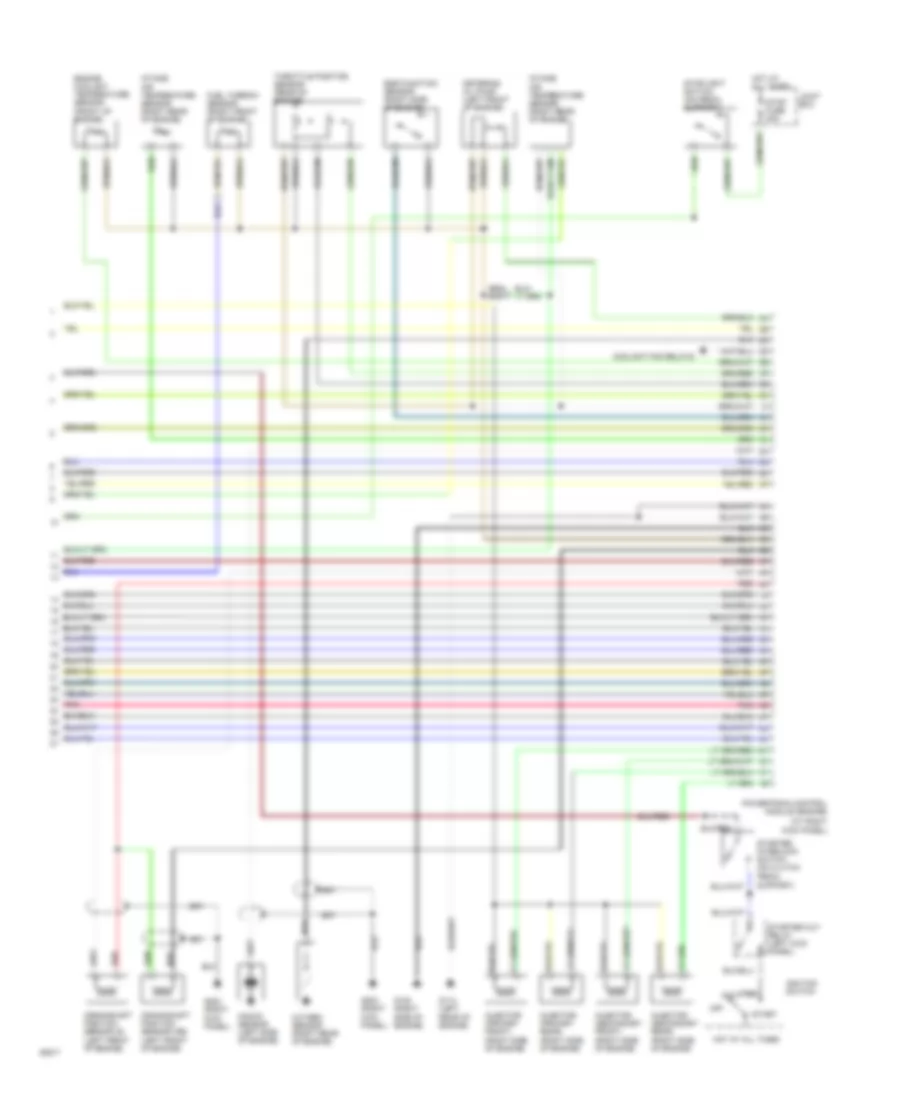
1.3L, Engine Performance Wiring Diagrams, A/T (2 of 3) for Mazda RX-7 1994
 https://portal-diagnostov.com/license.html
Automotive Electricians Portal FZCO
Automotive Electricians Portal FZCO
https://portal-diagnostov.com/license.html
https://portal-diagnostov.com/license.html
Automotive Electricians Portal FZCO
Automotive Electricians Portal FZCOList of elements for 1.3L, Engine Performance Wiring Diagrams, A/T (2 of 3) for Mazda RX-7 1994:
- (left side of engine)
- Aws solenoid valve (right side of engine)
- Charge control solenoid valve (right side of engine)
- Charge relief solenoid valve (right side of engine)
- Combination switch
- Cpu 1 (in joint box)
- Double throttle control solenoid valve (right side of engine)
- Egr solenoid valve (right side of engine)
- Electrical load detector (at right kick panel)
- G203 (at right kick panel)
- G305 (at right b-pillar)
- Heat hazard sensor (below console)
- Heater control unit (fan switch)
- Hot in run or start
- Idle air control valve (rear of engine)
- Instrument cluster
- Joint box
- Malfunction indicator lamp
- Meter fuse 15a
- Metering oil pump (left front of engine)
- Pnk
- Port air bypass solenoid valve (rear of engine)
- Prc solenoid valve (right side of engine)
- Purge solenoid valve (right side of engine)
- Relief 2 solenoid valve (rear of engine)
- Secondary air bypass valve (right side of engine)
- Secondary air switching valve (right side of engine)
- Split air bypass solenoid valve (rear of engine)
- Steering pressure sensor
- Turbo control 1 solenoid valve (right side of engine)
- Turbo control 2 solenoid valve (right side of engine)
- Turbo pre- control solenoid valve (right side of engine)
- Wastegate control solenoid valve (right side of engine)
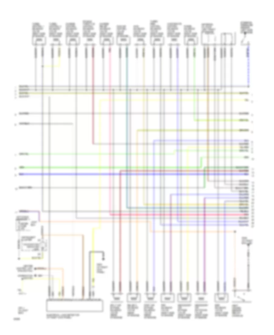
1.3L, Engine Performance Wiring Diagrams, A/T (3 of 3) for Mazda RX-7 1994
 https://portal-diagnostov.com/license.html
Automotive Electricians Portal FZCO
Automotive Electricians Portal FZCO
https://portal-diagnostov.com/license.html
https://portal-diagnostov.com/license.html
Automotive Electricians Portal FZCO
Automotive Electricians Portal FZCOList of elements for 1.3L, Engine Performance Wiring Diagrams, A/T (3 of 3) for Mazda RX-7 1994:
- (at right kick panel)
- Acc
- Coolant fan relays
- Crankshaft position sensor (g) (left front of engine)
- Crankshaft position sensor (ne) (left front of engine)
- Egr function sensor (right side of engine)
- Engine coolant temperature sensor (front of engine)
- Fuel thermo- sensor (right front of engine)
- G114 (left
- G120 (right
- G203 (right
- Hot at all times
- Ignition switch
- Injector (primary front) (right side of engine)
- Injector (primary rear) (right side of engine)
- Injector (secondary front) (right side of engine)
- Injector (secondary rear) (right side of engine)
- Intake air temperature sensor (right rear of engine)
- Joint box
- Kick panel)
- Knock sensor (left side of engine)
- Metering oil pump (left front of engine)
- Off
- Oxygen sensor (right rear of engine)
- Panel)
- Park/ neutral switch (rear of engine)
- Pnk
- Powertrain control module (engine)
- Powertrain control module (transmission) (right kick
- Rear of engine)
- Red
- Run
- Side of engine)
- Start
- Starter cut relay (left kick panel)
- Stop fuse 20a
- Stoplight switch (on pedal support)
- Throttle position sensor (rear of engine)
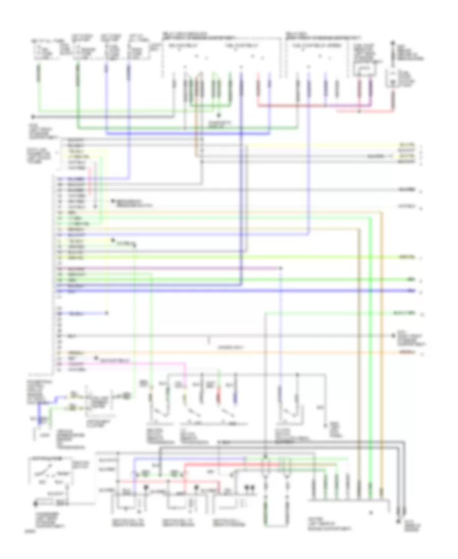
1.3L, Engine Performance Wiring Diagrams, M/T (1 of 3) for Mazda RX-7 1994
 https://portal-diagnostov.com/license.html
Automotive Electricians Portal FZCO
Automotive Electricians Portal FZCO
https://portal-diagnostov.com/license.html
https://portal-diagnostov.com/license.html
Automotive Electricians Portal FZCO
Automotive Electricians Portal FZCOList of elements for 1.3L, Engine Performance Wiring Diagrams, M/T (1 of 3) for Mazda RX-7 1994:
- (left rear of
- 1-2 switch (rear of transmission)
- 1st
- 2nd
- A/c relay
- Acc
- Air pump relay
- Canada only
- Clutch switch (on clutch pedal support)
- Condenser (left rear of engine compartment)
- Cpu and speedo- meter
- Data link connector (left shock tower)
- Diagnostic module
- Egi fuse 30a
- Egi main relay
- Engine compartment)
- Engine fuse 15a
- Fuel pump (in fuel tank)
- Fuel pump fuse 20a
- Fuel pump relay
- Fuel pump relay (speed)
- Fuel pump resistor (left rear of engine compartment)
- G100 (left front of engine compartment)
- G101 (right front of engine compartment)
- G115 (rear of engine)
- G200 (left kick panel)
- G407 (behind center of rear bumper)
- Hot at all times
- Hot in run or start
- Igniter
- Ignition coil l (rear of engine)
- Ignition coil tf (rear of engine)
- Ignition coil tr (rear of engine)
- Ignition switch
- Instrument cluster
- Joint box
- Main fuse block
- Neutral switch (rear of transmission)
- Off
- Powertrain control module (engine) (at right kick panel)
- Red
- Refrigerant pressure switch
- Relay and fuse block (left front of engine compartment)
- Relay box (right front of engine compartment)
- Room fuse 10a
- Run
- Start
- Vehicle speedometer sensor (on transmission)
1.3L, Engine Performance Wiring Diagrams, M/T (2 of 3) for Mazda RX-7 1994
 https://portal-diagnostov.com/license.html
Automotive Electricians Portal FZCO
Automotive Electricians Portal FZCO
https://portal-diagnostov.com/license.html
https://portal-diagnostov.com/license.html
Automotive Electricians Portal FZCO
Automotive Electricians Portal FZCOList of elements for 1.3L, Engine Performance Wiring Diagrams, M/T (2 of 3) for Mazda RX-7 1994:
- (left side of engine)
- Aws solenoid valve (right side of engine)
- Charge control solenoid valve (right side of engine)
- Charge relief solenoid valve (right side of engine)
- Combination switch
- Cpu 1 (in joint box)
- Double throttle control solenoid valve (right side of engine)
- Egr solenoid valve (right side of engine)
- Electrical load detector (at right kick panel)
- G203 (at right kick panel)
- G305 (at right b-pillar)
- Heat hazard sensor (below console)
- Heater control unit (fan switch)
- Hot in run or start
- Idle air control valve (rear of engine)
- Instrument cluster
- Joint box
- Malfunction indicator lamp
- Meter fuse 15a
- Metering oil pump (left front of engine)
- Pnk
- Port air bypass solenoid valve (rear of engine)
- Prc solenoid valve (right side of engine)
- Purge solenoid valve (right side of engine)
- Relief 2 solenoid valve (rear of engine)
- Secondary air bypass valve (right side of engine)
- Secondary air switching valve (right side of engine)
- Split air bypass solenoid valve (rear of engine)
- Steering pressure sensor
- Turbo control 1 solenoid valve (right side of engine)
- Turbo control 2 solenoid valve (right side of engine)
- Turbo pre- control solenoid valve (right side of engine)
- Wastegate control solenoid valve (right side of engine)
1.3L, Engine Performance Wiring Diagrams, M/T (3 of 3) for Mazda RX-7 1994
 https://portal-diagnostov.com/license.html
Automotive Electricians Portal FZCO
Automotive Electricians Portal FZCO
https://portal-diagnostov.com/license.html
https://portal-diagnostov.com/license.html
Automotive Electricians Portal FZCO
Automotive Electricians Portal FZCOList of elements for 1.3L, Engine Performance Wiring Diagrams, M/T (3 of 3) for Mazda RX-7 1994:
- (at right kick panel)
- Acc
- Coolant fan relays
- Crankshaft position sensor (g) (left front of engine)
- Crankshaft position sensor (ne) (left front of engine)
- Egr function sensor (right side of engine)
- Engine coolant temperature sensor (front of engine)
- Fuel thermo- sensor (right front of engine)
- G114 (left
- G120 (right
- G203 (right
- Hot at all times
- Ignition switch
- Injector (primary front) (right side of engine)
- Injector (primary rear) (right side of engine)
- Injector (secondary front) (right side of engine)
- Injector (secondary rear) (right side of engine)
- Intake air temperature sensor (right rear of engine)
- Joint box
- Kick panel)
- Knock sensor (left side of engine)
- Metering oil pump (left front of engine)
- Off
- Oxygen sensor (right rear of engine)
- Pnk
- Powertrain control module (engine)
- Rear of engine)
- Red
- Run
- Side of engine)
- Start
- Starter cut relay (left kick panel)
- Starter interlock switch (on clutch pedal support)
- Stop fuse 20a
- Stoplight switch (on pedal support)
- Throttle position sensor (rear of engine)
EXTERIOR LIGHTS
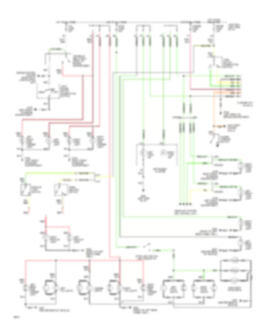
Exterior Light Wiring Diagram for Mazda RX-7 1994
 https://portal-diagnostov.com/license.html
Automotive Electricians Portal FZCO
Automotive Electricians Portal FZCO
https://portal-diagnostov.com/license.html
https://portal-diagnostov.com/license.html
Automotive Electricians Portal FZCO
Automotive Electricians Portal FZCOList of elements for Exterior Light Wiring Diagram for Mazda RX-7 1994:
- (a/t)
- (m/t)
- Anti-theft system (cpu 2)
- Back-up light switch
- Canada
- Engine control system (electrical load control unit)
- Flasher unit (in cpu 2)
- G108 (left front of engine compartment)
- G109 (right front of engine compartment)
- G202 (left side of i/p)
- G402 (front of left rear wheel well)
- G407 (center rear of vehicle)
- Hazard fuse 15a
- Hazard warning switch
- Head
- Headlight system (drl control unit)
- High mount stoplights
- Hot at all times
- Hot in run and start
- Instrument cluster
- Joint box (left side of i/p)
- Left back-up light
- Left front side marker light
- Left front turn light
- Left park light
- Left rear side marker light
- Left rear turn light
- Left stop- lights
- Left taillights
- Left turn ind
- License lights
- Light/ dimmer switch (combination switch)
- Meter fuse 15a
- Nca
- Off
- Park/ neutral switch
- Red
- Right back-up light
- Right front side marker light
- Right front turn light
- Right park light
- Right rear side marker light
- Right rear turn light
- Right stop- lights
- Right taillights
- Right turn ind
- Stop fuse 20a
- Stop light switch (left side of i/p)
- Tail fuse 15a
- Tns
- Tns relay (relay box) (front of engine compartment)
- Turn switch (combination switch)
- Usa
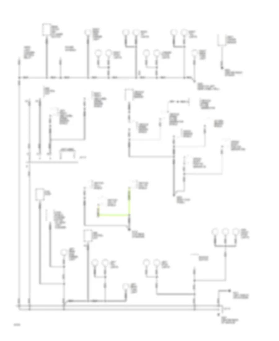
GROUND DISTRIBUTION
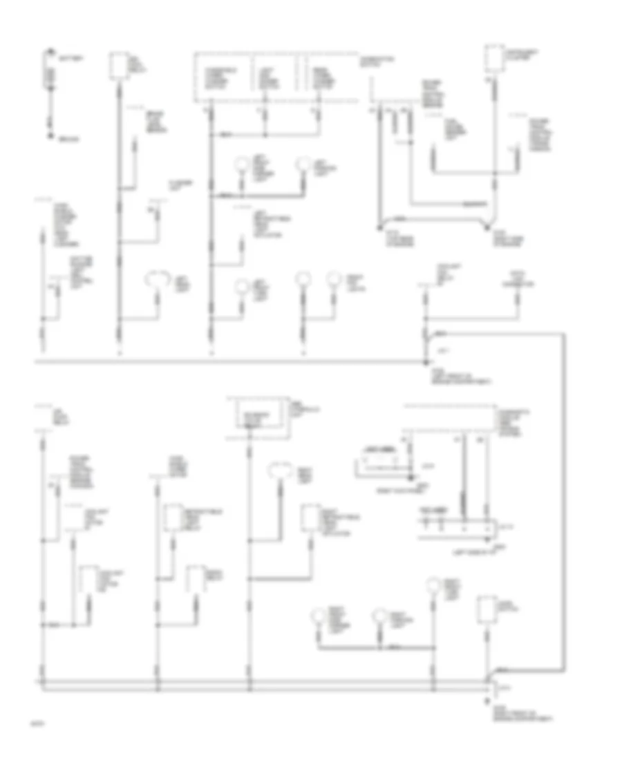
Ground Distribution Wiring Diagram (1 of 3) for Mazda RX-7 1994
 https://portal-diagnostov.com/license.html
Automotive Electricians Portal FZCO
Automotive Electricians Portal FZCO
https://portal-diagnostov.com/license.html
https://portal-diagnostov.com/license.html
Automotive Electricians Portal FZCO
Automotive Electricians Portal FZCOList of elements for Ground Distribution Wiring Diagram (1 of 3) for Mazda RX-7 1994:
- (left side of i/p)
- (not used)
- (right kick panel)
- Abs hydraulic unit
- Air pump relay
- Battery
- Brake fluid level sensor
- Combination switch
- Coolant fan motor #1
- Coolant fan motor #2
- Coolant fan relay #3
- Data link connector
- Daytime running light (drl) control unit
- Diagnostic module (srs air bag system)
- Egi main relay
- Flasher unit
- Front fog lights
- Fuel gauge sender unit
- G108 (left front of engine compartment)
- G109 (right front of engine compartment)
- G115 (top rear of engine)
- G120 (right side of engine)
- G202
- G203
- Ground
- Hood switch
- Instrument cluster
- J/c 1
- J/c 10
- J/c 2
- J/c 9
- Left front side marker light
- Left front turn light
- Left head- light
- Left parking light
- Left retractable head- light actuator
- Light and dimmer switch
- Nca
- Power- train control module (engine)
- Power- train control module (engine) (canada)
- Power- train control module (trans- mission)
- Radio relay
- Rear wiper/ washer switch
- Retractable head- light relay
- Right front side marker light
- Right front turn light
- Right head- light
- Right parking light
- Right retractable head- light actuator
- Solenoid valve relay
- Wind- shield washer motor (w/o head- light cleaner)
- Wind- shield wiper motor
- Windshield wiper/ washer switch
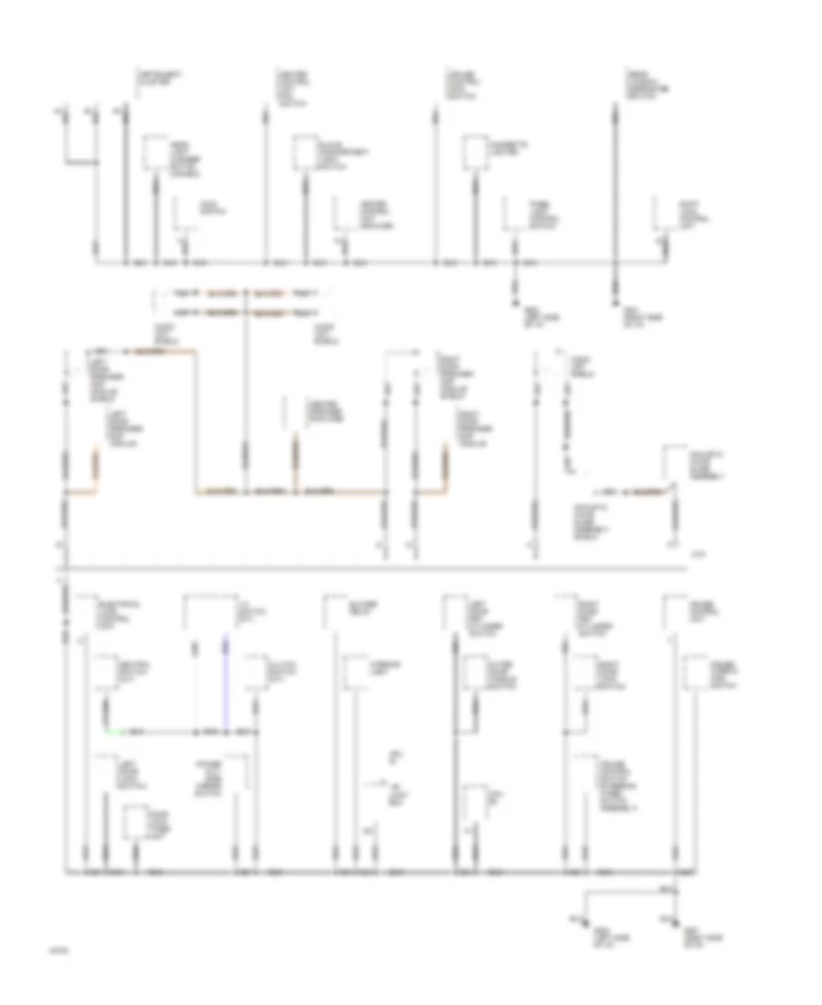
Ground Distribution Wiring Diagram (2 of 3) for Mazda RX-7 1994
 https://portal-diagnostov.com/license.html
Automotive Electricians Portal FZCO
Automotive Electricians Portal FZCO
https://portal-diagnostov.com/license.html
https://portal-diagnostov.com/license.html
Automotive Electricians Portal FZCO
Automotive Electricians Portal FZCOList of elements for Ground Distribution Wiring Diagram (2 of 3) for Mazda RX-7 1994:
- (not used)
- Abs control unit
- Back- up lights
- Buckle switch
- Crank- shaft positon sensor (g)
- Crank- shaft positon sensor (ne)
- Fuel pump
- G115 (top rear of engine)
- G203 (right kick panel)
- G402 (front of left rear wheel well)
- G407 (center rear of vehicle)
- G411 (left side of hatch door)
- G908 (center front of roof)
- Head- light cleaner motor & relay
- Heat hazard sensor
- High mount stop- lights
- Ignition coil-l shield
- Ignition coil-tf shield
- Ignition coil-tr shield
- J/c 12
- J/c 13
- Knock sensor shield
- Left front abs wheel speed sensor shield
- Left rear side marker light
- Left rear turn light
- Left stop lights
- Left tail lights
- License plate lights
- Oxygen sensor shield
- Power antenna
- Rear hatch key cylinder switch
- Right front abs wheel speed sensor shield
- Right rear side marker light
- Right rear turn light
- Right stop lights
- Right tail lights
- Vehicle speed pulse generator
- Vehicle speed pulse generator shield
- Vehicle speed sensor
- Vehicle speed sensor shield
- Wind- shield washer motor (w/ head- light cleaner)
Ground Distribution Wiring Diagram (3 of 3) for Mazda RX-7 1994
 https://portal-diagnostov.com/license.html
Automotive Electricians Portal FZCO
Automotive Electricians Portal FZCO
https://portal-diagnostov.com/license.html
https://portal-diagnostov.com/license.html
Automotive Electricians Portal FZCO
Automotive Electricians Portal FZCOList of elements for Ground Distribution Wiring Diagram (3 of 3) for Mazda RX-7 1994:
- 1-2 switch (m/t)
- Acoustic wave guide assembly
- Acoustic wave guide assembly shield
- Audio unit shield
- Blower relay
- Center speaker amplifier
- Cigarette lighter
- Clutch switch (m/t)
- Cpu #1
- Cpu #2
- Cruise control main switch
- Cruise control switch (steering wheel switch assembly)
- Cruise control unit
- Door lock timer unit
- Electrical load control unit
- G201 (right side of i/p)
- G202 (left side of i/p)
- Glove compartment light switch
- Head- light cleaner switch (canada)
- Heater control unit amplifier
- Heater control unit fan switch
- Hold switch
- Instrument cluster
- Interior light
- J/c 8
- Joint box
- Left door key cylinder switch
- Left door lock switch
- Left door speaker/ amp module
- Left door speaker/ amp module shield
- Nca
- Neutral switch (m/t)
- Outer door handle switch
- Panel light control switch
- Power out- side mirror switch
- Power window main switch
- Rear window defroster switch
- Right door key cylinder switch
- Right door lock switch
- Right door speaker/ amp module
- Right door speaker/ amp module shield
- Shift- lock control unit
HEADLIGHTS
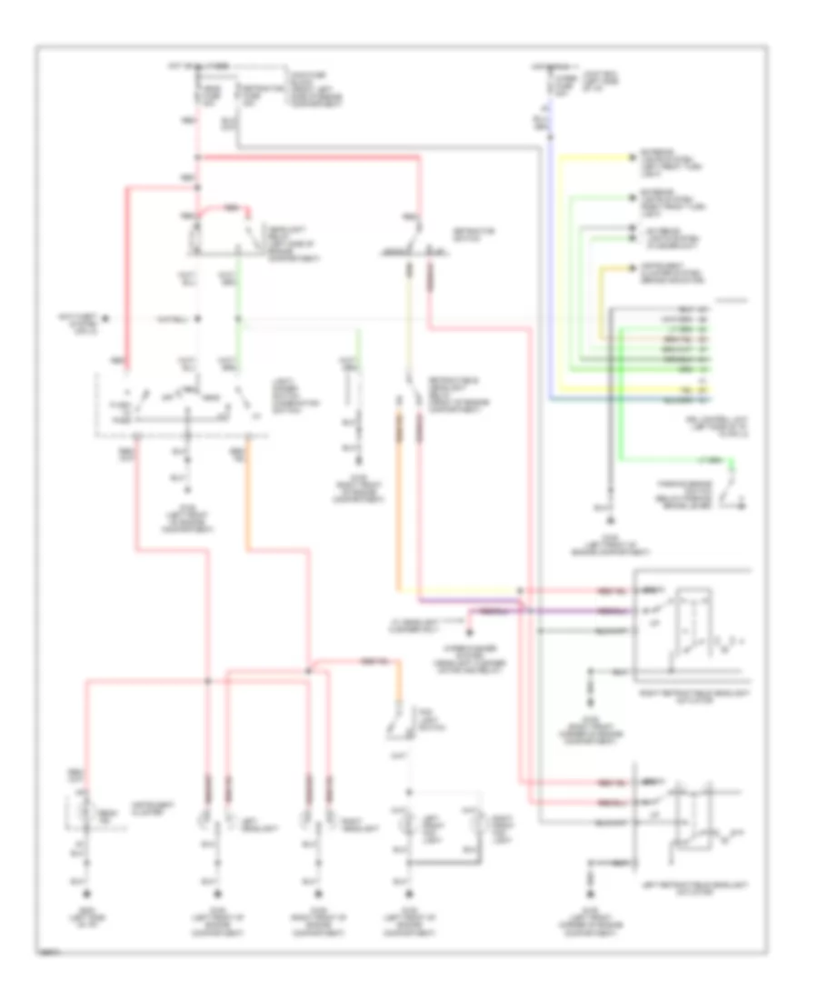
Headlight Wiring Diagram, with DRL for Mazda RX-7 1994
 https://portal-diagnostov.com/license.html
Automotive Electricians Portal FZCO
Automotive Electricians Portal FZCO
https://portal-diagnostov.com/license.html
https://portal-diagnostov.com/license.html
Automotive Electricians Portal FZCO
Automotive Electricians Portal FZCOList of elements for Headlight Wiring Diagram, with DRL for Mazda RX-7 1994:
- Anti-theft system (cpu 2)
- Beam ind
- Down
- Drl control unit (left side of i/p, in cpu 2)
- Exterior lights system (flasher unit)
- Exterior lights system (left front turn light)
- Exterior lights system (right front turn light)
- Flash to pass
- Fog light switch
- G108 (left front corner of engine compartment)
- G108 (left front of engine compartment)
- G109 (right front corner of engine compartment)
- G109 (right front of engine compartment)
- G202 (left side of i/p)
- Head
- Head fuse 30a
- Headlight relay (left side of engine compartment)
- Hot at all times
- Hot in run
- Instrument cluster
- Instrument cluster system (brake indicator)
- Joint box (left side of i/p)
- Left front fog light
- Left headlight
- Left retractable headlight actuator
- Light/ dimmer switch (combination switch)
- Main fuse block (front left side of engine compartment)
- Off
- Parking brake switch (below parking brake lever)
- Red
- Retractable headlight relay (front of engine compartment)
- Retractor fuse 30a
- Retractor switch
- Right front fog light
- Right headlight
- Right retractable headlight actuator
- Tns
- W/ headlight cleaner only
- Wiper fuse 20a
- Wiper/washer system (headlight cleaner motor and relay)
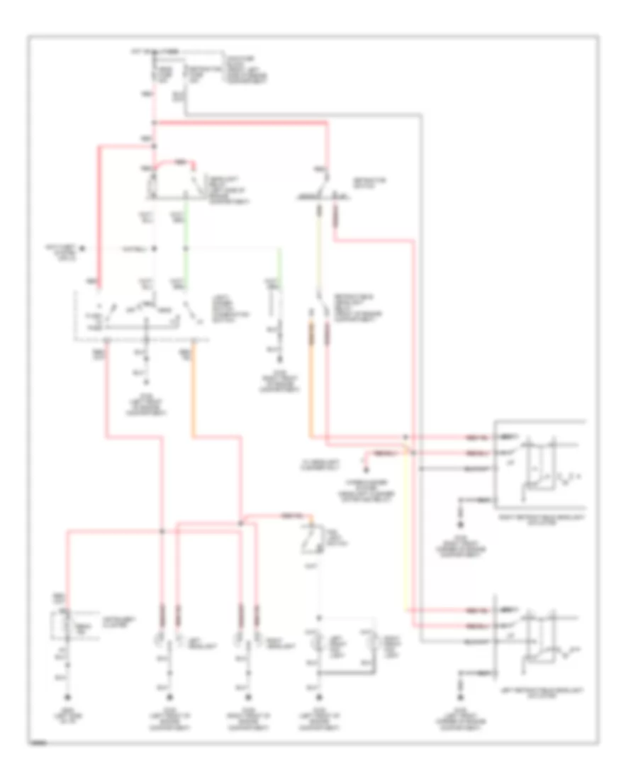
Headlight Wiring Diagram, without DRL for Mazda RX-7 1994
 https://portal-diagnostov.com/license.html
Automotive Electricians Portal FZCO
Automotive Electricians Portal FZCO
https://portal-diagnostov.com/license.html
https://portal-diagnostov.com/license.html
Automotive Electricians Portal FZCO
Automotive Electricians Portal FZCOList of elements for Headlight Wiring Diagram, without DRL for Mazda RX-7 1994:
- Anti-theft system (cpu 2)
- Beam ind
- Down
- Flash to pass
- Fog light switch
- G108 (left front corner of engine compartment)
- G108 (left front of engine compartment)
- G109 (right front corner of engine compartment)
- G109 (right front of engine compartment)
- G202 (left side of i/p)
- Head
- Head fuse 30a
- Headlight relay (left side of engine compartment)
- Hot at all times
- Instrument cluster
- Left front fog light
- Left headlight
- Left retractable headlight actuator
- Light/ dimmer switch (combination switch)
- Main fuse block (front left side of engine compartment)
- Off
- Red
- Retractable headlight relay (front of engine compartment)
- Retractor fuse 30a
- Retractor switch
- Right front fog light
- Right headlight
- Right retractable headlight actuator
- Tns
- W/ headlight cleaner only
- Wiper/washer system (headlight cleaner motor and relay)
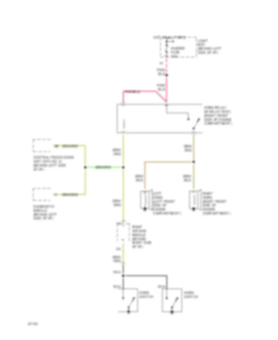
HORN
Horn Wiring Diagram for Mazda RX-7 1994
 https://portal-diagnostov.com/license.html
Automotive Electricians Portal FZCO
Automotive Electricians Portal FZCO
https://portal-diagnostov.com/license.html
https://portal-diagnostov.com/license.html
Automotive Electricians Portal FZCO
Automotive Electricians Portal FZCOList of elements for Horn Wiring Diagram for Mazda RX-7 1994:
- Central processing unit (cpu no. 2) (behind left side of i/p)
- Diagnostic module (behind left side of i/p)
- Hazard fuse 15a
- Horn relay (in relay box) (right front side of engine compartment)
- Horn switch
- Hot at all times
- Joint box (behind left side of i/p)
- Left horn (left front side of engine compartment)
- Nca
- Right air bag module (behind right side of i/p)
- Right horn (right front side of engine compartment)
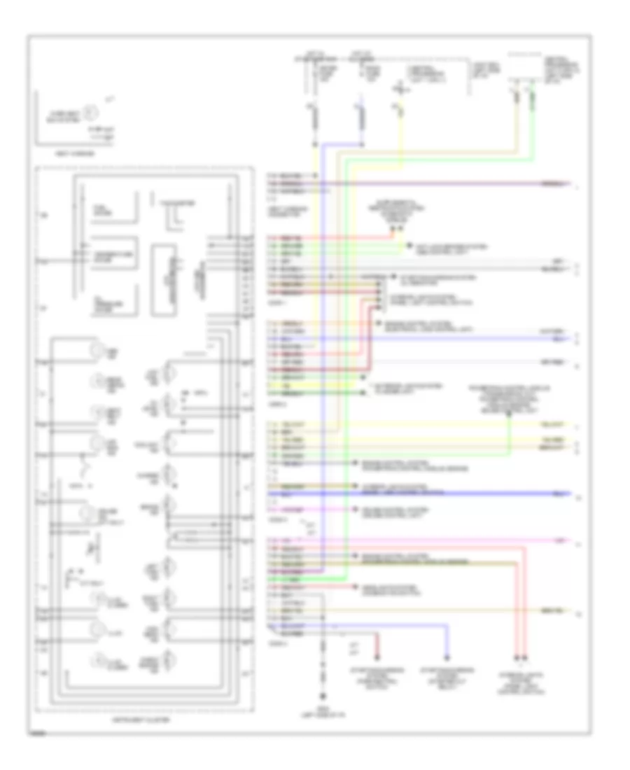
INSTRUMENT CLUSTER
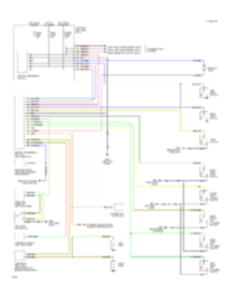
Instrument Cluster Wiring Diagram (1 of 2) for Mazda RX-7 1994
 https://portal-diagnostov.com/license.html
Automotive Electricians Portal FZCO
Automotive Electricians Portal FZCO
https://portal-diagnostov.com/license.html
https://portal-diagnostov.com/license.html
Automotive Electricians Portal FZCO
Automotive Electricians Portal FZCOList of elements for Instrument Cluster Wiring Diagram (1 of 2) for Mazda RX-7 1994:
- A/t
- Abs ind
- Air bag ind
- Anti-lock brakes system (abs control unit)
- Brake ind
- Central processing unit 1 (cpu 1)
- Central processing unit 2 (cpu 2) (left side of i/p)
- Charge ind
- Check engine ind
- Conn 1
- Conn 2
- Conn 3
- Conn 4
- Coolant ind
- Cpu and speedometer
- Cruise control system (cruise control unit)
- Cruise ind (m/t only)
- Engine control system (electrical load control unit)
- Engine control system (powertrain control module) (engine)
- Exterior lights system (flasher unit)
- Fuel gauge
- G202 (left side of i/p)
- Headlights system (combination switch)
- Heat warning
- Heat warning connector
- High beam ind
- Hot at all times
- Hot in start and run
- Illum
- Illum (2 used)
- Instrument cluster
- Interior lights system (panel light control switch)
- Joint box (left side of i/p)
- Lcd (odo/trip meter)
- Left turn ind
- Low fuel ind
- M/t
- M/t only
- Meter fuse 15a
- Oil level ind
- Oil pressure gauge
- Over heat exh system
- Powertrain control module (transmission) (a/t) powertrain control module (engine) cruise control unit
- Rear defog ind
- Right turn ind
- Room fuse 10a
- Seat belt ind
- Starting/charging system (alternator)
- Starting/charging system (park/neutral switch)
- Starting/charging system (starter cut relay)
- Tachometer
- Temperature gauge
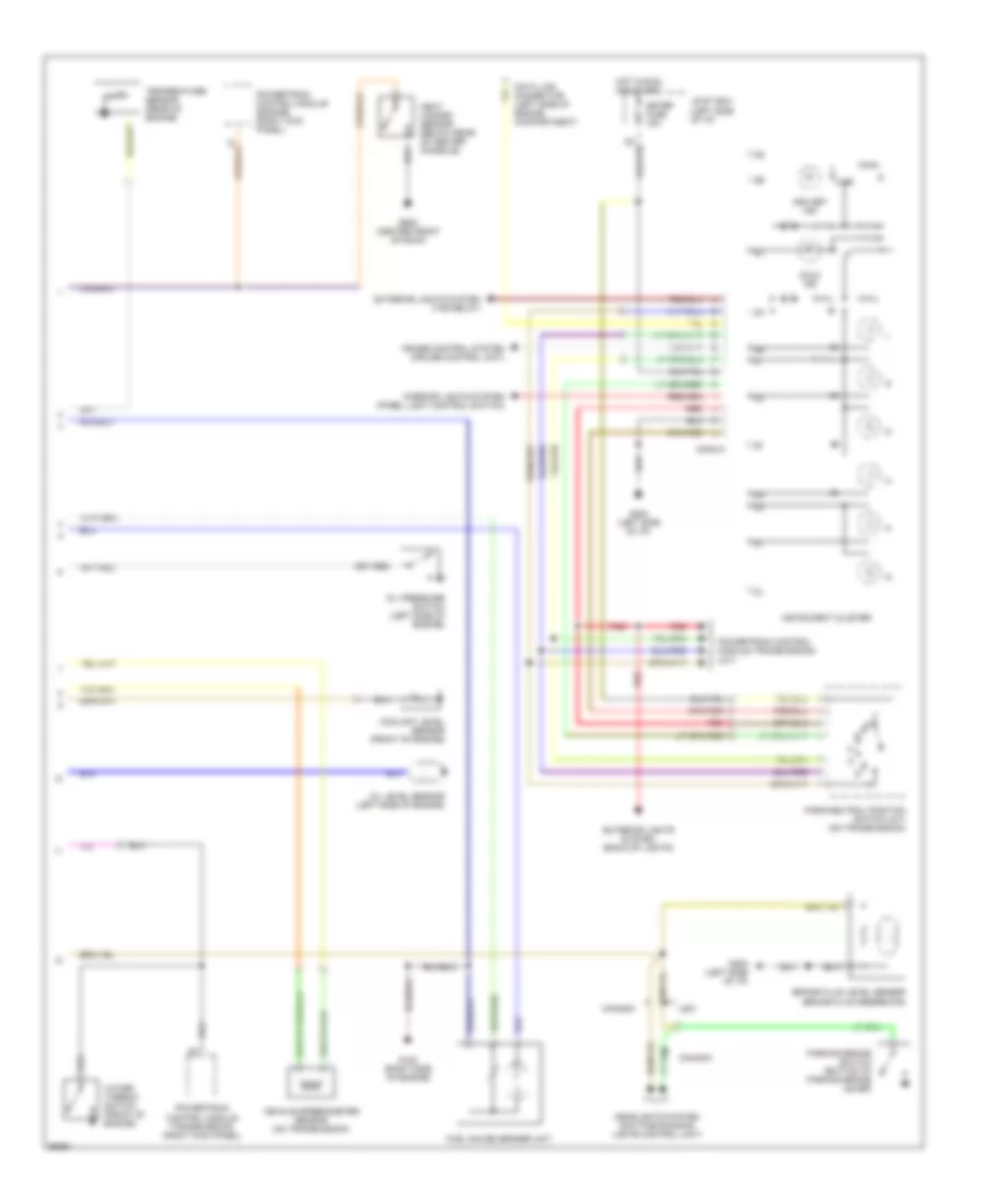
Instrument Cluster Wiring Diagram (2 of 2) for Mazda RX-7 1994
 https://portal-diagnostov.com/license.html
Automotive Electricians Portal FZCO
Automotive Electricians Portal FZCO
https://portal-diagnostov.com/license.html
https://portal-diagnostov.com/license.html
Automotive Electricians Portal FZCO
Automotive Electricians Portal FZCOList of elements for Instrument Cluster Wiring Diagram (2 of 2) for Mazda RX-7 1994:
- Asc set ind
- Brake fluid level sensor (brake fluid reservoir)
- Canada
- Conn 5
- Coolant level sensor (front of engine)
- Cruise control system (cruise control unit)
- Data link connector (left side of engine compartment)
- Exterior lights system (back-up lights)
- Exterior lights system (tns relay)
- Fuel gauge sender unit
- G120 (right side of engine)
- G202 (left side of i/p)
- G908 (center front of roof)
- Headlights system (daytime running lights control unit)
- Heat hazard sensor (below rear of center console)
- Hold ind
- Hot in run and start
- Instrument cluster
- Interior lights system (panel light control switch)
- Joint box (left side of i/p)
- Meter fuse 15a
- Oil level sensor (left side of engine)
- Oil pressure switch (left side of engine)
- Park/neutral position switch (a/t) (on transmission)
- Parking brake switch (bottom of parking brake lever)
- Powertrain control module (engine) (right kick panel)
- Powertrain control module (transmission) (a/t)
- Powertrain control module (transmission) (right kick panel)
- Red
- Temperature sensor (rear of engine)
- Usa
- Vehicle speedometer sensor (on transmission)
- Water thermo- switch (front of engine)
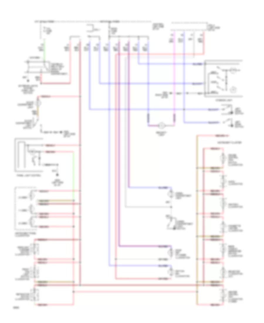
INTERIOR LIGHTS
Interior Light Wiring Diagram for Mazda RX-7 1994
 https://portal-diagnostov.com/license.html
Automotive Electricians Portal FZCO
Automotive Electricians Portal FZCO
https://portal-diagnostov.com/license.html
https://portal-diagnostov.com/license.html
Automotive Electricians Portal FZCO
Automotive Electricians Portal FZCOList of elements for Interior Light Wiring Diagram for Mazda RX-7 1994:
- (1 used)
- (2 used)
- Ashtray illumination
- Audio illumination
- Cargo compartment light
- Cargo compartment light switch
- Cigarette lighter illumination
- Cpu 1
- Cpu 2 (left side of i/p)
- Cruise control main switch illumination
- Door
- Door key cylinder illumination
- Exterior lights system (park light switch)
- Front fog light switch illumination
- G201 (right side of i/p)
- G202 (left side of i/p)
- Glove compartment light
- Glove compartment light switch
- Headlight cleaner switch illumination
- Heater control unit illumination (4 used)
- Hot at all times
- Ignition key illumination
- Instrument cluster
- Instrument panel illumination
- Interior light
- Joint box (left side of i/p)
- Left door switch
- Panel light control
- Rear window defroster switch illumination
- Retractor switch illumination
- Room fuse 10a
- Security light
- Selector illumination (a/t)
- Spot
- Tail fuse 15a
- Tns relay (relay box) (front of engine compartment)
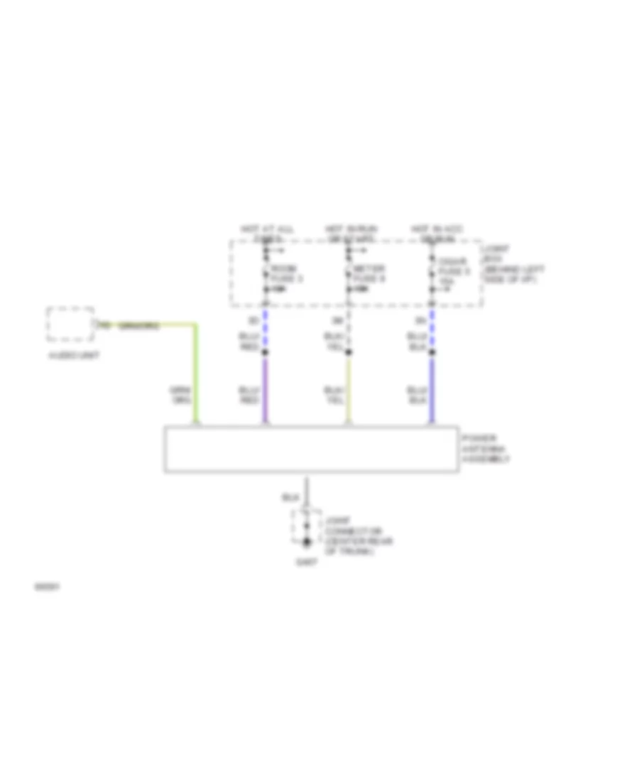
POWER ANTENNA
Power Antenna Wiring Diagram for Mazda RX-7 1994
 https://portal-diagnostov.com/license.html
Automotive Electricians Portal FZCO
Automotive Electricians Portal FZCO
https://portal-diagnostov.com/license.html
https://portal-diagnostov.com/license.html
Automotive Electricians Portal FZCO
Automotive Electricians Portal FZCOList of elements for Power Antenna Wiring Diagram for Mazda RX-7 1994:
- Audio unit
- Cigar fuse 5 15a
- G407
- Hot at all times
- Hot in acc or run
- Hot in run or start
- Joint box (behind left side of i/p)
- Joint connector (center rear of trunk)
- Meter fuse 9 15a
- Power antenna assembly
- Room fuse 3 10a
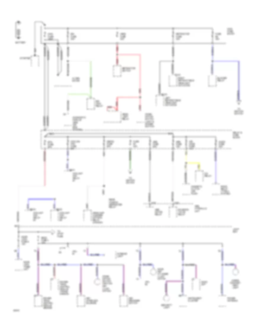
POWER DISTRIBUTION
Power Distribution Wiring Diagram (1 of 3) for Mazda RX-7 1994
 https://portal-diagnostov.com/license.html
Automotive Electricians Portal FZCO
Automotive Electricians Portal FZCO
https://portal-diagnostov.com/license.html
https://portal-diagnostov.com/license.html
Automotive Electricians Portal FZCO
Automotive Electricians Portal FZCOList of elements for Power Distribution Wiring Diagram (1 of 3) for Mazda RX-7 1994:
- 0-02
- 0-03
- A/c relay
- Abs fuse 15a
- Abs fuse 60a
- Abs hydraulic unit
- Abs motor relay
- Air cond fuse 15a
- Alter- nator
- Audio fuse 30a
- Audio unit
- B2-01
- B2-02
- B2-04
- Battery
- Blower relay
- Btn fuse 60a
- Cargo compart- ment light
- Combi- nation switch (ignition key illumi- nation)
- Combi- nation switch (light & dimmer switch)
- Coolant fan relay #1
- Coolant fan relay #2
- Coolant fan relay #4
- Cooling fan fuse 60a
- Cpu #1
- Cpu #2
- Defog fuse 60a
- Diagnostic module (srs air bag system)
- Door key cylinder illumi- nation
- Door lock fuse 6 10a
- Door lock timer unit
- E1-03
- E1-04
- Egi fuse 30a
- Egi main relay
- Fuse b1 40a
- Fuse b2 40a
- Head fuse 30a
- Head- light relay
- Headlamp cleaner motor & relay (canada)
- Instrument cluster
- Interior light
- Joint box
- Key interlock solenoid
- Key reminder switch
- Left retractable headlight actuator
- Magnetic clutch (air pump)
- Main fuse 120a
- Main fuse block
- Power antenna
- Power- train control module (engine)
- Power- train control module (trans- mission)
- Radio relay (type 2 system)
- Rear window defroster relay
- Red
- Relay & fuse block
- Retractor fuse 30a
- Retractor switch
- Right retractable headlight actuator
- Room fuse 3 10a
- Security light
- Solenoid valve relay
- Starter
- To ignition switch
- To stop fuse
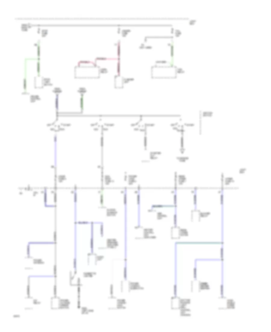
Power Distribution Wiring Diagram (2 of 3) for Mazda RX-7 1994
 https://portal-diagnostov.com/license.html
Automotive Electricians Portal FZCO
Automotive Electricians Portal FZCO
https://portal-diagnostov.com/license.html
https://portal-diagnostov.com/license.html
Automotive Electricians Portal FZCO
Automotive Electricians Portal FZCOList of elements for Power Distribution Wiring Diagram (2 of 3) for Mazda RX-7 1994:
- (not used)
- A/c relay
- Abs control unit
- Acc
- Audio unit
- Blower relay
- Center speaker amplifier (type 1)
- Cigar fuse 5 15a
- Cigarette lighter
- Combi- combi- nation nation switch switch
- Cpu #1
- Cruise control unit
- Daytime running light (drl) control unit (canada)
- Flasher unit
- From fuse b1
- From fuse b2
- From room fuse
- G202 (left side of i/p)
- Hazard fuse 15a
- Heater control unit (amplifier)
- Horn relay
- Ignition switch
- Joint box
- Off
- Power antenna
- Power outside mirror switch
- Power wind fuse 8 30a
- Power window main switch
- Power window subswitch
- Rear wiper fuse 1 10a
- Rear wiper motor
- Run
- Sliding sunroof switch
- Start
- Starter cut relay
- Stop fuse 20a
- Stop- light switch
- Sun roof fuse 13 15a
- Tail fuse 15a
- Tns relay
- To engine fuse
- Wind- shield wiper motor
- Wiper fuse 10 20a
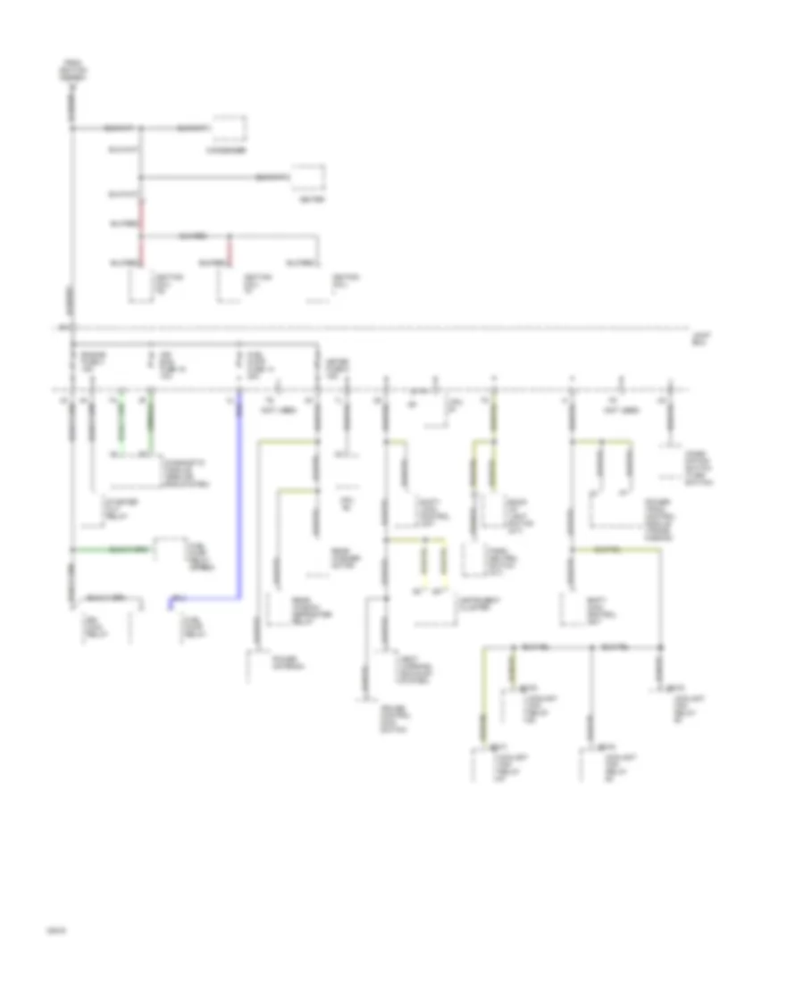
Power Distribution Wiring Diagram (3 of 3) for Mazda RX-7 1994
 https://portal-diagnostov.com/license.html
Automotive Electricians Portal FZCO
Automotive Electricians Portal FZCO
https://portal-diagnostov.com/license.html
https://portal-diagnostov.com/license.html
Automotive Electricians Portal FZCO
Automotive Electricians Portal FZCOList of elements for Power Distribution Wiring Diagram (3 of 3) for Mazda RX-7 1994:
- (not used)
- Air bag fuse 15 10a
- B2-01
- B2-02
- B2-03
- B2-04
- Back- up light switch (m/t)
- Combi- nation switch (turn switch)
- Condenser
- Coolant fan relay #1
- Coolant fan relay #2
- Coolant fan relay #3
- Coolant fan relay #4
- Cpu #1
- Cpu #2
- Cruise control main switch
- Diagnostic module (srs air bag system)
- Egi main relay
- Engine fuse 4 15a
- From ignition switch
- Fuel pump fuse 14 20a
- Fuel pump relay
- Fuel pump relay (speed)
- Heat warning (exhaust system)
- Igniter
- Ignition coil- l
- Ignition coil- tf
- Ignition coil- tr
- Instrument cluster
- Joint box
- Meter fuse 9 15a
- Park/ neutral switch (a/t)
- Power antenna
- Power- train control module (trans- mission)
- Rear washer motor
- Rear window defroster relay
- Shift- lock control unit
- Starter cut relay
POWER DOOR LOCKS
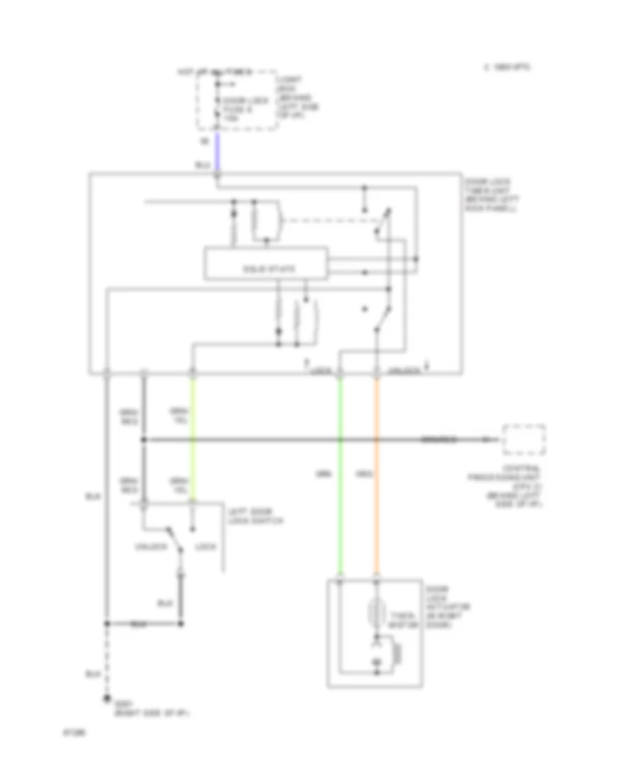
Power Door Lock Wiring Diagram for Mazda RX-7 1994
 https://portal-diagnostov.com/license.html
Automotive Electricians Portal FZCO
Automotive Electricians Portal FZCO
https://portal-diagnostov.com/license.html
https://portal-diagnostov.com/license.html
Automotive Electricians Portal FZCO
Automotive Electricians Portal FZCOList of elements for Power Door Lock Wiring Diagram for Mazda RX-7 1994:
- C 1995 vftc
- Central processing unit (cpu 2) (behind left side of i/p)
- Door lock actuator (in right door)
- Door lock fuse 6 10a
- Door lock timer unit (behind left kick panel)
- G201 (right side of i/p)
- Hot at all times
- Joint box (behind left side of i/p)
- Left door lock switch
- Lock
- Solid state
- Ther- mistor
- Unlock
POWER MIRRORS
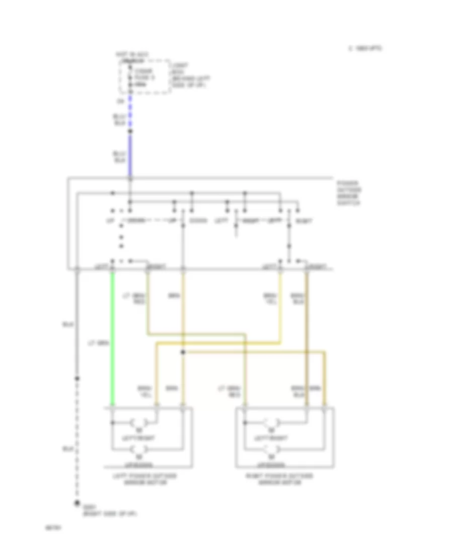
Power Mirror Wiring Diagram for Mazda RX-7 1994
 https://portal-diagnostov.com/license.html
Automotive Electricians Portal FZCO
Automotive Electricians Portal FZCO
https://portal-diagnostov.com/license.html
https://portal-diagnostov.com/license.html
Automotive Electricians Portal FZCO
Automotive Electricians Portal FZCOList of elements for Power Mirror Wiring Diagram for Mazda RX-7 1994:
- C 1995 vftc
- Cigar fuse 5 15a
- Down
- G201 (right side of i/p)
- Hot in acc or run
- Joint box (behind left side of i/p)
- Left
- Left power outside mirror motor
- Left/right
- Power outside mirror switch
- Right
- Right power outside mirror motor
- Up/down
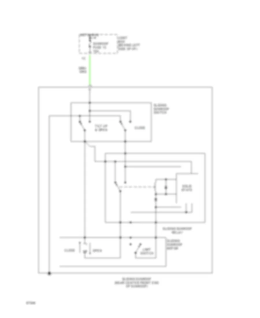
POWER TOP/SUNROOF
Power Top/Sunroof Wiring Diagrams for Mazda RX-7 1994
 https://portal-diagnostov.com/license.html
Automotive Electricians Portal FZCO
Automotive Electricians Portal FZCO
https://portal-diagnostov.com/license.html
https://portal-diagnostov.com/license.html
Automotive Electricians Portal FZCO
Automotive Electricians Portal FZCOList of elements for Power Top/Sunroof Wiring Diagrams for Mazda RX-7 1994:
- Close
- Hot in run
- Joint box (behind left side of i/p)
- Limit switch
- Open
- Sliding sunroof (near center front end of sunroof)
- Sliding sunroof motor
- Sliding sunroof relay
- Sliding sunroof switch
- Solid state
- Sunroof fuse 13 15a
- Tilt up & open
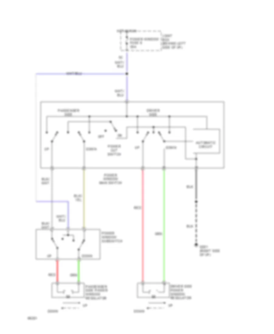
POWER WINDOWS
Power Window Wiring Diagram for Mazda RX-7 1994
 https://portal-diagnostov.com/license.html
Automotive Electricians Portal FZCO
Automotive Electricians Portal FZCO
https://portal-diagnostov.com/license.html
https://portal-diagnostov.com/license.html
Automotive Electricians Portal FZCO
Automotive Electricians Portal FZCOList of elements for Power Window Wiring Diagram for Mazda RX-7 1994:
- Automatic circuit
- Down
- Driver side
- Driver side power window regulator
- G201 (right side of i/p)
- Hot in run
- Joint box (behind left side of i/p)
- Off
- Passenger side power window regulator
- Passenger side
- Power cut switch
- Power window fuse 8 30a
- Power window main switch
- Power window subswitch
- Red
RADIO
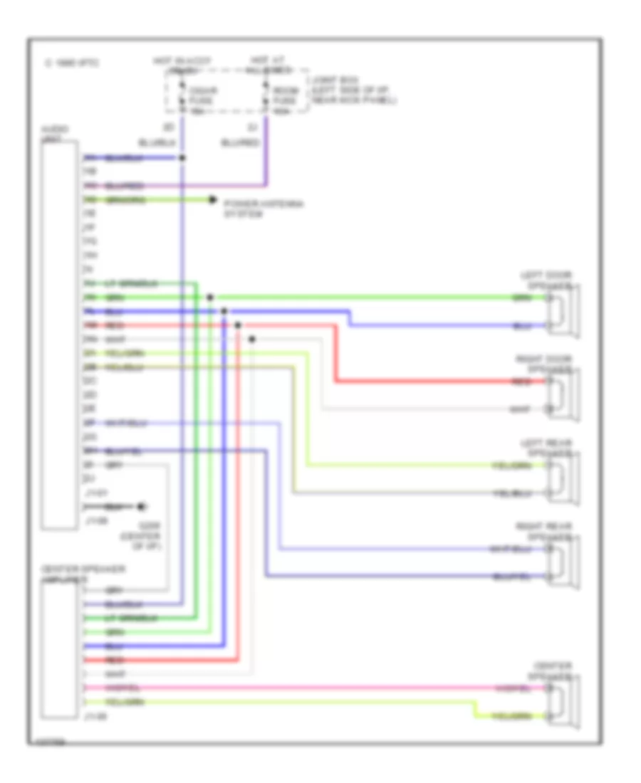
Radio Wiring Diagrams, with Bose Acoustic Wave System for Mazda RX-7 1994
 https://portal-diagnostov.com/license.html
Automotive Electricians Portal FZCO
Automotive Electricians Portal FZCO
https://portal-diagnostov.com/license.html
https://portal-diagnostov.com/license.html
Automotive Electricians Portal FZCO
Automotive Electricians Portal FZCOList of elements for Radio Wiring Diagrams, with Bose Acoustic Wave System for Mazda RX-7 1994:
- 1995 vftc c
- Acoustic wave guide assembly (left rear of trunk)
- Audio fuse 30a
- Audio unit
- Center speaker
- Center speaker amplifier (behind center console)
- Cigar fuse 15a
- G109
- G202 (left side of dash)
- G206 (center of i/p)
- Hot at all times
- Hot in accy or on
- J2-01
- J2-06
- J2-08
- Jc-08 (left side of dash)
- Joint box (left side of i/p, near kick panel)
- Joint connector (right radiator support)
- Left door speaker/ amp module
- Power antenna system
- Radio relay (on right front of engine compartment, on relay block)
- Red
- Relay & fuse block (left side of engine compartment)
- Right door speaker/ amp module
- Room fuse 10a
Radio Wiring Diagrams, without Bose Acoustic Wave System for Mazda RX-7 1994
 https://portal-diagnostov.com/license.html
Automotive Electricians Portal FZCO
Automotive Electricians Portal FZCO
https://portal-diagnostov.com/license.html
https://portal-diagnostov.com/license.html
Automotive Electricians Portal FZCO
Automotive Electricians Portal FZCOList of elements for Radio Wiring Diagrams, without Bose Acoustic Wave System for Mazda RX-7 1994:
- 1995 vftc c
- Audio unit
- Center speaker
- Center speaker amplifier
- Cigar fuse 15a
- G206 (center of i/p)
- Hot at all times
- Hot in accy or on
- J1-01
- J1-06
- J1-08
- Joint box (left side of i/p, near kick panel)
- Left door speaker
- Left rear speaker
- Power antenna system
- Red
- Right door speaker
- Right rear speaker
- Room fuse 10a
SHIFT INTERLOCKS
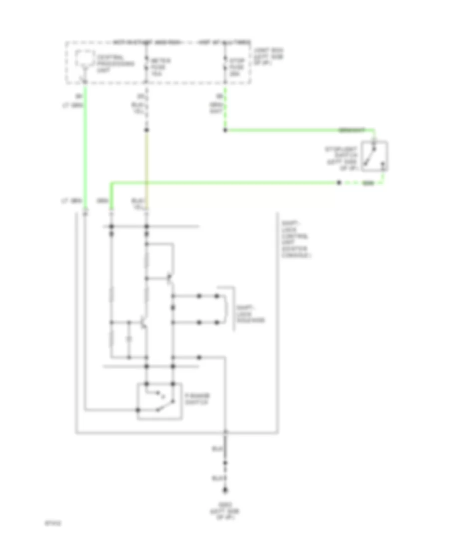
Shift Interlock Wiring Diagram for Mazda RX-7 1994
 https://portal-diagnostov.com/license.html
Automotive Electricians Portal FZCO
Automotive Electricians Portal FZCO
https://portal-diagnostov.com/license.html
https://portal-diagnostov.com/license.html
Automotive Electricians Portal FZCO
Automotive Electricians Portal FZCOList of elements for Shift Interlock Wiring Diagram for Mazda RX-7 1994:
- Central processing unit
- G202 (left side of i/p)
- Hot at all times
- Hot in start and run
- Joint box (left side of i/p)
- Meter fuse 15a
- P-range switch
- Shift- lock control unit (center console)
- Shift- lock solenoid
- Stop fuse 20a
- Stoplight switch (left side of i/p)
STARTING/CHARGING
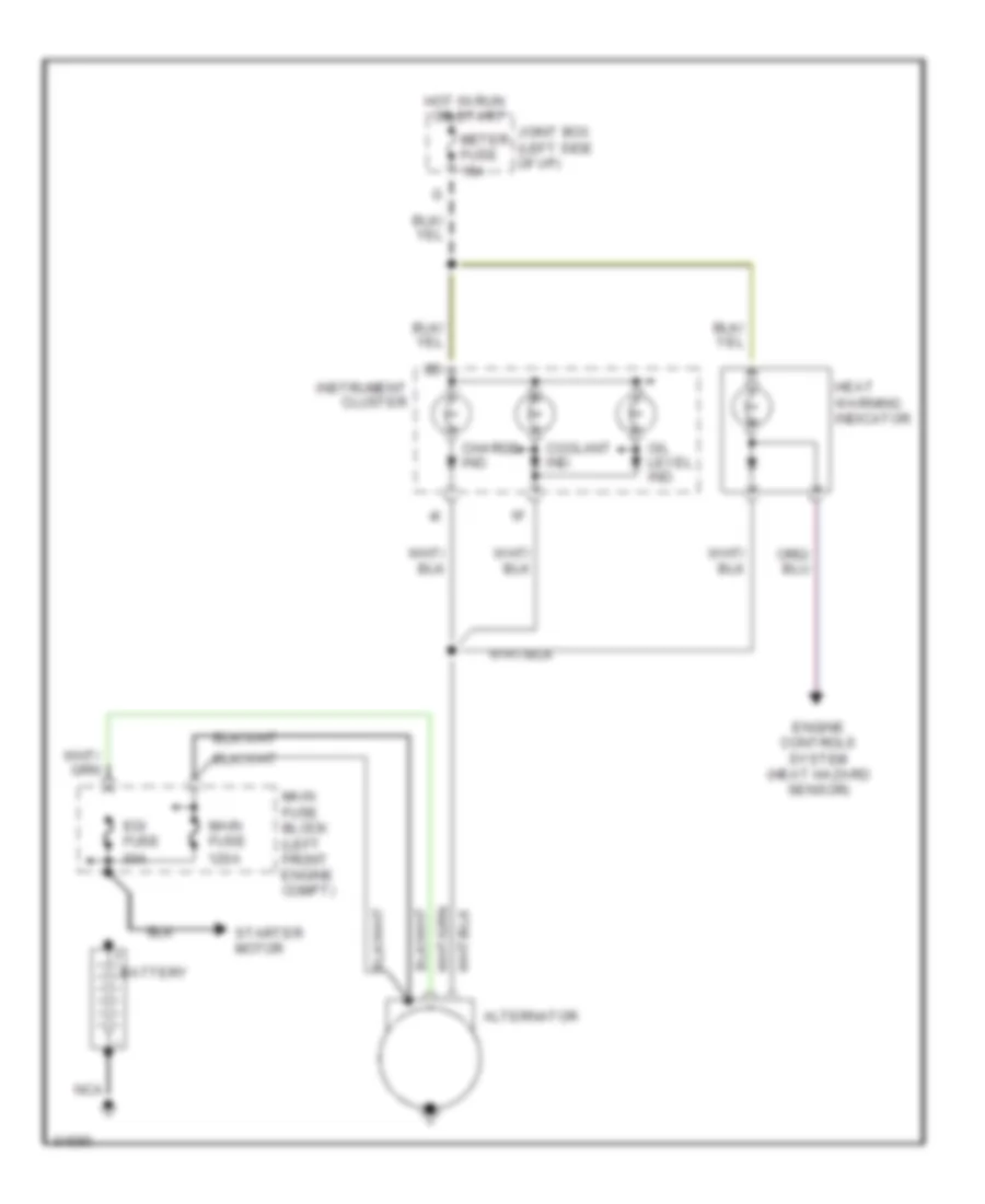
Charging Wiring Diagram for Mazda RX-7 1994
 https://portal-diagnostov.com/license.html
Automotive Electricians Portal FZCO
Automotive Electricians Portal FZCO
https://portal-diagnostov.com/license.html
https://portal-diagnostov.com/license.html
Automotive Electricians Portal FZCO
Automotive Electricians Portal FZCOList of elements for Charging Wiring Diagram for Mazda RX-7 1994:
- Alternator
- Battery
- Charge ind.
- Coolant ind.
- Egi fuse 30a
- Engine controls system (heat hazard sensor)
- Heat warning indicator
- Hot in run
- Instrument cluster
- Joint box (left side of i/p)
- Main fuse 120a
- Main fuse block (left front engine compt)
- Meter fuse 15a
- Nca
- Oil level ind.
- Or start
- Starter motor
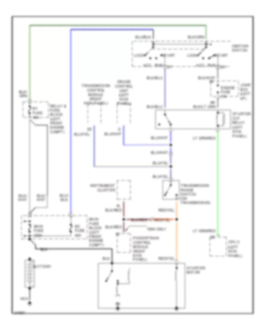
Starting Wiring Diagram, A/T for Mazda RX-7 1994
 https://portal-diagnostov.com/license.html
Automotive Electricians Portal FZCO
Automotive Electricians Portal FZCO
https://portal-diagnostov.com/license.html
https://portal-diagnostov.com/license.html
Automotive Electricians Portal FZCO
Automotive Electricians Portal FZCOList of elements for Starting Wiring Diagram, A/T for Mazda RX-7 1994:
- (left kick panel)
- 1994 only
- Acc
- B1 fuse 40a
- B2 fuse 40a
- Battery
- Cpu 2
- Cruise control unit (left kick panel)
- Engine fuse 15a
- I/p)
- Ig1
- Ignition switch
- Instrument cluster
- Joint box (left
- Lock
- Main fuse 120a
- Main fuse block (left front engine compt)
- Nca
- Powertrain control module (right kick panel)
- Relay & fuse block (left front engine compt)
- Run
- Start
- Starter cut relay
- Starter motor
- Transmission control module (right kick panel)
- Transmission range switch (on transmission)
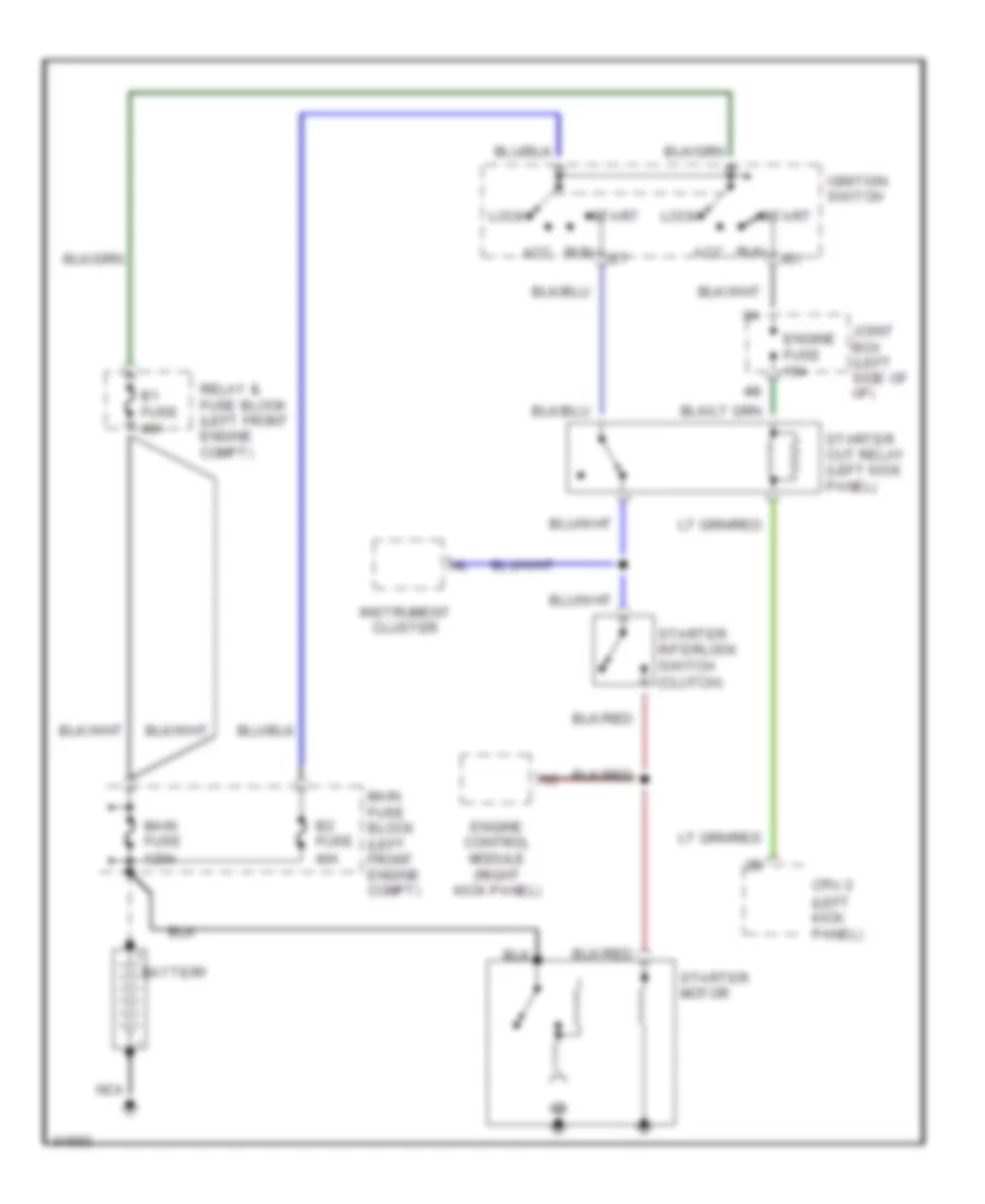
Starting Wiring Diagram, M/T for Mazda RX-7 1994
 https://portal-diagnostov.com/license.html
Automotive Electricians Portal FZCO
Automotive Electricians Portal FZCO
https://portal-diagnostov.com/license.html
https://portal-diagnostov.com/license.html
Automotive Electricians Portal FZCO
Automotive Electricians Portal FZCOList of elements for Starting Wiring Diagram, M/T for Mazda RX-7 1994:
- (left kick panel)
- Acc
- B1 fuse 40a
- B2 fuse 40a
- Battery
- Cpu 2
- Engine control module (right kick panel)
- Engine fuse 15a
- Ig1
- Ignition switch
- Instrument cluster
- Joint box (left side of i/p)
- Lock
- Main fuse 120a
- Main fuse block (left front engine compt)
- Nca
- Relay & fuse block (left front engine compt)
- Run
- Start
- Starter cut relay (left kick panel)
- Starter interlock switch (clutch)
- Starter motor
SUPPLEMENTAL RESTRAINTS
Supplemental Restraint Wiring Diagram for Mazda RX-7 1994
 https://portal-diagnostov.com/license.html
Automotive Electricians Portal FZCO
Automotive Electricians Portal FZCO
https://portal-diagnostov.com/license.html
https://portal-diagnostov.com/license.html
Automotive Electricians Portal FZCO
Automotive Electricians Portal FZCOList of elements for Supplemental Restraint Wiring Diagram for Mazda RX-7 1994:
- Air bag fuse 10a
- Air bag ind
- Center d-sensor (center rear of engine compartment)
- Data link connector (left rear of engine compartment)
- Diagnostic module (left side of i/p)
- Engine fuse 15a
- Fuse inj fuse 30a
- G201 (right side of i/p)
- G202 (left side of i/p)
- Hazard fuse 15a
- Horn relay (front of engine compartment)
- Horn system
- Hot at all times
- Hot in run and start
- Instrument cluster
- Joint box (left side of i/p)
- Left air bag module (steering column)
- Left d-sensor (left side of engine compartment)
- Main fuse block (left side of engine compartment)
- Meter fuse 15a
- Nca
- Pnk
- Red
- Right air bag module (right side of dash)
- Right d-sensor (right side of engine compartment)
- S-sensor (below center of i/p)
- Solid state
TRANSMISSION
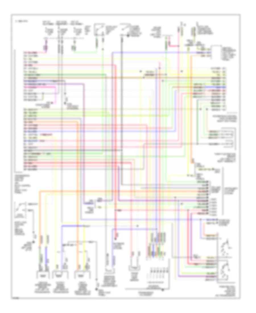
Transmission Wiring Diagram for Mazda RX-7 1994
 https://portal-diagnostov.com/license.html
Automotive Electricians Portal FZCO
Automotive Electricians Portal FZCO
https://portal-diagnostov.com/license.html
https://portal-diagnostov.com/license.html
Automotive Electricians Portal FZCO
Automotive Electricians Portal FZCOList of elements for Transmission Wiring Diagram for Mazda RX-7 1994:
- (or)
- 1994 & models
- 1995 vftc c
- Air conditioning system
- Central processing unit no. 2 (anti-theft) (left kick panel)
- Cpu and speedo- meter
- Cruise control unit (left kick panel)
- D indic
- Data link connector (left engine compartment)
- Dropping resistor (right side of engine compartment)
- Ec-at control unit (right kick panel)
- Exterior lights system
- Fat
- G202 behind left side of i/p)
- G203 (right kick panel)
- Hold indic
- Hold switch
- Hot at all times
- Hot in on or start
- I/p)
- Ig-
- Input/ turbine speed sensor (front left of transmission)
- Instrument cluster system
- Joint box (left
- L indic
- Meter fuse 15a
- Models
- N indic
- N0. 1
- N0. 2
- N0. 3
- N0. 4
- N0. 5
- N0. 6
- Nca
- Output speed sensor (left rear of
- P indic
- Park/neutral switch (inhibitor switch) (on transmission)
- Pnk
- Powertrain control module (engine) (right kick panel)
- R indic
- Red
- Room fuse 10a
- S indic
- Shift-lock control unit (below center console)
- Solenoid valve (ec-at)
- Starting/ charging system
- Stop fuse 20a
- Stoplight switch (left i/p)
- Throttle position sensor (on throttle body assembly)
- Trans fluid temp sensor
- Transmission control module
- Transmission valve body
- Transmission)
- Vehicle speedometer sensor (top left of
- Water thermo- switch (front of engine)
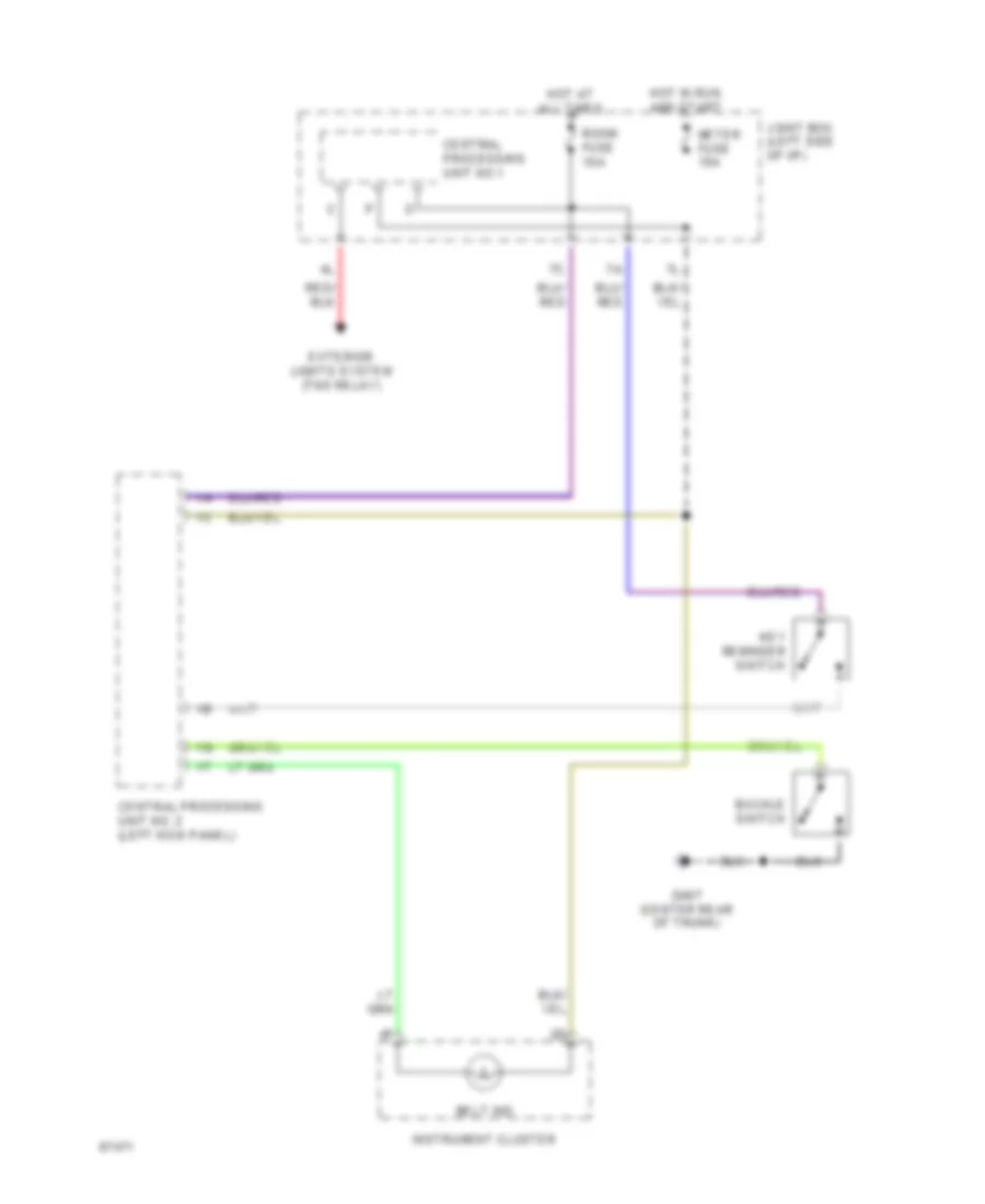
WARNING SYSTEMS
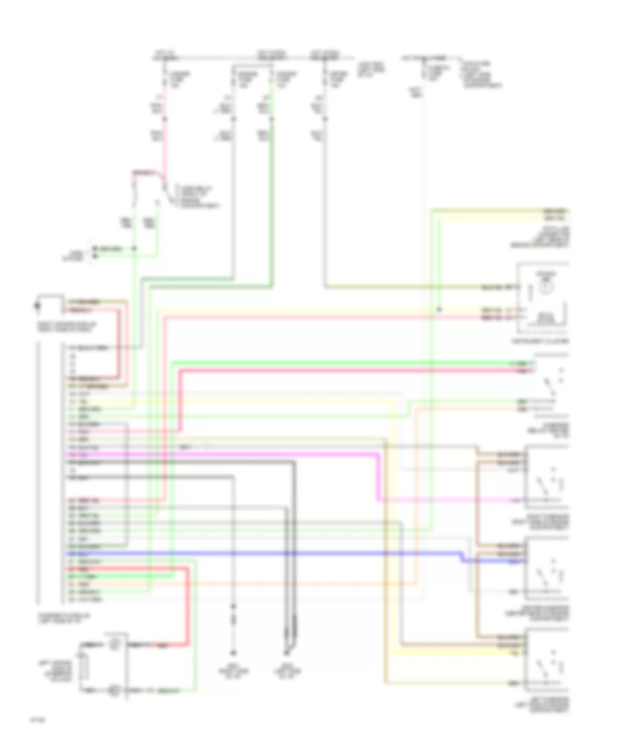
Warning System Wiring Diagrams for Mazda RX-7 1994
 https://portal-diagnostov.com/license.html
Automotive Electricians Portal FZCO
Automotive Electricians Portal FZCO
https://portal-diagnostov.com/license.html
https://portal-diagnostov.com/license.html
Automotive Electricians Portal FZCO
Automotive Electricians Portal FZCOList of elements for Warning System Wiring Diagrams for Mazda RX-7 1994:
- Belt ind
- Buckle switch
- Central processing unit no. 2 (left kick panel)
- Central processing unit no.1
- Exterior lights system (tns relay)
- G407 (center rear of trunk)
- Hot at all times
- Hot in run and start
- Instrument cluster
- Joint box (left side of i/p)
- Key reminder switch
- Meter fuse 15a
- Room fuse 10a
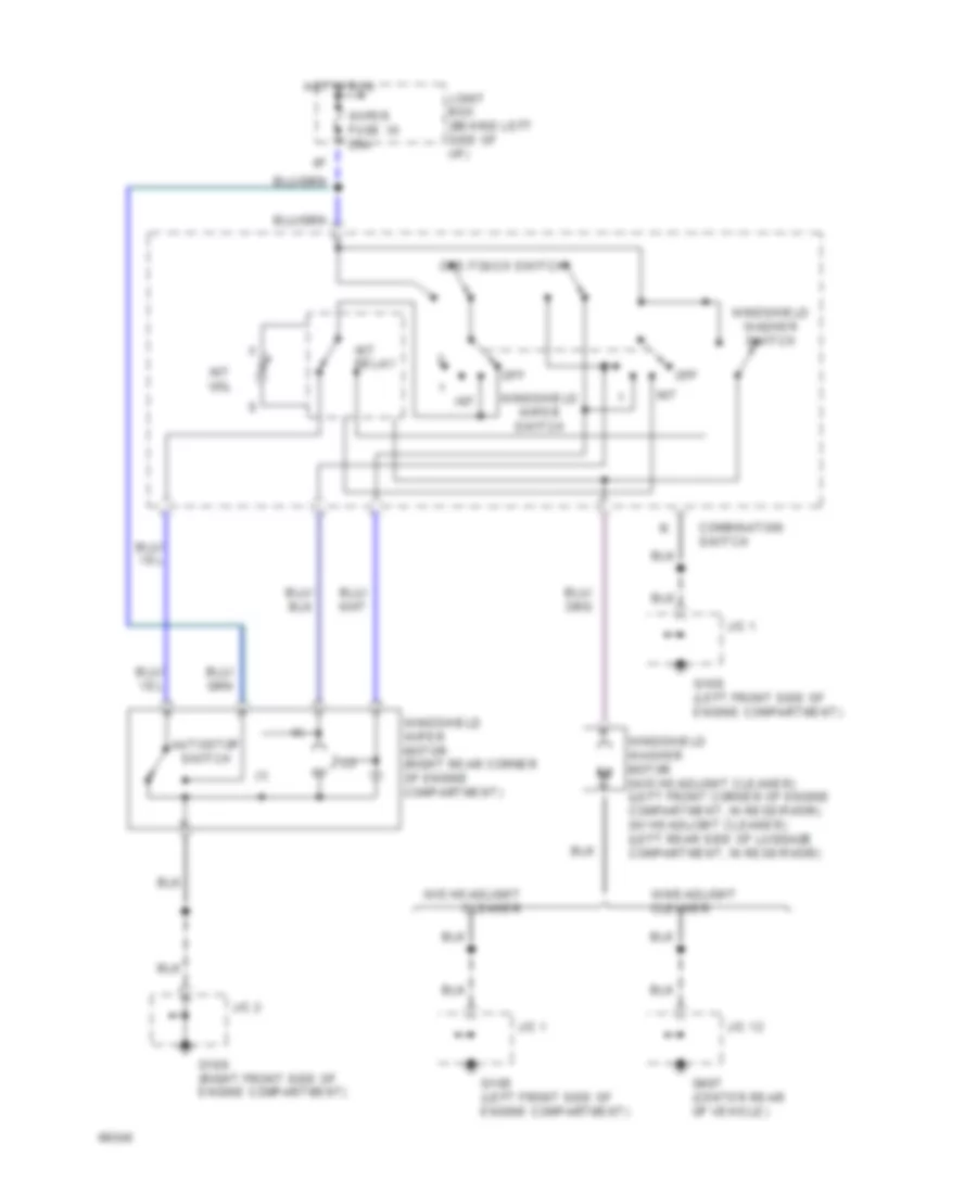
WIPER/WASHER
Front Wiper/Washer Wiring Diagram for Mazda RX-7 1994
 https://portal-diagnostov.com/license.html
Automotive Electricians Portal FZCO
Automotive Electricians Portal FZCO
https://portal-diagnostov.com/license.html
https://portal-diagnostov.com/license.html
Automotive Electricians Portal FZCO
Automotive Electricians Portal FZCOList of elements for Front Wiper/Washer Wiring Diagram for Mazda RX-7 1994:
- Autostop switch
- Combination switch
- G108 (left front side of engine compartment)
- G109 (right front side of engine compartment)
- G407 (center rear of vehicle)
- Hot in run
- Int
- Int relay
- Int vol
- J/c 1
- J/c 12
- J/c 2
- Joint box (behind left side of i/p)
- Off
- One-touch switch
- W/headlight cleaner
- W/o headlight cleaner
- Windshield washer motor (w/o headlight cleaner) (left front corner of engine compartment, in reservoir) (w/ headlight cleaner) (left rear side of luggage compartment, in reservoir)
- Windshield washer switch
- Windshield wiper motor (right rear corner of engine compartment)
- Windshield wiper switch
- Wiper fuse 10 20a
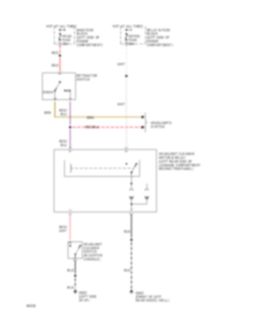
Headlamp Washer Wiring Diagram for Mazda RX-7 1994
 https://portal-diagnostov.com/license.html
Automotive Electricians Portal FZCO
Automotive Electricians Portal FZCO
https://portal-diagnostov.com/license.html
https://portal-diagnostov.com/license.html
Automotive Electricians Portal FZCO
Automotive Electricians Portal FZCOList of elements for Headlamp Washer Wiring Diagram for Mazda RX-7 1994:
- Defog fuse 60a
- Down
- G202 (left side of i/p)
- G402 (front of left rear wheel well)
- Head fuse 30a
- Headlight cleaner motor & relay (left rear side of luggage compartment behind trim panel)
- Headlight cleaner switch (in center console)
- Headlights system
- Hot at all times
- Main fuse block (left side of engine compartment)
- Red
- Relay & fuse block (left side of engine compartment)
- Retractor switch
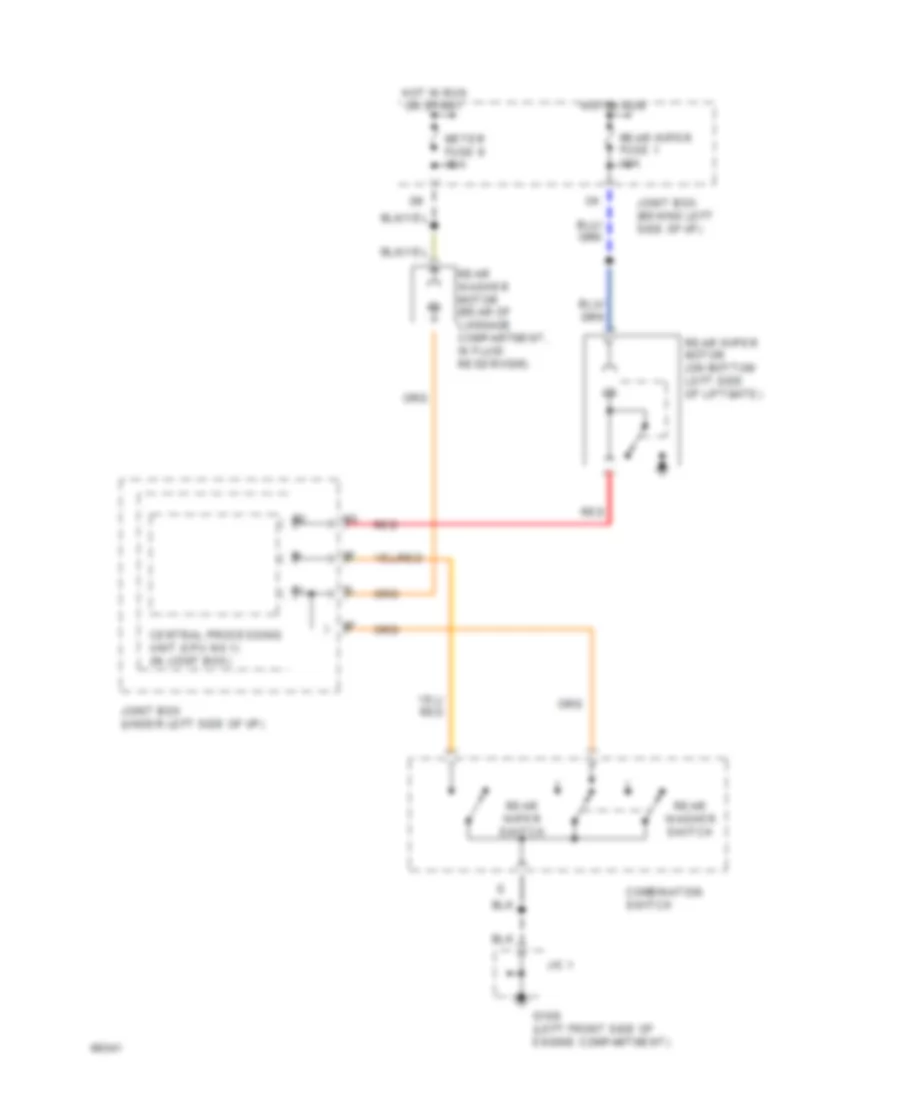
Rear Wiper/Washer Wiring Diagram for Mazda RX-7 1994
 https://portal-diagnostov.com/license.html
Automotive Electricians Portal FZCO
Automotive Electricians Portal FZCO
https://portal-diagnostov.com/license.html
https://portal-diagnostov.com/license.html
Automotive Electricians Portal FZCO
Automotive Electricians Portal FZCOList of elements for Rear Wiper/Washer Wiring Diagram for Mazda RX-7 1994:
- Central processing unit (cpu no.1) (in joint box)
- Combination switch
- G108 (left front side of engine compartment)
- Hot in run
- Hot in run or start
- J/c 1
- Joint box (behind left side of i/p)
- Joint box (under left side of i/p)
- Meter fuse 9 15a
- Rear washer motor (rear of luggage compartment, in fluid reservoir)
- Rear washer switch
- Rear wiper fuse 1 10a
- Rear wiper motor (on bottom left side of liftgate)
- Rear wiper switch
- Red

 Čeština
 Dansk
Dansk Deutsch
 Ελληνικά
 English
 English
 Español
 Suomi
Suomi Français
 Français
 עברית
עברית Hrvatski
 Magyar
 Italiano
 日本語
日本語 Nederlands
 Polski
 Português
 Português
 Română
 Русский
 Slovenčina
 Slovenščina
 Svenska
 Türkçe
 中文 (中国)
