AIR CONDITIONING
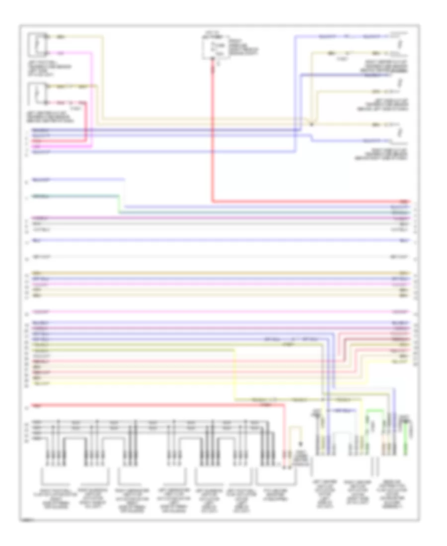
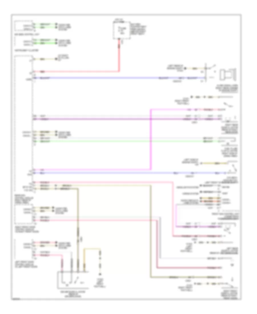
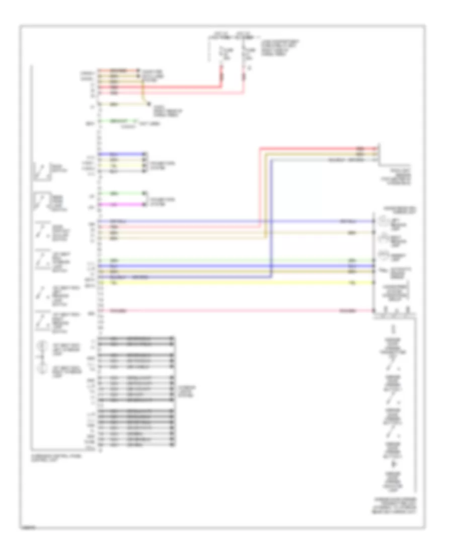
Automatic A/C Wiring Diagram, with Thermotronic (1 of 4) for Mercedes-Benz GL350 2012
 https://portal-diagnostov.com/license.html
Automotive Electricians Portal FZCO
Automotive Electricians Portal FZCO
https://portal-diagnostov.com/license.html
https://portal-diagnostov.com/license.html
Automotive Electricians Portal FZCO
Automotive Electricians Portal FZCO
List of elements for Automatic A/C Wiring Diagram, with Thermotronic (1 of 4) for Mercedes-Benz GL350 2012:
- (+)
- (behind right kick panel) w29/2
- (not used)
- (not used) x122/3-c1
- (not used) x18
- 3.0l turbo
- A/c air recirculation unit
- Air recirculation switch
- Anst
- Battery compartment prefuse box (behind right front seat)
- Blower motor
- Blower regulator
- Booster blower electronic blower controller (on booster blower motor)
- Booster blower motor (under rear of center console)
- C10a
- C12a
- C78
- C91
- Can-b h
- Can-b l
- Center rear interior temperature sensor (under rear of center console)
- Cockpit fuse box (behind right end of dash)
- Comfort aac (kla) control & operating unit
- Computer data lines system
- Coolant circulation pump (in left front wheelwell)
- Dew point sensor (under right side of dash)
- Diag
- Except 3.0l turbo
- Fresh air & air recirculation flap actuator motor (right side of fresh air housing)
- Fuse 10a
- Fuse 150a
- Fuse 15a
- Fuse 40a
- Gnd
- Hot at all times
- Krv
- Lin
- Nca
- Pnk
- Red
- Refrigerant compressor
- Sig
- W/ heated windshield
- W29/2 (behind right kick panel)
- W9 (left side of engine compt)
- Wake up
- X122/2-c1
- X122/2-c2
- X122/4
- X18
- X18-c2
- X18/7
- X25/2-c1
- X25/2-c2
- X25/2-c2 d7
- X26-c2
- Zwp
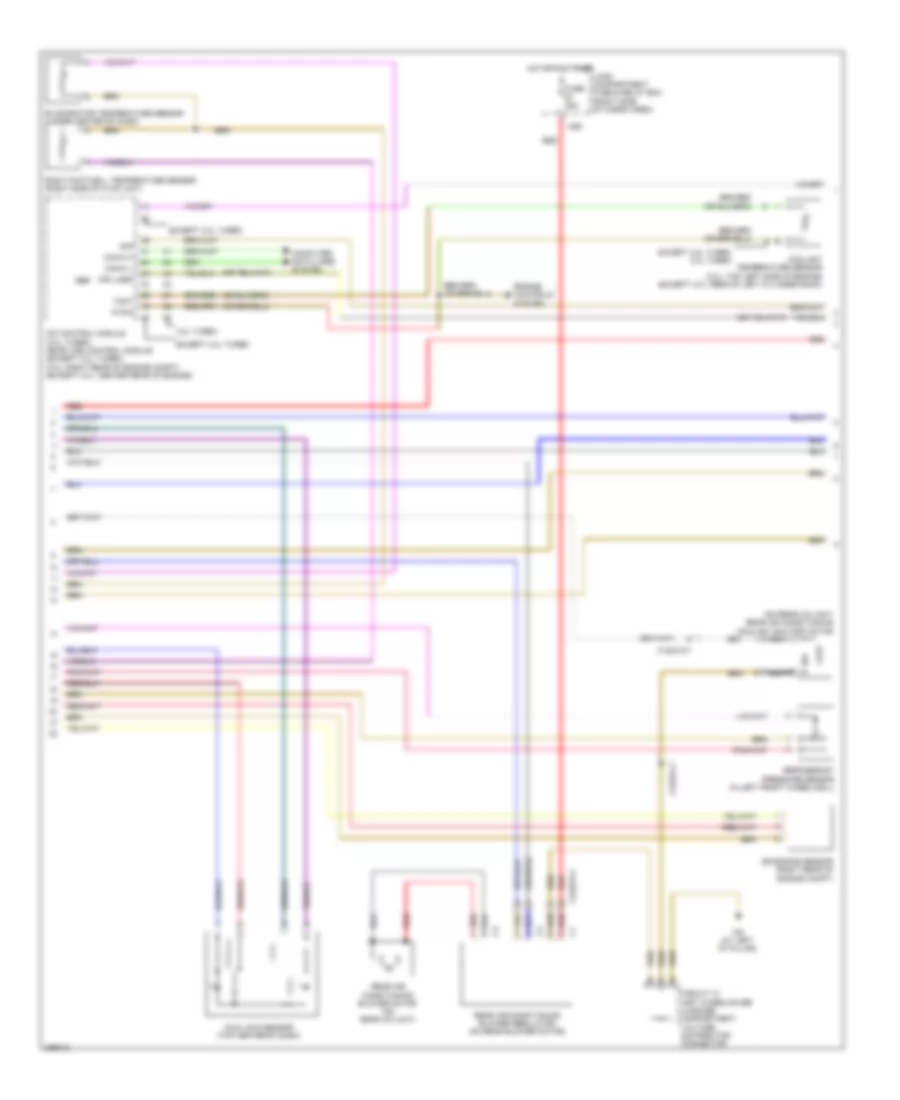
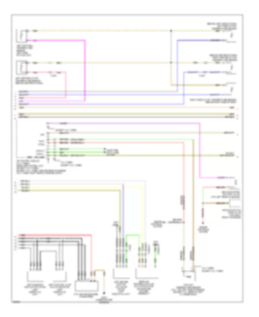
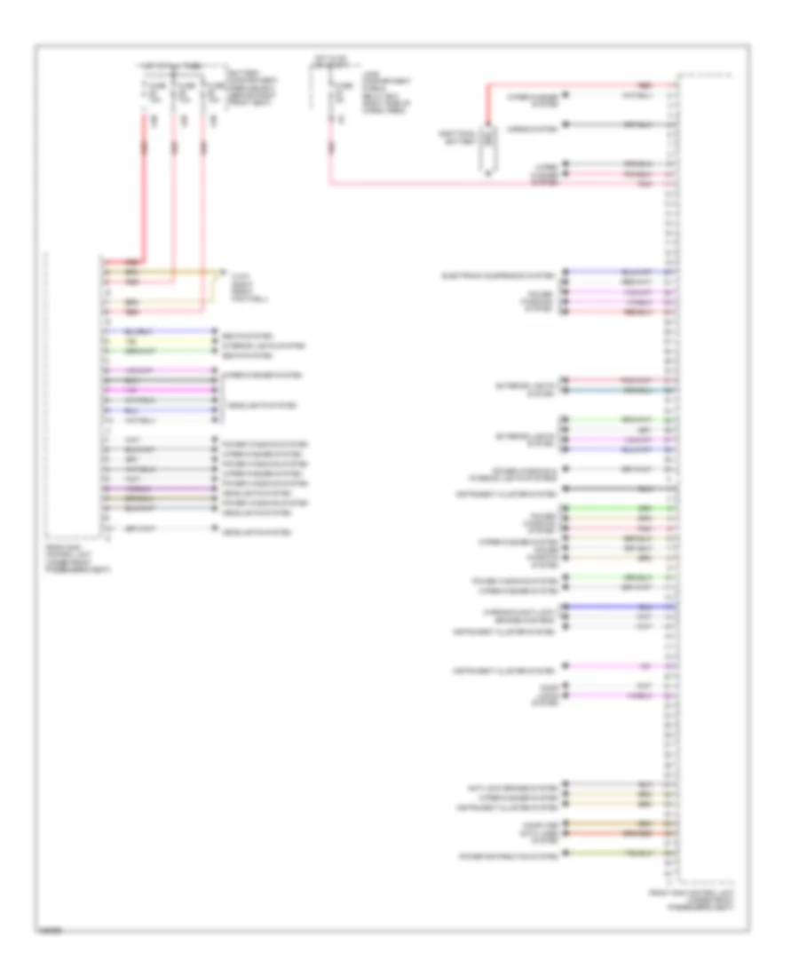
Automatic A/C Wiring Diagram, with Thermotronic (2 of 4) for Mercedes-Benz GL350 2012
 https://portal-diagnostov.com/license.html
Automotive Electricians Portal FZCO
Automotive Electricians Portal FZCO
https://portal-diagnostov.com/license.html
https://portal-diagnostov.com/license.html
Automotive Electricians Portal FZCO
Automotive Electricians Portal FZCOList of elements for Automatic A/C Wiring Diagram, with Thermotronic (2 of 4) for Mercedes-Benz GL350 2012:
- (not used)
- (not used) x122/1
- Front prefuse (right rear of engine compt)
- Fuse 100a
- Hot at all times
- Left blending air flap actuator (left side of a/c unit)
- Left center air flap actuator motor (left side of a/c unit)
- Left center outlet temperature sensor (behind center of dash)
- Left defroster vent flap actuator motor (left side of fresh air housing)
- Left footwell flap actuator motor (left side of a/c unit)
- Left footwell temperature sensor (left side of hvac unit)
- Left side outlet temperature sensor (behind left side of dash)
- Nca
- Pnk
- Ptc heater booster (if equipped)
- Rear air distribution flap actuator motor (on booster blower assembly)
- Red
- Right blending air flap actuator (right side of a/c unit)
- Right center air flap actuator motor (right side of a/c unit)
- Right center outlet temperature sensor (behind center of dash)
- Right defroster vent flap actuator motor (right side of fresh air housing)
- Right footwell flap actuator motor (right side of fresh air housing)
- Right side outlet temperature sensor (behind right side of dash)
- W52/7 (under center console)
- X122/1
- X122/2-c1
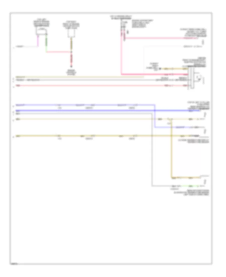
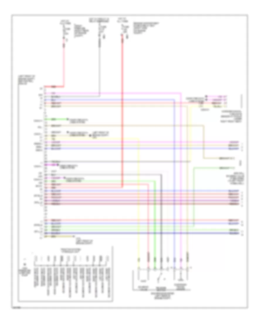
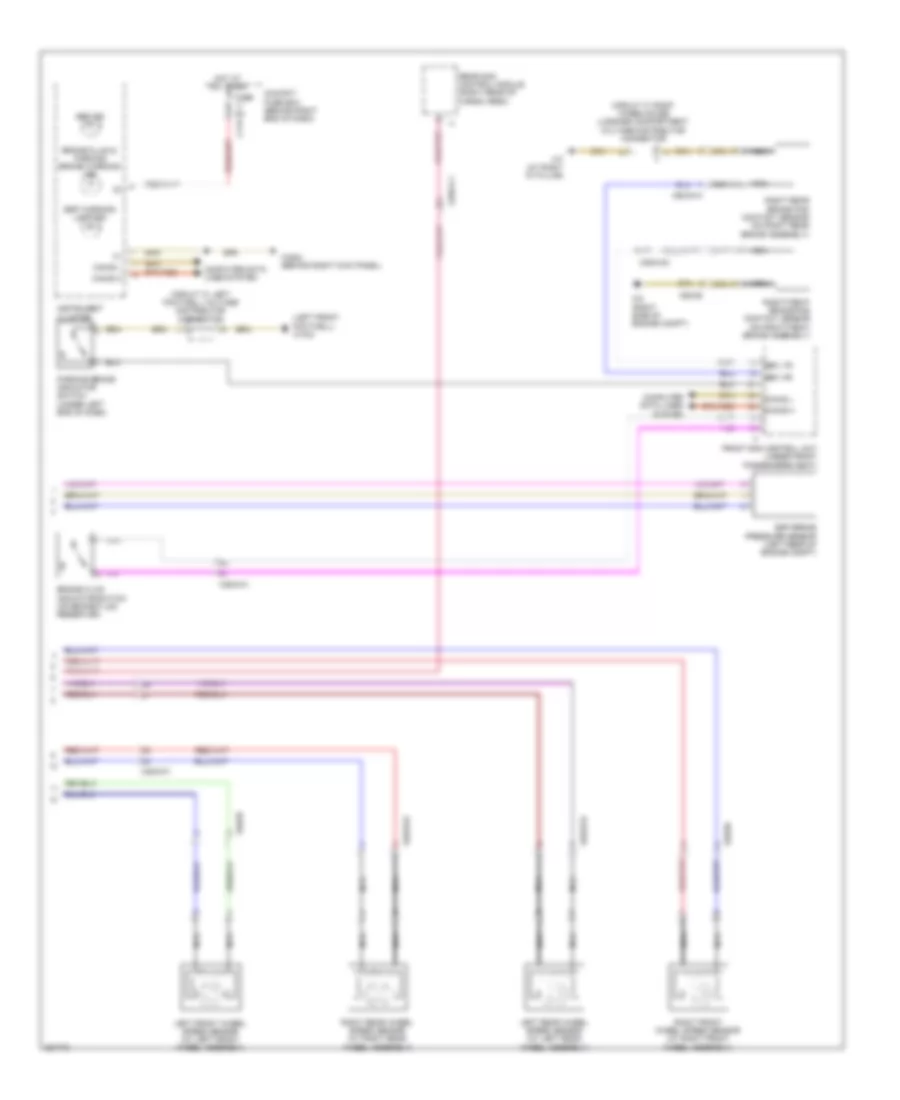
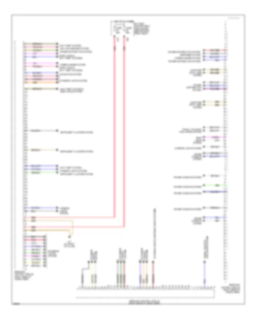
Automatic A/C Wiring Diagram, with Thermotronic (3 of 4) for Mercedes-Benz GL350 2012
 https://portal-diagnostov.com/license.html
Automotive Electricians Portal FZCO
Automotive Electricians Portal FZCO
https://portal-diagnostov.com/license.html
https://portal-diagnostov.com/license.html
Automotive Electricians Portal FZCO
Automotive Electricians Portal FZCOList of elements for Automatic A/C Wiring Diagram, with Thermotronic (3 of 4) for Mercedes-Benz GL350 2012:
- (on rear a/c unit) rear air conditioning coolant shutoff motor
- (or lues)
- 3.0l turbo
- Akf
- Can-c h
- Can-c l
- Cdi control module (3.0l turbo) me-sfi (me) control module (except 3.0l turbo) (3.0l: right rear of engine compt) (except 3.0l: center rear of engine)
- Circuit 31 left wheelhouse luggage compartment voltage distributor connector
- Computer data lines system
- Coolant temperature sensor (3.0l: top left side of engine) (except 3.0l: rear of left cylinder bank)
- Dual sun sensor (top center of dash)
- Emissions sensor (right rear of engine compt)
- Engine controls system
- Evaporator temperature sensor (under center of dash)
- Except 3.0l turbo
- Fuse 25a
- Ger
- Hot at all times
- Kts-s
- Load compartment fuse & relay box (right side of cargo area)
- Ms2
- Nca
- Rear air conditioning blower motor (on rear a/c unit)
- Rear air conditioning blower regulator (on rear blower motor)
- Red
- Refrigerant pressure sensor (in left front wheelwell)
- Right footwell temperature sensor (right side of hvac unit)
- Tmot
- W6 (at left "d" pillar)
- X122/3-c1
- X122/3-c2
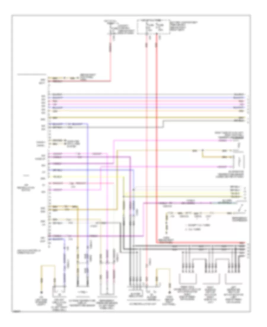
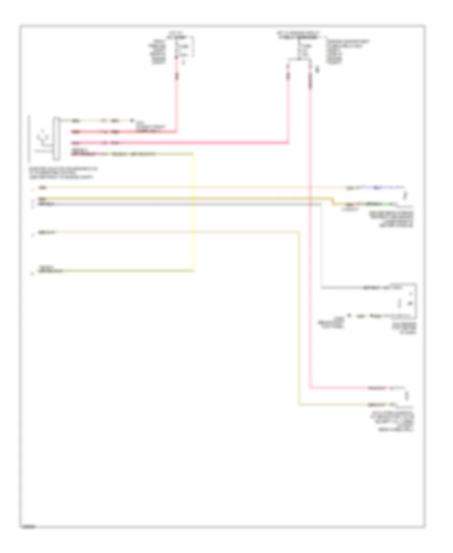
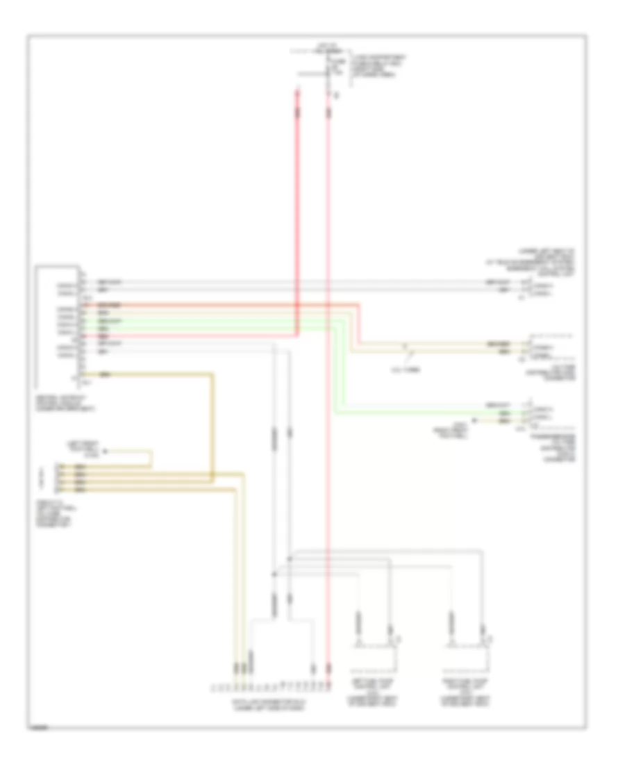
Automatic A/C Wiring Diagram, with Thermotronic (4 of 4) for Mercedes-Benz GL350 2012
 https://portal-diagnostov.com/license.html
Automotive Electricians Portal FZCO
Automotive Electricians Portal FZCO
https://portal-diagnostov.com/license.html
https://portal-diagnostov.com/license.html
Automotive Electricians Portal FZCO
Automotive Electricians Portal FZCOList of elements for Automatic A/C Wiring Diagram, with Thermotronic (4 of 4) for Mercedes-Benz GL350 2012:
- (center front of engine compt) electric suction fan engine & a/c w/ integrated control
- (in right front wheelwell) w2/1
- (in right rear wheelwell) (except 3.0l turbo) activated charcoal filter shutoff valve
- (top left rear of engine) heating system shutoff valve
- (top of left "c" pillar) (if equipped) rear headroom a/c temperature sensor
- (top right front of engine) air pump switch over valve
- Engine compartment fuse & relay box (right side of engine compt)
- Engine controls system
- Fuse 15a
- Hot w/ engine circuit 87 relay energized
- Mr1
- Nca
- Outside temperature display temperature sensor
- Pnk
- Rear air conditioning evaporator temperature sensor (left side of cargo area)
- Red
- X122/3-c1
- X18
- X25/2-c1
- X26/32
Automatic A/C Wiring Diagram, without Thermotronic (1 of 3) for Mercedes-Benz GL350 2012
 https://portal-diagnostov.com/license.html
Automotive Electricians Portal FZCO
Automotive Electricians Portal FZCO
https://portal-diagnostov.com/license.html
https://portal-diagnostov.com/license.html
Automotive Electricians Portal FZCO
Automotive Electricians Portal FZCOList of elements for Automatic A/C Wiring Diagram, without Thermotronic (1 of 3) for Mercedes-Benz GL350 2012:
- (behind right kick panel) w29/2
- (right side of hvac unit) right footwell temperature sensor
- 3.0l turbo
- A/c recirculation unit
- Aac (kla) control & operating unit
- Air recirculation switch
- Batt
- Battery compartment prefuse box (behind right front seat)
- Blower motor
- Blower regulator
- C12a
- C78
- C91
- Can-b h
- Can-b l
- Cockpit fuse box (behind right end of dash)
- Computer data lines system
- Coolant circulation pump (in left front wheelwell)
- Evaporator temperature sensor (under center of dash)
- Except 3.0l turbo
- Fresh air & air recirculation flap actuator motor (right side of fresh air housing)
- Fuse 150a
- Fuse 15a
- Fuse 40a
- Gnd
- Hot at all times
- Krv
- Left defroster vent flap actuator motor (left side of fresh air housing)
- Lin
- Nca
- Outside temperature display temperature sensor
- Pnk
- Red
- Refrigerant compressor
- Refrigerant pressure sensor (in left front wheelwell)
- Right blending air flap actuator (right side of a/c unit)
- Sig
- W29/2 (behind right kick panel)
- W9 (left side of engine compt)
- Wake up
- X122/4
- X18
- X18-c2
- X18/7
- X25/2-c1
- X25/2-c2
- X26-c2
- X26/32
- Zwp
Automatic A/C Wiring Diagram, without Thermotronic (2 of 3) for Mercedes-Benz GL350 2012
 https://portal-diagnostov.com/license.html
Automotive Electricians Portal FZCO
Automotive Electricians Portal FZCO
https://portal-diagnostov.com/license.html
https://portal-diagnostov.com/license.html
Automotive Electricians Portal FZCO
Automotive Electricians Portal FZCOList of elements for Automatic A/C Wiring Diagram, without Thermotronic (2 of 3) for Mercedes-Benz GL350 2012:
- (behind center of dash) right center outlet temperature sensor
- (behind left side of dash) left side outlet temperature sensor
- (not used)
- (not used) x122/4
- (or lues)
- 3.0l turbo
- Air pump switch over valve (top right front of engine)
- Akf
- Can-c h
- Can-c l
- Cdi control module (3.0l turbo) me-sfi (me) control unit (except 3.0l turbo) (except 3.0l turbo: center rear of engine) (3.0l turbo: right rear of engine compt)
- Computer data lines system
- Coolant temperature sensor (3.0l: top left side of engine) (except 3.0l: rear of left cylinder bank)
- Engine controls system
- Except 3.0l turbo
- Ger
- Heating system shutoff valve (top left rear of engine)
- Kts-s
- Left blending air flap actuator (left side of a/c unit)
- Left center air flap actuator motor (left side of a/c unit)
- Left center outlet temperature sensor (behind center of dash)
- Left footwell flap actuator motor (left side of a/c unit)
- Left footwell temperature sensor (left side of hvac unit)
- Nca
- Pnk
- Ptc heater booster (if equipped)
- Rear air distribution flap actuator motor (on booster blower assembly)
- Red
- Right side outlet temperature sensor (behind right side of dash)
- Tmot
- W52/7 (under center console)
- X122/1
- X122/2-c1
Automatic A/C Wiring Diagram, without Thermotronic (3 of 3) for Mercedes-Benz GL350 2012
 https://portal-diagnostov.com/license.html
Automotive Electricians Portal FZCO
Automotive Electricians Portal FZCO
https://portal-diagnostov.com/license.html
https://portal-diagnostov.com/license.html
Automotive Electricians Portal FZCO
Automotive Electricians Portal FZCOList of elements for Automatic A/C Wiring Diagram, without Thermotronic (3 of 3) for Mercedes-Benz GL350 2012:
- Activated charcoal filter shutoff valve (except 3.0l turbo) (in right rear wheelwell)
- Center rear interior temperature sensor (under rear of center console)
- Electric suction fan engine & a/c w/ integrated control (center front of engine compt)
- Engine compartment fuse & relay box (right side of engine compt)
- Front prefuse (right rear of engine compt)
- Fuse 100a
- Fuse 15a
- Hot at all times
- Hot w/ engine circuit 87 relay energized
- Mr1
- Pnk
- Red
- Sun sensor (top center of dash)
- W2/1 (in right front wheelwell)
- W29/2 (behind right kick panel)
- X122/2-c1
ANTI-LOCK BRAKES
Anti-lock Brakes Wiring Diagram (1 of 2) for Mercedes-Benz GL350 2012
 https://portal-diagnostov.com/license.html
Automotive Electricians Portal FZCO
Automotive Electricians Portal FZCO
https://portal-diagnostov.com/license.html
https://portal-diagnostov.com/license.html
Automotive Electricians Portal FZCO
Automotive Electricians Portal FZCOList of elements for Anti-lock Brakes Wiring Diagram (1 of 2) for Mercedes-Benz GL350 2012:
- (+)
- (-)
- (left front of engine compt) esp control module
- (left front of engine compt) w70
- Ba mv
- Bas brake booster (left rear of engine compt)
- Can-c h
- Can-c l
- Can-h h
- Can-h l
- Computer data lines system
- Dfhl_s
- Dfhr_s
- Dfvl_s
- Dfvr_s
- Diaphragm travel sensor
- Drs s
- Drs(-)
- Drs(5v)
- Engine compartment fuse & relay box (right side of engine compt)
- Front axle inlet solenoid valve
- Front axle switchover solenoid valve
- Front prefuse (right rear of engine compt)
- Fuse 25a
- Fuse 40a
- Fuse 5a
- High pressure & return pump
- Hot at all times
- Hot w/ circuit 15 relay energized
- Left front solenoid valve (hold)
- Left front solenoid valve (release)
- Left rear solenoid valve (release)
- Ls1
- Ls2
- Lsa
- Micromechanical turn rate sensor ay pickup (under right front seat)
- Mr3
- Mr4
- Pml
- Rear axle switchover solenoid valve
- Red
- Release switch
- Right front solenoid valve (release)
- Right rear solenoid valve (release)
- Sig
- Solenoid valve
- Solenoid valve (hold) left rear
- Solenoid valve (hold) right front
- Solenoid valve (hold) right rear
- Solenoid valve rear axle inlet
- Sps (pml) solenoid valve (if equipped) (in left front wheelwell)
- Traction system hydraulic unit
- W70 (left front of engine compt)
- X25/2-c1
Anti-lock Brakes Wiring Diagram (2 of 2) for Mercedes-Benz GL350 2012
 https://portal-diagnostov.com/license.html
Automotive Electricians Portal FZCO
Automotive Electricians Portal FZCO
https://portal-diagnostov.com/license.html
https://portal-diagnostov.com/license.html
Automotive Electricians Portal FZCO
Automotive Electricians Portal FZCOList of elements for Anti-lock Brakes Wiring Diagram (2 of 2) for Mercedes-Benz GL350 2012:
- (left front footwell) w15/2
- (on right front brake assembly)
- Abs ind
- Bbv hr
- Bbv vr
- Brake fluid & parking brake warning ind
- Brake fluid indicator switch (on brake fluid reservoir)
- C11a
- Can-b h
- Can-b l
- Circuit 31 left footwell voltage distributor connector
- Circuit 31 right wheelhouse luggage compartment voltage distributor connector
- Cockpit fuse box (behind right end of dash)
- Computer data lines system
- Esp brake pressure sensor (left rear of engine compt)
- Esp warning lamp ind
- Front sam control unit (under front passenger's seat)
- Fuse 5a
- Hot at all times
- Instrument cluster
- Left front wheel speed sensor (at left front wheel assembly)
- Left rear wheel speed sensor (at left rear wheel assembly)
- Nca
- Parking brake indicator switch (under left end of dash)
- Rear sam control module (right rear of cargo area)
- Right front brake pad contact sensor
- Right front wheel speed sensor (at right front wheel assembly)
- Right rear brake pad contact sensor (on right rear brake assembly)
- Right rear wheel speed sensor (at right rear wheel assembly)
- W2 (right side of engine compt)
- W29/2 (behind right kick panel)
- W7 (at right "d" pillar)
- X25/2-c1
- X25/2-c2
- X62/32-d
- X62/33-a
- X62/33-d
- X62/35
- X62/36
ANTI-THEFT
Anti-theft Wiring Diagram for Mercedes-Benz GL350 2012
 https://portal-diagnostov.com/license.html
Automotive Electricians Portal FZCO
Automotive Electricians Portal FZCO
https://portal-diagnostov.com/license.html
https://portal-diagnostov.com/license.html
Automotive Electricians Portal FZCO
Automotive Electricians Portal FZCOList of elements for Anti-theft Wiring Diagram for Mercedes-Benz GL350 2012:
- (at right "d" pillar) w7
- (left rear of engine compt) w16/3
- (left side of engine compt) w9
- (right side of cargo area)
- 56a re
- Alarm signal horn (right rear corner of engine compt)
- Anst
- Ata (edw) hood switch (left front of engine compt)
- Battery compartment prefuse box (behind right front seat)
- Bf zv df
- C79
- Can b h
- Can b l
- Can-b h
- Can-b l
- Can-c h
- Can-c l
- Computer data lines system
- Driver door cl motor (rear of driver's door)
- Eis (ezs) control unit
- F zv df
- Front sam control unit (under front passenger's seat)
- Fuel filler flap cl motor
- Fuse 60a
- Headlights system
- Horn
- Horns system
- Hot at all times
- Instrument cluster
- Left front door control module (in left front door)
- Left rear door cl motor (rear of left rear door)
- Mhk
- Rear sam control module (right rear of cargo area)
- Red
- Right front door cl motor (rear of right front door)
- Right front door control module (in right front door)
- Right rear door cl motor (rear of right rear door)
- W15/1 (right front footwell)
- W15/2 (left front footwell)
- X25/2-c1
- X25/2-c2
- X35/1
- X35/2
- X35/3
- X35/4
BODY CONTROL MODULES
Front SAM Control Module Wiring Diagram for Mercedes-Benz GL350 2012
 https://portal-diagnostov.com/license.html
Automotive Electricians Portal FZCO
Automotive Electricians Portal FZCO
https://portal-diagnostov.com/license.html
https://portal-diagnostov.com/license.html
Automotive Electricians Portal FZCO
Automotive Electricians Portal FZCOList of elements for Front SAM Control Module Wiring Diagram for Mercedes-Benz GL350 2012:
- Additional battery
- Anti-lock brakes system
- Battery compartment prefuse box (behind right front seat)
- C88
- C89
- C90
- Computer data lines system
- Door locks system
- Electronic suspension system
- Exterior lights system
- Front sam control unit (under front passenger's seat)
- Fuse 5a
- Fuse 70a
- Headlights system
- Horns system
- Hot at all times
- Hot in on or start
- Instrument cluster system
- Interior lights system
- Load compartment fuse & relay box (right side of cargo area)
- Pnk
- Power distribution system
- Power windows & interior lights systems
- Power windows system
- Red
- Seats system
- W15/1 (right front footwell)
- Warning & anti-lock brakes systems
- Wiper/ washer system
- Wiper/washer system
Rear SAM Control Module Wiring Diagram for Mercedes-Benz GL350 2012
 https://portal-diagnostov.com/license.html
Automotive Electricians Portal FZCO
Automotive Electricians Portal FZCO
https://portal-diagnostov.com/license.html
https://portal-diagnostov.com/license.html
Automotive Electricians Portal FZCO
Automotive Electricians Portal FZCOList of elements for Rear SAM Control Module Wiring Diagram for Mercedes-Benz GL350 2012:
- Anti-lock brakes system
- Anti-theft system
- Anti-theft system & door locks system
- Battery compartment prefuse box (behind right front seat)
- C79
- C80
- Computer data lines system
- Defogger system
- Door locks & anti theft systems
- Door locks system
- Exterior lights & interior lights systems
- Exterior lights system
- Fuel doors system trunk, tailgate,
- Fuse 60a
- Hot at all times
- Instrument cluster system
- Interior lights system
- Navigation system
- Pnk
- Power distribution system
- Power windows system
- Rear sam control module (right rear of cargo area)
- Red
- System lights exterior
- Trunk, tailgate, fuel doors system
- W7 (at right "d" pillar)
- Wiper/washer system
COMPUTER DATA LINES
Data Link Connector Wiring Diagram for Mercedes-Benz GL350 2012
 https://portal-diagnostov.com/license.html
Automotive Electricians Portal FZCO
Automotive Electricians Portal FZCO
https://portal-diagnostov.com/license.html
https://portal-diagnostov.com/license.html
Automotive Electricians Portal FZCO
Automotive Electricians Portal FZCOList of elements for Data Link Connector Wiring Diagram for Mercedes-Benz GL350 2012:
- (left front footwell) w15/2
- (under left seat of 2nd seat row) (w/ tele aid emergency system) emergency call system control unit
- 3.0l turbo
- C13
- Can-b h
- Can-b l
- Can-c h
- Can-c l
- Can-d h
- Can-d l
- Central gateway control module (under driver's seat)
- Circuit 31 left footwell voltage distributor connector 1
- Data link connector (dlc) (under left side of dash)
- Fuse 7.5a
- Hot at all times
- Left fuel pump control unit (3.5l) (under right seat of 2nd seat row)
- Load compartment fuse & relay box (right side of cargo area)
- Passenger-side voltage distributor (can c) connector
- Red
- Right fuel pump control unit (3.5l) (under right seat of 2nd seat row)
- Sl1
- Sl2
- Voltage distributor (can) connector
- W15/1 (right front footwell)
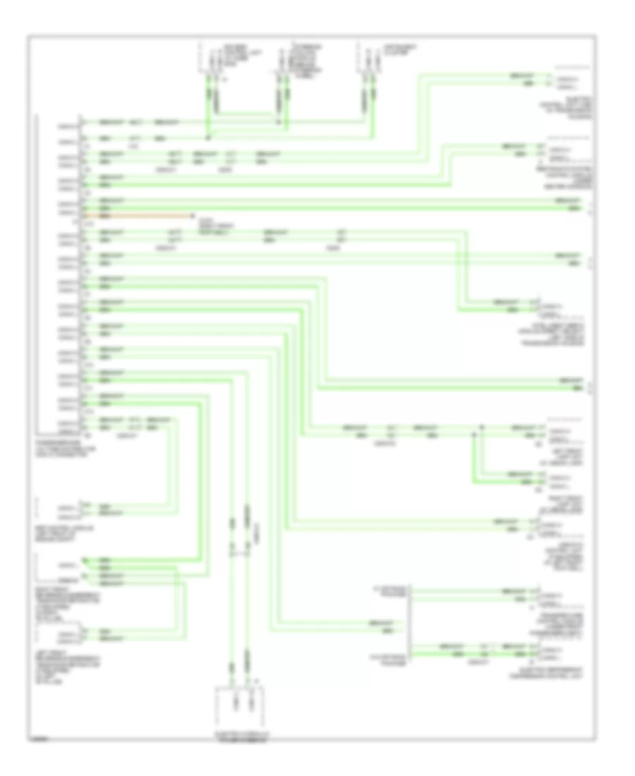
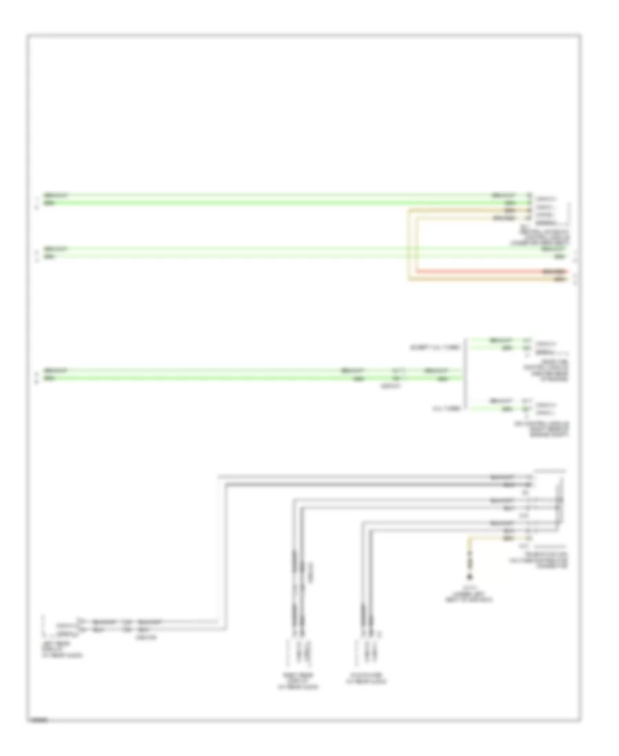
High/Low Bus Wiring Diagram (1 of 4) for Mercedes-Benz GL350 2012
 https://portal-diagnostov.com/license.html
Automotive Electricians Portal FZCO
Automotive Electricians Portal FZCO
https://portal-diagnostov.com/license.html
https://portal-diagnostov.com/license.html
Automotive Electricians Portal FZCO
Automotive Electricians Portal FZCOList of elements for High/Low Bus Wiring Diagram (1 of 4) for Mercedes-Benz GL350 2012:
- Airmatic control unit (if equipped) (in left front footwell)
- C10
- C11
- C12
- C13
- Can-c h
- Can-c l
- Eis (ezs) control unit (w/ knee bag)
- Electric control unit (vgs) (in transmission housing)
- Electric refrigerant compressor control unit
- Electro hydraulic power steering
- Esp control module (left front of engine compt)
- Instrument cluster
- Intelligent servo module (direct select) (left side of transmission housing)
- Left front lamp unit (w/ xenon lamp)
- Left front reversible emergency tensioning retractor (if equipped) (in left "b" pillar)
- Passenger-side voltage distributor (can c) connector
- Restraints system control module (under center console)
- Right front lamp unit (w/ xenon lamp)
- Right front reversible emergency tensioning retractor (if equipped) (in right "b" pillar)
- Steering column module (behind steering wheel)
- Transfer case control module (under front passenger's seat)
- W/ off road package
- W/o off road package
- W15/1 (right front footwell)
- X18
- X22/6
- X25/2-c1
- X25/2-c2
High/Low Bus Wiring Diagram (2 of 4) for Mercedes-Benz GL350 2012
 https://portal-diagnostov.com/license.html
Automotive Electricians Portal FZCO
Automotive Electricians Portal FZCO
https://portal-diagnostov.com/license.html
https://portal-diagnostov.com/license.html
Automotive Electricians Portal FZCO
Automotive Electricians Portal FZCOList of elements for High/Low Bus Wiring Diagram (2 of 4) for Mercedes-Benz GL350 2012:
- 3.0l turbo
- C10
- C13
- Can-a h
- Can-a l
- Can-b h
- Can-b l
- Can-c h
- Can-c l
- Cdi control module (right rear of engine compt)
- Central gateway control module (under driver's seat)
- Dvd player (w/ rear audio)
- Except 3.0l turbo
- Left rear display (w/ rear audio)
- Me-sfi (me) control module (center rear of engine)
- Right rear display (w/ rear audio)
- Sl1
- Telematics can voltage distributor connector
- W17/1 (under left seat of 2nd row)
- X25/2-c1
- X55/3-c6
- X55/4-c6
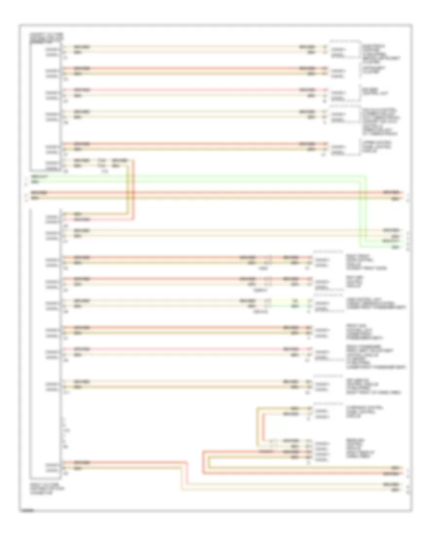
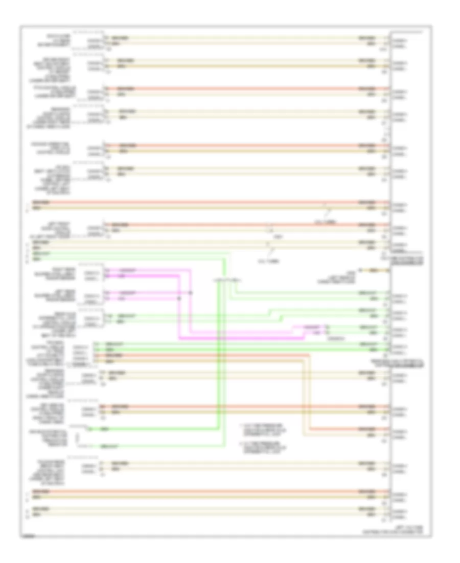
High/Low Bus Wiring Diagram (3 of 4) for Mercedes-Benz GL350 2012
 https://portal-diagnostov.com/license.html
Automotive Electricians Portal FZCO
Automotive Electricians Portal FZCO
https://portal-diagnostov.com/license.html
https://portal-diagnostov.com/license.html
Automotive Electricians Portal FZCO
Automotive Electricians Portal FZCOList of elements for High/Low Bus Wiring Diagram (3 of 4) for Mercedes-Benz GL350 2012:
- Acc (kla) control & operating unit (w/o thermotronic) comfort acc (kla) control & operating unit (w/ thermotronic)
- C10
- C11
- Can-b h
- Can-b l
- Cockpit voltage distributor (can) connector
- Eis (ezs) control unit
- Electronic compass (if equipped) (behind instrument cluster)
- Front passenger front seat adjustment control module w/ memory (if equipped) (under front passenger seat)
- Front sam control unit (under front passenger's seat)
- Instrument cluster
- Keyless go control module (if equipped) (right front of cargo area)
- Overhead control panel control module
- Rcp (hbf) control module
- Rear sam control module (right rear of cargo area)
- Right front door control module (in right front door)
- Right voltage distributor (can) connector
- Upper control panel control module
- Wss control unit (weight sensing system) (under front passenger seat)
- X18
- X18/2-c1
- X29/6-c1
- X35/2
- X55/4-c2
High/Low Bus Wiring Diagram (4 of 4) for Mercedes-Benz GL350 2012
 https://portal-diagnostov.com/license.html
Automotive Electricians Portal FZCO
Automotive Electricians Portal FZCO
https://portal-diagnostov.com/license.html
https://portal-diagnostov.com/license.html
Automotive Electricians Portal FZCO
Automotive Electricians Portal FZCOList of elements for High/Low Bus Wiring Diagram (4 of 4) for Mercedes-Benz GL350 2012:
- 3.0l turbo
- C10
- Can bus potential distributor terminating resistor
- Can-b h
- Can-b l
- Can-c h
- Can-c l
- Comand operating, display & control module
- Driver front seat adjustment control module w/ memory (if equipped) (under driver seat)
- Dvd player (w/ rear entertainment)
- Folding rear bench seat control unit (3rd rear seat) (under left seat of 2nd row)
- Hs (sih) seat ventilation & steering wheel heater control unit (under left seat of 2nd row)
- Keyless go control module (if equipped) (right front of cargo area)
- Left front door control module (in left front door)
- Left rear bumper intelligent radar sensor
- Left voltage distributor (can) connector
- Monitor & rear axle differential lock
- Pts control module (if equipped) (under driver seat)
- Rear axle differential lock control module (w/ offroad package) (under left seat of 3rd row)
- Rear end can c potential distributor connector
- Rear-end door closing control module (if equipped) (under right rear of cargo area floor)
- Rear-end door closing control module (under right rear of cargo area floor)
- Right rear bumper intelligent radar sensor
- Tpm (rdk) control module (w/ tpms) (attached to load compartment fuse & relay box)
- Voltage distributor (can) connector
- W/ tire pressure
- W/o tire pressure monitor & rear axle differential lock
- W6/6 (left rear of cargo area floor)
- X35/1
- X35/29-c4
COOLING FAN
Cooling Fan Wiring Diagram for Mercedes-Benz GL350 2012
 https://portal-diagnostov.com/license.html
Automotive Electricians Portal FZCO
Automotive Electricians Portal FZCO
https://portal-diagnostov.com/license.html
https://portal-diagnostov.com/license.html
Automotive Electricians Portal FZCO
Automotive Electricians Portal FZCOList of elements for Cooling Fan Wiring Diagram for Mercedes-Benz GL350 2012:
- (in right front wheelwell) w2/1
- (or lues)
- (top right front of engine) air pump switchover valve
- 3.0l turbo
- Aac (kla) control & operating unit (w/o thermotronic) comfort aac (kla) control & operating unit (w/ thermotronic)
- Activated charcoal filter shutoff valve (except 3.0l turbo) (in right rear wheelwell)
- Akf
- Can-b h
- Can-b l
- Can-c h
- Can-c l
- Cdi control module (3.0l turbo) me-sfi control module (except 3.0l turbo) (3.0l turbo: right rear of engine compt) (except 3.0l turbo: center rear of engine)
- Computer data lines system
- Coolant circulation pump (in left front wheelwell)
- Coolant temperature sensor (3.0l: top left side of engine) (except 3.0l: rear of left cylinder bank)
- Electric suction fan engine & ac w/ integrated control (center front of engine compt)
- Engine compartment fuse & relay box (right side of engine compt)
- Engine controls system
- Except 3.0l turbo
- Front prefuse (right rear of engine compt)
- Fuse 100a
- Fuse 15a
- Ger
- Gnd
- Heating system shutoff valve (top left rear of engine)
- Hot at all times
- Hot w/ engine circuit 87 relay energized
- Kts-s
- Mr1
- Pnk
- Red
- Refrigerant pressure sensor (in left front wheelwell)
- Sig
- Tmot
- W/ thermotronic
- W/o thermotronic
- W9 (left side of engine compt)
- X18
- X25/2-c1
- Zwp
CRUISE CONTROL
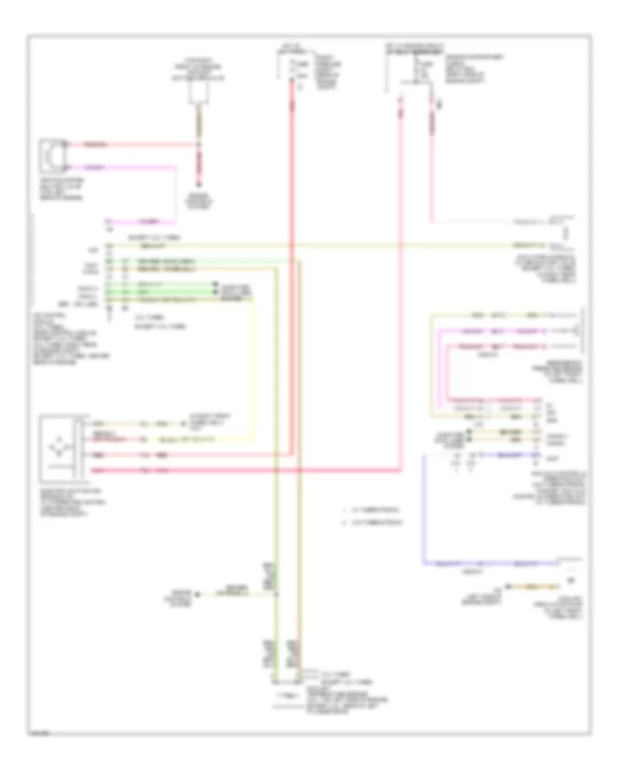
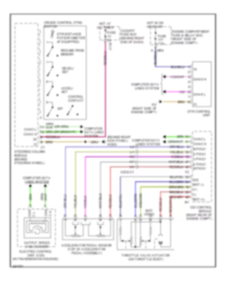
Cruise Control Wiring Diagram for Mercedes-Benz GL350 2012
 https://portal-diagnostov.com/license.html
Automotive Electricians Portal FZCO
Automotive Electricians Portal FZCO
https://portal-diagnostov.com/license.html
https://portal-diagnostov.com/license.html
Automotive Electricians Portal FZCO
Automotive Electricians Portal FZCOList of elements for Cruise Control Wiring Diagram for Mercedes-Benz GL350 2012:
- (+)
- (-)
- (behind right kick panel) w29/2
- (not used)
- Accel/ set
- Accelerator pedal sensor (top of accelerator pedal assembly)
- C h
- Can
- Can c l
- Can-c h
- Can-c l
- Can-s h
- Can-s l
- Cdi control module (right rear of engine compt)
- Cockpit fuse box (behind right end of dash)
- Computer data lines system
- Control contact
- Cruise control (tpm) switch
- Decel/ set
- Dtr control unit
- Dtr distance potentiometer (if equipped)
- E pwg1
- Electric control unit (vgs) (in transmission housing)
- Engine compartment fuse & relay box (right side of engine compt)
- Fuse 5a c13a
- Fuse 7.5a
- Hot at all times
- Hot in on or start
- M pwg1
- Mot (+)
- Mot (-)
- Mr4
- Off
- Output speed (vgs) sensor
- Resume from memory
- Sig
- Steering column module (behind steering wheel)
- Throttle valve actuator (on throttle body)
- U pwg1
- W2 (right side of engine compt)
- X25/2-c1
DEFOGGERS
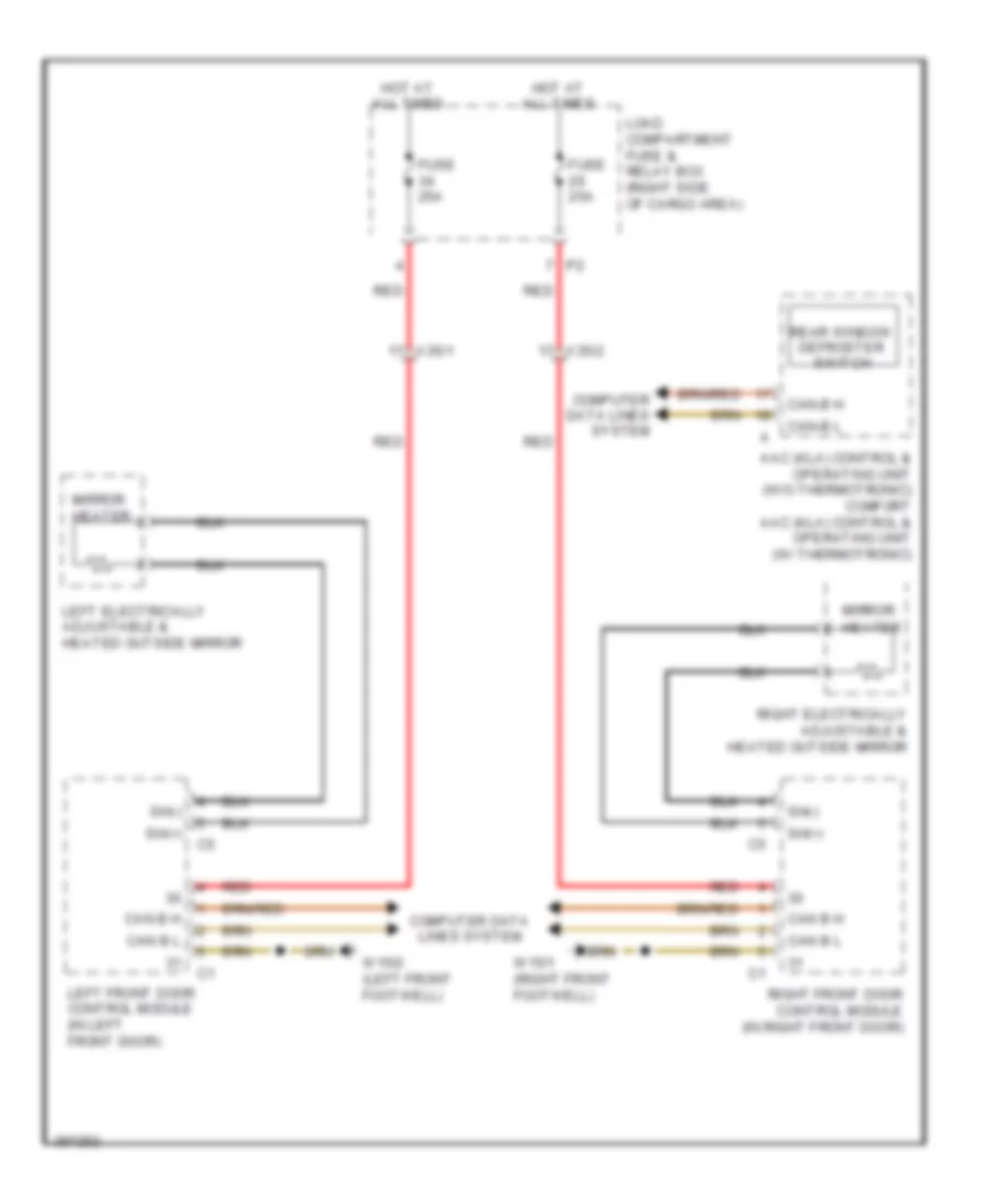
Heated Mirrors Wiring Diagram for Mercedes-Benz GL350 2012
 https://portal-diagnostov.com/license.html
Automotive Electricians Portal FZCO
Automotive Electricians Portal FZCO
https://portal-diagnostov.com/license.html
https://portal-diagnostov.com/license.html
Automotive Electricians Portal FZCO
Automotive Electricians Portal FZCOList of elements for Heated Mirrors Wiring Diagram for Mercedes-Benz GL350 2012:
- Aac (kla) control & operating unit (w/o thermotronic) comfort aac (kla) control & operating unit (w/ thermotronic)
- Can b h
- Can b l
- Can-b h
- Can-b l
- Computer data lines system
- Fuse 25a
- Hot at all times
- Left electrically adjustable & heated outside mirror
- Left front door control module (in left front door)
- Load compartment fuse & relay box (right side of cargo area)
- Mirror heater
- Rear window defroster switch
- Red
- Right electrically adjustable & heated outside mirror
- Right front door control module (in right front door)
- Sh(+)
- Sh(-)
- W15/1 (right front footwell)
- W15/2 (left front footwell)
- X35/1
- X35/2
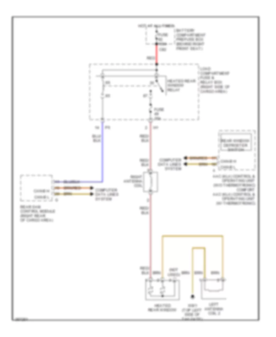
Rear Defogger Wiring Diagram for Mercedes-Benz GL350 2012
 https://portal-diagnostov.com/license.html
Automotive Electricians Portal FZCO
Automotive Electricians Portal FZCO
https://portal-diagnostov.com/license.html
https://portal-diagnostov.com/license.html
Automotive Electricians Portal FZCO
Automotive Electricians Portal FZCOList of elements for Rear Defogger Wiring Diagram for Mercedes-Benz GL350 2012:
- (not
- Aac (kla) control & operating unit (w/o thermotronic) comfort aac (kla) control & operating unit (w/ thermotronic)
- Battery compartment prefuse box (behind right front seat)
- C82
- Can-b h
- Can-b l
- Computer data lines system
- Fuse 100a
- Fuse 30a
- Heated rear window
- Heated rear window relay
- Hot at all times
- Left antenna coil 2
- Load compartment fuse & relay box (right side of cargo area)
- Rear sam control module (right rear of cargo area)
- Rear window defroster switch
- Red
- Right antenna coil
- Used)
- W8/1 (top left side of tailgate)
ELECTRONIC POWER STEERING
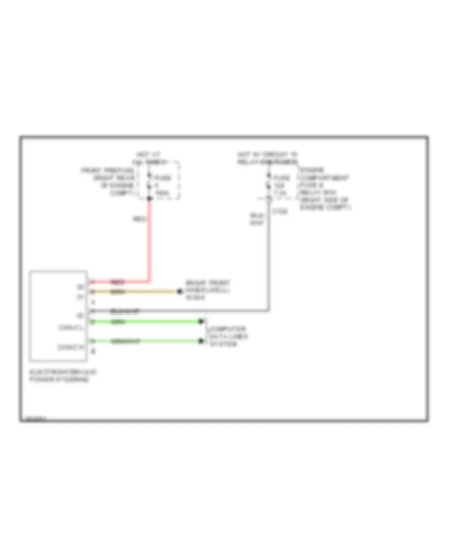
Electro Hydraulic Power Steering Wiring Diagram for Mercedes-Benz GL350 2012
 https://portal-diagnostov.com/license.html
Automotive Electricians Portal FZCO
Automotive Electricians Portal FZCO
https://portal-diagnostov.com/license.html
https://portal-diagnostov.com/license.html
Automotive Electricians Portal FZCO
Automotive Electricians Portal FZCOList of elements for Electro Hydraulic Power Steering Wiring Diagram for Mercedes-Benz GL350 2012:
- (right front wheelwell) w30/4
- C124
- Can-c h
- Can-c l
- Computer data lines system
- Electrohydraulic power steering
- Engine compartment fuse & relay box (right side of engine compt)
- Front prefuse (right rear of engine compt)
- Fuse 100a
- Fuse 7.5a
- Hot at all times
- Hot w/ circuit 15 relay energized
- Red
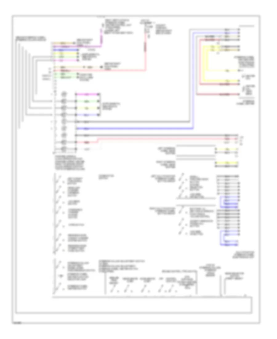
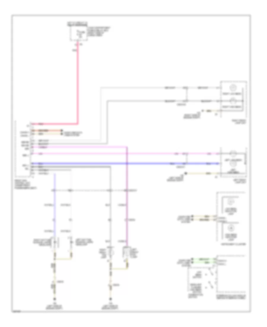
Power Steering Column Wiring Diagram for Mercedes-Benz GL350 2012
 https://portal-diagnostov.com/license.html
Automotive Electricians Portal FZCO
Automotive Electricians Portal FZCO
https://portal-diagnostov.com/license.html
https://portal-diagnostov.com/license.html
Automotive Electricians Portal FZCO
Automotive Electricians Portal FZCOList of elements for Power Steering Column Wiring Diagram for Mercedes-Benz GL350 2012:
- (behind right kick panel) w29/2
- (behind steering wheel) steering column module
- (top of steering column) steering angle sensor
- 13a
- Accelerate & set
- Accept/terminate phone call button
- Buttons + & -, setting of specific functions & volume control
- Can-c h
- Can-c l
- Cockpit fuse box (behind right end of dash)
- Combination switch
- Computer data lines system
- Control contact
- Cruise control (tpm) switch
- Decelerate & set
- Dtr distance potentiometer (if equipped)
- Fanfare horns & clock spring contact (fanfare horns: center front of engine compt) (clock spring contact: top of steering column)
- Fuse 5a
- Gear selector switch direct select
- Headlamp flasher/ highbeam switch
- Heater coil
- Heater coil temp sens
- Hot at all times
- Left & right turn signal switch
- Left multi-function steering wheel button group
- Left steering wheel gear shifter
- Lhz
- Lin
- Low beam switch
- Multi-function steering wheel electronics unit
- Off
- Rear-end door intermittent wash switch
- Rear-end door window washer system switch
- Red
- Resume from memory
- Right multi-function steering wheel button group
- Right steering wheel gear shifter
- Scroll forward/ back button
- Seat ventilation & steering wheel heater control unit (if equipped) (under left c2 seat of 2nd seat row)
- Steering column adjustment raise/lower, forward/back switch
- Steering column adjustment switch (w/ esc) steering column adjustment/ steering wheel heater switch (if equipped)
- Steering wheel heater
- Steering wheel heater function indicator lamp
- Steering wheel heater switch
- Steering wheel heater/horn electronics (if equipped)
- System selection button
- Vcs (sbs) off button
- Vcs (sbs) on button
- Windshield washer system switch
- Wipe switch
- X18-c2
ELECTRONIC SUSPENSION
Electronic Suspension Wiring Diagram (1 of 2) for Mercedes-Benz GL350 2012
 https://portal-diagnostov.com/license.html
Automotive Electricians Portal FZCO
Automotive Electricians Portal FZCO
https://portal-diagnostov.com/license.html
https://portal-diagnostov.com/license.html
Automotive Electricians Portal FZCO
Automotive Electricians Portal FZCOList of elements for Electronic Suspension Wiring Diagram (1 of 2) for Mercedes-Benz GL350 2012:
- (-)
- (top of left front shock tower) (w/ ads) left front body lateral acceleration sensor
- (top of right front shock tower) (w/ ads) right front body lateral acceleration sensor
- 87a
- Ablv
- Air suspension compressor relay
- Airmatic compressor unit (behind right side of front bumper)
- Airmatic control unit (in left front footwell)
- Circuit 31 left footwell voltage distributor connector 1
- Dv1
- Dv2
- Dvv
- Engine compartment fuse & relay box (right side of engine compt)
- Fuse 15a
- Fuse 40a
- Fuse 5a
- Hot at all times
- Hot in on or start
- Left front axle damping valve unit (w/ ads) (on left front axle)
- Left front level sensor (on left front frame rails)
- Load compartment fuse & relay box (right side of of cargo area)
- Mr1
- Mr2
- Nca
- Pnk
- Red
- Rel
- Right front axle damping valve unit (w/ ads) (on right front axle)
- Right front level sensor (on right front frame rails)
- Sig
- W15/2 (left front footwell)
- W2 (right side of engine compt)
- X25/2-c1
- X25/2-c2
- Zlv
Electronic Suspension Wiring Diagram (2 of 2) for Mercedes-Benz GL350 2012
 https://portal-diagnostov.com/license.html
Automotive Electricians Portal FZCO
Automotive Electricians Portal FZCO
https://portal-diagnostov.com/license.html
https://portal-diagnostov.com/license.html
Automotive Electricians Portal FZCO
Automotive Electricians Portal FZCOList of elements for Electronic Suspension Wiring Diagram (2 of 2) for Mercedes-Benz GL350 2012:
- (-)
- (not used)
- Airmatic control unit (in left front footwell)
- Airmatic valve unit (behind right end of front bumper)
- Can-c h
- Can-c l
- Central reservoir charge valve
- Computer data lines system
- Dv1
- Dv2
- Dvv
- Front prefuse (right rear of engine compt)
- Front sam control unit (under front passenger's seat)
- Fuse 100a
- Hot at all times
- Left front level control valve
- Left rear axle damping valve unit (w/ ads) (at left rear wheel assembly)
- Left rear level control valve
- Left rear level sensor (on left rear frame rail)
- Nca
- Pnk
- Pnk/red
- Pressure sensor
- Red
- Right front level control valve
- Right rear axle damping valve unit (w/ ads) (at right rear wheel assembly)
- Right rear level sensor (on right rear frame rail)
- Right rear level valve
- Sig
- X25/2-c2
ENGINE PERFORMANCE
3.0L TURBO DIESEL
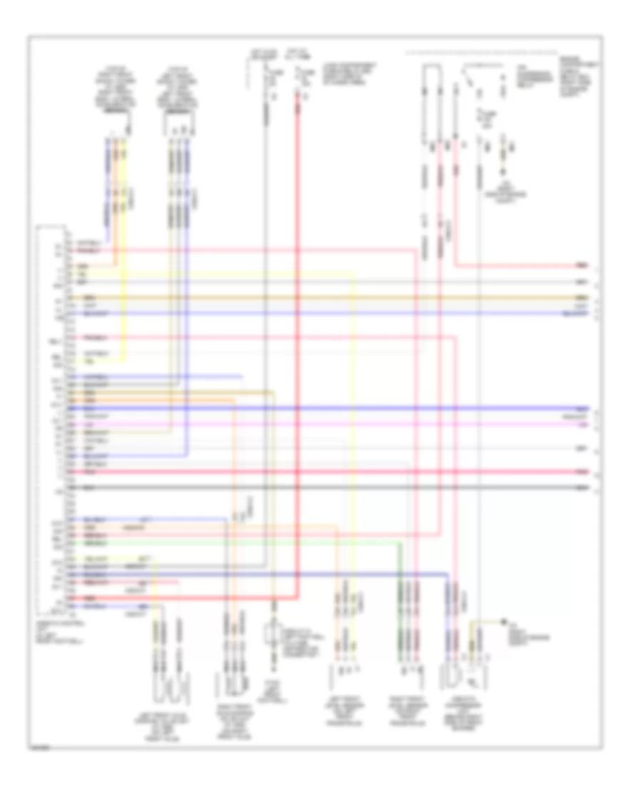
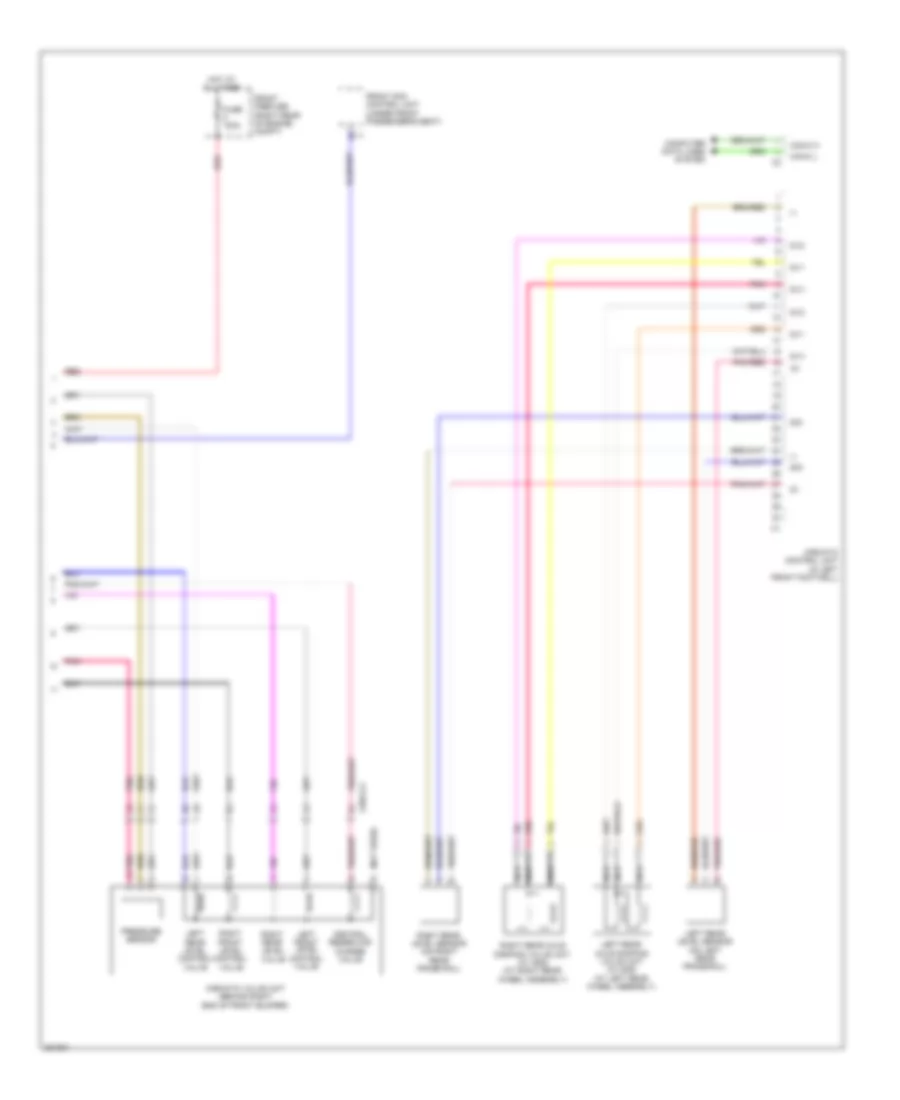
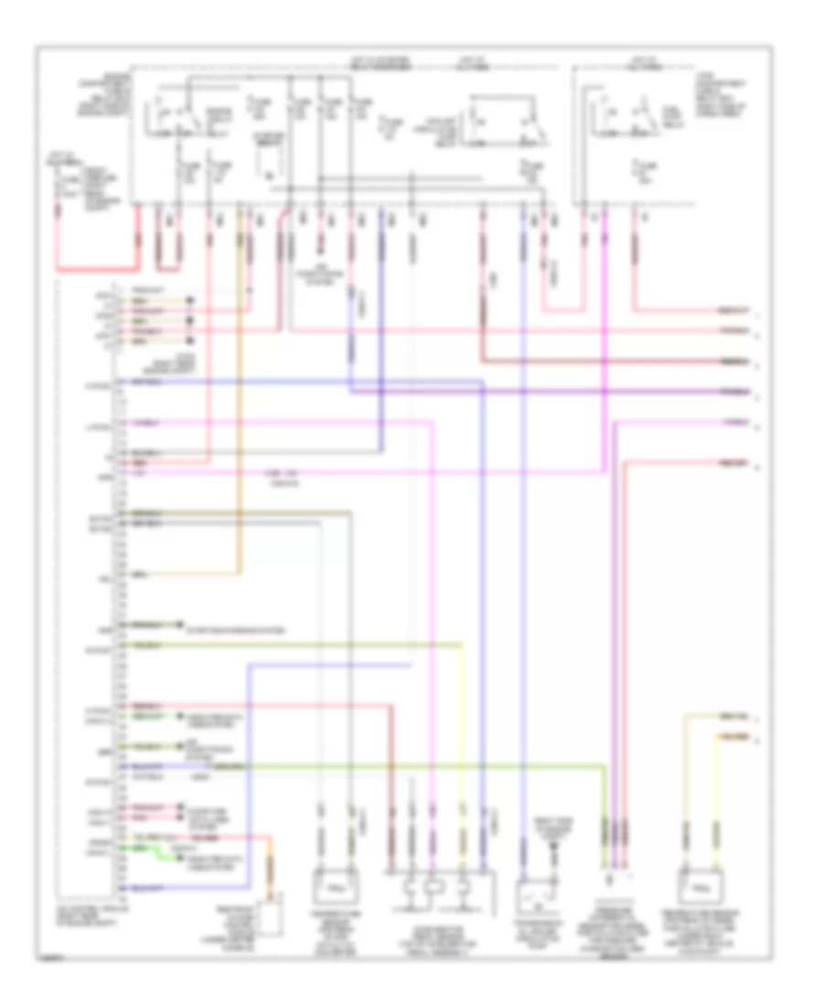
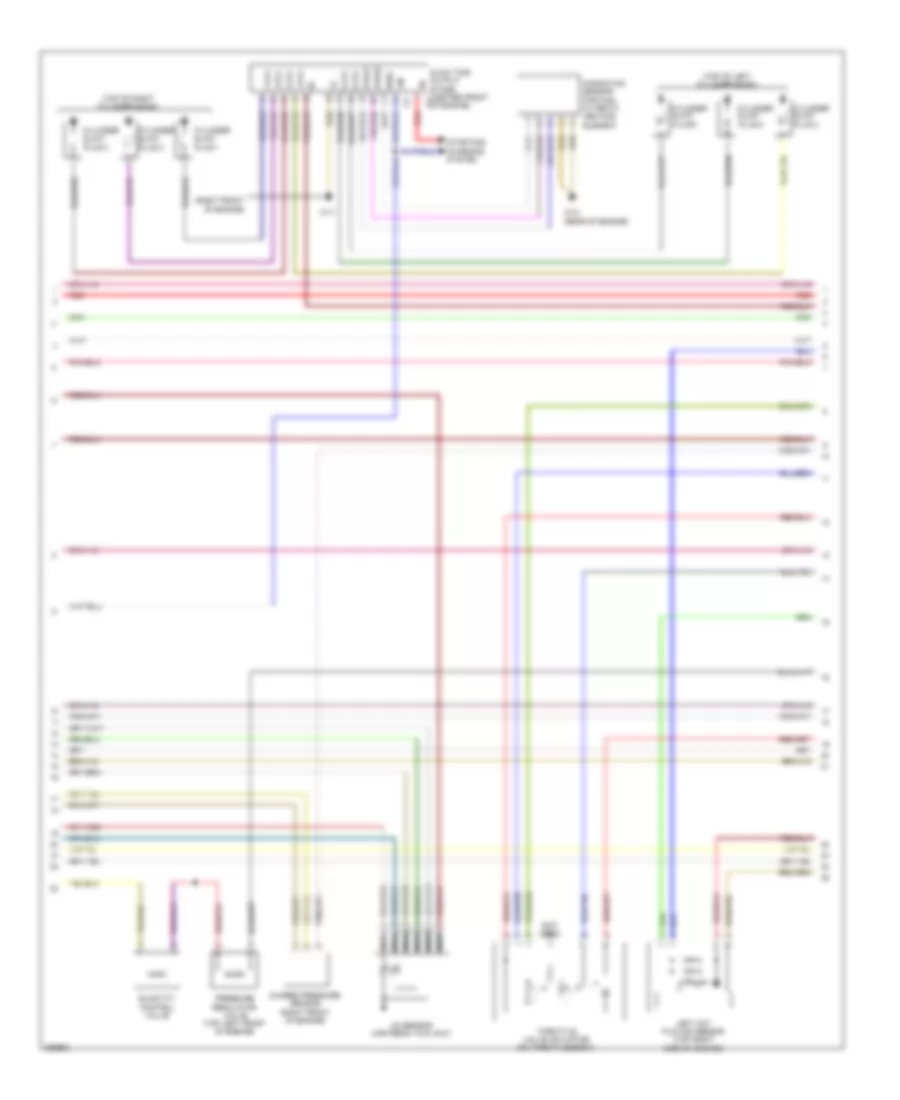
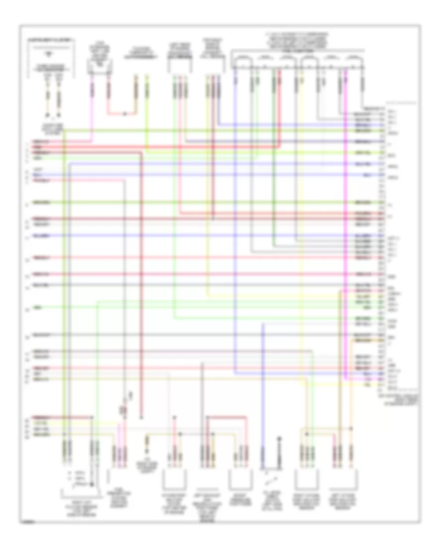
3.0L Turbo Diesel, Engine Performance Wiring Diagram (1 of 6) for Mercedes-Benz GL350 2012
 https://portal-diagnostov.com/license.html
Automotive Electricians Portal FZCO
Automotive Electricians Portal FZCO
https://portal-diagnostov.com/license.html
https://portal-diagnostov.com/license.html
Automotive Electricians Portal FZCO
Automotive Electricians Portal FZCOList of elements for 3.0L Turbo Diesel, Engine Performance Wiring Diagram (1 of 6) for Mercedes-Benz GL350 2012:
- (right side of engine compt) w2
- 87d1
- 87d2
- Accelerator pedal sensor (top of accelerator pedal assembly)
- Air conditioning system
- Anr
- Can-c h
- Can-c l
- Can-i-h
- Can-i-l
- Cdi control module (right rear of engine compt)
- Computer data lines system
- Coolant circulation pump relay
- Crash
- E pwg1
- Engine circuit relay
- Engine compartment fuse & relay box (right side of engine compt)
- Exts3
- Exts4
- Front prefuse (right rear of engine compt)
- Fuel pump relay
- Fuse 100a
- Fuse 10a
- Fuse 15a
- Fuse 20a
- Fuse 25a
- Fuse 5a
- Ger
- Hot at all times
- Hot w/ starter relay energized
- Hrl
- Kpr
- Load compartment fuse & relay box (right side of cargo area)
- M pwg1
- Mr1
- Mr2
- Mr3
- Mr4
- Pnk
- Pressure differential sensor for diesel particulate filter for onboard diagnostics (obd) sensor
- Red
- Restraint system control module (under center console)
- Sig
- Starter relay
- Starting/charging system
- Temperature sensor upstream of diesel particulate filter (under right center of vehicle, in exhaust)
- Temperature sensor upstream of scr catalytic converter
- Transmission oil cooler circulation pump
- U pwg1
- W16/4 (right rear engine compt)
- X18/7
- X22/6
- X25/2-c1
- X25/2-c2
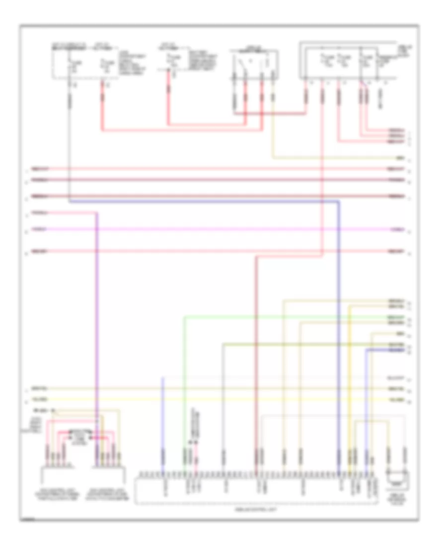
3.0L Turbo Diesel, Engine Performance Wiring Diagram (2 of 6) for Mercedes-Benz GL350 2012
 https://portal-diagnostov.com/license.html
Automotive Electricians Portal FZCO
Automotive Electricians Portal FZCO
https://portal-diagnostov.com/license.html
https://portal-diagnostov.com/license.html
Automotive Electricians Portal FZCO
Automotive Electricians Portal FZCOList of elements for 3.0L Turbo Diesel, Engine Performance Wiring Diagram (2 of 6) for Mercedes-Benz GL350 2012:
- (not used)
- Battery compartment prefuse box (behind right front seat)
- C81
- Can-i h
- Can-i l
- Computer data lines system
- Fuse 15a
- Fuse 20a
- Fuse 40a
- Fuse 5a
- Fuse 7.5a
- Gr pras
- Hot at all times
- Hot w/ circuit 15 relay energized
- Ia pras
- Ia trats
- Is t15
- Lines system computer data
- Load compartment fuse & relay box (right side of cargo area)
- Nox control unit downstream of diesel particulate filter
- Nox control unit downstream of scr catalytic converter
- Os rarv
- Ot rapmp
- Ov rh1
- Pnk
- Ramvh1
- Ramvl1
- Red
- Reserve fuse
- Vv bat
- W15/1 (right front footwell)
3.0L Turbo Diesel, Engine Performance Wiring Diagram (3 of 6) for Mercedes-Benz GL350 2012
 https://portal-diagnostov.com/license.html
Automotive Electricians Portal FZCO
Automotive Electricians Portal FZCO
https://portal-diagnostov.com/license.html
https://portal-diagnostov.com/license.html
Automotive Electricians Portal FZCO
Automotive Electricians Portal FZCOList of elements for 3.0L Turbo Diesel, Engine Performance Wiring Diagram (3 of 6) for Mercedes-Benz GL350 2012:
- (left rear of
- Bf rals1
- Bf rals2
- Bf rals3
- Cargo area floor)
- Delivery pump
- Empty
- Fill level sensor
- Full
- Gg bat 2
- Heating element
- Nca
- Os mrly
- Os raht1
- Os raht2
- Os raht3
- Pressure line heating element
- Pressure sensor
- Red
- Reserve
- Reversing valve
- Tank heating element & temperature sensor
- Used) (not
- Vv 5vpras
- Vv bat
- W6/6
- W6/6 (left rear of cargo area floor)
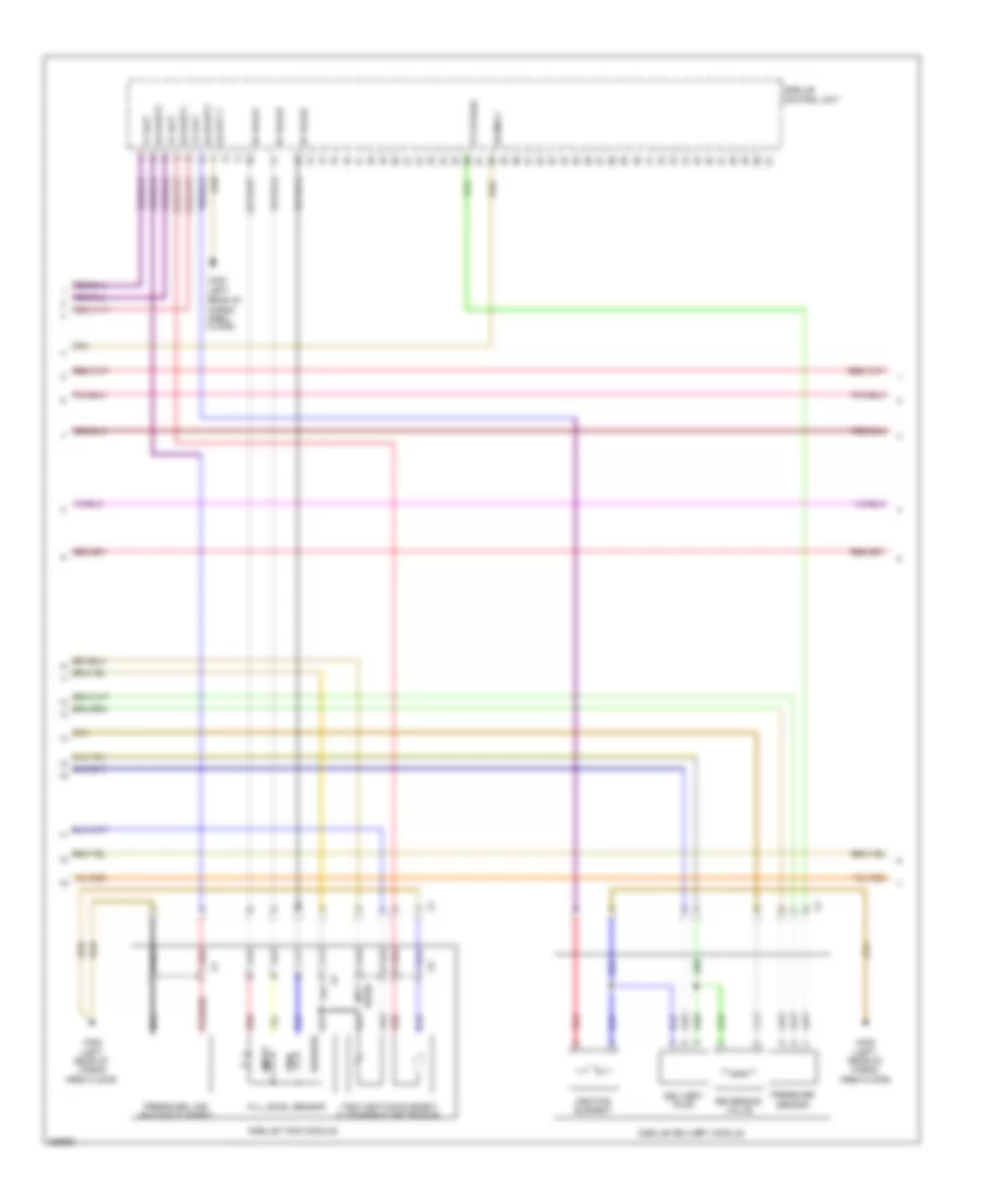
3.0L Turbo Diesel, Engine Performance Wiring Diagram (4 of 6) for Mercedes-Benz GL350 2012
 https://portal-diagnostov.com/license.html
Automotive Electricians Portal FZCO
Automotive Electricians Portal FZCO
https://portal-diagnostov.com/license.html
https://portal-diagnostov.com/license.html
Automotive Electricians Portal FZCO
Automotive Electricians Portal FZCOList of elements for 3.0L Turbo Diesel, Engine Performance Wiring Diagram (4 of 6) for Mercedes-Benz GL350 2012:
- (+)
- (-)
- (at differential) differential pressure sensor (dpf)
- (bottom left side of oil pan) oil temperature sensor
- (center rear of engine) exhaust back pressure sensor
- (in right side of fuel tank) right fuel pump
- (left front of engine) fuel temperature sensor
- (right front of engine) charge air temperature sensor
- (top left side of engine) coolant temperature sensor
- (top left side of engine) downstream of air filter pressure sensor
- A-eka-r
- Cdi control module (right rear of engine compt)
- Cvh
- Drs
- Eka-a
- Exhaust gas recirculation temperature sensor
- Exts1
- Flwtr
- Iats3
- Inj h
- Kts-s
- Ldf-1
- Ldr
- Ls1
- Ls1hk
- Ls1p
- Lsh1hk
- Lshk
- Nca
- Rail pressure sensor (top right rear of engine)
- Rds
- Red
- Sig
- T2-s
- Tag1
- Temperature sensor upstream of turbocharger
- Tmot
- Toel
- Upstream twc (kat) temperature sensor
- W17 (under right seat of 2nd row)
- X18/3-c1
- Zme+
3.0L Turbo Diesel, Engine Performance Wiring Diagram (5 of 6) for Mercedes-Benz GL350 2012
 https://portal-diagnostov.com/license.html
Automotive Electricians Portal FZCO
Automotive Electricians Portal FZCO
https://portal-diagnostov.com/license.html
https://portal-diagnostov.com/license.html
Automotive Electricians Portal FZCO
Automotive Electricians Portal FZCOList of elements for 3.0L Turbo Diesel, Engine Performance Wiring Diagram (5 of 6) for Mercedes-Benz GL350 2012:
- (not used)
- (right front of engine)
- (top of left cylinder bank)
- (top of right cylinder bank)
- 1.zyl
- 2.zyl
- 3.zyl
- 4.zyl
- 5.zyl
- 6.zyl
- Charge pressure sensor (right front of engine)
- Consation sensor for fuel filter w/ heating element
- Cylinder glow plug 1
- Cylinder glow plug 2
- Cylinder glow plug 3
- Cylinder glow plug 4
- Cylinder glow plug 5
- Cylinder glow plug 6
- Glow time output stage (center front c1 of engine)
- Kfh21
- Kfhzz
- Left hot film maf sensor (top right side of engine)
- Lin
- Nca
- O2 sensor upstream twc (kat)
- Pressure regulator valve (top left front of engine)
- Quantity control valve
- Red
- Starting/ charging system
- Throttle valve actuator (on throttle body)
- W11
- W12 (rear of engine)
- Wss
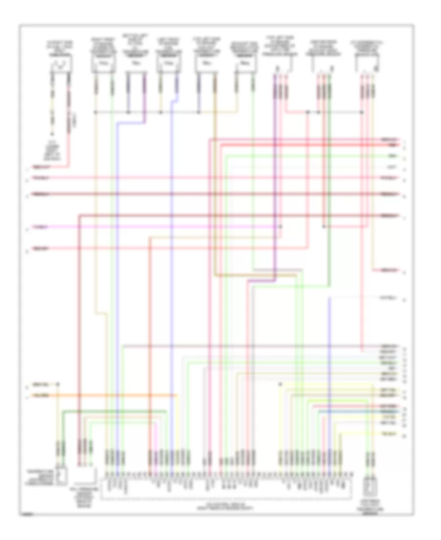
3.0L Turbo Diesel, Engine Performance Wiring Diagram (6 of 6) for Mercedes-Benz GL350 2012
 https://portal-diagnostov.com/license.html
Automotive Electricians Portal FZCO
Automotive Electricians Portal FZCO
https://portal-diagnostov.com/license.html
https://portal-diagnostov.com/license.html
Automotive Electricians Portal FZCO
Automotive Electricians Portal FZCOList of elements for 3.0L Turbo Diesel, Engine Performance Wiring Diagram (6 of 6) for Mercedes-Benz GL350 2012:
- "check engine" mil indicator
- (+)
- (-)
- (1, 2 & 3: on right cylinder bank, above respective cylinder) (4, 5 & 6: on left cylinder bank, above respective cylinder) fuel injectors
- (left rear of engine) crankshaft hall sensor
- (top of engine) vent line heater element
- (top right side of engine) camshaft hall sensor
- A-eka-i
- Agr
- Boost pressure positioner
- Can- b h
- Can- b l
- Cdi control module (right rear of engine compt)
- Computer data lines system
- Dds
- Drs
- Drv
- Etc
- Fuel preheating system heating element
- Hfm-0
- Hfm-1
- Hfm-2
- Inj h
- Inj l
- Instrument cluster
- Intake port shutoff motor (top center of engine)
- Kwg
- Left exhaust gas recirculation positioner (top left rear of engine)
- Left intake port shutoff end position sensor
- Mot (+)
- Mot (-)
- Nca
- Ods
- Oil level check switch (left side of oil pan)
- Red
- Right hot film maf sensor (top left side of engine)
- Right intake port shutoff end position sensor
- Sig
- Two-disk thermostat heating element
- W2 (right side of engine compt)
- X18/7
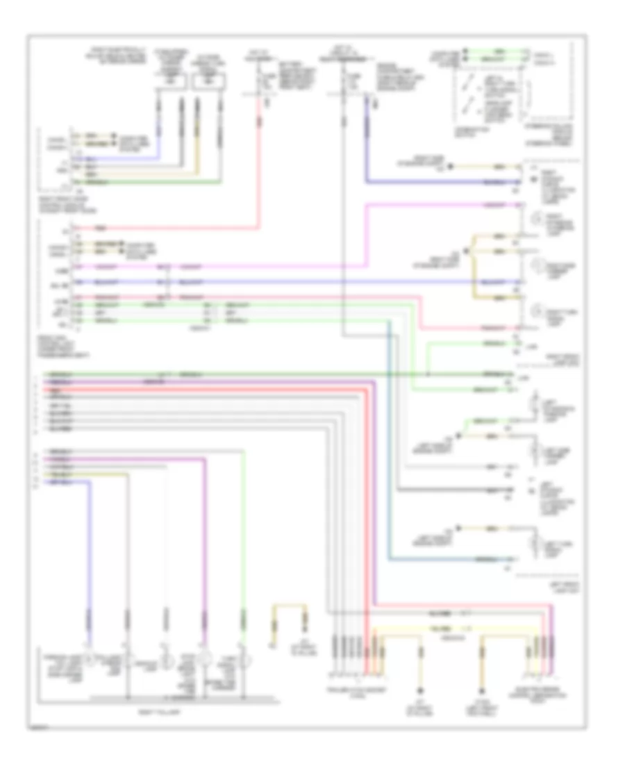
EXTERIOR LIGHTS
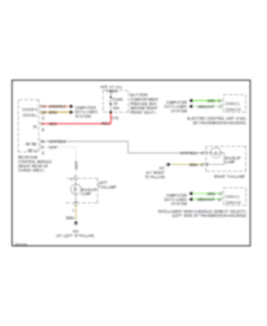
Backup Lamps Wiring Diagram for Mercedes-Benz GL350 2012
 https://portal-diagnostov.com/license.html
Automotive Electricians Portal FZCO
Automotive Electricians Portal FZCO
https://portal-diagnostov.com/license.html
https://portal-diagnostov.com/license.html
Automotive Electricians Portal FZCO
Automotive Electricians Portal FZCOList of elements for Backup Lamps Wiring Diagram for Mercedes-Benz GL350 2012:
- Backup lamp
- Battery compartment prefuse box (behind right front seat)
- C79
- Can b h
- Can b l
- Can-c h
- Can-c l
- Computer data lines system
- Electric control unit (vgs) (in transmission housing)
- Fuse 60a
- Hot at all times
- Intelligent servo module (direct select) (left side of transmission housing)
- Left taillamp
- Rear sam control module (right rear of cargo area)
- Red
- Rf li
- Rf re
- Right taillamp
- W6 (at left "d" pillar)
- W7 (at right "d" pillar)
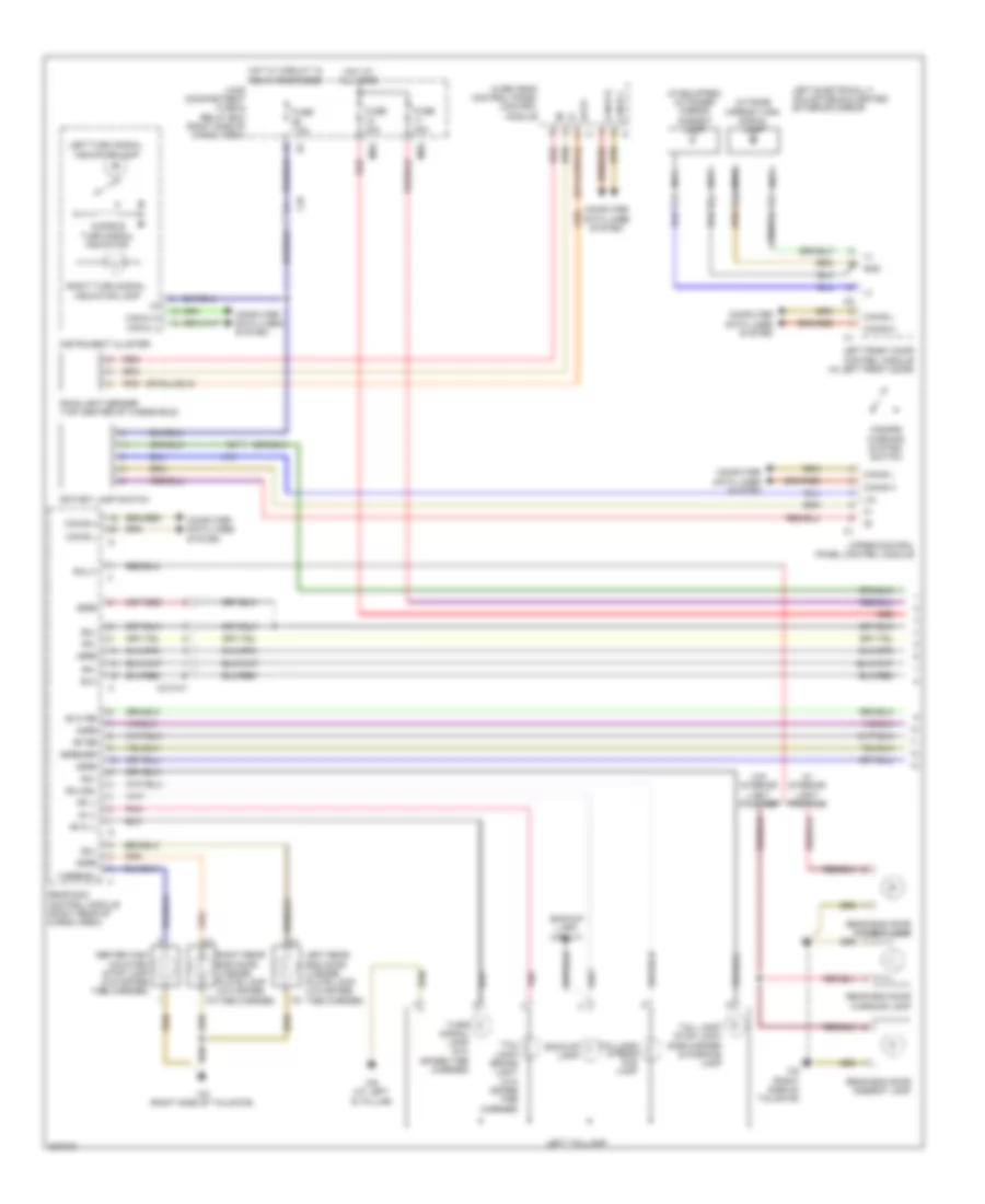
Exterior Lamps Wiring Diagram (1 of 2) for Mercedes-Benz GL350 2012
 https://portal-diagnostov.com/license.html
Automotive Electricians Portal FZCO
Automotive Electricians Portal FZCO
https://portal-diagnostov.com/license.html
https://portal-diagnostov.com/license.html
Automotive Electricians Portal FZCO
Automotive Electricians Portal FZCOList of elements for Exterior Lamps Wiring Diagram (1 of 2) for Mercedes-Benz GL350 2012:
- (+)
- (if equipped) outsider mirror ambient lamp
- 3 bremsl
- 49 hi li
- 49 hi re
- 49li
- 49re
- 54 li
- 54re
- 58li
- 58li/55l
- 58re
- 58re/55r
- Audible turn signal indicator
- Backup lamp
- Backup lamp circuit
- Bla
- Can-b h
- Can-b l
- Can-c h
- Can-c l
- Center high mounted stop lamp (w/o spare tire carrier)
- Computer data lines system
- Data
- Fuse 20a
- Fuse 30a
- Fuse 7.5a
- Gnd
- Hazard warning system switch
- Hot at all times
- Hot w/ circuit 15 relay energized
- Indicator lamp
- Instrument cluster
- Left electrically adjustable & heated exterior mirror
- Left front door control module (in left front door)
- Left rear end door license plate lamp (w/o spare tire carrier)
- Left taillamp
- Left turn signal
- Lin
- Load compartment fuse & relay box (right side of cargo area)
- Module
- Ms5
- Ms6
- Nca
- Outside mirror turn signal lamp
- Over head control panel control
- Pnk
- Rain/light sensor (top center of windshield)
- Rear end door ambient lamp
- Rear end door warning lamp
- Rear sam control module (right rear of cargo area)
- Red
- Rf li
- Rf re
- Rfl
- Right rear end door license plate lamp (w/o spare tire carrier)
- Right turn signal
- Rotary lamp switch
- Rwlt
- Tail lamp/ brake light (w/o spare tire carrier)
- Tail lamp/ stop lamp/ side marker & parking lamp
- Taillamp & rear fog lamp
- Turn signal lamp (w/o spare tire carrier)
- Upper control panel control module
- W/ interior light package
- W/0 interior light package
- W6 (at left "d" pillar)
- W8 (right side of tailgate)
- X18
- X213-c1
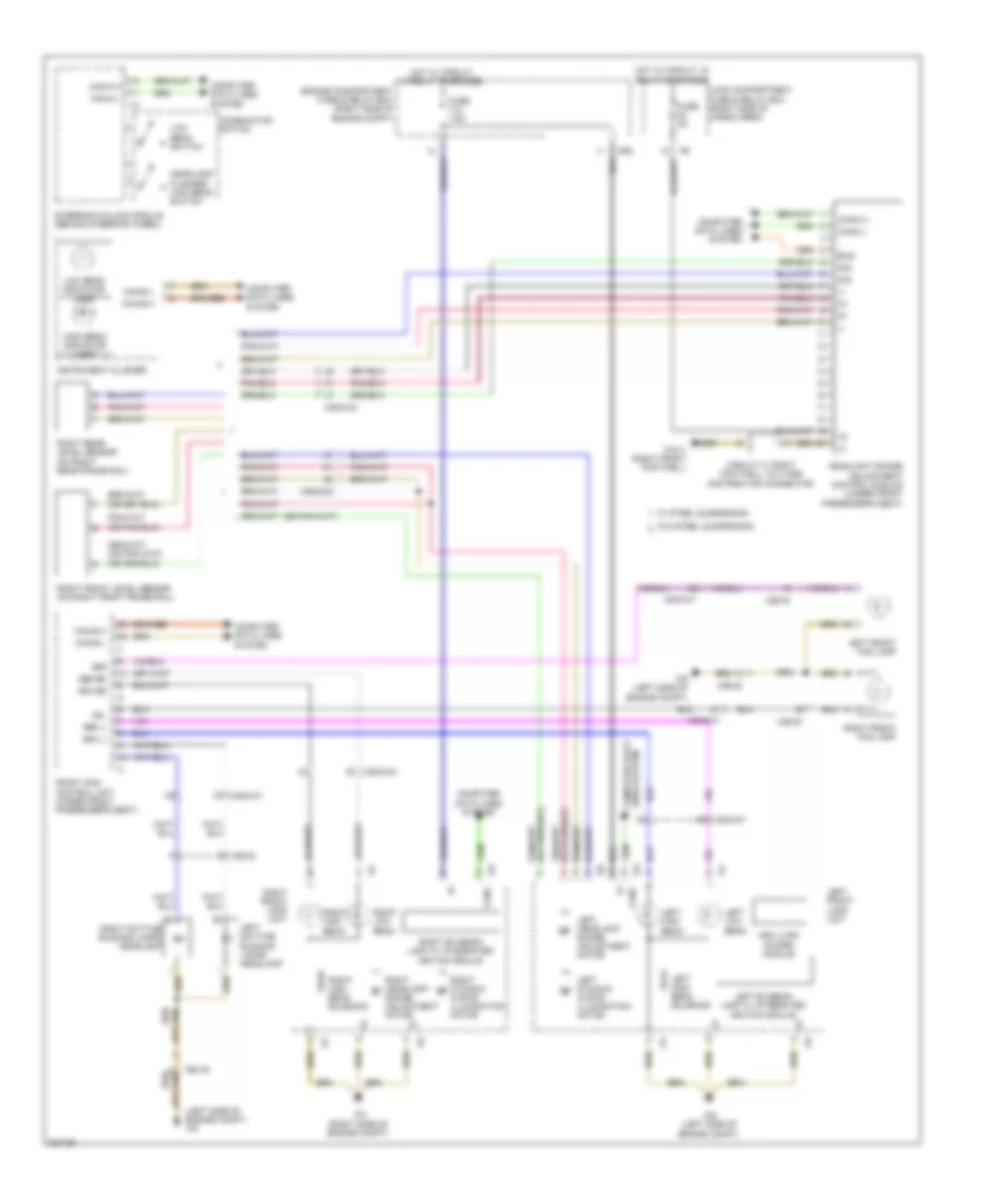
Exterior Lamps Wiring Diagram (2 of 2) for Mercedes-Benz GL350 2012
 https://portal-diagnostov.com/license.html
Automotive Electricians Portal FZCO
Automotive Electricians Portal FZCO
https://portal-diagnostov.com/license.html
https://portal-diagnostov.com/license.html
Automotive Electricians Portal FZCO
Automotive Electricians Portal FZCOList of elements for Exterior Lamps Wiring Diagram (2 of 2) for Mercedes-Benz GL350 2012:
- (+)
- (if equipped) outsider mirror ambient lamp
- (right side of engine compt) w2
- 49 re
- 49li
- 58 li sml li
- 58re
- Backup lamp
- Battery compartment prefuse box (behind right front seat)
- C88
- Can-b h
- Can-b l
- Can-c h
- Can-c l
- Combination switch
- Computer data lines system
- Electric brake control separation point
- Engine compartment fuse & relay box (right rear of engine compt)
- Front sam control unit (under front passenger's seat)
- Fuse 7.5a
- Fuse 70a
- Gnd
- Headlamp flasher/ high beam switch
- Hot at all times
- Hot w/ circuit 15 relay energized
- Left & right turn turn signal switch
- Left dynamic curve illumination (w/ xenon lamps)
- Left front lamp unit
- Left side marker lamp
- Left standing & parking lamp
- Left turn signal lamp
- Lwr
- Mr3
- Nca
- Outside mirror turn signal lamp
- Parking lamp/ tail lamp/ stop lamp & side marker lamp
- Red
- Right dynamic curve illumination (w/ xenon lamps)
- Right electrically adjustable & heated exterior mirror
- Right front door control module (in right front door)
- Right front lamp unit
- Right side marker lamp
- Right standing & parking lamp
- Right taillamp
- Right turn signal lamp
- Sml re
- Steering column module (behind steering wheel)
- Stop lamp/ brake light (w/o spare tire carrier)
- Taillamp & rear fog lamp
- Trailer hitch socket (7-pin)
- Turn signal lamp (w/o spare tire carrier)
- W15/2 (left front footwell)
- W2 (right side of engine compt)
- W7 (at right "d" pillar)
- W9 (left side of engine compt)
- X25/2-c1
- X25/2-c2
- X58/33-c2
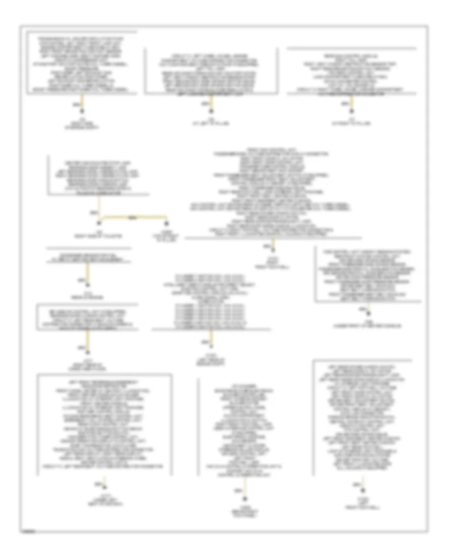
GROUND DISTRIBUTION
Ground Distribution Wiring Diagram (1 of 2) for Mercedes-Benz GL350 2012
 https://portal-diagnostov.com/license.html
Automotive Electricians Portal FZCO
Automotive Electricians Portal FZCO
https://portal-diagnostov.com/license.html
https://portal-diagnostov.com/license.html
Automotive Electricians Portal FZCO
Automotive Electricians Portal FZCOList of elements for Ground Distribution Wiring Diagram (1 of 2) for Mercedes-Benz GL350 2012:
- Cd changer, booster blower electronic blower controller, front interior socket, blower motor, upper control panel control unit, glove compartment illumination w/ switch, right front footwell lamp, media interface control unit (if equipped), electronic compass, sun sensor, instrument cluster, steering column module, eis (ezs) control unit, left front footwell lamp, aac (kla) control & operating unit & comfort aac (kla) control & operating unit
- Center high-mounted stop lamp, rear-end door ambient lamp, left rear-end door license plate lamp, right rear-end door license plate lamp, rear-end door handle switch, rear-end door warning lamp (w/o automatic rear-end door) & tailgate wiper motor
- Circuit 31 left wheel house luggage compartment voltage distributor connector, multicontour seat pneumatic pump (if equipped), left tail lamp, rear air conditioning coolant shutoff motor, left vent window obstruction sensor strip, right second row side air bag ignition squib, left second row side air bag ignition squib, rear air conditioning blower regulator & left luggage compartment lamp
- Condenser sensor for fuel filter w/ heating heating element
- Cylinder 7 ignition coil (4.6l & 5.5l), cylinder 8 ignition coil (4.6l & 5.5l), intelligent servo module for direct select, electric control unit (vgs), me-sfi (me) control module (4.6l & 5.5l), alarm signal horn, wiper motor, cylinder 1 ignition coil (4.6l & 5.5l), cylinder 2 ignition coil (4.6l & 5.5l), cylinder 3 ignition coil (4.6l & 5.5l), cylinder 4 ignition coil (4.6l & 5.5l), cylinder 5 ignition coil (4.6l & 5.5l) & cylinder 6 ignition coil (4.6l & 5.5l)
- Front sam control unit, passenger-side voltage distributor (can c) connector, right front door cl (zv) motor, right front door control unit, transfer case control module, right second seat row socket, front passenger seat adjustment switch (if equipped), front passenger front seat adjustment control module w/ memory (if equipped), front passenger side bag squib, right rear footwell lamp (interior light package), right front seat heated cushion, right front backrest heated cushion, nox control unit downstream of diesel perticular filter (3.0l turbo diesel), nox control unit downstream of scr catalytic converter (3.0l turbo diesel), right rear power window switch, right rear door cl motor, right rear door entrance & exit lamp, right rear door inside handle illumination, circuit 31 right footwell voltage distributor connector & right front illuminated door sill molding (if equipped)
- Keyless go control unit (if equipped), rear-end door closing control unit, circuit 31 left rear seat voltage distributor connector w/ backup camera & backup camera (if equipped)
- Left front reversible emergency tensioning retractor, front cigar lighter (w/ ashtray illumination), front center console cup holder illumination (w/ interior light package), front center console illumination (w/ interior light package), rcp (hbf) control module, folding rear bench seat control unit, emergency call system control unit, rear audio control unit, mb-info & telediagnosis button group, sos push button switch, high-defnition tuner control unit, comand operating display & control unit, e-net compensator, dvd player, telematics can voltage distributor connector, left rear display, right rear display, hs[sih], seat ventilation & steering wheel heater control unit & circuit 31 left rear seat voltage distributor connector
- Left rear power window switch, left rear door cl (zv) motor, left rear door entrance & exit lamp, left rear inside door handle illumination (w/ interior light package) circuit 31 left footwell voltage left front door control unit, left front door cl (zv) motor, driver seat adjustment switch, driver front seat adjustment control module (w/ memory), data link connector, parking brake indicator switch, central gateway control unit, airmatic control unit, pts control unit, driver side air bag squib, left front backseat heated cushion, left front seat heated cushion, left rear footwell lamp (w/ interior light package) & amplifier for sound system driver train can voltage left front illuminated door sill molding (if equipped)
- Rear sam control module, right tail lamp, right vent window obstruction sensor trip, right rear brake pad contact sensor, tpm (rdk) control unit, load compartment fuse & relay box, dc/ac converter control unit (w/ 115v socket) & circuit 31 right wheel house luggage compartment voltage distributor connector
- Transmission oil cooler circulation pump, dtr control unit, right front lamp unit, engine compartment fuse & relay box, right front brake pad contact sensor, left fanfare horn, right fanfare horn, airmatic compressor unit, intake port shutoff motor (3.0l turbo diesel), boost pressure positioner, left exhaust gas recirculation positioner, left exhaust gas recirculation positioner (3.0l turbo diesel) & boost pressure positioner (3.0l turbo diesel)
- W12 (rear of engine)
- W15/1 (right front footwell)
- W15/2 (left front footwell)
- W16/3 (left rear of engine compt)
- W17/1 (under left seat of 2nd row)
- W2 (right side of engine compt)
- W26 (under front of center console)
- W29/2 (behind right kick panel)
- W29/9 (top of right "d" pillar)
- W6 (at left "d" pillar)
- W7 (at right "d" pillar)
- W7/7 (right rear of cargo area floor)
- W8 (right side of tailgate)
- Wss control unit (weight sensing system), restraint system control unit, driver side air bag sensor, front passenger side air bag sensor, passenger-side frontal acceleration sensor, driver-side frontal acceleration sensor, driver door pressure sensor, front passenger door pressure sensor, driver seat belt buckle & seat belt warning switch, front passenger seat belt buckle & seat belt warning switch
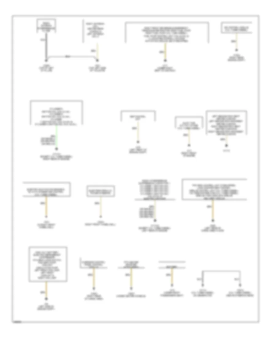
Ground Distribution Wiring Diagram (2 of 2) for Mercedes-Benz GL350 2012
 https://portal-diagnostov.com/license.html
Automotive Electricians Portal FZCO
Automotive Electricians Portal FZCO
https://portal-diagnostov.com/license.html
https://portal-diagnostov.com/license.html
Automotive Electricians Portal FZCO
Automotive Electricians Portal FZCOList of elements for Ground Distribution Wiring Diagram (2 of 2) for Mercedes-Benz GL350 2012:
- Battery
- Cdi control module (3.0l turbo diesel)
- Cylinder 5 ignition coil (5.5l & 4.6l) cylinder 6 ignition coil (5.5l & 4.6l), cylinder 7 ignition coil (5.5l & 4.6l) & cylinder 8 ignition coil (5.5l & 4.6l)
- Electric suction fan engine & ac with integrated control (3.0l turbo diesel)
- Electrohydraulic power steering
- Esp control unit
- Fuel pump control unit (4.6l & 5.5l) & illuminated door sill molding actuation module led (if equipped)
- Glow time out put stage (3.0l turbo diesel)
- High volt battery, electric refrigerant compressor, ata (edw) hood switch, hcs (sra) pump, coolant circulation pump, left front fog lamp, left front lamp unit & right fog lamp
- Left second row seat heated cushion, left second row backrest heated cushion, right second row seat heated cushion & right second row backrest heated cushion
- Nca
- Overhead control panel control module
- Ptc heater booster (if equipped)
- Radio antenna interference filter
- Radio interference suppression capacitor 1, cylinder 1 ignition coil, cylinder 2 ignition coil, cylinder 3 ignition coil, cylinder 4 ignition coil (4.6l & 5.5l) & electric air pump
- Right antenna coil, heated rear window & left antenna coil 2
- Right front reversible emergency tensioning retractor, right fuel pump, right fuel pump (3.0l tubo diesel),
- W10 (under front passenger's seat)
- W11 (right front of engine)
- W11/4 (3.0l turbo diesel) (on generator)
- W11w1 (except 3.0l turbo diesel) (right rear of engine)
- W11w2 (except 3.0l turbo diesel) (left rear of engine)
- W16/4 (right rear engine compt)
- W17 (under right seat of 2nd row)
- W17/3
- W2/1 (in right front wheelwell)
- W29/8 (top of left "d" pillar)
- W30/4 (right front wheelwell)
- W48/3 (right rear of cargo area)
- W51/2 (3.0l turbo diesel) (above steering gear)
- W52/7 (under center console)
- W6/6 (left rear of cargo area floor)
- W70 (left front of engine compt)
- W8/1 (top left side of tailgate)
- W9 (left side of engine compt)
HEADLIGHTS
Headlights Wiring Diagram, with Xenon Lamps for Mercedes-Benz GL350 2012
 https://portal-diagnostov.com/license.html
Automotive Electricians Portal FZCO
Automotive Electricians Portal FZCO
https://portal-diagnostov.com/license.html
https://portal-diagnostov.com/license.html
Automotive Electricians Portal FZCO
Automotive Electricians Portal FZCOList of elements for Headlights Wiring Diagram, with Xenon Lamps for Mercedes-Benz GL350 2012:
- (-)
- (left side of engine compt) w9
- 55l
- 55r
- 56a li
- 56a re
- 56b li
- 56b re
- Bus
- Can-b h
- Can-b l
- Can-c h
- Can-c l
- Canl
- Circuit 31 right footwell voltage distributor connector
- Combination switch
- Computer data lines
- Computer data lines system
- Curve illumination motor
- Engine compartment fuse & relay box (right side of engine compt)
- F x26/32
- F2 x25/2-c1
- Front sam control unit (under front passenger's seat)
- Fuse 5a
- Fuse 7.5a
- G7 x25/2-c2
- Headlamp flasher/ high beam switch
- Headlight range adjustment control module (under front passenger's seat)
- High beam indicator lamp
- Hot w/ circuit 15 relay energized
- Hra (lwr) power module
- Instrument cluster
- Left bi-xenon lamp w/ integrated igniton module
- Left daytime running lamps headlamp
- Left dynamic curve illumination motor
- Left front fog lamp
- Left front lamp unit
- Left headlamp range adjustment motor
- Left high beam
- Left high beam solenoid
- Left low beam
- Load compartment fuse & relay box (right side of cargo area)
- Low beam indicator lamp
- Low beam switch
- Mr3
- Range adjustment motor
- Right bi-xenon lamp w/ integrated igniton module
- Right daytime running lamps headlamp
- Right dynamic m
- Right front fog lamp
- Right front lamp unit
- Right front level sensor (on right front frame rail)
- Right headlamp m
- Right high beam
- Right high beam solenoid
- Right low beam
- Right rear level sensor (on right rear frame rail)
- Sig
- Steering column module (behind steering wheel)
- System
- W/ steel suspension
- W/o steel suspension
- W15/1 (right front footwell)
- W2 (right side of engine compt)
- W9 (left side of engine compt)
- X25/2-c1
- X25/2-c1 n7
- X25/2-c2
- X26/32
Headlights Wiring Diagram, without Xenon Lamps for Mercedes-Benz GL350 2012
 https://portal-diagnostov.com/license.html
Automotive Electricians Portal FZCO
Automotive Electricians Portal FZCO
https://portal-diagnostov.com/license.html
https://portal-diagnostov.com/license.html
Automotive Electricians Portal FZCO
Automotive Electricians Portal FZCOList of elements for Headlights Wiring Diagram, without Xenon Lamps for Mercedes-Benz GL350 2012:
- 55l
- 55r
- 56a li
- 56a re
- 56b li
- 56b re
- A3 x25/2-c1
- C x26/32
- Can-b h
- Can-b l
- Can-c h
- Can-c l
- Combination switch
- Computer
- Computer data lines
- Computer data lines system
- Data lines
- Front sam control unit (under front passenger's seat)
- Fuse 5a
- Headlamp flasher/ high beam switch
- High beam indicator lamp
- Hot w/ circuit 15 relay energized
- Instrument cluster
- Left daytime running lamps headlamp
- Left front fog lamp
- Left front lamp unit
- Left high beam
- Left low beam
- Load compartment fuse & relay box (right side of cargo area)
- Low beam indicator lamp
- Low beam switch
- Pnk
- Right daytime running lamps headlamp
- Right front fog lamp
- Right front lamp unit
- Right high beam
- Right low beam
- Steering column module (behind steering wheel)
- System
- W2 (right side of engine compt)
- W9 (left side of engine compt)
- X25/2-c1
- X25/2-c2
- X26/32
HORN
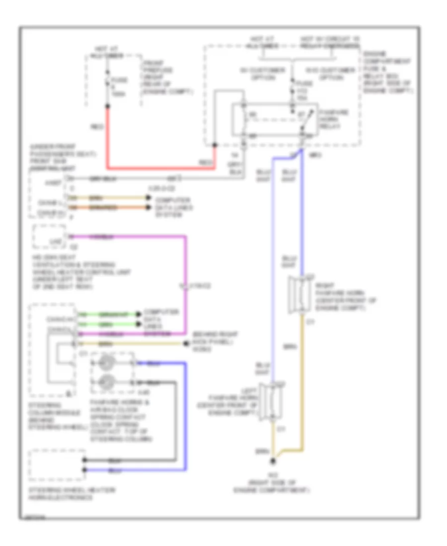
Horn Wiring Diagram for Mercedes-Benz GL350 2012
 https://portal-diagnostov.com/license.html
Automotive Electricians Portal FZCO
Automotive Electricians Portal FZCO
https://portal-diagnostov.com/license.html
https://portal-diagnostov.com/license.html
Automotive Electricians Portal FZCO
Automotive Electricians Portal FZCOList of elements for Horn Wiring Diagram for Mercedes-Benz GL350 2012:
- (behind right kick panel) w29/2
- (under front passenger's seat) front sam control unit
- A45
- Anst
- Can-b h
- Can-b l
- Can-c-h
- Can-c-l
- Computer data lines system
- Engine compartment fuse & relay box (right side of engine compt)
- Fanfare horn relay
- Fanfare horns & air bag clock spring contact (clock spring contact: top of steering column)
- Front prefuse (right rear of engine compt)
- Fuse 100a
- Fuse 15a
- Hot at all times
- Hot w/ circuit 15 relay energized
- Hs (sih) seat ventilation & steering wheel heater control unit (under left seat of 2nd seat row)
- Left fanfare horn (center front of engine compt)
- Lhz
- Mr3
- Red
- Right fanfare horn (center front of engine compt)
- Steering column module (behind steering wheel)
- Steering wheel heater/ horn electronics
- W/ customer option
- W/o customer option
- W2 (right side of engine compartment)
- X18-c2
- X25-2-c2
INSTRUMENT CLUSTER
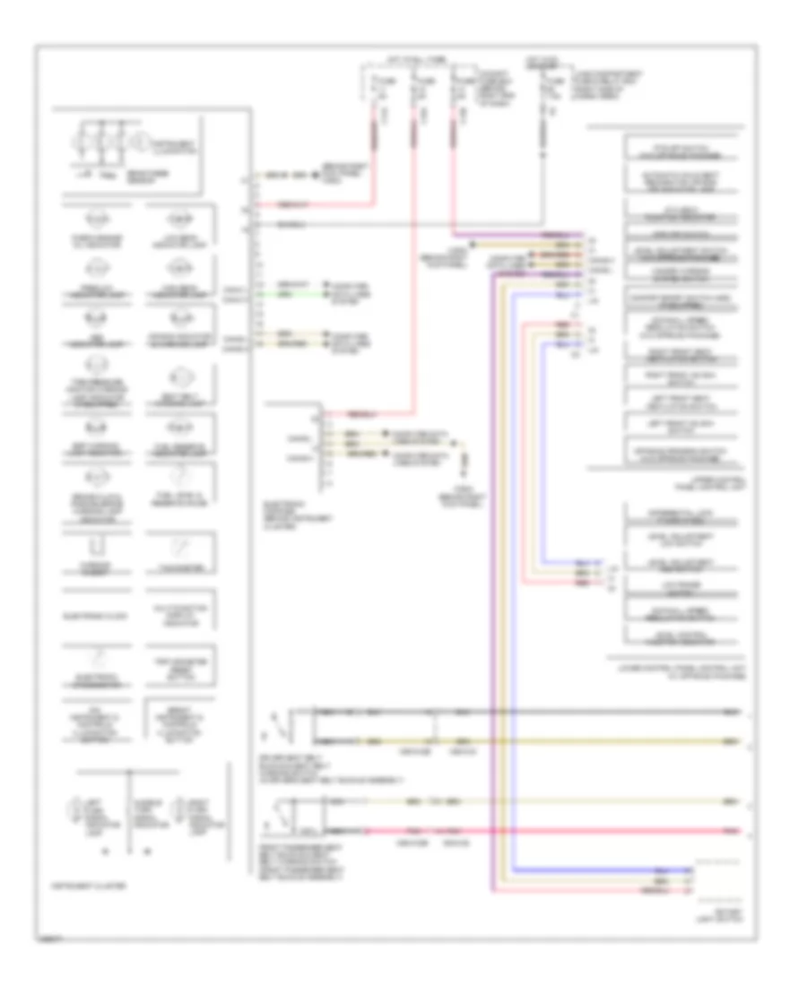
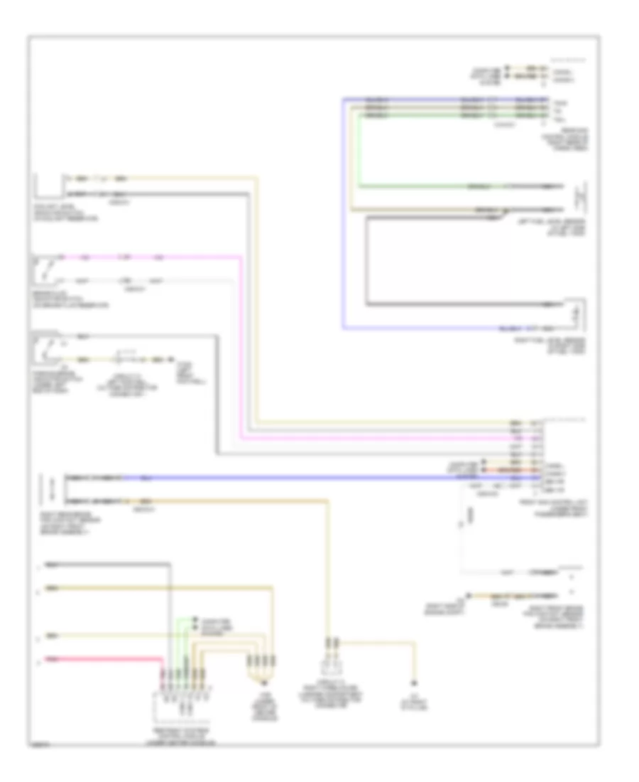
Instrument Cluster Wiring Diagram (1 of 2) for Mercedes-Benz GL350 2012
 https://portal-diagnostov.com/license.html
Automotive Electricians Portal FZCO
Automotive Electricians Portal FZCO
https://portal-diagnostov.com/license.html
https://portal-diagnostov.com/license.html
Automotive Electricians Portal FZCO
Automotive Electricians Portal FZCOList of elements for Instrument Cluster Wiring Diagram (1 of 2) for Mercedes-Benz GL350 2012:
- "check engine" mil indicator
- (behind right kick panel) w29/2
- Abs indicator lamp
- Air bag indicator & warning lamp
- Ata (edw) function indicator
- Audible turn signal indicator
- Automatic child seat recognition air bag off indicator lamp
- Brake fluid & parking brake warning lamp indicator
- Bright instrument & controls illumination button
- Brightness sensor
- C11a
- C13b
- C15a
- Can-b h
- Can-b l
- Can-c h
- Can-c l
- Cockpit fuse box (behind right end of dash)
- Comfort/sport switch (ads) (if equipped)
- Computer data lines system
- Differential lock thumb wheel
- Dim instrument & controls illumination button
- Downhill speed regulation switch
- Downhill speed regulation switch (w/o offroad package)
- Driver seat belt buckle & seat belt warning switch (in driver's seat belt buckle assembly)
- Electronic clock
- Electronic compass (behind instrument cluster)
- Electronic speedometer
- Esp off switch
- Esp warning lamp indicator
- Front passenger seat belt buckle & seat belt warning switch (front passenger seat belt buckle assembly)
- Fuel level & reserve gauge
- Fuel reserve indicator lamp
- Fuse 5a
- Fuse 7.5a
- Hazard warning system switch
- High beam indicator lamp
- Hot at all times
- Hot in on or start
- Instrument cluster
- Instrument illumination
- Left front hs (sih) switch
- Left front seat ventilation switch
- Left turn signal indicator lamp
- Level adjustment high switch
- Level adjustment low switch
- Level adjustment switch (w/o offroad package)
- Level control function indicator
- Lin
- Load compartment fuse & relay box (right side of cargo area)
- Low beam indicator lamp
- Low range switch
- Lower control panel control unit (w/ off-road package)
- Multi-function display indicator
- Nca
- Off-road program switch (w/o offroad package)
- Pnk
- Preglow indicator lamp
- Pts off switch (w/o off-road package)
- Red
- Right front hs (sih) switch
- Right front seat ventilation switch
- Right turn signal indicator lamp
- Rotary light switch
- Seat belt warning lamp
- Tachometer
- Tire pressure monitor warning lamp indicator (if equipped)
- Trip odometer reset button
- Upper control panel control unit
- W29/2 (behind right kick panel)
- Warning buzzer
- X55/3-c2
- X55/3-c2b
- X55/4-c2
- X55/4-c2b
Instrument Cluster Wiring Diagram (2 of 2) for Mercedes-Benz GL350 2012
 https://portal-diagnostov.com/license.html
Automotive Electricians Portal FZCO
Automotive Electricians Portal FZCO
https://portal-diagnostov.com/license.html
https://portal-diagnostov.com/license.html
Automotive Electricians Portal FZCO
Automotive Electricians Portal FZCOList of elements for Instrument Cluster Wiring Diagram (2 of 2) for Mercedes-Benz GL350 2012:
- Bbv hr
- Bbv vr
- Brake fluid indicator switch (on brake fluid reservoir)
- Can-b h
- Can-b l
- Can-c h
- Can-c l
- Circuit 31 left footwell voltage distributor connector 1
- Circuit 31 right wheelhouse luggage compartment voltage distributor connector
- Computer data lines system
- Coolant level indicator switch (in coolant reservoir)
- Front sam control unit (under front passenger's seat)
- Left fuel level sensor (in left side of fuel tank)
- Nca
- Parking brake indicator switch (under left end of dash)
- Pnk
- Rear sam control module (right rear of cargo area)
- Restraint systems control module (under center console)
- Right front brake pad contact sensor (on right front brake assembly)
- Right fuel level sensor (in right side of fuel tank)
- Right rear brake pad contact sensor (on right front brake assembly)
- Tg+l
- Tg+r
- Tg-
- W15/2 (left front footwell)
- W2 (right side of engine compt)
- W26 (under front of center console)
- W7 (at right "d" pillar)
- X18/3-c1
- X25/2-c1
- X25/2-c2
- X62/33-a
- X62/36
Overhead Console Wiring Diagram for Mercedes-Benz GL350 2012
 https://portal-diagnostov.com/license.html
Automotive Electricians Portal FZCO
Automotive Electricians Portal FZCO
https://portal-diagnostov.com/license.html
https://portal-diagnostov.com/license.html
Automotive Electricians Portal FZCO
Automotive Electricians Portal FZCOList of elements for Overhead Console Wiring Diagram for Mercedes-Benz GL350 2012:
- (+)
- (-)
- (not used)
- 15r
- 1st seat row interior lamp switch
- 1st seat row left interior lamp
- 1st seat row left reading lamp switch
- 1st seat row right interior lamp
- 1st seat row right reading lamp switch
- 58d
- Ambient lamp
- Automatic dimming mirror
- Can-b h
- Can-b l
- Computer data lines system
- Data
- Door contact on & off switch
- Edw
- Fuse 25a
- Garage door opener button 1
- Garage door opener button 2
- Garage door opener button 3
- Garage door opener indicator lamp
- Garage door opener transmitter unit
- Garage door opener transmitter unit (integral to interior rearview mirror unit)
- Gnd
- H (+)
- H (-)
- H sig 1
- H sig 2
- Hands-free system microphone group
- Hot at all times
- Inside rearview mirror unit
- Interior lights system
- Ki58
- Ld+
- Ld-
- Left reading lamp
- Ll l
- Ll r
- Load compartment fuse & relay box (right side of cargo area)
- Nca
- Overhead control panel control unit
- Power tops system
- Rain/light sensor (top center of windshield)
- Rear dome lamp switch
- Red
- Right reading lamp
- Roof switch
- Ta li
- Ta re
- W48/3 (right rear of cargo area)
- X18/2-c1
INTERIOR LIGHTS
Interior Lights Wiring Diagram (1 of 3) for Mercedes-Benz GL350 2012
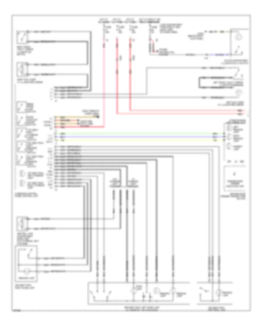 https://portal-diagnostov.com/license.html
Automotive Electricians Portal FZCO
Automotive Electricians Portal FZCO
https://portal-diagnostov.com/license.html
https://portal-diagnostov.com/license.html
Automotive Electricians Portal FZCO
Automotive Electricians Portal FZCOList of elements for Interior Lights Wiring Diagram (1 of 3) for Mercedes-Benz GL350 2012:
- (+)
- (-)
- (right rear of cargo area) w48/3
- 15r
- 1st seat row interior lamp switch
- 1st seat row left interior lamp
- 1st seat row left reading lamp switch
- 1st seat row right interior lamp
- 1st seat row right reading lamp switch
- 2nd seat row left dome lamp
- 2nd seat row right dome lamp
- 3rd seat row left dome lamp (w/ interior light package)
- 58d
- Ambient lamp
- Can-b h
- Can-b l
- Central load compartment dome lamp (w/o interior light package)
- Computer data lines system
- Data
- Dome lamp
- Door contact on/off switch
- Fuse 25a
- Fuse 5a
- Garage door opener indicator lamp
- Garage door opener transmitter switch
- Glove compartment illumination w/ switch
- Gnd
- Hot at all times
- Hot w/ circuit 15r relay energized
- Interior rear view mirror unit
- Ki 58
- Left front vanity mirror illumination switch
- Left reading lamp
- Left sun visor w/ illuminated mirror
- Ll l
- Ll r
- Load compartment fuse & relay box (right side of cargo area)
- Nca
- Overhead control panel control unit
- Power distribution system
- Reading lamp
- Rear dome lamp switch
- Red
- Right front vanity mirror illumination switch
- Right reading lamp
- Right sun visor w/ illuminated mirror
- Ta li
- Ta re
- W/ interior light package
- W/o interior light package
- W29/2 (behind right kick panel)
- X18
- X35/1
- X35/2
Interior Lights Wiring Diagram (2 of 3) for Mercedes-Benz GL350 2012
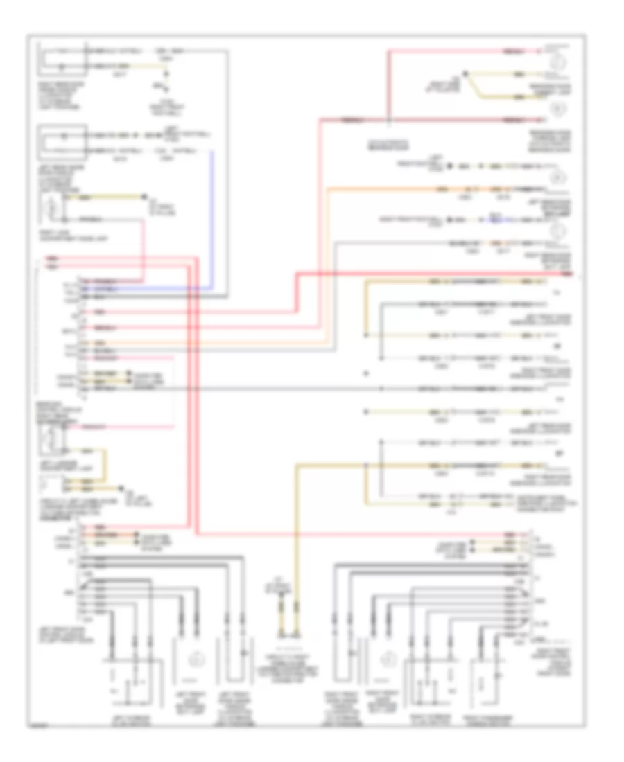 https://portal-diagnostov.com/license.html
Automotive Electricians Portal FZCO
Automotive Electricians Portal FZCO
https://portal-diagnostov.com/license.html
https://portal-diagnostov.com/license.html
Automotive Electricians Portal FZCO
Automotive Electricians Portal FZCOList of elements for Interior Lights Wiring Diagram (2 of 3) for Mercedes-Benz GL350 2012:
- (left front footwell) w15/2
- (right front footwell) w15/1
- Al(+)
- C3a
- C3b
- Can-b h
- Can-b l
- Circuit 31 left wheelhouse luggage compartment voltage distribution connector
- Circuit 31 right wheelhouse luggage compartment voltage distributor connector
- Computer data lines system
- Front passenger window switch
- Gnd
- Instrument panel ambiance illumination connecting point
- Kl (+)
- Kl 58
- Left front door ambiance illumination
- Left front door control module (in left front door)
- Left front door entrance/ exit lamp
- Left front door inside handle illumination (w/ interior light package)
- Left interior cl (zv) switch
- Left luggage compartment lamp
- Left rear door ambiance illumination
- Left rear door entrance/ exit lamp
- Left rear inside door handle illumination (w/ interior light package)
- Nca
- Rear sam control module (right rear of cargo area)
- Rear-end door ambient lamp
- Rear-end door warning lamp (w/o automatic rear-end door)
- Red
- Right front door ambiance illumination
- Right front door control module (in right front door)
- Right front door entrance/ exit lamp
- Right front door inside handle illumination (w/ interior light package)
- Right interior cl (zv) switch
- Right load compartment dome lamp
- Right rear door ambiance illumination
- Right rear door entrance/ exit lamp
- Right rear door inside handle illumination (w/ interior light package)
- Rwtl
- Tig l
- Tig r
- W/o automatic rear-end door
- W15/1 (right front footwell)
- W6 (at left "d" pillar)
- W7 (at right "d" pillar)
- W8 (right side of tailgate)
- X157/10
- X157/6
- X157/7
- X157/9
- X18
- X35/1
- X35/2
- X35/3
- X35/4
- X8/16
- X8/17
Interior Lights Wiring Diagram (3 of 3) for Mercedes-Benz GL350 2012
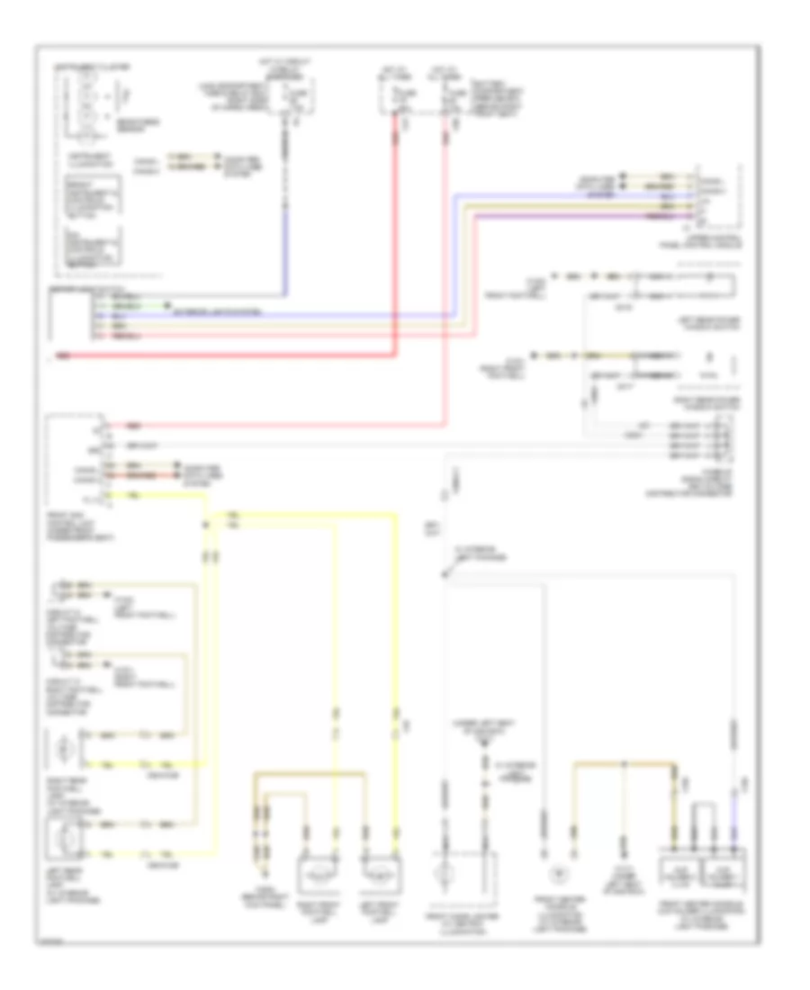 https://portal-diagnostov.com/license.html
Automotive Electricians Portal FZCO
Automotive Electricians Portal FZCO
https://portal-diagnostov.com/license.html
https://portal-diagnostov.com/license.html
Automotive Electricians Portal FZCO
Automotive Electricians Portal FZCOList of elements for Interior Lights Wiring Diagram (3 of 3) for Mercedes-Benz GL350 2012:
- (under left seat of 2nd row) w17/1
- 58d
- Battery compartment prefuse box (behind right front seat)
- Bright instrument & controls illumination button
- Brightness sensor
- C79
- C88
- Can-b h
- Can-b l
- Circuit 31 left footwell voltage distributor connector
- Circuit 31 right footwell voltage distributor connector
- Computer data lines system
- Cup holder 1 illum
- Cup holder 2 illum
- Dim instrument & controls illumination button
- Exterior lights system
- Fl (+)
- Front center console cup holder illumination (w/ interior light package)
- Front center console illumination (w/ interior light package)
- Front cigar lighter (w/ ashtray illumination)
- Front sam control unit (under front passenger's seat)
- Fuse 60a
- Fuse 7.5a
- Fuse 70a
- Hot at all times
- Hot w/ circuit 15 relay energized
- Instrument cluster
- Instrument illumination
- Left front footwell lamp
- Left rear footwell lamp (w/ interior light package)
- Left rear power window switch
- Lin
- Load compartment fuse & relay box (right side of cargo area)
- Nca
- Red
- Right front footwell lamp
- Right rear footwell lamp (w/ interior light package)
- Right rear power window switch
- Rotary light switch
- Upper control panel control module
- W/ interior light package
- W15/1 (right front footwell)
- W15/2 (left front footwell)
- W17/1 (under left seat of 2nd row)
- W29/2 (behind right kick panel)
- Wake-up signal/circuit 58d voltage distributor connector
- X156
- X18
- X29/6-c1
- X35/3
- X35/4
- X55/3-c4b
- X55/4-c4b
- X8/16
- X8/17
MEMORY SYSTEMS
Driver"s Memory Seat Wiring Diagram for Mercedes-Benz GL350 2012
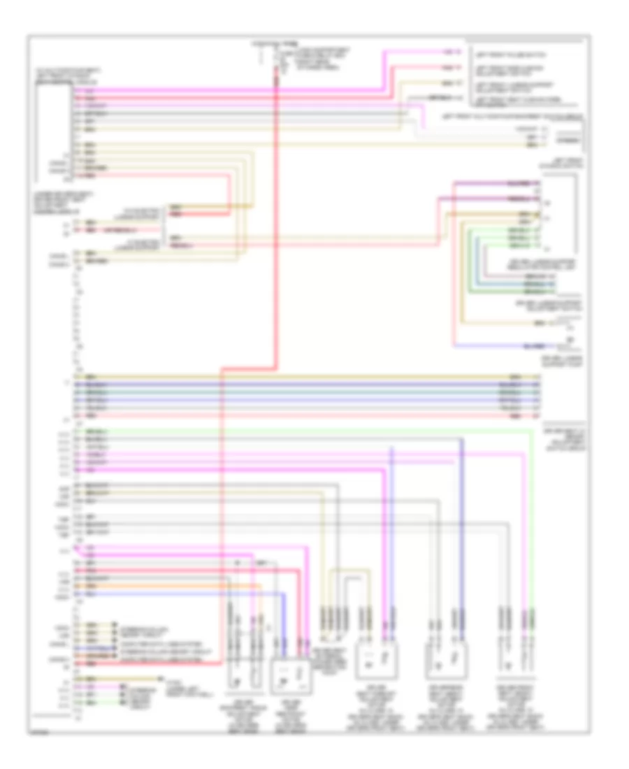 https://portal-diagnostov.com/license.html
Automotive Electricians Portal FZCO
Automotive Electricians Portal FZCO
https://portal-diagnostov.com/license.html
https://portal-diagnostov.com/license.html
Automotive Electricians Portal FZCO
Automotive Electricians Portal FZCOList of elements for Driver"s Memory Seat Wiring Diagram for Mercedes-Benz GL350 2012:
- (+)
- (-)
- (under driver's seat) driver front seat adjustment control module
- (w/ multicontour seat) left front dynamic seat control module
- Can-b h
- Can-b l
- Computer data lines system
- Driver backrest angle adjustment motor (in driver's seat back)
- Driver front seat height adjustment motor (ml-class: in driver's seat back) (gl-class: under driver's front seat)
- Driver head restraint motor (in driver's seat back)
- Driver lumbar support adjustment switch
- Driver lumbar support pump
- Driver lumbar support regulator control unit
- Driver rear seat height adjustment motor (ml-class: in driver's seat back) (gl-class: under driver's front seat)
- Driver seat external power feed separation point
- Driver seat fore/aft adjustment motor (ml-class: in driver's seat back) (gl-class: under driver's front seat)
- Driver seat w/ memory adjustment switch group
- Dynamic
- Fuse 30a
- H (+)
- H (-)
- Hoch
- Hot at all times
- Left front dynamic switch
- Left front lumbar support adjustment switch
- Left front multicontour backrest switch group
- Left front pulse switch
- Left front seat cushion fore/ aft switch
- Left front side cushion adjustment switch
- Load compartment fuse & relay box (right rear of cargo area)
- Nca
- Pnk
- Red
- Steering column memory circuit
- Tief
- Vor
- W/ electric lumbar support
- W/o electric lumbar support
- W15/2 (under left front footwell)
- Zur
Memory Mirrors Wiring Diagram for Mercedes-Benz GL350 2012
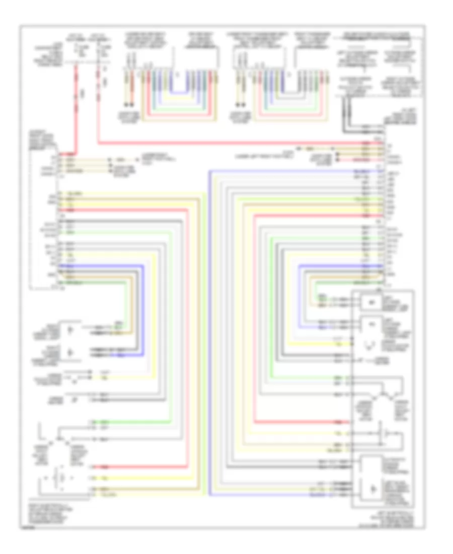 https://portal-diagnostov.com/license.html
Automotive Electricians Portal FZCO
Automotive Electricians Portal FZCO
https://portal-diagnostov.com/license.html
https://portal-diagnostov.com/license.html
Automotive Electricians Portal FZCO
Automotive Electricians Portal FZCOList of elements for Memory Mirrors Wiring Diagram for Mercedes-Benz GL350 2012:
- (+)
- (-)
- (in left front door) left front door control module
- (in right front door) right front door control module
- (under driver seat) driver front seat adjustment control module w/ memory
- (under front passenger seat) front passenger front seat adjustment control unit w/ memory
- (under right front footwell) w15/1
- Automatic dimming mirror (if equipped)
- C3a
- Can b h
- Can b l
- Can-b h
- Can-b l
- Computer data lines system
- Driver power window & outside mirror adjustment switch group
- Driver seat w/ memory adjustment switch group
- Front passenger
- Fuse 25a
- Gnd
- Hot at all times
- Led
- Led 31
- Left blind spot assist readiness & warning indicator (if equipped)
- Left electrically adjustable & heated exterior mirror (ml-class: on driver's door)
- Left outside mirror adjustment selection switch (w/ mirror fold out)
- Left outside mirror ambient lamp (if equipped)
- Left outside mirror turn signal lamp
- Load compartment fuse & relay box (right rear of cargo area)
- Mirror fold-in motor (if equipped)
- Mirror heater
- Mirror in/out adjust- ment
- Mirror up/down adjust- ment
- Motor
- Nca
- Outside mirror adjustment rocker switch
- Outside mirror fold in/ fold out switch (w/ mirror fold out)
- Red
- Right electrically adjustable & heated exterior mirror (ml-class: on front passenger door)
- Right outside mirror adjustment selection switch (w/ mirror fold out)
- Right outside mirror ambient lamp (if equipped)
- Right outside mirror turn signal lamp
- Seat w/ memory adjustment switch group
- Sh (+)
- Sh (-)
- Sig
- Sv-m1
- Sv-m1m2
- Sv-m2
- W15/2 (under left front footwell)
- X35/1
- X35/2
Passenger"s Memory Seat Wiring Diagram for Mercedes-Benz GL350 2012
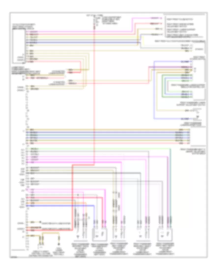 https://portal-diagnostov.com/license.html
Automotive Electricians Portal FZCO
Automotive Electricians Portal FZCO
https://portal-diagnostov.com/license.html
https://portal-diagnostov.com/license.html
Automotive Electricians Portal FZCO
Automotive Electricians Portal FZCOList of elements for Passenger"s Memory Seat Wiring Diagram for Mercedes-Benz GL350 2012:
- (+)
- (-)
- (h+)
- (under front passenger's seat) front passenger front seat adjustment control module
- (w/ multicontour seat) right front dynamic seat control module
- Can-b h
- Can-b l
- Circuit 31 right footwell voltage distributor connector
- Computer data lines system
- Dynamic
- Front passenger backrest angle adjustment motor (in front passenger's seat back)
- Front passenger front seat height adjustment motor (under front passenger's seat)
- Front passenger head restraint motor (in front passenger's seat back)
- Front passenger lumbar support adjustment switch
- Front passenger lumbar support pump
- Front passenger lumbar support regulator control unit
- Front passenger rear seat height adjustment motor (under front passenger's seat)
- Front passenger seat fore/aft adjustment motor (under front passenger's seat)
- Front passenger seat w/ memory adjustment switch group
- Fuse 30a
- H(+)
- H(-)
- Hoch
- Hot at all times
- Load compartment fuse & relay box (right rear of cargo area)
- Nca
- Pnk
- Red
- Right front dynamic switch
- Right front lumbar support adjustment switch
- Right front multicontour backrest switch group
- Right front pulse switch
- Right front seat cushion fore/ aft adjustment switch
- Right front side bolsters adjustment switch
- Tief
- Vor
- W/ electric lumbar support
- W/o electric lumbar support
- W15/1 (under right front footwell)
- X54/32
- Zur
Steering Column Memory Wiring Diagram for Mercedes-Benz GL350 2012
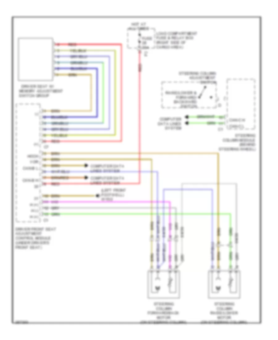 https://portal-diagnostov.com/license.html
Automotive Electricians Portal FZCO
Automotive Electricians Portal FZCO
https://portal-diagnostov.com/license.html
https://portal-diagnostov.com/license.html
Automotive Electricians Portal FZCO
Automotive Electricians Portal FZCOList of elements for Steering Column Memory Wiring Diagram for Mercedes-Benz GL350 2012:
- (+)
- (-)
- (left front footwell) w15/2
- Can-b h
- Can-b l
- Can-c h
- Can-c l
- Computer data lines system
- Driver front seat adjustment control module (under driver's front seat)
- Driver seat w/
- Fuse 30a
- H (+)
- H (-)
- Hoch
- Hot at all times
- Load compartment fuse & relay box (right side of cargo area)
- Memory adjustment
- Raise/lower & forward/ backward switch
- Red
- Steering column adjustment switch
- Steering column forward/back motor (on steering column)
- Steering column module (behind steering wheel)
- Steering column raise/lower motor (on steering column)
- Switch group
- Vor
- X4/39
NAVIGATION
Blind Spot Information System Wiring Diagram for Mercedes-Benz GL350 2012
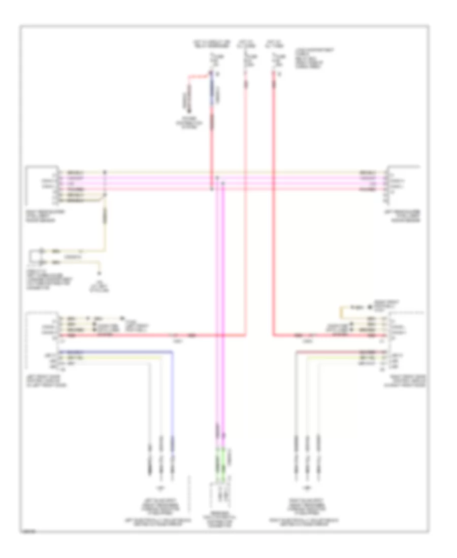 https://portal-diagnostov.com/license.html
Automotive Electricians Portal FZCO
Automotive Electricians Portal FZCO
https://portal-diagnostov.com/license.html
https://portal-diagnostov.com/license.html
Automotive Electricians Portal FZCO
Automotive Electricians Portal FZCOList of elements for Blind Spot Information System Wiring Diagram for Mercedes-Benz GL350 2012:
- (right front footwell) w15/1
- Can-b h
- Can-b l
- Can-c h
- Can-c l
- Circuit 31 left wheelhouse luggage compartment voltage distributor connector
- Computer data lines system
- Fuse 25a
- Fuse 5a
- Hot at all times
- Hot w/ circuit 15r relay energized
- Led
- Led 31
- Left blind spot assist readiness warning indicator (if equipped)
- Left electrically adjustable & heated outside mirrior
- Left front door control module (in left front door)
- Left rear bumper intelligent radar sensor
- Load compartment fuse & relay box (right side of cargo area)
- Nca
- Pnk/red
- Power distribution system
- Rear end can c potential distributor connector
- Red
- Right blind spot assist readiness warning indicator (if equipped)
- Right electrically adjustable & heated outside mirrior
- Right front door control module (in right front door)
- Right rear bumper intelligent radar sensor
- W15/2 (left front footwell)
- W6 (at left "d" pillar)
- X35/1
- X35/2
- X35/29-c4
COMAND Actuation Wiring Diagram (1 of 2) for Mercedes-Benz GL350 2012
 https://portal-diagnostov.com/license.html
Automotive Electricians Portal FZCO
Automotive Electricians Portal FZCO
https://portal-diagnostov.com/license.html
https://portal-diagnostov.com/license.html
Automotive Electricians Portal FZCO
Automotive Electricians Portal FZCOList of elements for COMAND Actuation Wiring Diagram (1 of 2) for Mercedes-Benz GL350 2012:
- (not used)
- (pin 5-8 not used)
- Can-b h
- Can-b l
- Circuit 31 left rear seat voltage distributor connector
- Comand operating, display & control module
- Computer data lines system
- Emergency call system control unit (under left seat of 2nd row)
- Fm rear window antenna amplifier (left side of tailgate)
- Fuse 20a
- Fuse 5a
- Gps
- Gps antenna splitter (under left seat of 2nd seat row)
- Hands-free system microphone group
- Hl (+)
- Hl (-)
- Hot at all times
- Hr (+)
- Hr (-)
- Interface connector 2 (if equipped)
- Load compartment fuse & relay box (right side of cargo area)
- Media
- Most
- Most in
- Most out
- Mute
- Nca
- Pnk
- Radio antenna interference filter
- Rear camera circuit
- Rear sam control module (right rear of cargo area)
- Red
- Roof antenna module (center rear of roof)
- Sound systems
- Vl (+)
- Vl (-)
- Vr (+)
- Vr (-)
- W/o high-definition tuner
- W17/1 (under left seat of 2nd row)
- W29/8 (top of left "d" pillar)
- Wake up
- Walkman separation point (if equipped)
- X18/2-c3
- X18/67
COMAND Actuation Wiring Diagram (2 of 2) for Mercedes-Benz GL350 2012
 https://portal-diagnostov.com/license.html
Automotive Electricians Portal FZCO
Automotive Electricians Portal FZCO
https://portal-diagnostov.com/license.html
https://portal-diagnostov.com/license.html
Automotive Electricians Portal FZCO
Automotive Electricians Portal FZCOList of elements for COMAND Actuation Wiring Diagram (2 of 2) for Mercedes-Benz GL350 2012:
- Button + & -, setting specific functions & volume control
- Can-c h
- Can-c l
- Computer data lines system
- Fanfare horns & air bag clock spring contact (fanfare horns: center front of engine compt) (air bag clock spring contact: top of steering column)
- Left front door speaker
- Left front door tweeter
- Left rear door speaker
- Left rear door tweeter
- Lin
- Multi-function steering wheel electronics unit
- Red
- Right front door speaker
- Right front door tweeter
- Right multi-function steering wheel button group
- Right rear door speaker
- Right rear door tweeter
- Steering column module (behind steering wheel)
- W/o sound system
- X35/1
- X35/2
- X35/3
- X35/4
Emergency Call Wiring Diagram for Mercedes-Benz GL350 2012
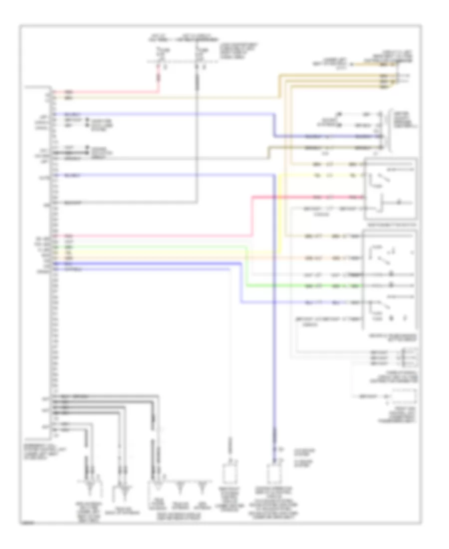 https://portal-diagnostov.com/license.html
Automotive Electricians Portal FZCO
Automotive Electricians Portal FZCO
https://portal-diagnostov.com/license.html
https://portal-diagnostov.com/license.html
Automotive Electricians Portal FZCO
Automotive Electricians Portal FZCOList of elements for Emergency Call Wiring Diagram for Mercedes-Benz GL350 2012:
- (or nca)
- (under left seat of 2nd row) w17/1
- 15r
- Ant
- Can-d h
- Can-d l
- Center cockpit speaker (centerfill)
- Circuit 31 left rear seat voltage distributor connector
- Comand actuation circuit
- Comand operating display & control module (w/o sound system) sound system amplifier (w/ sound system) (sound system amplifier: under driver's seat)
- Computer data lines system
- Crash
- Ec led
- Ecs
- Emergency call system control unit (under left seat of 2nd row)
- Front sam control unit (under front passenger's seat)
- Fuse 5a
- Gps antenna
- Gps antenna splitter (under left seat of 2nd seat row)
- Hot at all times
- Hot w/ circuit 15r relay energized
- Ic led
- Ics
- Load compartment fuse & relay box (right side of cargo area)
- Lsp +
- Lsp -
- Mb-info & telediagnosis button group
- Mic 1
- Mic gnd
- Mute
- Nca
- Pnk
- Red
- Restraint systems control module (under center console)
- Roof antenna module (center rear of roof)
- Sos pushbutton switch
- Sound systems
- Tdc led
- Tele aid antenna
- Tele aid back up antenna
- Tele phone antenna
- W/ sound system
- W/o sound system
- Wake-up signal/ circuit 58d voltage distributor connector
- X18
- X18/2-c2
- X29/6-c3
Parktronic Wiring Diagram for Mercedes-Benz GL350 2012
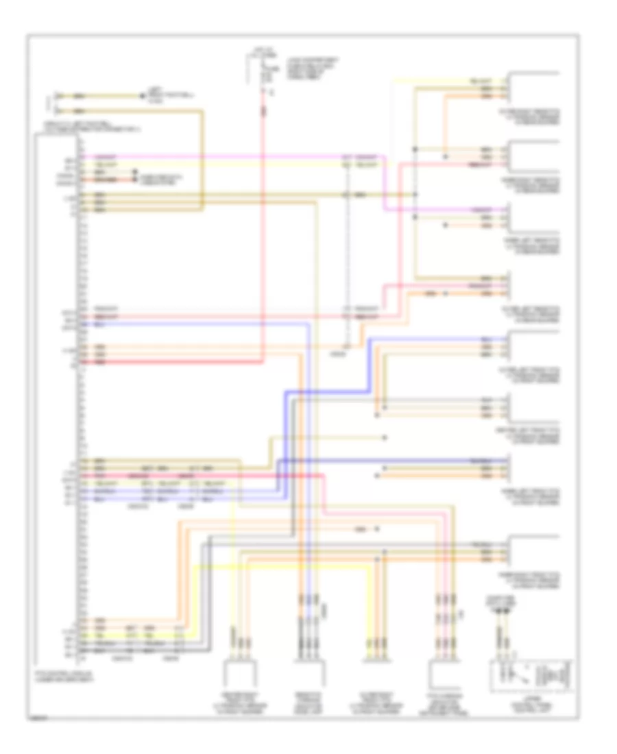 https://portal-diagnostov.com/license.html
Automotive Electricians Portal FZCO
Automotive Electricians Portal FZCO
https://portal-diagnostov.com/license.html
https://portal-diagnostov.com/license.html
Automotive Electricians Portal FZCO
Automotive Electricians Portal FZCOList of elements for Parktronic Wiring Diagram for Mercedes-Benz GL350 2012:
- (+) sh
- (+) sv
- (-) sh
- (-) sv
- (left front footwell) w15/2
- Can-b h
- Can-b l
- Center left front pts ultrasonic sensor (in front bumper)
- Center right front pts ultrasonic sensor (in front bumper)
- Circuit 31 left footwell voltage distributor connector (1)
- Computer data lines system
- Data
- Fuse 5a
- Hot at all times
- Inner left front pts ultrasonic sensor (in front bumper)
- Inner left rear pts ultrasonic sensor (in rear bumper)
- Inner right front pts ultrasonic sensor (in front bumper)
- Inner right rear pts ultrasonic sensor (in rear bumper)
- Load compartment fuse & relay box (right side of cargo area)
- Nca
- Outer left front pts ultrasonic sensor (in front bumper)
- Outer left rear pts ultrasonic sensor (in rear bumper)
- Outer right front pts ultrasonic sensor (in front bumper)
- Outer right rear pts ultrasonic sensor (in rear bumper)
- Package) road off (w/o switch pts off
- Pnk
- Pts control module (under driver's seat)
- Pts warning indicator, driver side instrument panel
- Rear pts warning indicator dome lamp
- Red
- S1 v
- S10 h
- S2 v
- S3 v
- S4 v
- S5 v
- S6 v
- S7 h
- S8 h
- S9 h
- Upper control panel control unit
- X18
- X25/2-c2
- X26/36
- X35/26
- X35/28
Rear Camera Wiring Diagram for Mercedes-Benz GL350 2012
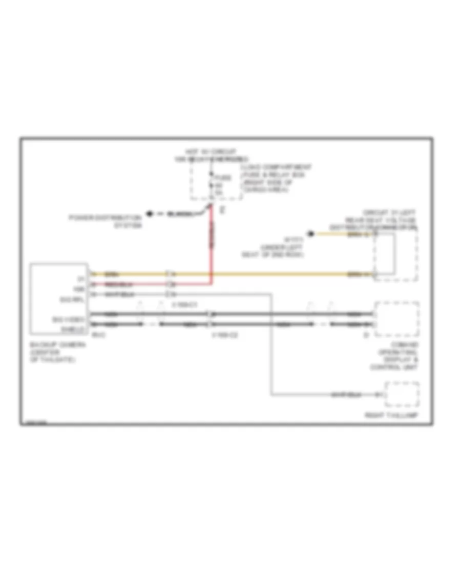 https://portal-diagnostov.com/license.html
Automotive Electricians Portal FZCO
Automotive Electricians Portal FZCO
https://portal-diagnostov.com/license.html
https://portal-diagnostov.com/license.html
Automotive Electricians Portal FZCO
Automotive Electricians Portal FZCOList of elements for Rear Camera Wiring Diagram for Mercedes-Benz GL350 2012:
- 15r
- Backup camera (center of tailgate)
- Circuit 31 left rear seat voltage distributor connector
- Comand operating, display & control unit
- Fuse 5a
- Hot w/ circuit 15r relay energized
- Load compartment fuse & relay box (right side of cargo area)
- Nca
- Nca s
- Power distribution system
- Right taillamp
- Rvc
- Shield
- Sig rfl
- Sig video
- W17/1 (under left seat of 2nd row)
- X169-c1
- X169-c2
POWER DISTRIBUTION
Power Distribution Wiring Diagram (1 of 4) for Mercedes-Benz GL350 2012
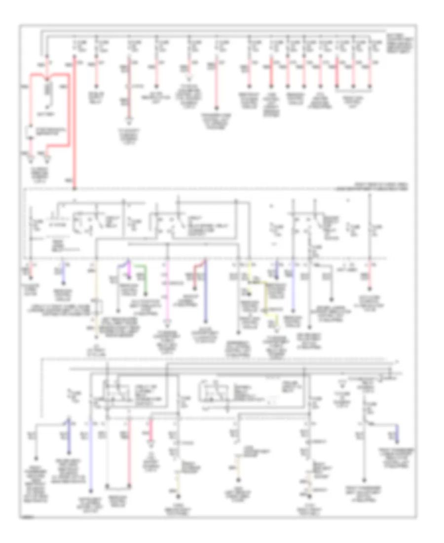 https://portal-diagnostov.com/license.html
Automotive Electricians Portal FZCO
Automotive Electricians Portal FZCO
https://portal-diagnostov.com/license.html
https://portal-diagnostov.com/license.html
Automotive Electricians Portal FZCO
Automotive Electricians Portal FZCOList of elements for Power Distribution Wiring Diagram (1 of 4) for Mercedes-Benz GL350 2012:
- (not used)
- (right rear of cargo area) load compartment fuse & relay box
- 87a
- Ac air recirculation unit
- Activated charcoal filter shutoff valve
- Backup
- Battery
- Battery compartment prefuse box (behind right front seat)
- C78
- C79
- C80
- C81 red
- C82
- C83
- C84
- C85
- C86
- C88
- C89
- C90
- C91
- Camera (if equipped)
- Circuit 15r 2/ spare 1 relay (change over contact)
- Circuit 15r relay
- Circuit 31 right wheel house luggage compartment voltage distributor connector
- Circuit relay/spare 1 relay (change over contact)
- Driver lumbar support regulator control unit (if equipped)
- Driver neck- pro head restraint solenoid (w/ crash active head restraints)
- Driver seat adjustment switch (if equipped)
- Emergency call system control unit (if equipped)
- Front interior socket
- Front passenger lumbar support regulator control unit (if equipped)
- Front passenger neck-pro head restraint solenoid (w/ crash active head restraints)
- Front passenger seat adjustment switch (if equipped)
- Front sam control unit
- Fuse 100a
- Fuse 10a
- Fuse 150a
- Fuse 15a
- Fuse 20a
- Fuse 30a
- Fuse 40a
- Fuse 5a
- Fuse 60a
- Fuse 7.5a
- Fuse 70a
- Glove compartment illumination w/ switch
- Instrument cluster & rotary light switch
- Left rear bumper intelligent radar sensor & right rear bumper intelligent radar sensor
- Load compartment socket
- Multicontour seat pneumatic pump (if equipped)
- Pnk
- Ptc heater booster (if equipped)
- Pyrotechnical separator
- Rear sam control module
- Rear sam control module & front sam control module
- Rear wiper relay
- Red
- Restraint systems control module
- Right 2nd seat row socket
- Socket circuit 15r relay (w/ run-on)
- Spare 2 relay (normally open contact)
- Tailgate wiper motor
- To 115v socket (diagram 3 of 4)
- To cockpit fuse box (diagram 4 of 4)
- To dc/ac converter control unit (115v socket) (diagram 3 of 4)
- To engine compartment fuse & relay box (diagram 3 of 4)
- To front prefuse (diagram 3 of 4)
- To fuse (diagram 3 of 4)
- To fuse pump relay (diagram 2 of 4)
- Trailer circuit 30 relay
- Transfer case control unit (w/ offroad package)
- W15/1 (right front footwell)
- W29/2 (behind right kick panel)
- W6/6 (left rear of cargo area floor)
- W7 (at right "d" pillar)
- Wss control unit (weight sensing system)
- X18-c2
- X25/2-c2 d4
- X25/2-c2 h2
- X29/6-c1
- X2916-c1
Power Distribution Wiring Diagram (2 of 4) for Mercedes-Benz GL350 2012
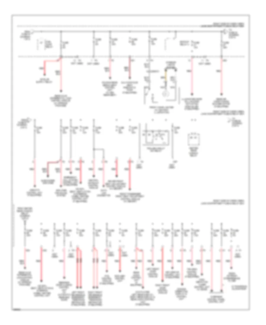 https://portal-diagnostov.com/license.html
Automotive Electricians Portal FZCO
Automotive Electricians Portal FZCO
https://portal-diagnostov.com/license.html
https://portal-diagnostov.com/license.html
Automotive Electricians Portal FZCO
Automotive Electricians Portal FZCOList of elements for Power Distribution Wiring Diagram (2 of 4) for Mercedes-Benz GL350 2012:
- (not used)
- (right side of cargo area) load compartment fuse & relay box
- 87a
- Airmatic control unit (if equipped)
- Amplifier for sound system
- Backup relay 2
- Central gateway control module
- Comand operating, display & control unit
- Data link connector
- Driver front seat adjustment control module (w/ memory)
- Dvd player, left rear display, right rear display & rear audio control unit (if equipped)
- Emergency call system control unit (if equipped)
- Folding rear bench seat control unit (w/ 3rd rear seat)
- From h fuse 43 (diagram 1 0f 4)
- From heated rear window relay (diagram 2 of 4)
- From j fuse 67 (diagram 2 0f 4)
- Front cigar lighter (w/ ashtray illumination)
- Front passenger front seat adjustment control module (w/ memory)
- Fuel pump relay
- Fuse 10a
- Fuse 15a
- Fuse 25a
- Fuse 30a
- Fuse 40a
- Fuse 5a
- Fuse 7.5a
- Heated rear window relay
- High- definition tuner control unit (w/ sdar)
- Hs (sih), seat ventilation & steering wheel heater control unit
- Hs (sih), seat ventilation & steering wheel heater control unit (if equipped)
- Illuminated door sill molding actuation module led (if equipped)
- Interior lights system
- Keyless go control unit (if equipped)
- Left front door control module
- Left front reversible emergency tensioning retractor (if equipped)
- Ms1
- Ms2
- Ms3
- Ms4
- Ms7
- Multicontour seat pneumatic pump (if equipped)
- Nca
- Overhead control panel control unit
- Pts control module (if equipped)
- Radio antenna interference filter
- Rcp (hbf) control unit
- Rear air conditioning blower motor (if equipped)
- Rear audio control unit (if equipped)
- Rear axle differential lock control module (w/ offroad package)
- Rear-end door closing control unit (w/ automatic rear end door)
- Red
- Right front door control module
- Right front reversible emergency tensioning retractor (if equipped)
- Subwoofer amplifier
- To fuse 32 (diagram 2 of 4)
- To fuse 69 (diagram 2 of 4)
- Tpm (rdk) control module (if equipped)
- Trailer circuit 30x relay
- W/ panoramic sliding roof
- X29/6-c1
Power Distribution Wiring Diagram (3 of 4) for Mercedes-Benz GL350 2012
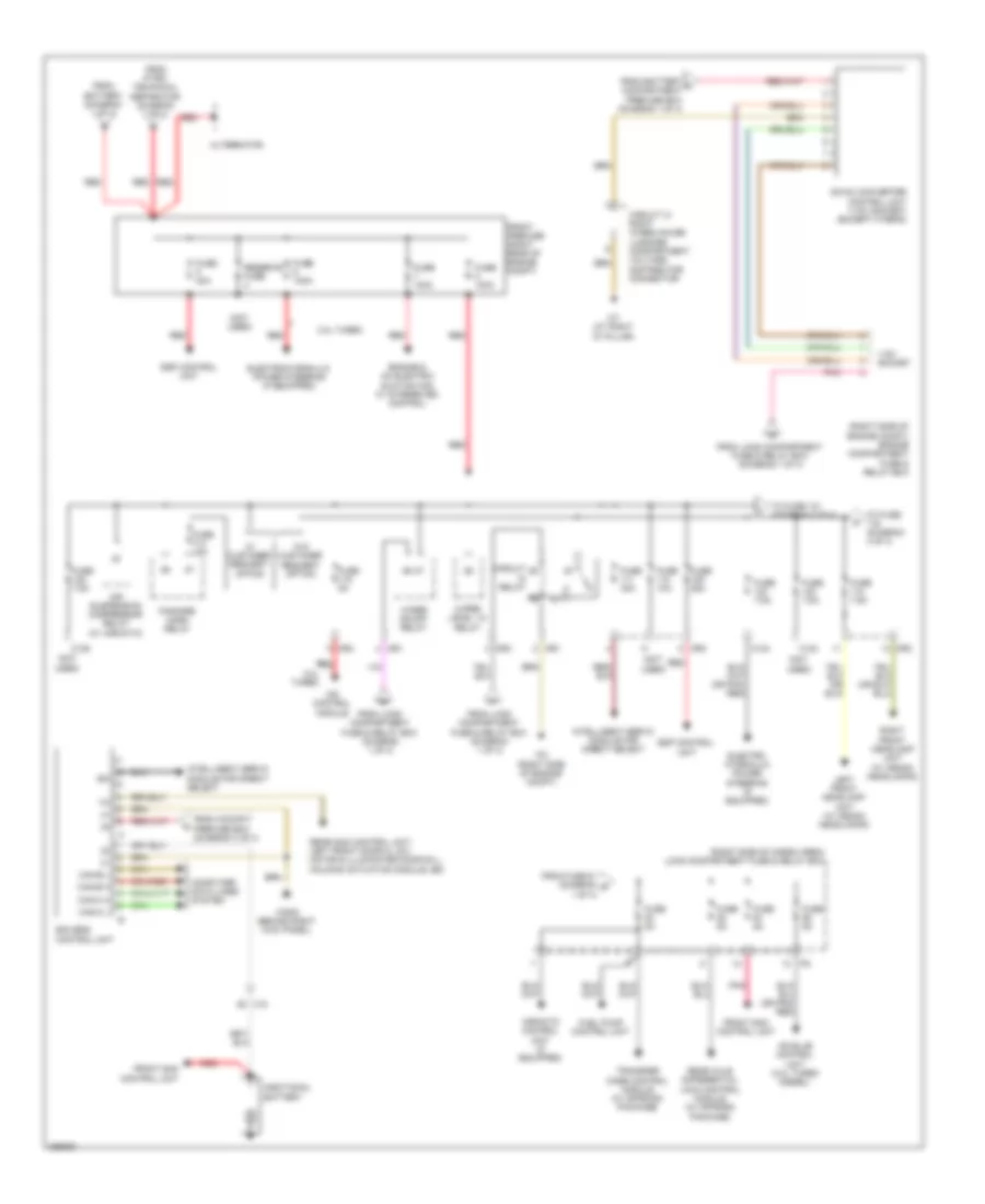 https://portal-diagnostov.com/license.html
Automotive Electricians Portal FZCO
Automotive Electricians Portal FZCO
https://portal-diagnostov.com/license.html
https://portal-diagnostov.com/license.html
Automotive Electricians Portal FZCO
Automotive Electricians Portal FZCOList of elements for Power Distribution Wiring Diagram (3 of 4) for Mercedes-Benz GL350 2012:
- (not used)
- (right side of cargo area) load compartment fuse & relay box
- (right side of engine compt) engine compartment fuse & relay box
- (w/ airmatic)
- 115v socket
- 3.0l turbo
- Additional battery
- Air suspension compressor relay
- Airmatic control unit (if equipped)
- Alternator
- C123
- C124
- C125
- Can-b h
- Can-b l
- Can-c h
- Can-c l
- Cdi control module
- Circuit
- Circuit 31 right wheelhouse luggage compartment voltage distributor connector
- Computer data lines system
- Dc/ac converter control unit (115v socket) (except hybrid)
- Eis (ezs) control unit
- Electro hydraulic power steering (if equipped)
- Electrohydraulic power steering (if equipped)
- Engine & ac electric suction fan w/ integrated control
- Esp control unit
- Fanfare horn relay
- From battery (diagram 1 of 4)
- From battery c compartment prefuse box (diagram 1 0f 4)
- From cockpit prefuse box (diagram 4 of 4)
- From fuse 51 (diagram r 1 of 4)
- From load compartment fuse & relay box (diagram 1 0f 4)
- From load compartment fuse & relay box (diagram 1 of 4)
- From pyro- technical separator (diagram 1 of 4)
- Front prefuse (right rear of engine compt)
- Front sam control unit
- Fuel pump control unit
- Fuse 100a
- Fuse 10a
- Fuse 15a
- Fuse 25a
- Fuse 30a
- Fuse 40a
- Fuse 5a
- Fuse 7.5a
- Intelligent servo module for direct select
- Ism
- Left front headlamp unit (w/ xenon headlamps)
- Mr1
- Mr3
- Mr4
- Pnk
- Rear axle differential lock control module (w/ offroad package)
- Rear sam control unit, left front door cl (zv) motor & illuminated door sill molding actuation module led
- Red
- Relay
- Reserve fuse
- Right front headlamp unit (w/ xenon headlamps)
- To fuse (diagram 4 of 4)
- To fuse 121 (diagram 4 of 4)
- Transfer case control module (w/ offroad package)
- W/ customer request option
- W/o customer request option
- W2 (right side of engine compt)
- W29/2 (behind right kick panel)
- W7 (at right "d" pillar)
- Wiper level 1/2 relay
- Wiper on/off relay
- X18
Power Distribution Wiring Diagram (4 of 4) for Mercedes-Benz GL350 2012
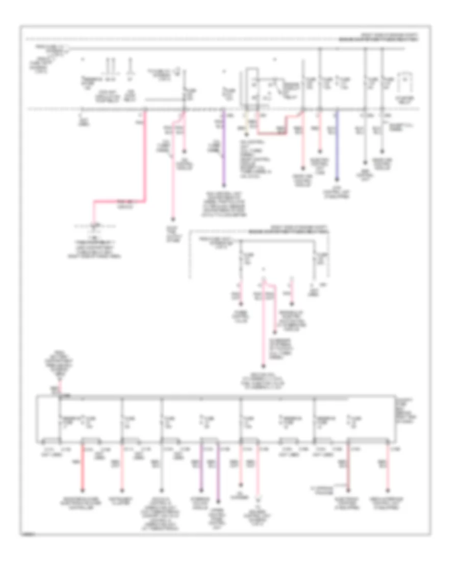 https://portal-diagnostov.com/license.html
Automotive Electricians Portal FZCO
Automotive Electricians Portal FZCO
https://portal-diagnostov.com/license.html
https://portal-diagnostov.com/license.html
Automotive Electricians Portal FZCO
Automotive Electricians Portal FZCOList of elements for Power Distribution Wiring Diagram (4 of 4) for Mercedes-Benz GL350 2012:
- (not used)
- (right side of engine compt) engine compartment fuse & relay box
- 3.0l turbo diesel
- Acc (kla) control & operating unit (w/o thermotronic) comfort acc (kla) control & operating unit (w/ thermotronic)
- Air pump relay
- Booster blower electronic blower controller
- C10a
- C10b
- C11a
- C11b
- C12a
- C12b
- C13a
- C13b
- C14a
- C14b
- C15a
- C15b
- C16a
- C16b
- C17a
- C17b
- C18a
- C18b
- C5e
- Cd changer
- Cdi control module
- Cdi control unit (3.0l turbo diesel) me-sfi control module (except 3.0l turbo diesel & 4.6l & 5.5l)
- Cockpit fuse box (behind right end of dash)
- Coolant circulation pump relay
- Dtr control unit (if equipped)
- Electric control unit (vgs)
- Electronic compass (if equipped)
- Engine & ac electric suction fan w/ integrated module
- Engine circuit relay
- Esp control unit
- Except 3.0l diesel
- From battery compartment prefuse box (diagram 1 of 4)
- From fuse 105 (diagram o 4 of 4)
- From fuse 112 (diagram m 3 of 4)
- From l fuse 109 (diagram 3 of 4)
- Fuel pump relay
- Fuse 10a
- Fuse 15a
- Fuse 20a
- Fuse 5a
- Fuse 7.5a
- Glow time output stage
- Ignition coil cylinders 2, 3, 5 & 8, fuel injection valve cylinder's 2, 3, & 8
- Instrument cluster
- Load compartment fuse & relay box (right side of cargo area)
- Me-sfi (me) control module
- Media interface control unit (if equipped)
- Mr1
- Mr2
- Mr3
- Mr4
- Nox control unit downstream of diesel particulate filter & nox sensor downstream of scr catalytic converter
- O2 sensor up stream of twc(kat) (3.0l turbo diesel)
- Pnk
- Purge control valve
- Red
- Reserve fuse
- Starter relay
- Steering column module
- To eis (ezs) control unit (diagram 3 of 4)
- To fuse 101 (diagram 4 of 4)
- Upper control panel control unit
- W/ offroad package
- X25/2-c2
POWER DOOR LOCKS
Automatic Door Locks Wiring Diagram (1 of 2) for Mercedes-Benz GL350 2012
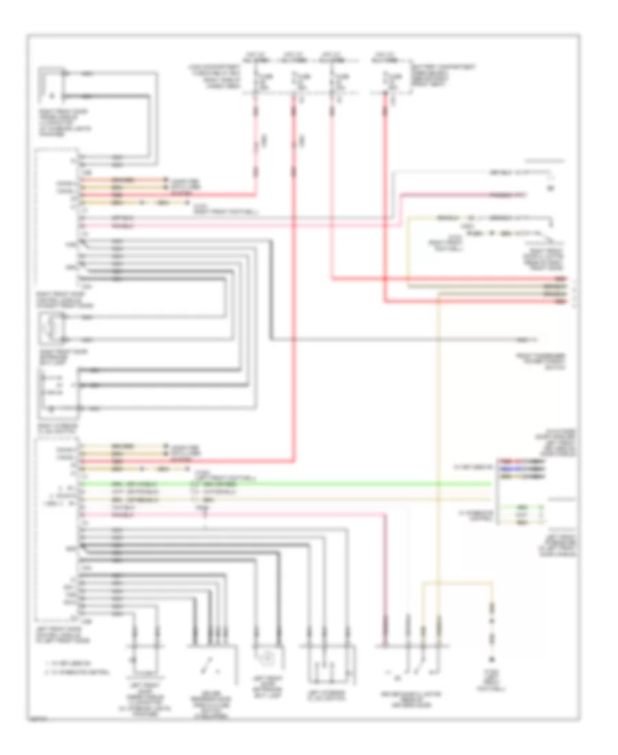 https://portal-diagnostov.com/license.html
Automotive Electricians Portal FZCO
Automotive Electricians Portal FZCO
https://portal-diagnostov.com/license.html
https://portal-diagnostov.com/license.html
Automotive Electricians Portal FZCO
Automotive Electricians Portal FZCOList of elements for Automatic Door Locks Wiring Diagram (1 of 2) for Mercedes-Benz GL350 2012:
- (in outside door handles) left front keyless go door handle
- (or red)
- (right side of cargo area)
- Battery compartment prefuse box (behind right front seat)
- C3a
- C3b
- C79
- Can-b h
- Can-b l
- Computer data lines system
- Driver door cl motor (rear of driver's door)
- Driver rear-end door open & close switch (if equipped)
- Front passenger power window switch
- Fuse 25a
- Fuse 30a
- Fuse 60a
- Gnd
- Hot at all times
- Ir +
- Ir -
- Ir data
- Ki58
- Left front door control module (in left front door)
- Left front door entrance/ exit lamp
- Left front door inside handle illumination (w/ interior lights package)
- Left front ir receiver (in left front door handle)
- Left interior cl (zv) switch
- Load compartment fuse & relay box
- Nca
- Red
- Right front door cl motor (rear of right front door)
- Right front door control module (in right front door)
- Right front door entrance/ exit lamp
- Right front door inside handle illumination (w/ interior lights package)
- Right interior cl (zv) switch
- Sig 1
- Sig 2
- W/ ir remote control
- W/ keyless go
- W15/1 (right front footwell)
- W15/2 (left front footwell)
- X35/1
- X35/2
- X8/34
Automatic Door Locks Wiring Diagram (2 of 2) for Mercedes-Benz GL350 2012
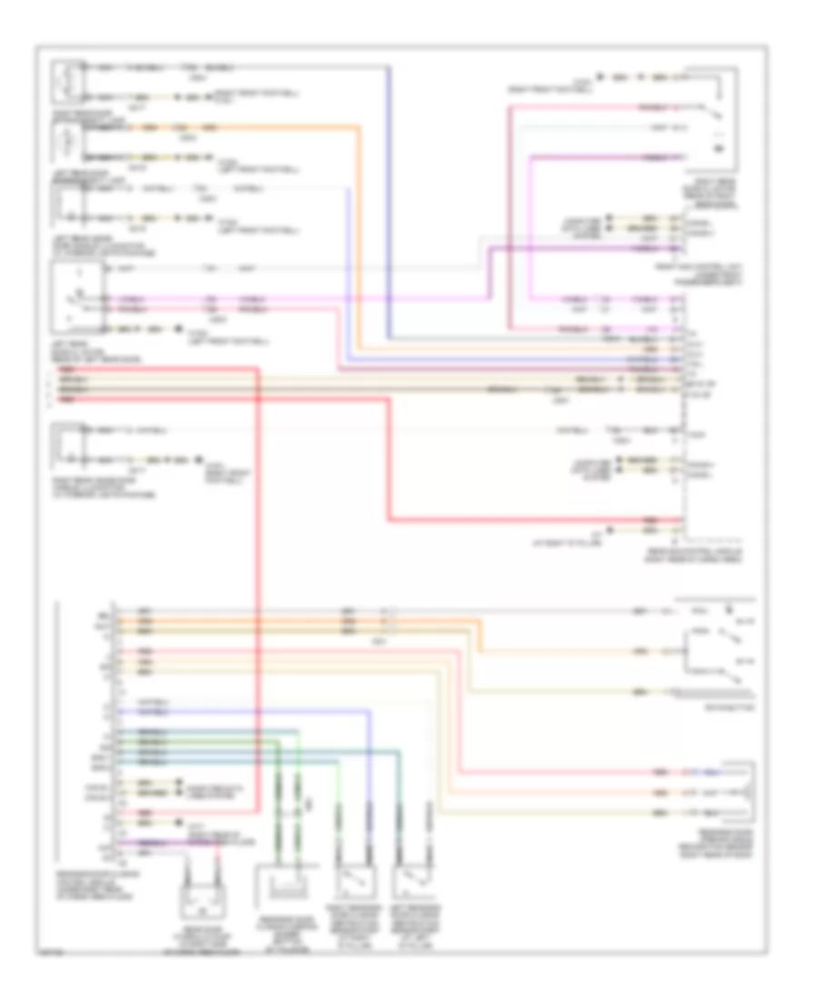 https://portal-diagnostov.com/license.html
Automotive Electricians Portal FZCO
Automotive Electricians Portal FZCO
https://portal-diagnostov.com/license.html
https://portal-diagnostov.com/license.html
Automotive Electricians Portal FZCO
Automotive Electricians Portal FZCOList of elements for Automatic Door Locks Wiring Diagram (2 of 2) for Mercedes-Benz GL350 2012:
- (right front footwell) w15/1
- Al(+)
- Auf
- Bel
- Bf zv df
- Can b h
- Can b l
- Can-b h
- Can-b l
- Computer data lines system
- Eks 1
- Eks 2
- F zv df
- Front sam control unit (under front passenger's seat)
- Left rear door cl motor (rear of left rear door)
- Left rear door entrance/exit lamp
- Left rear inside door handle illumination (w/ interior lights package)
- Left rear-end door closing obstruction sensor strip (at left "d" pillar)
- Nca
- Rear door hydraulic pump (in right side of cargo area floor)
- Rear sam control module (right rear of cargo area)
- Rear-end door closing control module (under right rear of cargo area floor)
- Rear-end door closing warning buzzer (bottom of tailgate)
- Rear-end door opening angle recognition sensor (right rear of roof)
- Red
- Right rear door cl motor (rear of right rear door)
- Right rear door entrance/exit lamp
- Right rear inside door handle illumination (w/ interior lights package)
- Right rear-end door closing obstruction sensor strip (at right "d" pillar)
- Rwt
- Rwts button
- Sig
- Tig l
- Tig r
- W15/1 (right front footwell)
- W15/2 (left front footwell)
- W7 (at right "d" pillar)
- W7/7 (right rear of cargo area floor)
- X35/1
- X35/3
- X35/4
- X8/16
- X8/17
- X8/4
Keyless Go System Wiring Diagram for Mercedes-Benz GL350 2012
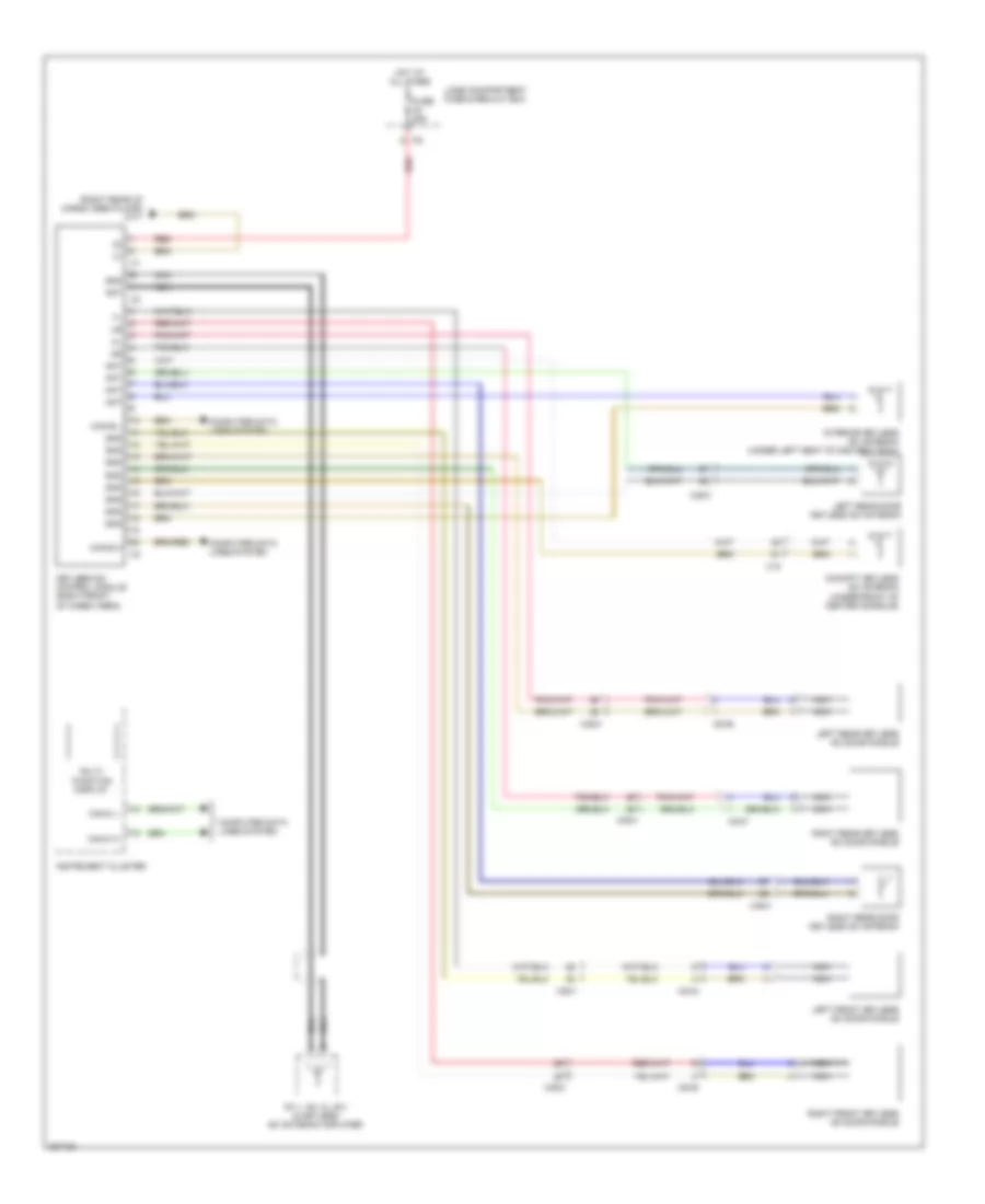 https://portal-diagnostov.com/license.html
Automotive Electricians Portal FZCO
Automotive Electricians Portal FZCO
https://portal-diagnostov.com/license.html
https://portal-diagnostov.com/license.html
Automotive Electricians Portal FZCO
Automotive Electricians Portal FZCOList of elements for Keyless Go System Wiring Diagram for Mercedes-Benz GL350 2012:
- (right rear of cargo area floor) w7/7
- Ant
- Can-b h
- Can-b l
- Can-c h
- Can-c l
- Cockpit keyless go antenna (under front of center console)
- Computer data lines system
- Fm 1, am, cl (zv) & keyless go antenna amplifier
- Fuse 25a
- Gnd
- Hot at all times
- Instrument cluster
- Interior keyless go antenna (under left seat of 2nd seat row)
- Keyless go control module (right front of cargo area)
- Left front keyless go door handle
- Left rear door keyless go antenna
- Left rear keyless go door handle
- Lode compartment fuse & realay box
- Multi- function display
- Nca
- Red
- Right front keyless go door handle
- Right rear door keyless go antenna
- Right rear keyless go door handle
- X18
- X35/1
- X35/2
- X35/3
- X35/4
- X8/34
- X8/35
- X8/36
- X8/37
POWER MIRRORS
Automatic Day/Night Mirror Wiring Diagram for Mercedes-Benz GL350 2012
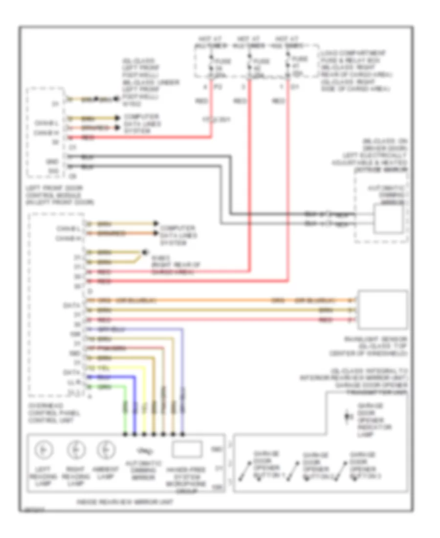 https://portal-diagnostov.com/license.html
Automotive Electricians Portal FZCO
Automotive Electricians Portal FZCO
https://portal-diagnostov.com/license.html
https://portal-diagnostov.com/license.html
Automotive Electricians Portal FZCO
Automotive Electricians Portal FZCOList of elements for Automatic Day/Night Mirror Wiring Diagram for Mercedes-Benz GL350 2012:
- (gl-class: integral to interior rearview mirror unit) garage door opener transmitter unit
- (gl-class: left front footwell) (ml-class: under left front footwell) w15/2
- (ml-class: on driver door) left electrically adjustable & heated outside mirror
- 15r
- 58d
- Ambient lamp
- Automatic dimming mirror
- Can-b h
- Can-b l
- Computer data lines system
- Data
- Fuse 25a
- Garage door opener button 1
- Garage door opener button 2
- Garage door opener button 3
- Garage door opener indicator lamp
- Gnd
- Hands-free system microphone group
- Hot at all times
- Inside rearview mirror unit
- Left front door control module (in left front door)
- Left reading lamp
- Ll l
- Ll r
- Load compartment fuse & relay box (ml-class: right rear of cargo area) (gl-class: right side of cargo area)
- Nca
- Overhead control panel control unit
- Rain/light sensor (gl-class: top center of windshield)
- Red
- Right reading lamp
- Sig
- W48/3 (right rear of cargo area)
- X35/1
Power Mirror Wiring Diagram for Mercedes-Benz GL350 2012
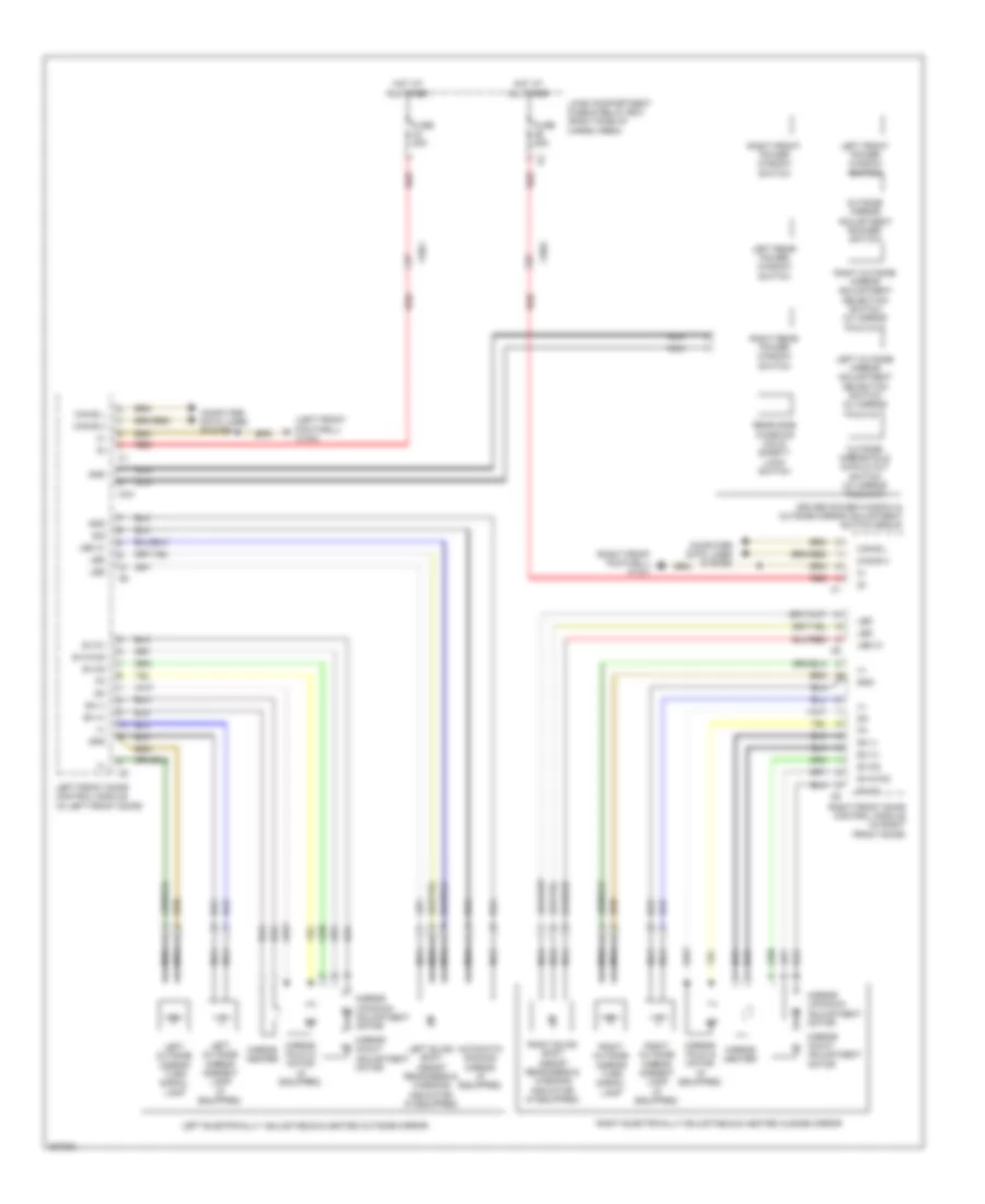 https://portal-diagnostov.com/license.html
Automotive Electricians Portal FZCO
Automotive Electricians Portal FZCO
https://portal-diagnostov.com/license.html
https://portal-diagnostov.com/license.html
Automotive Electricians Portal FZCO
Automotive Electricians Portal FZCOList of elements for Power Mirror Wiring Diagram for Mercedes-Benz GL350 2012:
- (+)
- (left front footwell) w15/2
- (right front footwell) w15/1
- Adjustment motor
- Automatic dimming mirror (if equipped)
- C3a
- Can-b h
- Can-b l
- Computer data lines system
- Driver power window & outside mirror adjustment switch group
- Fuse 25a
- Gnd
- Hot at all times
- Led
- Led 31
- Left blind spot assist readiness & warning indicator (if equipped)
- Left electrically adjustable & heated outside mirror
- Left front door control module (in left front door)
- Left front power window switch
- Left outside mirror adjustment selection switch (w/ mirror fold out)
- Left outside mirror ambient lamp (if equipped)
- Left outside mirror turn signal lamp
- Left rear power window switch
- Load compartment fuse & relay box (right side of cargo area)
- Mirror fold in motor (if equipped)
- Mirror heater
- Mirror in/out adjustment motor
- Mirror up/down adjustment motor
- Mirror up/down m
- Nca
- Outside mirror adjustment rocker switch
- Outside mirror fold in/fold out switch (w/ mirror fold out)
- Rear side windows child safety lock switch
- Red
- Right blind spot assist readiness & warning indicator (if equipped)
- Right electrically adjustable & heated ouside mirror
- Right front door control module (in right front door)
- Right front power window switch
- Right outside mirror adjustment selection switch (w/ mirror fold out)
- Right outside mirror ambient lamp (if equipped)
- Right outside mirror turn signal lamp
- Right rear power window switch
- Sh (+)
- Sh (-)
- Sig
- Sv-m1
- Sv-m1m2
- Sv-m2
- X35/1
- X35/2
POWER SEATS
Heated Steering Wheel Wiring Diagram for Mercedes-Benz GL350 2012
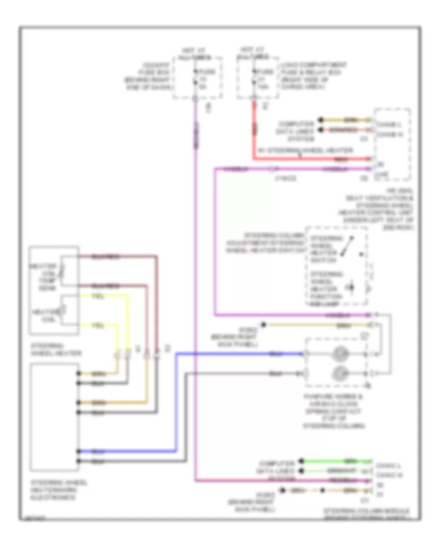 https://portal-diagnostov.com/license.html
Automotive Electricians Portal FZCO
Automotive Electricians Portal FZCO
https://portal-diagnostov.com/license.html
https://portal-diagnostov.com/license.html
Automotive Electricians Portal FZCO
Automotive Electricians Portal FZCOList of elements for Heated Steering Wheel Wiring Diagram for Mercedes-Benz GL350 2012:
- 13a
- Adjustment/steering wheel heater switch
- Can-b h
- Can-b l
- Can-c h
- Can-c l
- Cockpit fuse box (behind right end of dash)
- Coil
- Computer data lines system
- Fanfare horns & air bag clock spring contact (top of steering column)
- Fuse 10a
- Fuse 5a
- Heater
- Heater coil temp sens
- Hot at all times
- Hs (sih), seat ventilation & steering wheel heater control unit (under left seat of 2nd row)
- Lhz
- Load compartment fuse & relay box (right side of cargo area)
- Red
- Steering column module (behind steering wheel)
- Steering column steering wheel heater switch
- Steering wheel heater
- Steering wheel heater function ind lamp
- Steering wheel heater/horn electronics
- W/ steering wheel heater
- W29/2 (behind right kick panel)
- X18-c2
Lumbar Wiring Diagram for Mercedes-Benz GL350 2012
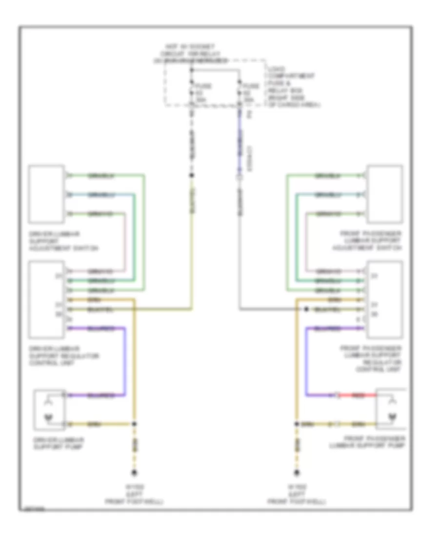 https://portal-diagnostov.com/license.html
Automotive Electricians Portal FZCO
Automotive Electricians Portal FZCO
https://portal-diagnostov.com/license.html
https://portal-diagnostov.com/license.html
Automotive Electricians Portal FZCO
Automotive Electricians Portal FZCOList of elements for Lumbar Wiring Diagram for Mercedes-Benz GL350 2012:
- Driver lumbar support adjustment switch
- Driver lumbar support pump
- Driver lumbar support regulator control unit
- Front passenger lumbar support adjustment switch
- Front passenger lumbar support pump
- Front passenger lumbar support regulator control unit
- Fuse 30a
- Hot w/ socket circuit 15r relay (w/ run-on) energized
- Load compartment fuse & relay box (right side of cargo area)
- Red
- W15/2 (left front footwell)
- X55/4-c1
Power Seat Wiring Diagram for Mercedes-Benz GL350 2012
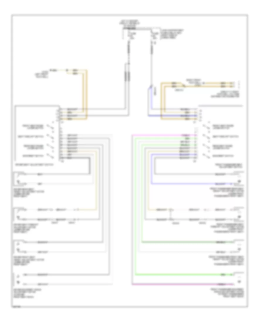 https://portal-diagnostov.com/license.html
Automotive Electricians Portal FZCO
Automotive Electricians Portal FZCO
https://portal-diagnostov.com/license.html
https://portal-diagnostov.com/license.html
Automotive Electricians Portal FZCO
Automotive Electricians Portal FZCOList of elements for Power Seat Wiring Diagram for Mercedes-Benz GL350 2012:
- (right front footwell) w15/1
- Backrest switch
- Circuit 31 right footwell voltage distributor connector
- Driver backrest angle adjustment motor (in driver front seat back)
- Driver front seat height adjustment motor (under driver front seat)
- Driver rear seat height adjustment motor (under driver front seat)
- Driver seat adjustment switch
- Driver seat fore/aft adjustment motor (under driver front seat)
- Front passenger backrest angle adjustment motor (in front passenger's front seat back)
- Front passenger front seat height adjustment motor (under front passenger's front seat)
- Front passenger rear seat height adjustment motor (under front passenger's front seat)
- Front passenger seat adjustment switch
- Front passenger seat fore/aft adjustment motor (under front passenger's front seat)
- Front seat raise/ lower switch
- Fuse 30a
- Hot w/ socket circuit 15r relay (w/ run-on) energized
- Load compartment fuse & relay box (right side of cargo area)
- Rear seat raise/ lower switch
- Seat forc/aft switch
- W15/2 (left front footwell)
- X54/31
- X54/32
- X55/4-c1
Rear Folding Seat Wiring Diagram for Mercedes-Benz GL350 2012
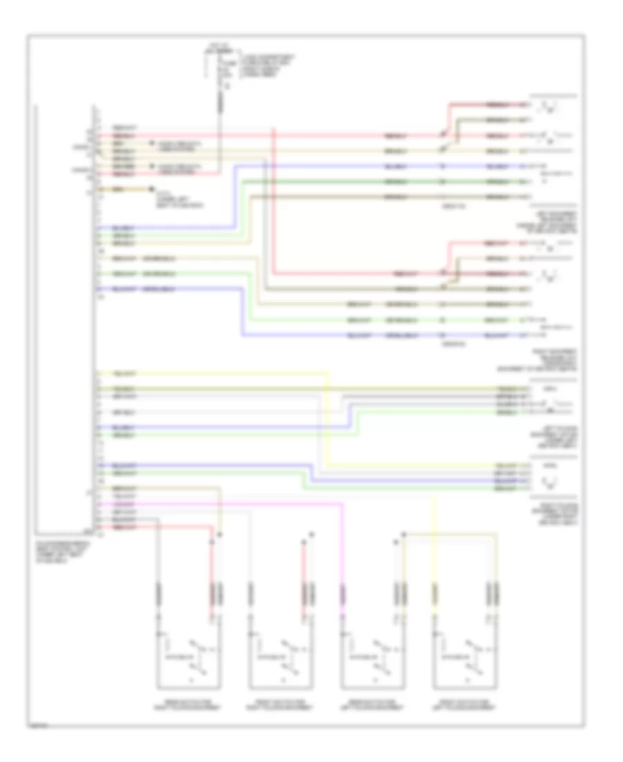 https://portal-diagnostov.com/license.html
Automotive Electricians Portal FZCO
Automotive Electricians Portal FZCO
https://portal-diagnostov.com/license.html
https://portal-diagnostov.com/license.html
Automotive Electricians Portal FZCO
Automotive Electricians Portal FZCOList of elements for Rear Folding Seat Wiring Diagram for Mercedes-Benz GL350 2012:
- +5v
- Can-b h
- Can-b l
- Computer data lines system
- Folding rear bench seat control unit (under left seat of 2nd row)
- Front switch for left folding backrest
- Front switch for right folding backrest
- Fuse 40a
- Hot at all times
- Left backrest release unit (inside left backrest of 3rd row seats)
- Left folding backrest motor (under left 3rd row seat)
- Load compartment fuse & relay box (right side of cargo area)
- Rear switch for left folding backrest
- Rear switch for right folding backrest
- Right backrest release unit (inside right backrest of 3rd row seats)
- Right folding backrest motor (under right 3rd row seat)
- W17/1 (under left seat of 2nd row)
- X55/21-c2
- X55/22-c2
Seat Ventilation Wiring Diagram (1 of 2) for Mercedes-Benz GL350 2012
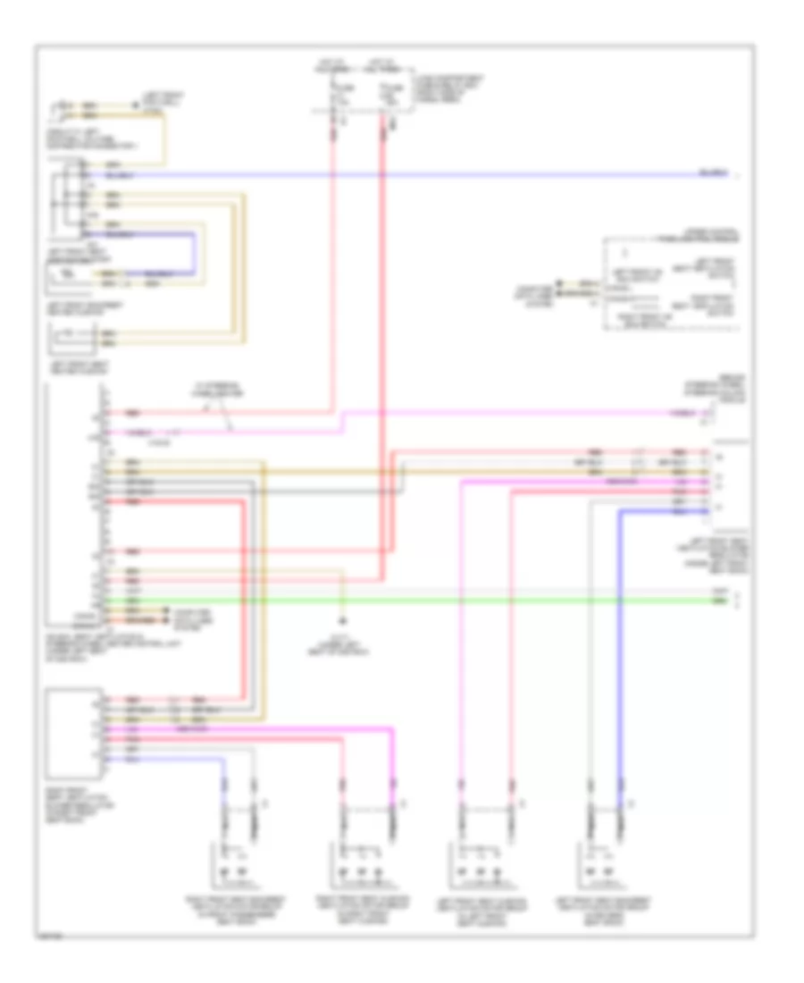 https://portal-diagnostov.com/license.html
Automotive Electricians Portal FZCO
Automotive Electricians Portal FZCO
https://portal-diagnostov.com/license.html
https://portal-diagnostov.com/license.html
Automotive Electricians Portal FZCO
Automotive Electricians Portal FZCOList of elements for Seat Ventilation Wiring Diagram (1 of 2) for Mercedes-Benz GL350 2012:
- (behind steering wheel) steering column module
- (left front footwell) w15/2
- 4a1
- 4a2
- Can-b h
- Can-b l
- Circuit 31 left footwell voltage distributor connector 1
- Computer data lines system
- Fuse 10a
- Fuse 25a
- Hot at all times
- Hs (sih), seat ventilation & steering wheel heater control unit (under left seat of 2nd row)
- Left front backrest heated cushion
- Left front hs (sih) switch
- Left front seat backrest ventilation motor group (in driver's seat back)
- Left front seat contacting strip
- Left front seat cushion ventilation motor group (in left front seat cushion)
- Left front seat heated cushion
- Left front seat ventilation blower regulator (inside left front seat back)
- Left front seat ventilation switch
- Lhz
- Load compartment fuse & relay box (right side of cargo area)
- Ms3
- Nca
- Pnk
- Red
- Right front hs (sih) switch
- Right front seat backrest ventilation motor group (in front passenger's seat back)
- Right front seat cushion ventilation motor group (in right front seat cushion)
- Right front seat ventilation blower regulator (in right front seat back)
- Right front seat ventilation switch
- Sig
- Upper control panel control module
- W/ steering wheel heater
- W17/1 (under left seat of 2nd row)
- X18-c2
- X55/3-c4c
- X55/4-c4c
Seat Ventilation Wiring Diagram (2 of 2) for Mercedes-Benz GL350 2012
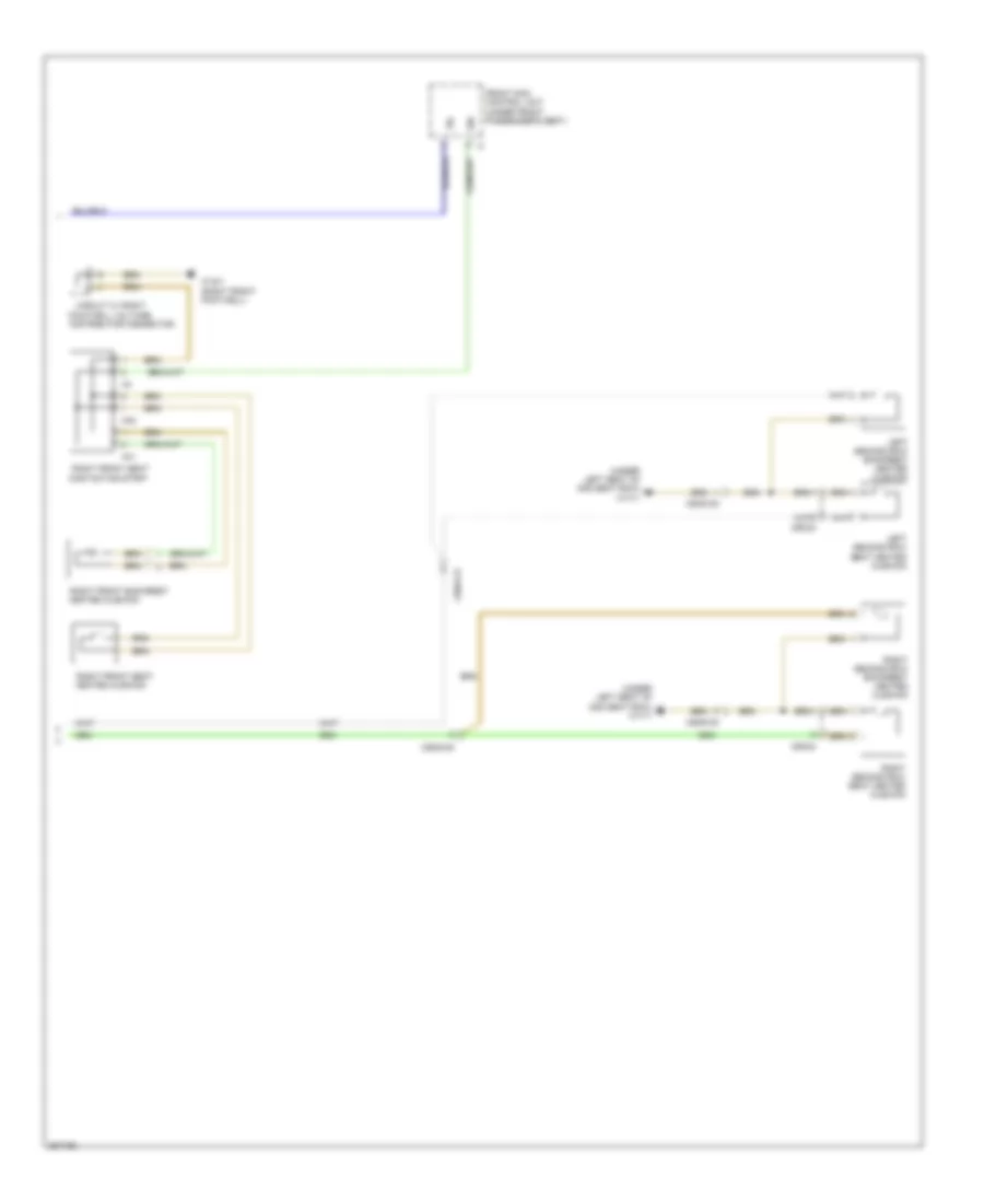 https://portal-diagnostov.com/license.html
Automotive Electricians Portal FZCO
Automotive Electricians Portal FZCO
https://portal-diagnostov.com/license.html
https://portal-diagnostov.com/license.html
Automotive Electricians Portal FZCO
Automotive Electricians Portal FZCOList of elements for Seat Ventilation Wiring Diagram (2 of 2) for Mercedes-Benz GL350 2012:
- (under left seat of 2nd seat row) w17/1
- 4a1
- 4a2
- Circuit 31 right
- Distributor connector
- Footwell voltage
- Front sam control unit (under front passenger's seat)
- Heated cushion
- Left second row backrest heated cushion
- Left second row seat heated cushion
- Right front backrest
- Right front seat
- Right front seat contacting strip
- Right second row backrest heated cushion
- Right second row seat heated cushion
- Sil
- Sir
- W15/1 (right front footwell)
- X55/23
- X55/24
- X55/5-c5
- X55/6-c5
POWER TOP/SUNROOF
Power Top/Sunroof Wiring Diagram for Mercedes-Benz GL350 2012
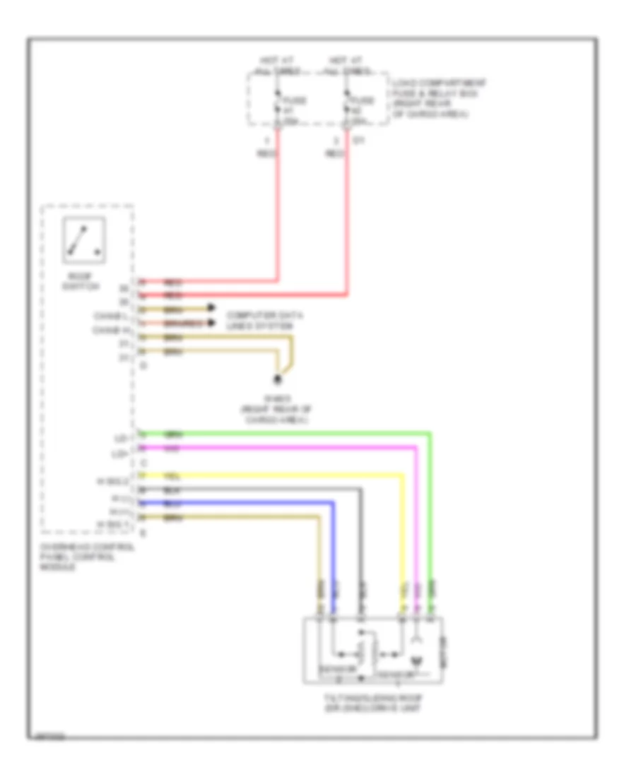 https://portal-diagnostov.com/license.html
Automotive Electricians Portal FZCO
Automotive Electricians Portal FZCO
https://portal-diagnostov.com/license.html
https://portal-diagnostov.com/license.html
Automotive Electricians Portal FZCO
Automotive Electricians Portal FZCOList of elements for Power Top/Sunroof Wiring Diagram for Mercedes-Benz GL350 2012:
- Can-b h
- Can-b l
- Computer data lines system
- Fuse 25a
- H (+)
- H (-)
- H sig 1
- H sig 2
- Hot at all times
- Ld+
- Ld-
- Load compartment fuse & relay box (right rear of cargo area)
- Motor
- Overhead control panel control module
- Red
- Roof switch
- Sensor
- Tilting/sliding roof (sr (shd)) drive unit
- W48/3 (right rear of cargo area)
POWER WINDOWS
Power Windows Wiring Diagram (1 of 2) for Mercedes-Benz GL350 2012
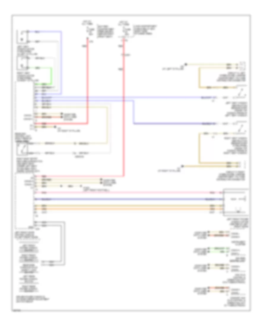 https://portal-diagnostov.com/license.html
Automotive Electricians Portal FZCO
Automotive Electricians Portal FZCO
https://portal-diagnostov.com/license.html
https://portal-diagnostov.com/license.html
Automotive Electricians Portal FZCO
Automotive Electricians Portal FZCOList of elements for Power Windows Wiring Diagram (1 of 2) for Mercedes-Benz GL350 2012:
- Aac (kla) control & operating unit (w/o thermotronic)
- Battery compartment prefuse box (behind right front seat)
- C3a
- C79
- Can b h
- Can b l
- Can-b h
- Can-b l
- Can-c h
- Can-c l
- Circuit 31 left wheelhouse luggage compartment voltage distributor connector
- Circuit 31 right wheelhouse luggage compartment voltage distributor connector
- Comfort aac (kla) control & operating unit (w/ thermotronic)
- Computer data lines system
- Driver power window & outside mirror adjustment switch group
- Eis (ezs) control unit
- Fuse 25a
- Fuse 60a
- Gnd
- Hot at all times
- Instrument cluster
- Left front door control module (in left front door)
- Left front power window motor (center of left front door)
- Left front power window switch
- Left rear power window switch
- Left vent window motor (if equipped) (in left "d" pillar)
- Left vent window obstruction sensor strip (inside top window frame of left vent window)
- Load compartment fuse & relay box (right side of cargo area)
- Nca
- Pnk
- Rear sam control unit (right rear of cargo area)
- Rear side windows child safety lock switch
- Red
- Right easy entry feature microswitch (2nd seat row) (under left seat of 2nd seat row, inside locking unit)
- Right front power window switch
- Right rear power window switch
- Right vent window motor (if equipped) (in right "d" pillar)
- Right vent window obstruction sensor strip (if equipped) (inside top window frame of right vent window)
- W15/2 (left front footwell)
- W6 (at left "d" pillar)
- W7 (at right "d" pillar)
- X35/1
- X55/6-c5
Power Windows Wiring Diagram (2 of 2) for Mercedes-Benz GL350 2012
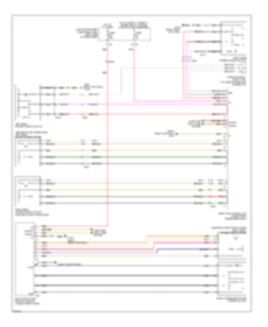 https://portal-diagnostov.com/license.html
Automotive Electricians Portal FZCO
Automotive Electricians Portal FZCO
https://portal-diagnostov.com/license.html
https://portal-diagnostov.com/license.html
Automotive Electricians Portal FZCO
Automotive Electricians Portal FZCOList of elements for Power Windows Wiring Diagram (2 of 2) for Mercedes-Benz GL350 2012:
- (center of left rear door) left rear power window motor
- (center of right front door) right front power window motor
- (left front footwell) w15/2
- (right front footwell) w15/1
- 58d
- C3a
- Can-b h
- Can-b l
- Computer data lines system
- Door locks system
- Front passenger power window switch
- Front sam control unit (under front passenger's seat)
- Fuse 25a
- Fuse 5a
- Gnd
- Hot at all times
- Hot w/ circuit 15 relay/ spare1 relay (change over contact) energized
- Ki 58
- Left rear power window switch
- Load compartment fuse & relay box (right side of cargo area)
- Nca
- Pnk
- Power window switch
- Red
- Right front door control module (in right front door)
- Right rear
- Right rear power window motor (center of right rear door)
- W15/1 (right front footwell)
- Wake-up signal/ circuit 58d voltage distributor connector
- X35/2
- X35/3
- X35/4
- X8/16
- X8/17
RADIO
COMAND Actuation Wiring Diagram (1 of 2) for Mercedes-Benz GL350 2012
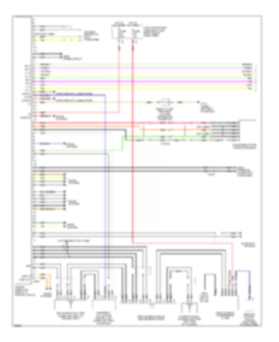 https://portal-diagnostov.com/license.html
Automotive Electricians Portal FZCO
Automotive Electricians Portal FZCO
https://portal-diagnostov.com/license.html
https://portal-diagnostov.com/license.html
Automotive Electricians Portal FZCO
Automotive Electricians Portal FZCOList of elements for COMAND Actuation Wiring Diagram (1 of 2) for Mercedes-Benz GL350 2012:
- (not used)
- (pin 5-8 not used)
- Can-b h
- Can-b l
- Circuit 31 left rear seat voltage distributor connector
- Comand operating, display & control module
- Computer data lines system
- Emergency call system control unit (under left seat of 2nd row)
- Fm rear window antenna amplifier (left side of tailgate)
- Fuse 20a
- Fuse 5a
- Gps
- Gps antenna splitter (under left seat of 2nd seat row)
- Hands-free system microphone group
- Hl (+)
- Hl (-)
- Hot at all times
- Hr (+)
- Hr (-)
- Interface connector 2 (if equipped)
- Load compartment fuse & relay box (right side of cargo area)
- Media
- Most
- Most in
- Most out
- Mute
- Nca
- Pnk
- Radio antenna interference filter
- Rear camera circuit
- Rear sam control module (right rear of cargo area)
- Red
- Roof antenna module (center rear of roof)
- Sound systems
- Vl (+)
- Vl (-)
- Vr (+)
- Vr (-)
- W/o high-definition tuner
- W17/1 (under left seat of 2nd row)
- W29/8 (top of left "d" pillar)
- Wake up
- Walkman separation point (if equipped)
- X18/2-c3
- X18/67
COMAND Actuation Wiring Diagram (2 of 2) for Mercedes-Benz GL350 2012
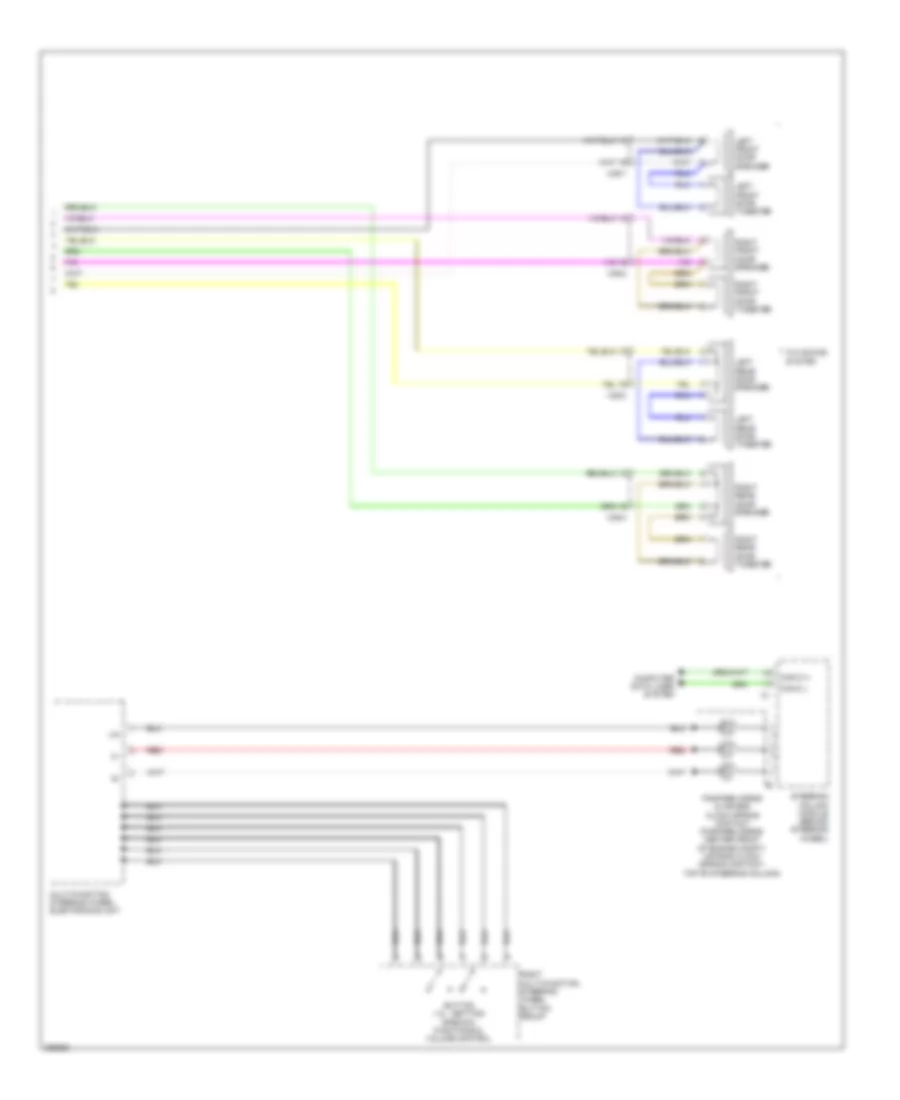 https://portal-diagnostov.com/license.html
Automotive Electricians Portal FZCO
Automotive Electricians Portal FZCO
https://portal-diagnostov.com/license.html
https://portal-diagnostov.com/license.html
Automotive Electricians Portal FZCO
Automotive Electricians Portal FZCOList of elements for COMAND Actuation Wiring Diagram (2 of 2) for Mercedes-Benz GL350 2012:
- Button + & -, setting specific functions & volume control
- Can-c h
- Can-c l
- Computer data lines system
- Fanfare horns & air bag clock spring contact (fanfare horns: center front of engine compt) (air bag clock spring contact: top of steering column)
- Left front door speaker
- Left front door tweeter
- Left rear door speaker
- Left rear door tweeter
- Lin
- Multi-function steering wheel electronics unit
- Red
- Right front door speaker
- Right front door tweeter
- Right multi-function steering wheel button group
- Right rear door speaker
- Right rear door tweeter
- Steering column module (behind steering wheel)
- W/o sound system
- X35/1
- X35/2
- X35/3
- X35/4
DVD Player Wiring Diagram for Mercedes-Benz GL350 2012
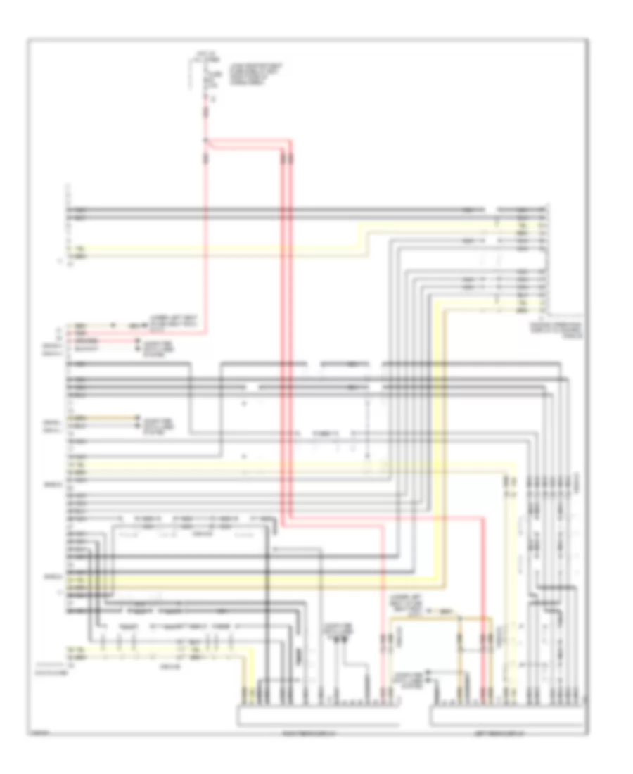 https://portal-diagnostov.com/license.html
Automotive Electricians Portal FZCO
Automotive Electricians Portal FZCO
https://portal-diagnostov.com/license.html
https://portal-diagnostov.com/license.html
Automotive Electricians Portal FZCO
Automotive Electricians Portal FZCOList of elements for DVD Player Wiring Diagram for Mercedes-Benz GL350 2012:
- (-)
- (under left seat of 2nd seat row) w17/1
- Can-a h
- Can-a l
- Can-b h
- Can-b l
- Comand operating, display & control module
- Computer data lines system
- Dvd player
- Fuse 10a
- Hot at all times
- Left rear display
- Load compartment fuse & relay box (right side of cargo area)
- Nca
- Red
- Right rear display
- Shield
- X55/3-c5
- X55/3-c6
- X55/4-c5
- X55/4-c6
High Definition Tuner Wiring Diagram for Mercedes-Benz GL350 2012
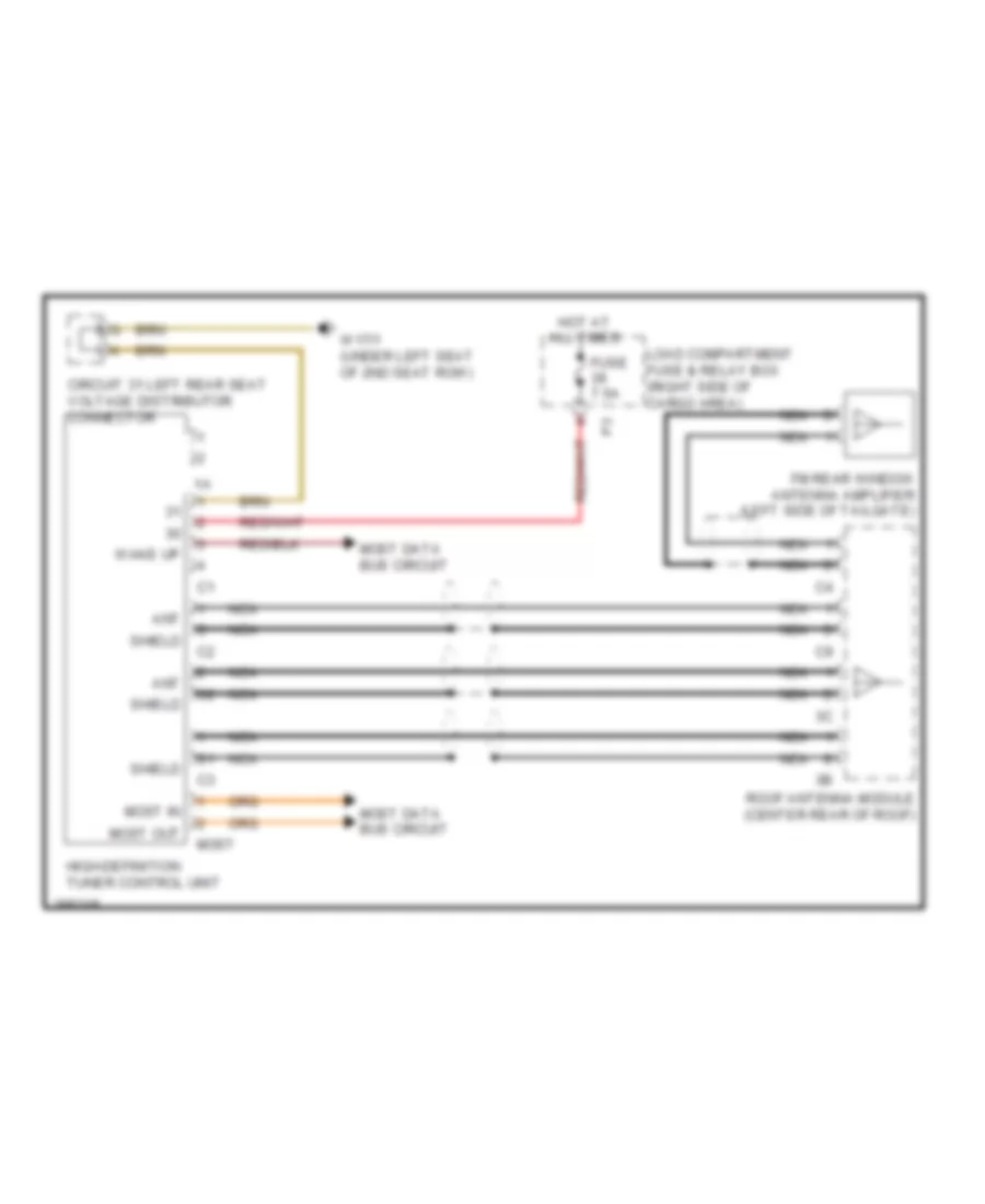 https://portal-diagnostov.com/license.html
Automotive Electricians Portal FZCO
Automotive Electricians Portal FZCO
https://portal-diagnostov.com/license.html
https://portal-diagnostov.com/license.html
Automotive Electricians Portal FZCO
Automotive Electricians Portal FZCOList of elements for High Definition Tuner Wiring Diagram for Mercedes-Benz GL350 2012:
- Ant
- Circuit 31 left rear seat voltage distributor connector
- Fm rear window antenna amplifier (left side of tailgate)
- Fuse 7.5a
- High-definition tuner control unit
- Hot at all times
- Load compartment fuse & relay box (right side of cargo area)
- Most
- Most data bus circuit
- Most in
- Most out
- Nca
- Roof antenna module (center rear of roof)
- Shield
- W17/1 (under left seat of 2nd seat row)
- Wake up
MOST Data Bus Wiring Diagram for Mercedes-Benz GL350 2012
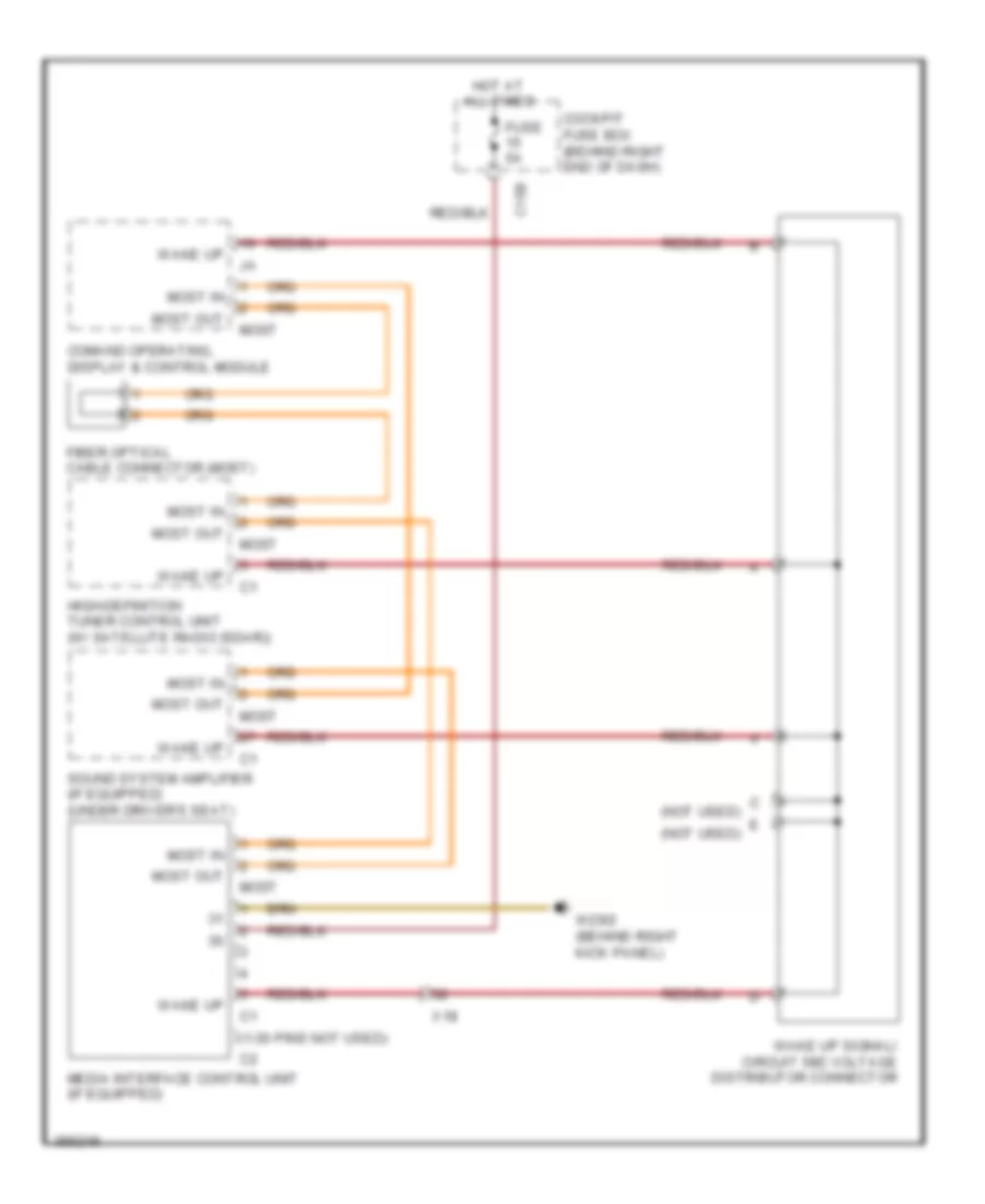 https://portal-diagnostov.com/license.html
Automotive Electricians Portal FZCO
Automotive Electricians Portal FZCO
https://portal-diagnostov.com/license.html
https://portal-diagnostov.com/license.html
Automotive Electricians Portal FZCO
Automotive Electricians Portal FZCOList of elements for MOST Data Bus Wiring Diagram for Mercedes-Benz GL350 2012:
- (1-30 pins not used)
- (not used)
- C15b
- Cockpit fuse box (behind right end of dash)
- Comand operating, display & control module
- Fiber optical cable connector (most)
- Fuse 5a
- High-definition tuner control unit (w/ satellite radio (sdar))
- Hot at all times
- Media interface control unit (if equipped)
- Most
- Most in
- Most out
- Sound system amplifier (if equipped) (under driver's seat)
- W29/2 (behind right kick panel)
- Wake up
- Wake up signal/ circuit 58d voltage distributor connector
- X18
Rear Audio Wiring Diagram for Mercedes-Benz GL350 2012
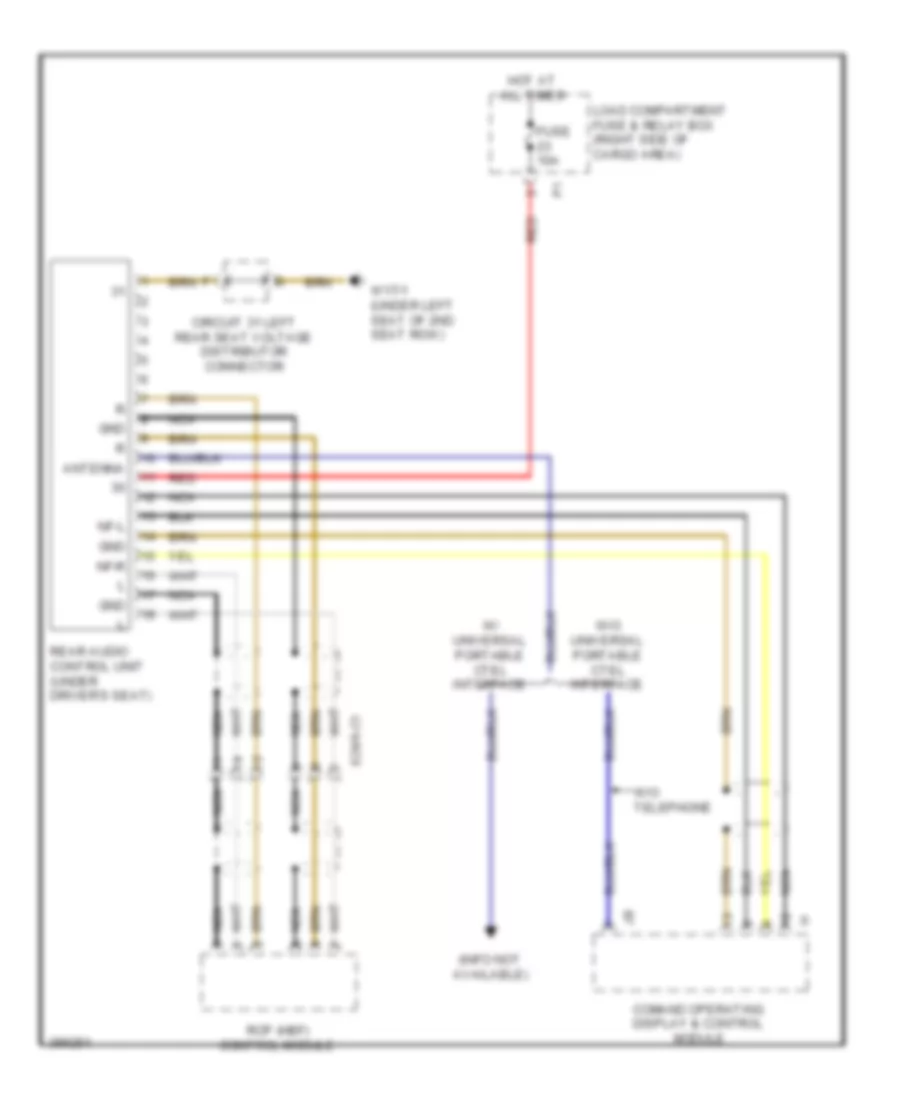 https://portal-diagnostov.com/license.html
Automotive Electricians Portal FZCO
Automotive Electricians Portal FZCO
https://portal-diagnostov.com/license.html
https://portal-diagnostov.com/license.html
Automotive Electricians Portal FZCO
Automotive Electricians Portal FZCOList of elements for Rear Audio Wiring Diagram for Mercedes-Benz GL350 2012:
- (info not available)
- Antenna
- Circuit 31 left rear seat voltage distributor connector
- Comand operating display & control module
- Fuse 10a
- Gnd
- Hot at all times
- Load compartment fuse & relay box (right side of cargo area)
- Nca
- Nf-l
- Nf-r
- Rcp (hbf) control module
- Rear audio control unit (under driver's seat)
- Red
- W/ universal portable ctel interface
- W/o telephone
- W/o universal portable ctel interface
- W17/1 (under left seat of 2nd seat row)
- X29/6-c1
Sound Amplifier Wiring Diagram for Mercedes-Benz GL350 2012
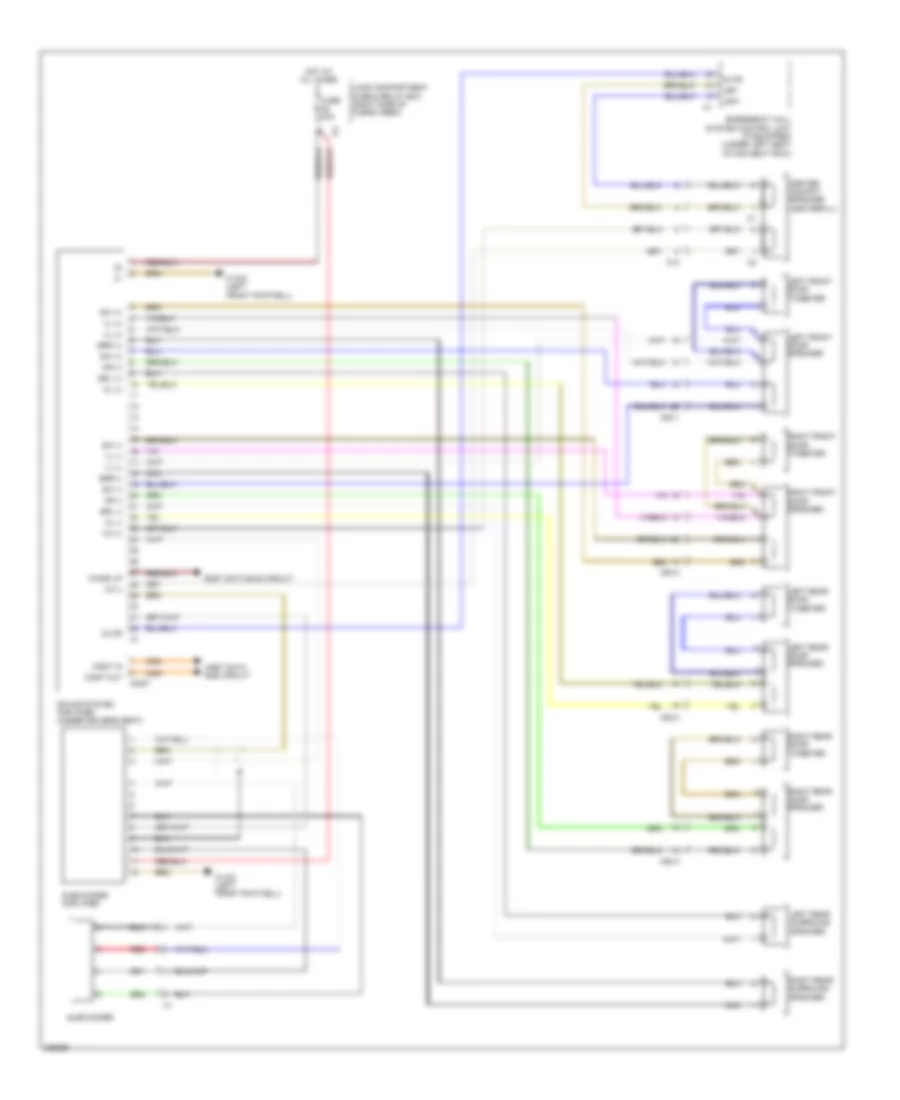 https://portal-diagnostov.com/license.html
Automotive Electricians Portal FZCO
Automotive Electricians Portal FZCO
https://portal-diagnostov.com/license.html
https://portal-diagnostov.com/license.html
Automotive Electricians Portal FZCO
Automotive Electricians Portal FZCOList of elements for Sound Amplifier Wiring Diagram for Mercedes-Benz GL350 2012:
- Center cockpit speaker (centerfill)
- Emergency call system control unit (if equipped) (under left seat of 2nd seat row)
- Fuse 30a
- Hl (+)
- Hl (-)
- Hot at all times
- Hr (+)
- Hr (-)
- Left front door speaker
- Left front door tweeter
- Left rear door speaker
- Left rear door tweeter
- Left rear surround speaker
- Load compartment fuse & relay box (right side of cargo area)
- Lsp+
- Lsp-
- Most
- Most data bus circuit
- Most in
- Most out
- Mute
- Nca
- Red
- Right front door speaker
- Right front door tweeter
- Right rear door speaker
- Right rear door tweeter
- Right rear surround speaker
- Sound system amplifier (under driver's seat)
- Srl (+)
- Srl (-)
- Srr (+)
- Srr (-)
- Subwoofer
- Subwoofer amplifier
- Sw (+)
- Sw (-)
- Vl (+)
- Vl (-)
- Vm (+)
- Vm (-)
- W15/2 (left front footwell)
- Wake up
- X18
- X35/1
- X35/2
- X35/3
- X35/4
STARTING/CHARGING
Charging Wiring Diagram for Mercedes-Benz GL350 2012
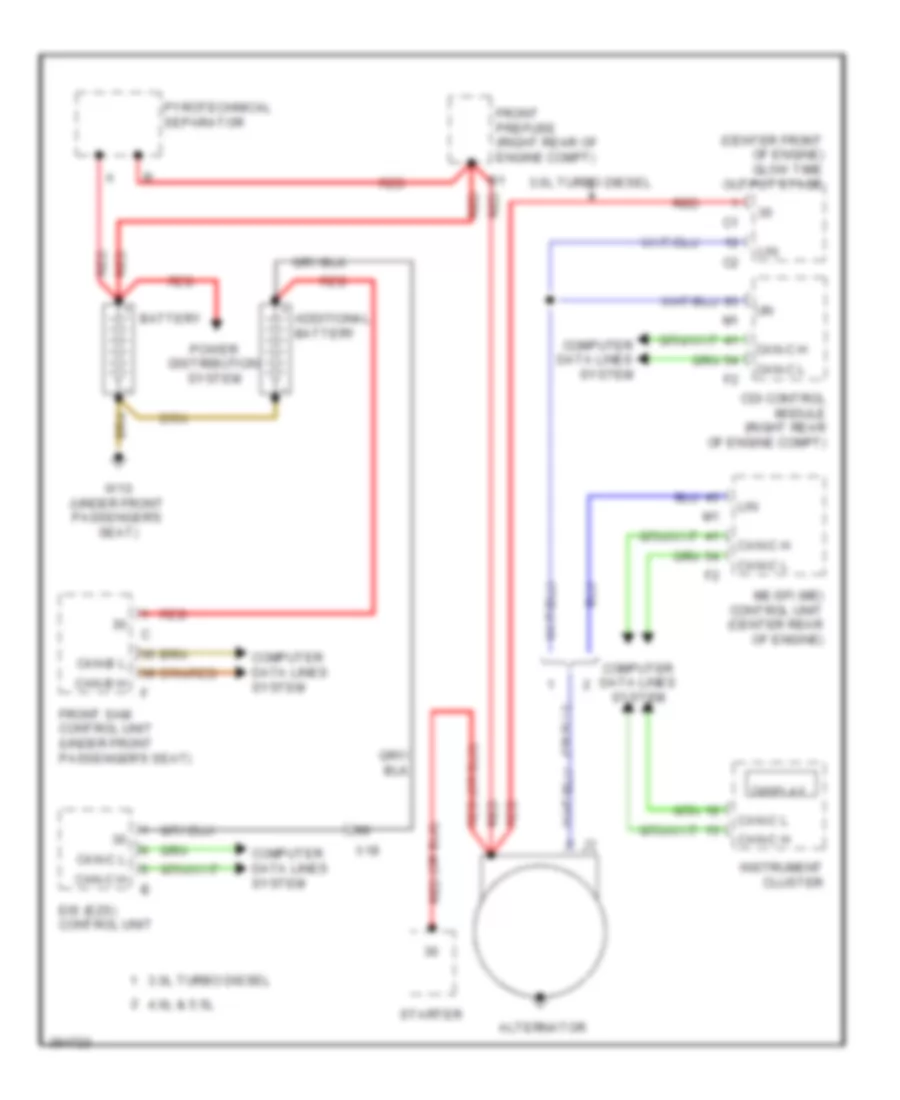 https://portal-diagnostov.com/license.html
Automotive Electricians Portal FZCO
Automotive Electricians Portal FZCO
https://portal-diagnostov.com/license.html
https://portal-diagnostov.com/license.html
Automotive Electricians Portal FZCO
Automotive Electricians Portal FZCOList of elements for Charging Wiring Diagram for Mercedes-Benz GL350 2012:
- (center front of engine) glow time output stage
- 3.0l turbo diesel
- 4.6l & 5.5l
- Additional battery
- Alternator
- Battery
- Can-b h
- Can-b l
- Can-c h
- Can-c l
- Cdi control module (right rear of engine compt)
- Computer data lines system
- Display
- Eis (ezs) control unit
- Front prefuse (right rear of engine compt)
- Front sam control unit (under front passenger's seat)
- Instrument cluster
- Lin
- Me-sfi (me) control unit (center rear of engine)
- Power distribution system
- Pyrotechnical separator
- Red
- Starter
- W10 (under front passenger's seat)
- X18
Starting Wiring Diagram for Mercedes-Benz GL350 2012
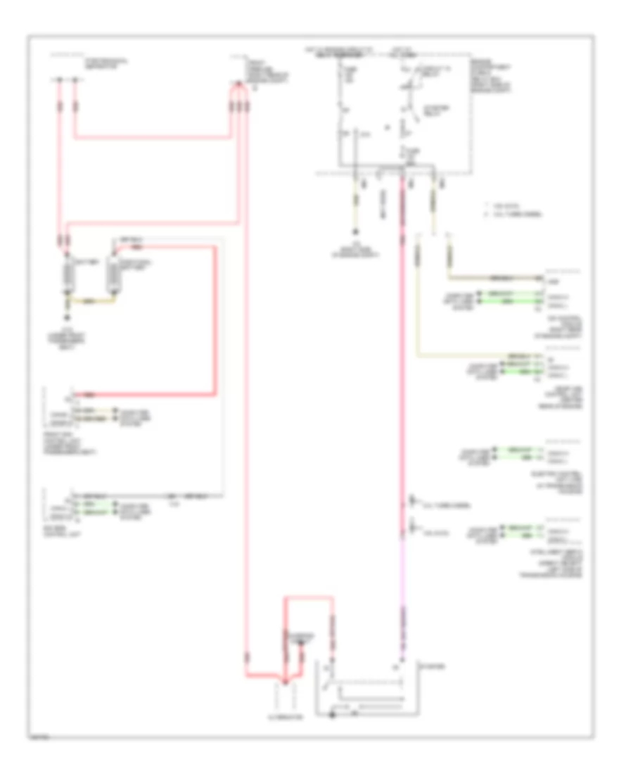 https://portal-diagnostov.com/license.html
Automotive Electricians Portal FZCO
Automotive Electricians Portal FZCO
https://portal-diagnostov.com/license.html
https://portal-diagnostov.com/license.html
Automotive Electricians Portal FZCO
Automotive Electricians Portal FZCOList of elements for Starting Wiring Diagram for Mercedes-Benz GL350 2012:
- (not used)
- 3.0l turbo diesel
- 4.6l & 5.5l
- 87a
- Additional battery
- Alternator
- Anr
- Battery
- Can-b h
- Can-b l
- Can-c h
- Can-c l
- Cdi control module (right rear of engine compt)
- Charging circuit
- Circuit 15 relay
- Computer data lines system
- Eis (ezs) control unit
- Electric control unit (vgs) (in transmission housing)
- Engine compartment fuse & relay box (right side of engine compt)
- Front prefuse (right rear of engine compt)
- Front sam control unit (under front passenger's seat)
- Fuse 15a
- Fuse 25a
- Hot at all times
- Hot w/ engine circuit 87 relay energized
- Intelligent servo module (direct select) (left side of transmission housing)
- Me-sfi (me) control unit (center rear of engine)
- Mr1
- Mr3
- Mr4
- Pnk
- Pyrotechnical separator
- Red
- Starter
- Starter relay
- W10 (under front passenger's seat)
- W2 (right side of engine compt)
- X18
- X18/7
- X26-c1
SUPPLEMENTAL RESTRAINTS
Emergency Seat Belt Tensioners Wiring Diagram for Mercedes-Benz GL350 2012
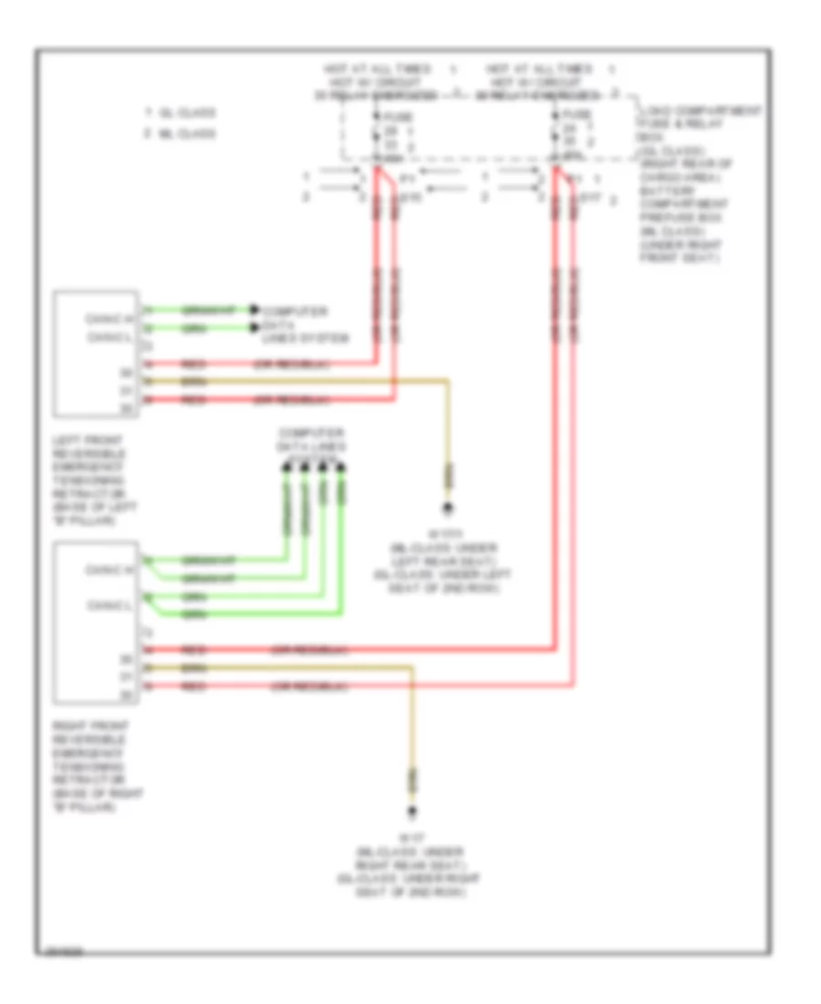 https://portal-diagnostov.com/license.html
Automotive Electricians Portal FZCO
Automotive Electricians Portal FZCO
https://portal-diagnostov.com/license.html
https://portal-diagnostov.com/license.html
Automotive Electricians Portal FZCO
Automotive Electricians Portal FZCOList of elements for Emergency Seat Belt Tensioners Wiring Diagram for Mercedes-Benz GL350 2012:
- Can-c h
- Can-c l
- Computer data lines system
- Fuse 40a
- Gl class
- Hot at all times hot w/ circuit 30 relay energized
- Left front reversible emergency tensioning retractor (base of left "b" pillar)
- Load compartment fuse & relay box (gl class) (right rear of cargo area) battery compartment prefuse box (ml class) (under right front seat)
- Ml class
- Red
- Right front reversible emergency tensioning retractor (base of right "b" pillar)
- S15 red
- S17 red
- W17 (ml-class: under right rear seat) (gl-class: under right seat of 2nd row)
- W17/1 (ml-class: under left rear seat) (gl-class: under left seat of 2nd row)
Supplemental Restraint Wiring Diagram (1 of 3) for Mercedes-Benz GL350 2012
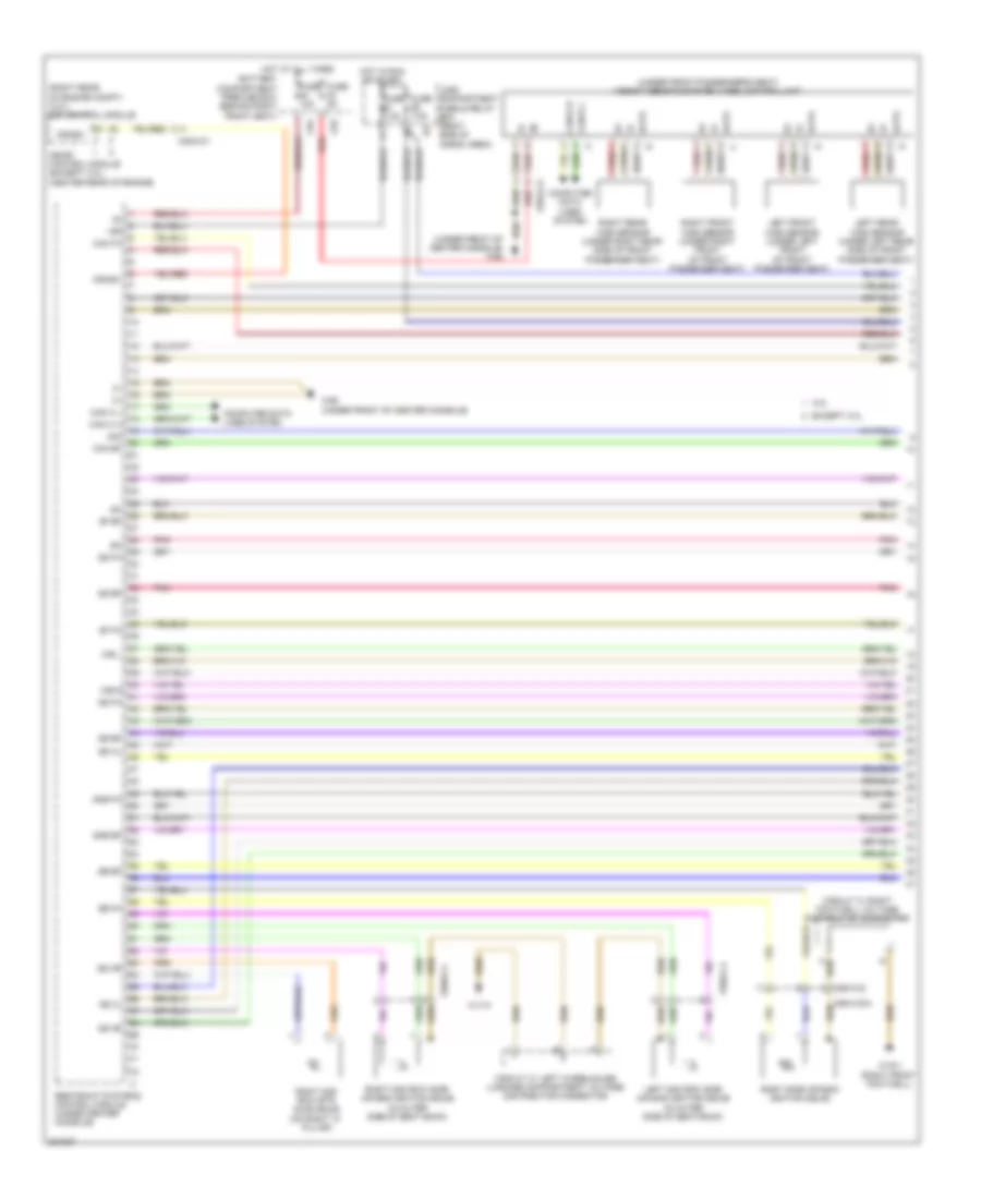 https://portal-diagnostov.com/license.html
Automotive Electricians Portal FZCO
Automotive Electricians Portal FZCO
https://portal-diagnostov.com/license.html
https://portal-diagnostov.com/license.html
Automotive Electricians Portal FZCO
Automotive Electricians Portal FZCOList of elements for Supplemental Restraint Wiring Diagram (1 of 3) for Mercedes-Benz GL350 2012:
- (right rear of engine compt) (3.0l) cdi control module
- (under front of center console) w26
- (under front passenger's seat) weight sensing system (wss) control unit
- 15r
- 3.0l
- Battery compartment prefuse box (behind right front seat)
- C83
- C84
- Cak bf
- Cak fa
- Can c h
- Can c l
- Can-b h
- Can-b l
- Circuit 31 left wheelhouse luggage compartment voltage distributor connector
- Circuit 31 right footwell voltage distributor connector
- Computer data lines system
- Crash
- Data
- Except 3.0l
- Fuse 10a
- Fuse 5a
- Fuse 7.5a
- Gkb bf
- Gkb fa
- Gs 3l
- Gs 3r
- Gs bf
- Gs fa
- Gs hl
- Gs hr
- Hot at all times
- Hot in run or start
- Left 2nd row side air bag ignition squib (in outer side of seat back)
- Left front wss sensor (under left front of front passenger seat)
- Left rear wss sensor (under left rear side of front passenger seat)
- Load compartment fuse & relay box (right side of cargo area)
- Me-sfi control module (except 3.0l) (center rear of engine)
- Pnk
- Red
- Restraint systems control module (under center console)
- Right 2nd row etr (gus) squib (on right "c" pillar)
- Right 2nd row side air bag ignition squib (in outer side of seat back)
- Right front wss sensor (under right front of front passenger seat)
- Right rear wss sensor (under right rear side of front passenger seat)
- Right side air bag ignition squib
- Sb bf
- Sb fa
- Sf bf
- Sf fa
- Sig
- Ss bf
- Ss fa
- W15/1 (right front footwell)
- W17/3
- W26 (under front of center console)
- Wb l
- Wb r
- X25/2-c1
- X55/4-c2
- X55/4-c2a
- X55/5-c4
- X55/6-c4
Supplemental Restraint Wiring Diagram (2 of 3) for Mercedes-Benz GL350 2012
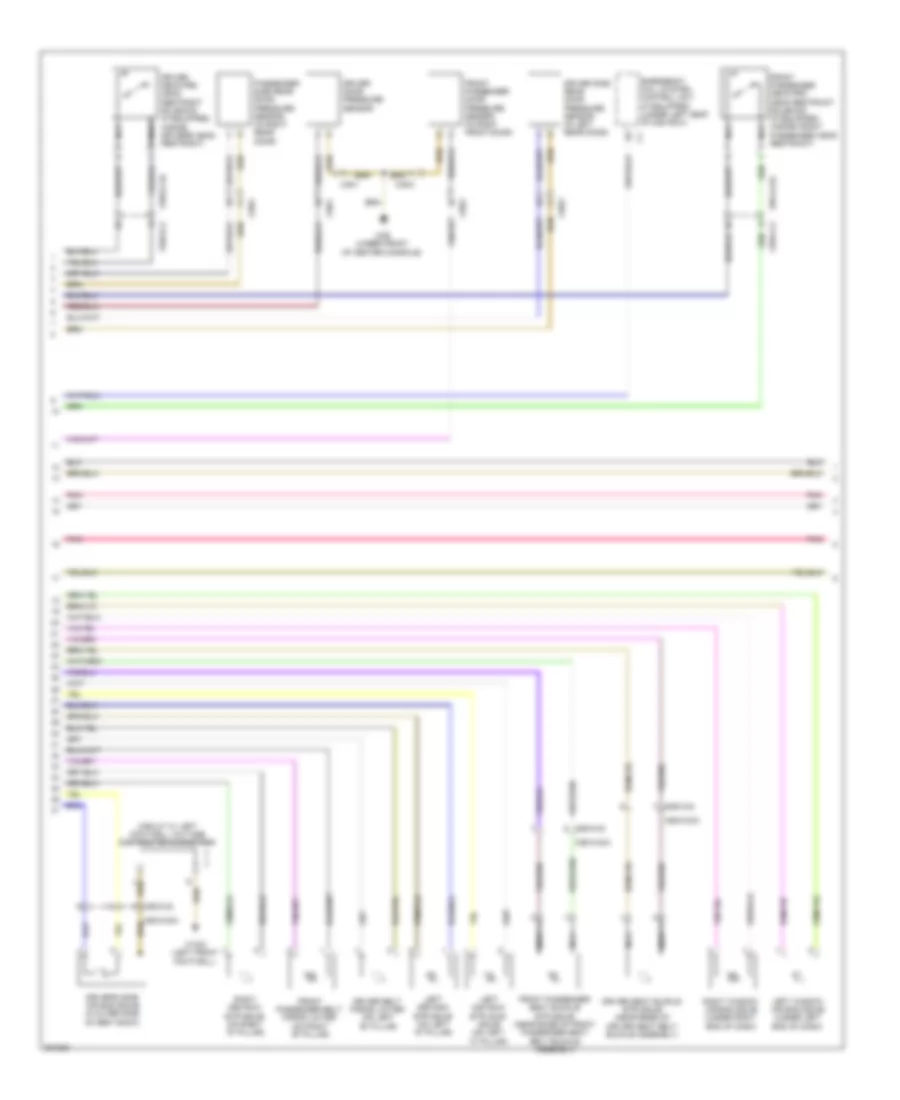 https://portal-diagnostov.com/license.html
Automotive Electricians Portal FZCO
Automotive Electricians Portal FZCO
https://portal-diagnostov.com/license.html
https://portal-diagnostov.com/license.html
Automotive Electricians Portal FZCO
Automotive Electricians Portal FZCOList of elements for Supplemental Restraint Wiring Diagram (2 of 3) for Mercedes-Benz GL350 2012:
- Circuit 31 left footwell voltage distributor connector
- Driver belt force limiter (on left "b" pillar)
- Driver door pressure sensor
- Driver neck-pro head restraint solenoid (if equipped) (inside driver's head restraint)
- Driver seat buckle etr squib (near base of driver seat belt buckle assembly)
- Driver side rear door pressure sensor (in left rear door)
- Driver's side air bag squib (in outer side of seat back)
- Emergency call system control unit (if equipped) (under left seat of 2nd row)
- Front passenger belt force limiter (on right "b" pillar)
- Front passenger door pressure sensor (in right front door)
- Front passenger neck-pro head restraint solenoid (if equipped) (inside front passenger head restraint)
- Front passenger seat buckle etr squib (near base of front passenger seat belt buckle assembly)
- Left 2nd row etr (gus) squib (on left "c" pillar)
- Left 3rd row etr squib (on left "d" pillar)
- Left window air bag squib (under left end of dash)
- Nca
- Passenger side rear door pressure sensor (in right rear door)
- Pnk
- Right 3rd row etr squib (on right "d" pillar)
- Right window air bag squib (under right end of dash)
- W15/2 (left front footwell)
- W26 (under front of center console)
- X35/1
- X35/2
- X35/3
- X35/4
- X55/3-c2
- X55/3-c2a
- X55/4-c2
- X55/4-c2a
Supplemental Restraint Wiring Diagram (3 of 3) for Mercedes-Benz GL350 2012
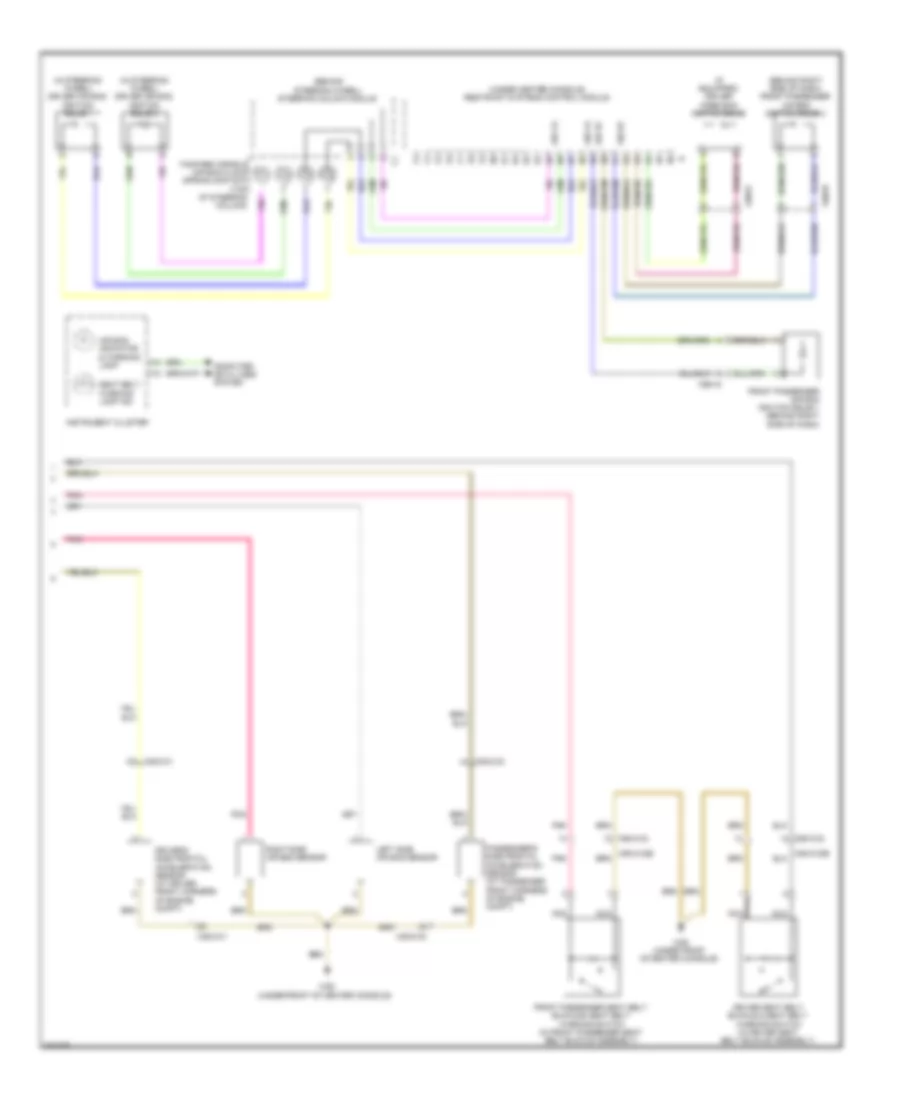 https://portal-diagnostov.com/license.html
Automotive Electricians Portal FZCO
Automotive Electricians Portal FZCO
https://portal-diagnostov.com/license.html
https://portal-diagnostov.com/license.html
Automotive Electricians Portal FZCO
Automotive Electricians Portal FZCOList of elements for Supplemental Restraint Wiring Diagram (3 of 3) for Mercedes-Benz GL350 2012:
- (behind right side of dash) front passenger air bag ignition squib 2
- (behind steering wheel) steering column module
- (if equipped) driver knee bag ignition squib
- (in steering wheel) driver air bag ignition squib 1
- (in steering wheel) driver air bag ignition squib 2
- (under center console) restraint systems control module
- Ab1 bf
- Ab1 fa
- Ab2 bf
- Ab2 fa
- Air bag indicator & warning lamp
- Computer data lines system
- D3 x25/2-c1
- Driver seat belt buckle & seat belt warning switch (in driver seat belt buckle assembly)
- Driver's side frontal acceleration sensor (at driver front corners of engine compt)
- Fanfare horns & air bag clock spring contact (top of steering column)
- Front passenger air bag ignition squib 1 (behind right side of dash)
- Front passenger seat belt buckle & seat belt warning switch (in front passenger seat belt buckle assembly)
- Instrument cluster
- J4 x25/2-c2
- Left side air bag sensor
- Nca
- Passenger's side frontal acceleration sensor (at passenger front corners of engine compt)
- Pnk
- Right side air bag sensor
- Seat belt warning lamp ind
- W26 (under front of center console)
- X25/2-c1
- X25/2-c2
- X55/3-c2
- X55/3-c2b
- X55/4-c2
- X55/4-c2b
- X99/15
- X99/17
TRANSMISSION
A/T Wiring Diagram for Mercedes-Benz GL350 2012
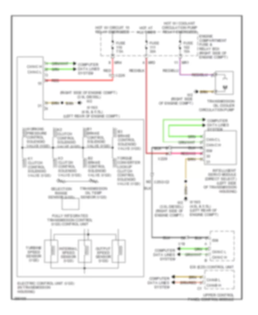 https://portal-diagnostov.com/license.html
Automotive Electricians Portal FZCO
Automotive Electricians Portal FZCO
https://portal-diagnostov.com/license.html
https://portal-diagnostov.com/license.html
Automotive Electricians Portal FZCO
Automotive Electricians Portal FZCOList of elements for A/T Wiring Diagram for Mercedes-Benz GL350 2012:
- (right side of engine compt) (3.0l diesel) w2
- B1 brake control solenoid valve (vgs)
- B2 brake control solenoid valve (vgs)
- B3 brake control solenoid valve (vgs)
- Can-b h
- Can-b l
- Can-c h
- Can-c l
- Computer data lines system
- Eis (ezs) control unit
- Electric control unit (vgs) (in transmission housing)
- Engine compartment fuse & relay box (right side of engine compt)
- Fully integrated transmission control (vgs) control unit
- Fuse 15a
- Fuse 30a
- Fuse 7.5a
- Hot at all times
- Hot w/ circuit 15 relay energized
- Hot w/ coolant circulation pump relay energized
- Intelligent servo module (direct select) (left side of transmission housing)
- Internal speed sensor (vgs)
- Ism
- K1 clutch control solenoid valve (vgs)
- K2 clutch control solenoid valve (vgs)
- K3 clutch control solenoid valve (vgs)
- M2 x25/2-c2
- Mr1
- Mr3
- Mr4
- Output speed sensor (vgs)
- Red
- Selection range sensor (vgs)
- Torque converter lockup clutch control solenoid valve (vgs)
- Transmission oil cooler circulation pump
- Transmission oil temp sensor (vgs)
- Turbine speed sensor (vgs)
- Upper control panel control module
- W16/3 (4.6l & 5.5l) (left rear of engine compt)
- W2 (3.0l diesel) (right side of engine compt)
- W2 (right side of engine compt)
- Working pressure control solenoid valve (vgs)
- X18
- X22/6
Rear Differential Lock Wiring Diagram for Mercedes-Benz GL350 2012
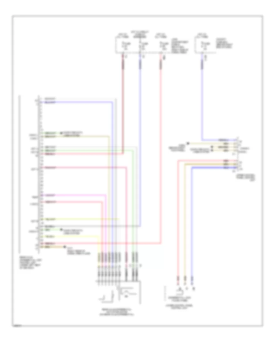 https://portal-diagnostov.com/license.html
Automotive Electricians Portal FZCO
Automotive Electricians Portal FZCO
https://portal-diagnostov.com/license.html
https://portal-diagnostov.com/license.html
Automotive Electricians Portal FZCO
Automotive Electricians Portal FZCOList of elements for Rear Differential Lock Wiring Diagram for Mercedes-Benz GL350 2012:
- (-)
- C13b
- Can-b h
- Can-b l
- Can-c h
- Can-c l
- Cockpit fuse box (behind right end of dash)
- Computer data lines system
- Differential lock thumb wheel
- Fuse 30a
- Fuse 5a
- H sig 1
- H sig 2
- Hot at all times
- Hot w/ circuit 15 relay energized
- Lin
- Load compartment fuse & relay box (right side of cargo area)
- Lower control panel control unit
- Mot a
- Mot b
- Ms4
- Nca
- Rear axle differential actuator motor (on rear axle differential)
- Rear axle differential lock control unit (under left seat of 3rd row)
- Red
- Temp
- Upper control panel control unit
- W29/2 (behind right kick panel)
- W7/7 (right rear of cargo area floor)
Transfer Case Wiring Diagram for Mercedes-Benz GL350 2012
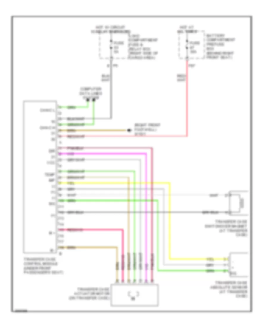 https://portal-diagnostov.com/license.html
Automotive Electricians Portal FZCO
Automotive Electricians Portal FZCO
https://portal-diagnostov.com/license.html
https://portal-diagnostov.com/license.html
Automotive Electricians Portal FZCO
Automotive Electricians Portal FZCOList of elements for Transfer Case Wiring Diagram for Mercedes-Benz GL350 2012:
- (+)
- (-)
- (right front footwell) w15/1
- Battery compartment prefuse box (behind right front seat)
- Can-c h
- Can-c l
- Computer data lines system
- Dir
- F87
- Fuse 30a
- Fuse 5a
- Hot at all times
- Hot w/ circuit 15 relay energized
- Imp
- Load compartment fuse & relay box (right side of cargo area)
- M +
- M -
- Sig
- Temp
- Transfer case absolute sensor (at transfer case)
- Transfer case actuator motor (on transfer case)
- Transfer case control module (under front passenger's seat)
- Transfer case switchover magnet (at transfer case)
- Vcc
TRUNK, TAILGATE, FUEL DOOR
Door Closing Assist Wiring Diagram for Mercedes-Benz GL350 2012
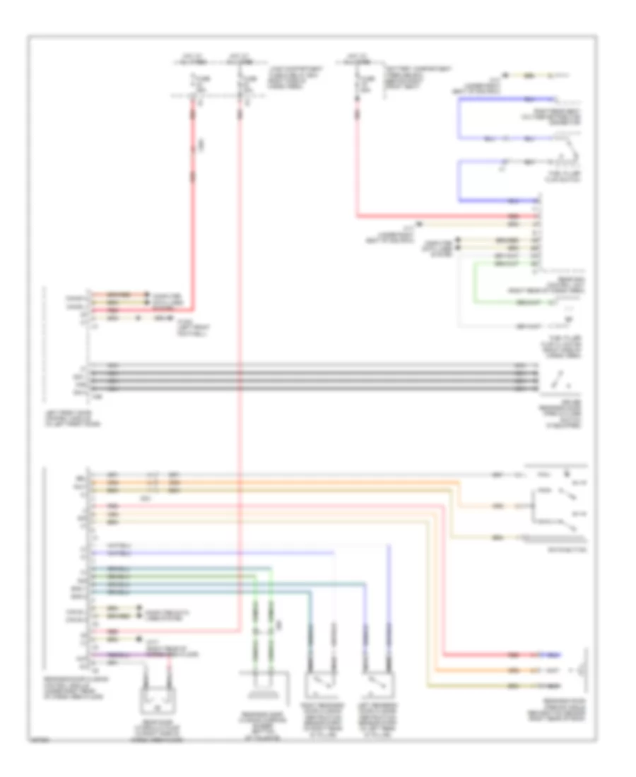 https://portal-diagnostov.com/license.html
Automotive Electricians Portal FZCO
Automotive Electricians Portal FZCO
https://portal-diagnostov.com/license.html
https://portal-diagnostov.com/license.html
Automotive Electricians Portal FZCO
Automotive Electricians Portal FZCOList of elements for Door Closing Assist Wiring Diagram for Mercedes-Benz GL350 2012:
- Auf
- Battery compartment prefuse box (behind right front seat)
- Bel
- C3b
- Can b h
- Can b l
- Can-b h
- Can-b l
- Computer data lines system
- Driver rear-end door open & close switch (if equipped)
- Eks 1
- Eks 2
- Fuel filler flap cl motor (right side of cargo area)
- Fuel filler flap switch
- Fuse 25a
- Fuse 30a
- Fuse 60a
- Hot at all times
- Ki58
- Left front door control module (in left front door)
- Left rear-end door closing obstruction sensor strip (in left rear "d" pillar)
- Load compartment fuse & relay box (right side of cargo area)
- Nca
- Rear door hydraulic pump (in right side of cargo area floor)
- Rear sam control unit (right rear of cargo area)
- Rear-end door closing control module (under right rear of cargo area floor)
- Rear-end door closing warning buzzer (bottom of tailgate)
- Rear-end door opening angle recognition sensor (right rear of roof)
- Red
- Right rear seat voltage distributor connector
- Right rear-end door closing obstruction sensor strip (in right rear "d" pillar)
- Rwt
- Rwts button
- Sig
- Sig 1
- Sig 2
- W15/2 (left front footwell)
- W17 (under right seat of 2nd row)
- W7/7 (right rear of cargo area floor)
- X35/1
- X8/4
WARNING SYSTEMS
Seat Belt Warning Wiring Diagram for Mercedes-Benz GL350 2012
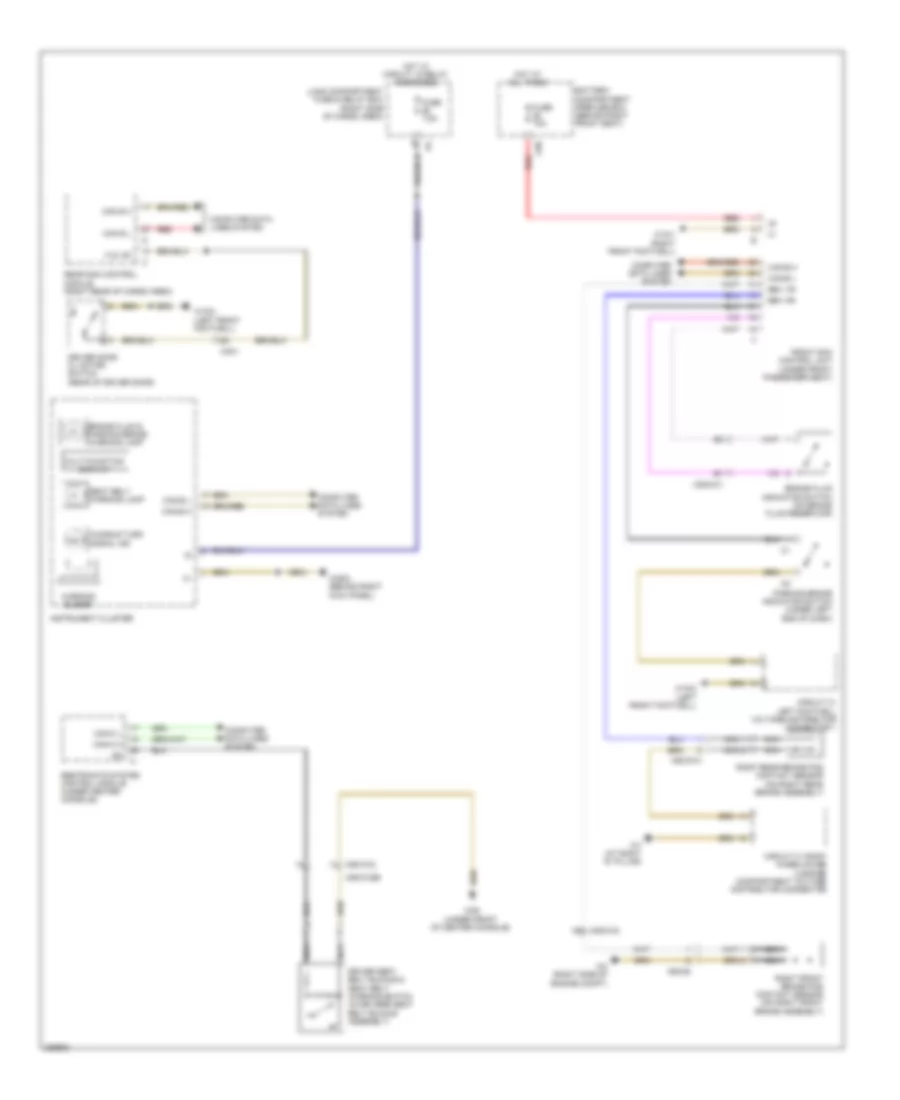 https://portal-diagnostov.com/license.html
Automotive Electricians Portal FZCO
Automotive Electricians Portal FZCO
https://portal-diagnostov.com/license.html
https://portal-diagnostov.com/license.html
Automotive Electricians Portal FZCO
Automotive Electricians Portal FZCOList of elements for Seat Belt Warning Wiring Diagram for Mercedes-Benz GL350 2012:
- Audible turn signal ind
- Battery compartment prefuse box (behind right front seat)
- Bbv hr
- Bbv vr
- Brake fluid & parking brake warning lamp
- Brake fluid indicator switch (on brake fluid reservoir)
- C88
- Can b h
- Can b l
- Can-b h
- Can-b l
- Can-c h
- Can-c l
- Circuit 31 left footwell voltage distributor connector 1
- Circuit 31 right wheelhouse luggage compartment voltage distributor connector
- Computer data lines system
- Driver door cl motor/ switch (rear of driver door)
- Driver seat belt buckle & seat belt warning switch (in driver's seat belt buckle assembly)
- F zv df
- Front sam control unit (under front passenger seat)
- Fuse 7.5a
- Fuse 70a
- H6 x25/2-c2
- Hot at all times
- Hot w/ circuit 15 relay energized
- Instrument cluster
- Load compartment fuse & relay box (right side of cargo area)
- Multi-function display
- Nca
- Parking brake indicator switch (under left end of dash)
- Rear sam control module (right rear of cargo area)
- Red
- Restraints system control module (under center console)
- Right front brake pad contact sensor (on right front brake assembly)
- Right rear brake pad contact sensor (on right rear brake assembly)
- Seat belt warning lamp
- W15/1 (right front footwell)
- W15/2 (left front footwell)
- W2 (right side of engine compt)
- W26 (under front of center console)
- W29/2 (behind right kick panel)
- W7 (at right "d" pillar)
- Warning buzzer
- X25/2-c1
- X35/1
- X55/3-c2
- X55/3-c2b
- X62/33-a
- X62/36
Tire Pressure Monitoring Wiring Diagram for Mercedes-Benz GL350 2012
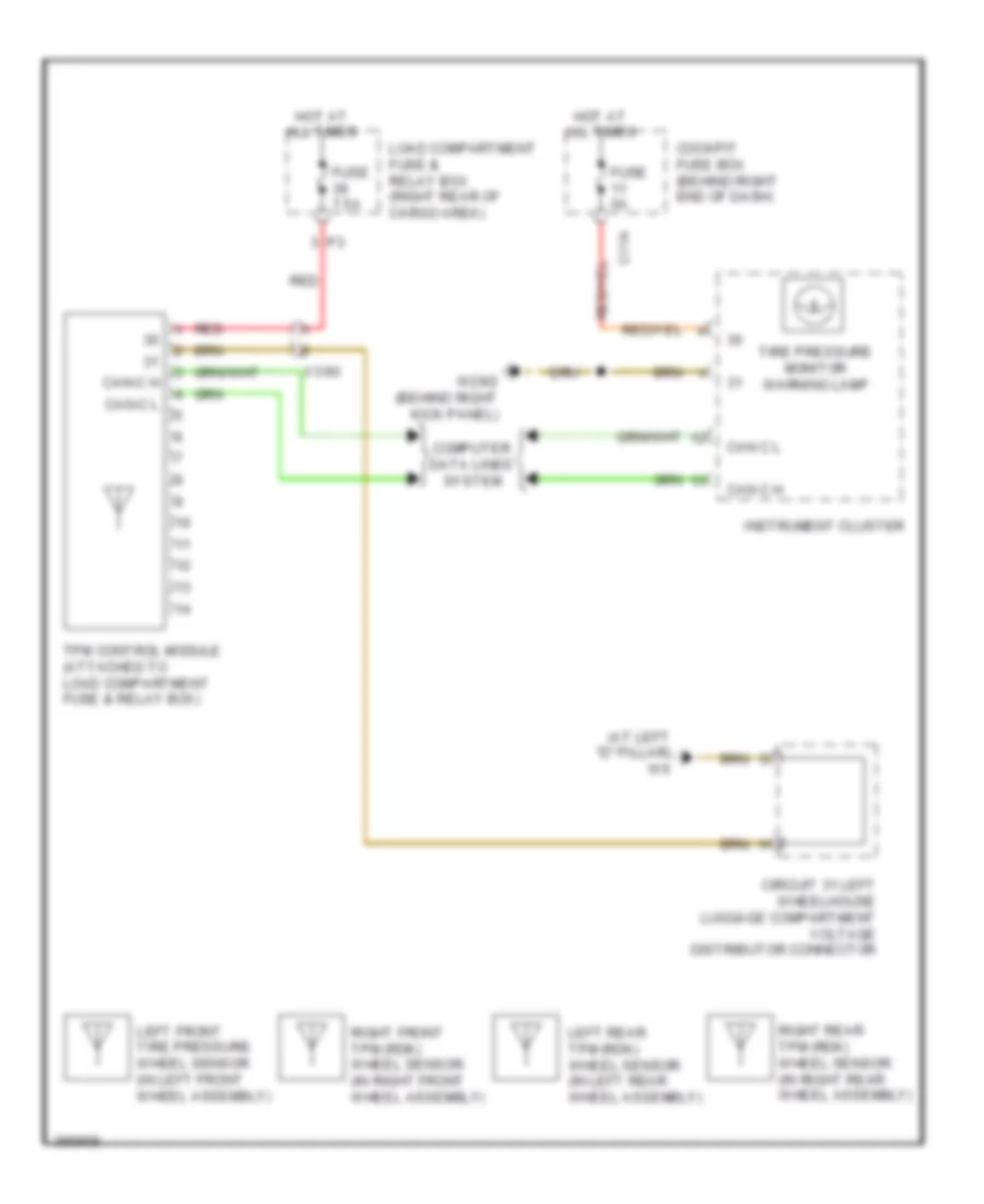 https://portal-diagnostov.com/license.html
Automotive Electricians Portal FZCO
Automotive Electricians Portal FZCO
https://portal-diagnostov.com/license.html
https://portal-diagnostov.com/license.html
Automotive Electricians Portal FZCO
Automotive Electricians Portal FZCOList of elements for Tire Pressure Monitoring Wiring Diagram for Mercedes-Benz GL350 2012:
- (at left "d" pillar) w6
- C11a
- Can c h
- Can c l
- Can-c h
- Can-c l
- Circuit 31 left wheelhouse luggage compartment voltage distributor connector
- Cockpit fuse box (behind right end of dash)
- Computer data lines system
- Fuse 5a
- Fuse 7.5a
- Hot at all times
- Instrument cluster
- Left front tire pressure wheel sensor (in left front wheel assembly)
- Left rear tpm (rdk) wheel sensor (in left rear wheel assembly)
- Load compartment fuse & relay box (right rear of cargo area)
- Red
- Right front tpm (rdk) wheel sensor (in right front wheel assembly)
- Right rear tpm (rdk) wheel sensor (in right rear wheel assembly)
- Tire pressure monitor warning lamp
- Tpm control module (attached to load compartment fuse & relay box)
- W29/2 (behind right kick panel)
- X1/60
WIPER/WASHER
Front Wiper/Washer Wiring Diagram for Mercedes-Benz GL350 2012
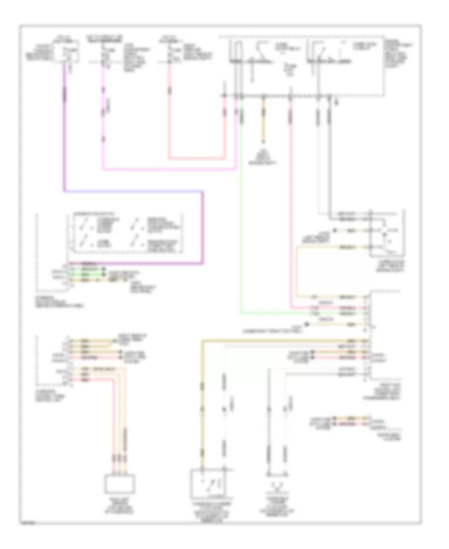 https://portal-diagnostov.com/license.html
Automotive Electricians Portal FZCO
Automotive Electricians Portal FZCO
https://portal-diagnostov.com/license.html
https://portal-diagnostov.com/license.html
Automotive Electricians Portal FZCO
Automotive Electricians Portal FZCOList of elements for Front Wiper/Washer Wiring Diagram for Mercedes-Benz GL350 2012:
- (right rear of cargo area) w48/3
- 87a
- C13a
- Can-b h
- Can-b l
- Can-c h
- Can-c l
- Cockpit fuse box (behind right end of dash)
- Combination switch
- Computer data lines system
- Data
- Engine compartment fuse & relay box (right side of engine compt)
- Front prefuse (right rear of engine compt)
- Front sam control unit (under front passenger's seat)
- Fuse 100a
- Fuse 30a
- Fuse 5a
- Hot at all times
- Hot w/ circuit 15r relay energized
- Instrument cluster
- Load compartment fuse & relay box (right side of cargo area)
- Mr1
- Overhead control panel control unit
- Rain/light sensor (top center of windshield)
- Rear end door intermittent wash switch
- Rear end door window washer system switch
- Red
- Steering column module (behind steering wheel)
- W15/1 (under right front footwell)
- W16/3 (left rear of engine compt)
- W2 (right side of engine compt)
- W29/2 (behind right kick panel)
- Windshield washer fluid level indicator switch (in washer fluid reservoir)
- Windshield washer fluid pump (on washer fluid reservoir)
- Windshield washer system switch
- Wiper level 1/2 relay
- Wiper motor (left rear of engine compt)
- Wiper on/off relay
- Wiper switch
- X25/2-c1
- X25/2-c2
Headlamp Washer Wiring Diagram for Mercedes-Benz GL350 2012
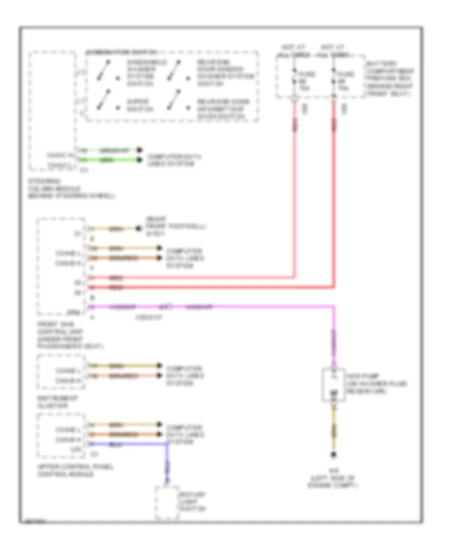 https://portal-diagnostov.com/license.html
Automotive Electricians Portal FZCO
Automotive Electricians Portal FZCO
https://portal-diagnostov.com/license.html
https://portal-diagnostov.com/license.html
Automotive Electricians Portal FZCO
Automotive Electricians Portal FZCOList of elements for Headlamp Washer Wiring Diagram for Mercedes-Benz GL350 2012:
- (behind right front seat)
- (right front footwell) w15/1
- Battery compartment prefuse box
- C88
- C89
- Can-b h
- Can-b l
- Can-c h
- Can-c l
- Combination switch
- Computer data lines system
- Front sam control unit (under front passenger's seat)
- Fuse 70a
- Hcs pump (on washer fluid reservoir)
- Hot at all times
- Instrument cluster
- Lin
- Rear end door intermittent wash switch
- Rear end door window washer system switch
- Red
- Rotary light switch
- Sra
- Steering column module (behind steering wheel)
- Upper control panel control module
- W9 (left side of engine compt)
- Windshield washer system switch
- Wiper switch
- X25/2-c1
Rear Wiper/Washer Wiring Diagram for Mercedes-Benz GL350 2012
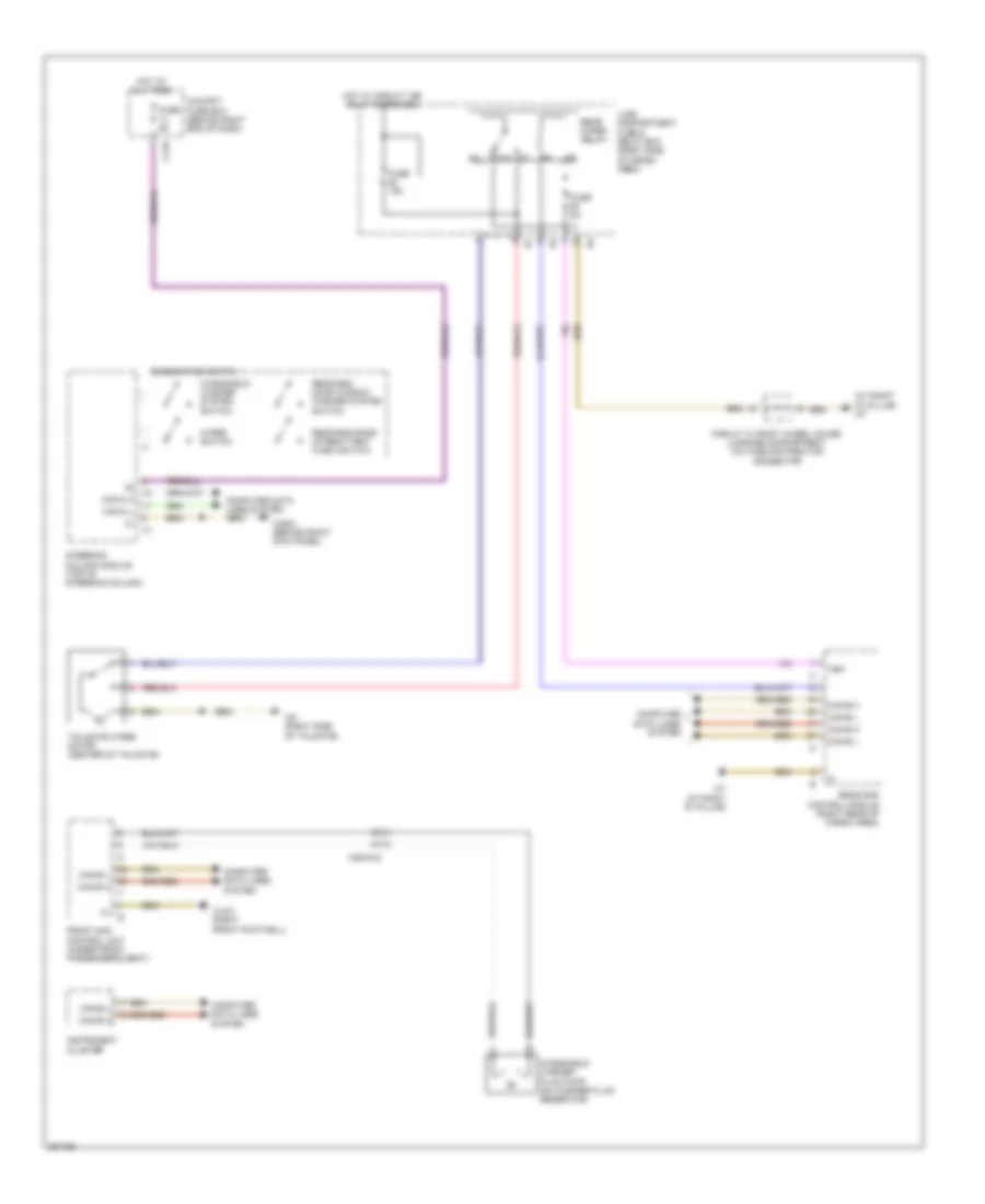 https://portal-diagnostov.com/license.html
Automotive Electricians Portal FZCO
Automotive Electricians Portal FZCO
https://portal-diagnostov.com/license.html
https://portal-diagnostov.com/license.html
Automotive Electricians Portal FZCO
Automotive Electricians Portal FZCOList of elements for Rear Wiper/Washer Wiring Diagram for Mercedes-Benz GL350 2012:
- (at right "d" pillar) w7
- 15r1
- 87a
- C13a
- Can-b h
- Can-b l
- Can-c h
- Can-c l
- Circuit 31 right wheel house luggage compartment voltage distributor connector
- Cockpit fuse box (behind right end of dash)
- Combination switch
- Computer data lines system
- Front sam control unit (under front passenger's seat)
- Fuse 15a
- Fuse 5a
- Hot at all times
- Hot w/ circuit 15r relay energized
- Instrument cluster
- Load compartment fuse & relay box (right side of cargo area)
- Rear end door intermittent wash switch
- Rear end door window washer system switch
- Rear sam control module (right rear of cargo area)
- Rear wiper relay
- Steering column module (top of steering column)
- Tailgate wiper motor (center of tailgate)
- W15/1 (right front footwell)
- W29/2 (behind right kick panel)
- W7 (at right "d" pillar)
- W8 (right side of tailgate)
- Windshield washer fluid pump (on washer fluid reservoir)
- Windshield washer system switch
- Wiper switch
- X25/2-c2

 Čeština
 Dansk
Dansk Deutsch
 Ελληνικά
 English
 English
 Español
 Suomi
Suomi Français
 Français
 עברית
עברית Hrvatski
 Magyar
 Italiano
 日本語
日本語 Nederlands
 Polski
 Português
 Português
 Română
 Русский
 Slovenčina
 Slovenščina
 Svenska
 Türkçe
 中文 (中国)
