AIR CONDITIONING
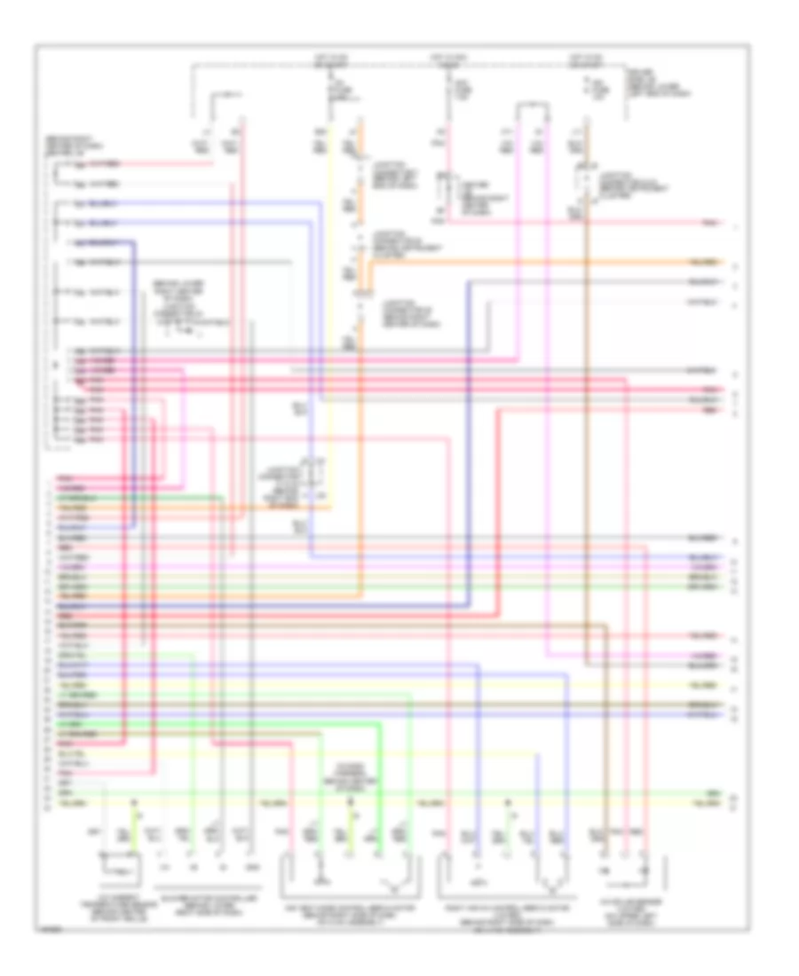
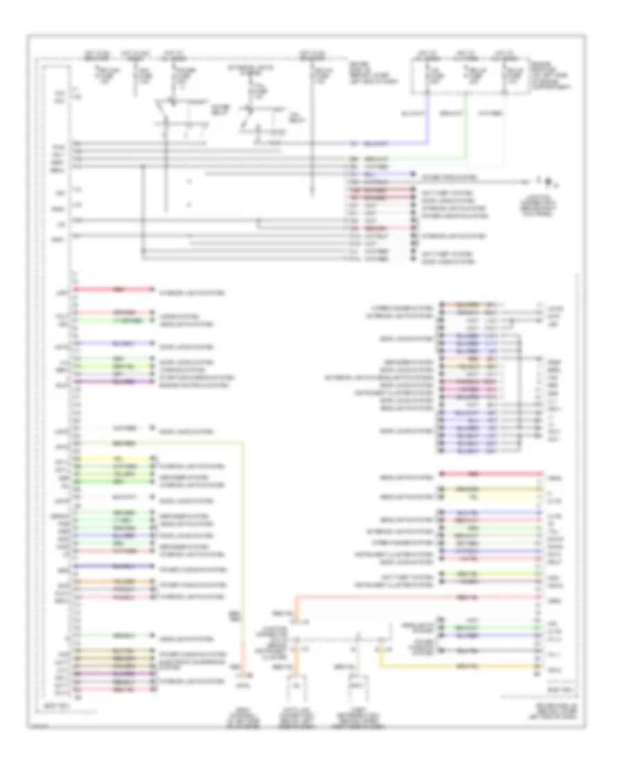
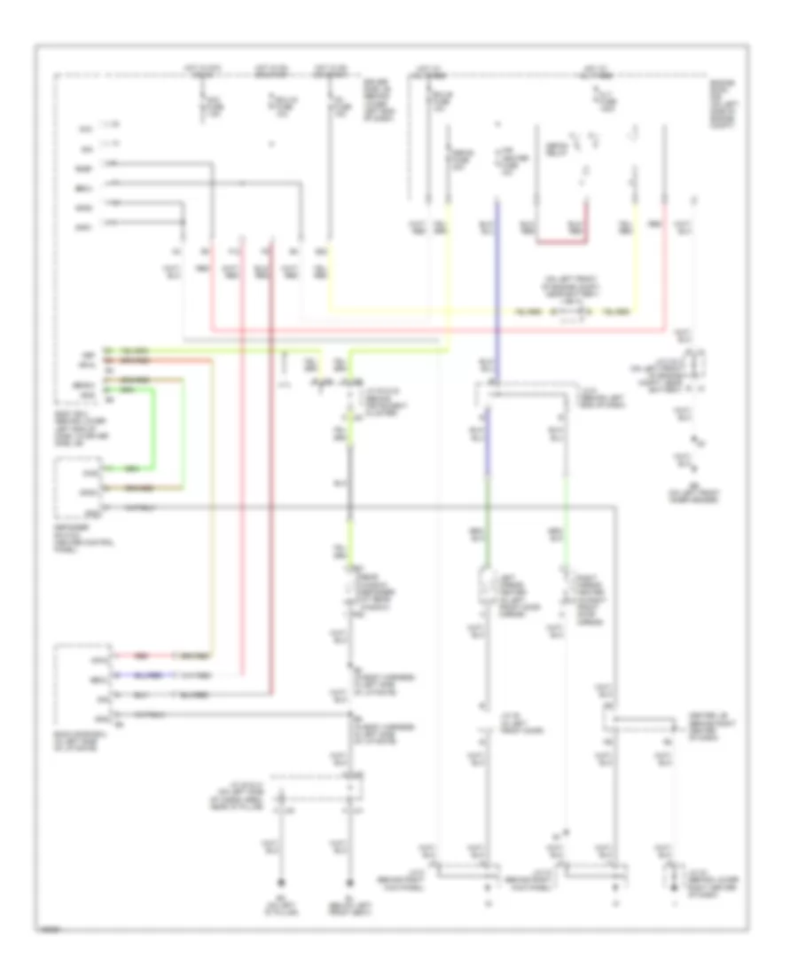
Automatic A/C Wiring Diagram (1 of 3) for Toyota 4Runner SR5 2004
 https://portal-diagnostov.com/license.html
Automotive Electricians Portal FZCO
Automotive Electricians Portal FZCO
https://portal-diagnostov.com/license.html
https://portal-diagnostov.com/license.html
Automotive Electricians Portal FZCO
Automotive Electricians Portal FZCO
List of elements for Automatic A/C Wiring Diagram (1 of 3) for Toyota 4Runner SR5 2004:
- (on right front of engine compartment) pressure switch
- A/c control assembly
- A/c room temperature sensor (behind lower left center of dash)
- A16
- A17
- A26
- A27
- Acld
- Acs
- Aif
- Air
- Air inlet control servo motor (behind upper right end of dash, on hvac assembly)
- Air mix control servo motor (sr5 grade) left air mix control servo motor (limited) (sr5 grade: behind right side of dash, on hvac assembly) (limited: behind left center of dash, on hvac assembly)
- Amcdr or amc
- Amcpa
- Amhdr or amh
- Amhpa
- Aod
- Aof
- Blower motor (behind lower right side of dash, on hvac assembly)
- Blw
- Dmin
- Dmot
- Dome fuse 10a
- Eb (on left front inner fender)
- Ecu-b fuse 10a
- Engine room r/b (on left side of engine compartment)
- Gnd
- Heater 2 fuse 7.5a
- Heater fuse 60a
- Heater relay
- Hot at all times
- I6 (in dash harness, behind center of dash)
- Junction connector 1 (on left front of engine compartment, near battery)
- Junction connector 2 & 3 (on left front of engine compartment, near battery)
- Junction connector 7 (behind left end of dash)
- Limited sr5 grade
- Lin1
- Pnk
- Psw
- Red
- Spd
- Tam
- The
- Tpdr or tp
- Tpi
- Tpo
- Tppa
- Tsdr or ts
- Tspa
- Twi
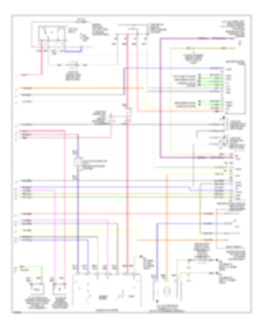
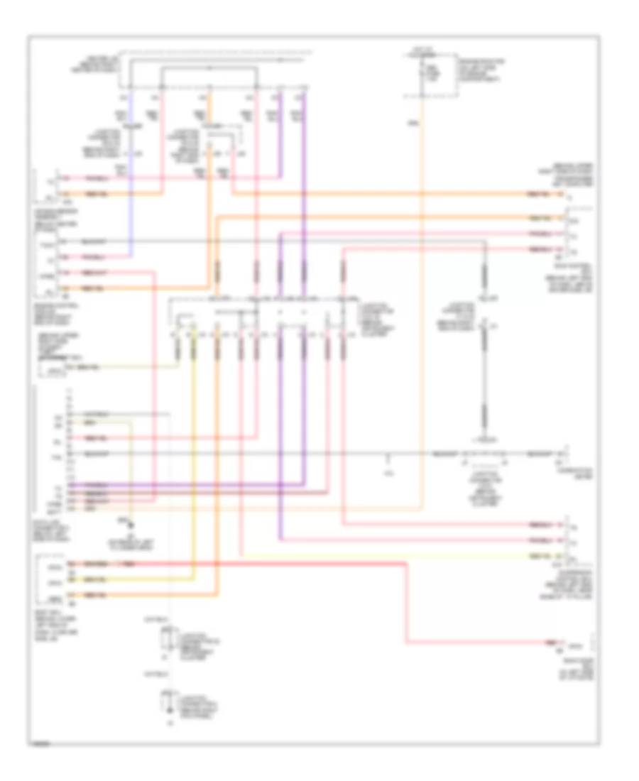
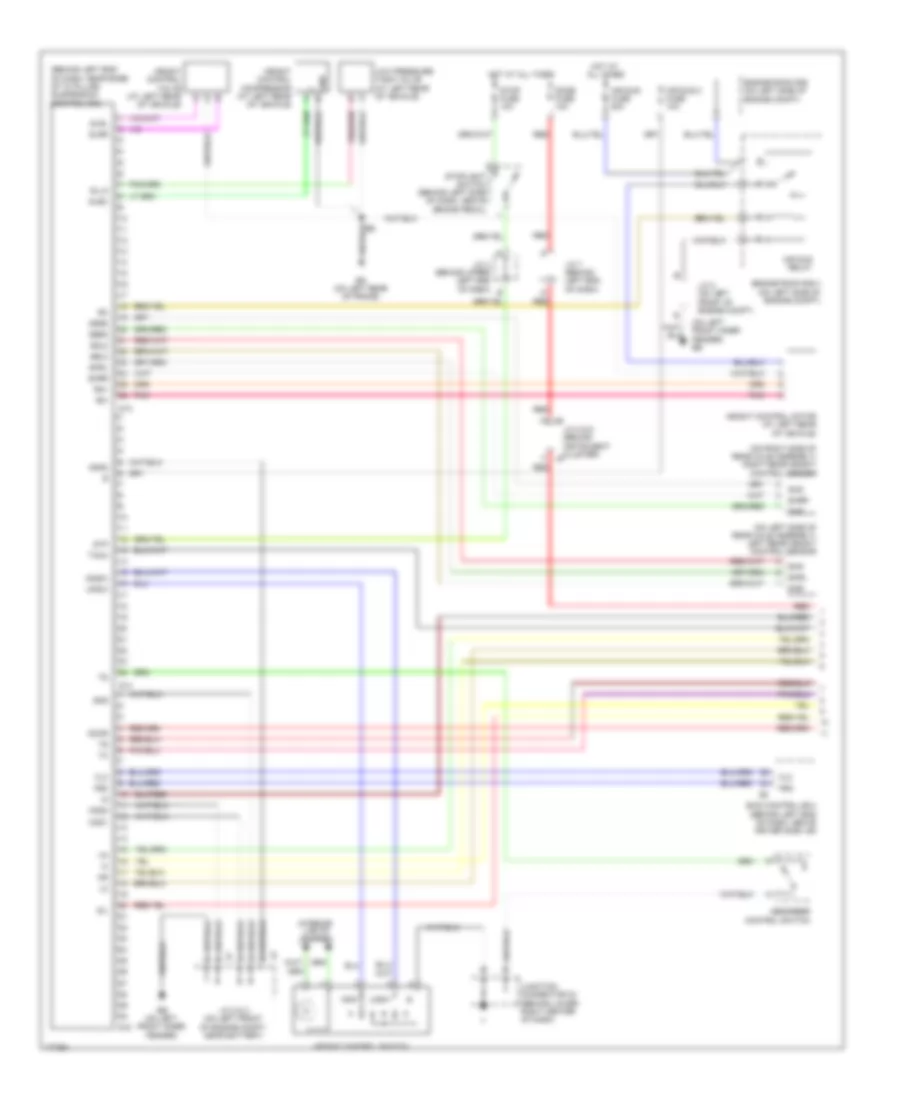
Automatic A/C Wiring Diagram (2 of 3) for Toyota 4Runner SR5 2004
 https://portal-diagnostov.com/license.html
Automotive Electricians Portal FZCO
Automotive Electricians Portal FZCO
https://portal-diagnostov.com/license.html
https://portal-diagnostov.com/license.html
Automotive Electricians Portal FZCO
Automotive Electricians Portal FZCOList of elements for Automatic A/C Wiring Diagram (2 of 3) for Toyota 4Runner SR5 2004:
- (behind lower
- (behind right center of dash) center j/b
- (in dash harness, behind center of dash)
- A/c ambient temperature sensor (behind center of front grille)
- A/c solar sensor (limited) (on upper left side of dash)
- Acc fuse 7.5a
- Air vent mode control servo motor (behind right side of dash, on hvac assembly)
- Blower motor controller (behind lower right side of dash)
- Center j/b (behind right center of dash)
- Driver side j/b (behind lower left end of dash)
- E20
- Gnd
- Hot in acc
- Hot in on
- Hot in on
- Ig1 fuse 15a
- Ign fuse 10a
- J11
- J31
- J32
- Junction connector 20 (behind instrument cluster)
- Junction connector 24
- Junction connector 25 (behind right center of dash)
- Junction connector 31 & 32 (behind right end of dash)
- Junction connector 7 (behind left end of dash)
- Junction connector 8 & 9 (behind instrument cluster)
- K11
- Or on
- Or start
- Pnk
- Red
- Right air mix control servo motor (limited) (behind right side of dash, on hvac assembly)
- Right center of dash)
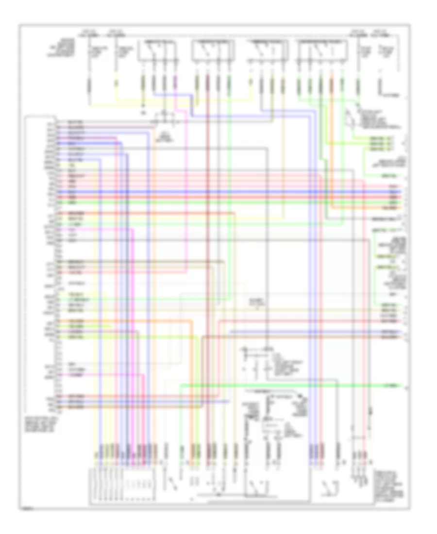
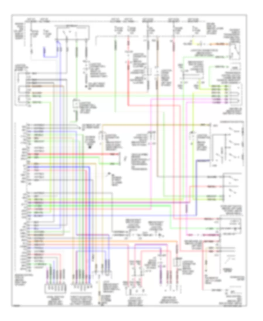
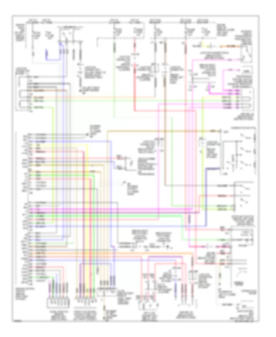
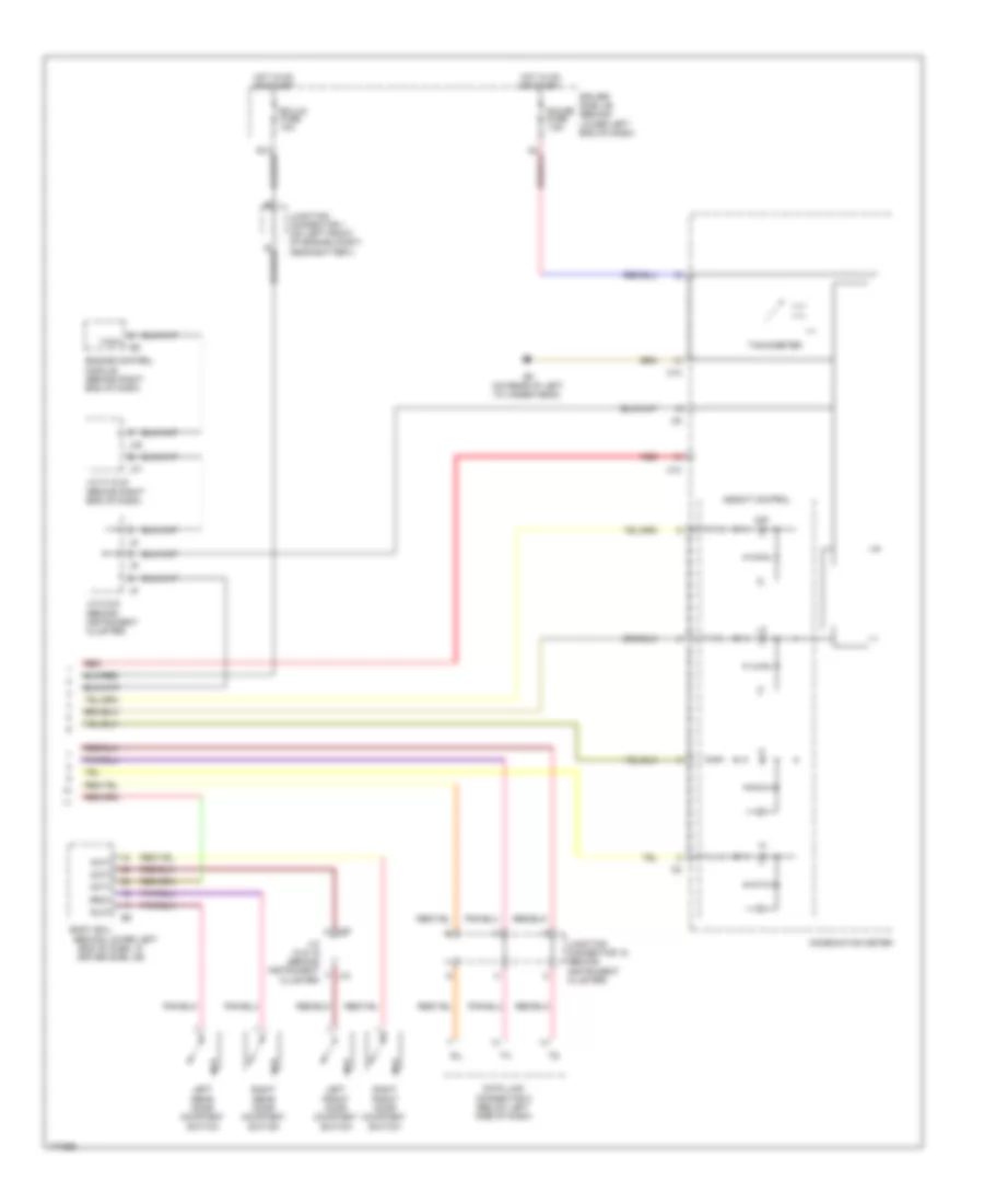
Automatic A/C Wiring Diagram (3 of 3) for Toyota 4Runner SR5 2004
 https://portal-diagnostov.com/license.html
Automotive Electricians Portal FZCO
Automotive Electricians Portal FZCO
https://portal-diagnostov.com/license.html
https://portal-diagnostov.com/license.html
Automotive Electricians Portal FZCO
Automotive Electricians Portal FZCOList of elements for Automatic A/C Wiring Diagram (3 of 3) for Toyota 4Runner SR5 2004:
- (4.0l: on upper left side of engine) (4.7l: on right front of engine) engine coolant temperature sensor
- (behind right side of dash, near firewall grommet)
- (on rear of left cylinder head)
- (on rear of right cylinder head)
- 4.0l
- 4.7l
- A/c evaporator temperature sensor (behind right side of dash, on hvac assembly)
- A/c lock sensor & magnetic clutch (on a/c compressor assembly)
- A/c solar sensor (sr5 grade) (on upper left side of dash)
- A/cs
- Acc
- Acc cut
- Accr
- Acld
- Acmg
- All times
- Anti-theft system
- C10
- Center j/b (behind right center of dash)
- Combination meter
- D j10
- Defogger system
- Dfsw
- Dind
- Ef (on rear of left cylinder head)
- Efi fuse 20a
- End of dash)
- Engine control module (behind right
- Engine room r/b (on left side of engine compartment)
- F j9
- Gnd
- H j8
- Heater control panel
- Hot at
- I8 (in dash harness, behind upper right side of dash)
- Ig+
- Ill+
- Ill-
- Interior lights system
- J11 i
- J33
- J34
- Junction connector 10 & 11 (behind instrument cluster)
- Junction connector 27
- Junction connector 33 & 34 (behind right end of dash)
- Junction connector 37 (behind right kick panel)
- Junction connector 6 (behind left end of dash)
- Junction connector 8 & 9 (behind instrument cluster)
- Lcki
- Lin-b
- Mg clt relay
- Pbew
- Pnk
- Red
- Relay
- Sind
- Speedo meter
- Temp
- The
- Thw
- Thwo
- Warning system
ANTI-LOCK BRAKES
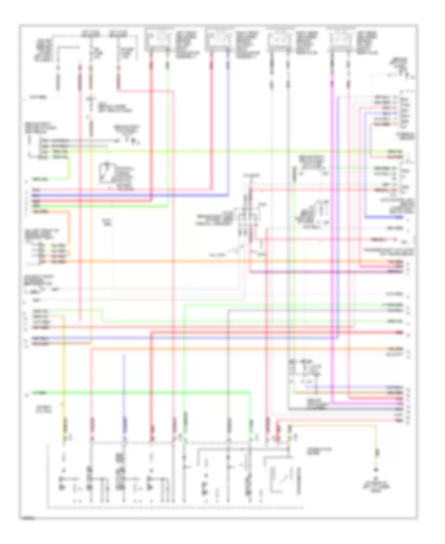
Anti-lock Brakes Wiring Diagram (1 of 3) for Toyota 4Runner SR5 2004
 https://portal-diagnostov.com/license.html
Automotive Electricians Portal FZCO
Automotive Electricians Portal FZCO
https://portal-diagnostov.com/license.html
https://portal-diagnostov.com/license.html
Automotive Electricians Portal FZCO
Automotive Electricians Portal FZCOList of elements for Anti-lock Brakes Wiring Diagram (1 of 3) for Toyota 4Runner SR5 2004:
- (on right front inner fender) ea
- +b1
- +bo
- Abs & ba & trac & vsc actuator (at left rear of engine compt, beside brake master cylinder)
- Abs mtr fuse 40a
- Abs mtr relay
- Abs sol fuse 50a
- Abs sol relay
- Ast
- B j3
- Driver side j/b (behind lower left end of dash)
- E24
- Eb (on left front inner fender)
- Ecu-b fuse 10a
- Engine room r/b (on left side of engine compartment)
- Ex13
- Except 4.0l 2wd
- Fl+
- Fl-
- Fr+
- Fr-
- Gnd
- Gnd1
- Gnd2
- Hdcw
- Hot at all times
- Ig2
- J/c 1 (near battery)
- J/c 2 & 3 (near battery)
- J/c 2 & 3 (on left front of engine compt, near battery)
- J/c 22 & 23 (behind instrument cluster)
- J/c 4 (behind upper left end of dash)
- J12
- J2 a
- J3 a
- Mr1
- Mr2
- Mss
- Mt+
- Mt-
- Mtt
- Nca
- Pmc
- Pnk
- R1+
- R2+
- Red
- S10
- Sa1
- Sa2
- Sa3
- Sflh
- Sflr
- Sfrh
- Sfrr
- Skid control ecu (behind left end of dash, above driver side j/b)
- Srlh
- Srlr
- Srrh
- Srrr
- Stop fuse 10a
- Stop lp ctrl relay
- Stoplight switch (behind left side of dash, above brake pedal)
- Stpo
- Str
- Trc mtr relay
- Trig
- Vcm
- Vout
Anti-lock Brakes Wiring Diagram (2 of 3) for Toyota 4Runner SR5 2004
 https://portal-diagnostov.com/license.html
Automotive Electricians Portal FZCO
Automotive Electricians Portal FZCO
https://portal-diagnostov.com/license.html
https://portal-diagnostov.com/license.html
Automotive Electricians Portal FZCO
Automotive Electricians Portal FZCOList of elements for Anti-lock Brakes Wiring Diagram (2 of 3) for Toyota 4Runner SR5 2004:
- (2wd) (4wd)
- (behind instrument cluster)
- (behind left kick panel) j/c 5
- (behind right center of dash) center j/b
- (behind right end of dash) j/c 31 & 32
- (behind right kick panel) j/c 37
- (on left front of engine compt, near battery) j/c 1
- (on right front of engine) add actuator
- 4.0l 4wd
- 4wd
- 4wd control ecu (behind lower right end of dash)
- Abs ind
- Add
- Bat
- Brake ind
- C10
- C11
- Cdl
- Combination meter
- Dac ind
- Downhill assist control switch (except 4.0l 2wd)
- Driver side j/b (behind lower left end of dash)
- E23
- Ef (on rear of left cylinder head)
- Ess
- Except 4.0l 2wd
- F10
- Gauge fuse 7.5a
- Hot in on or start
- Ig1
- Ign fuse 10a
- Ind2
- J/c 20 & 21 (4wd)
- J/c 28 (behind right side of dash, near firewall grommet)
- J/c 29 & 30 (behind right end of dash)
- J/c 4 (behind upper left end of dash)
- J20 b
- J21 d
- J29 f
- J30 h
- J31
- J32
- Left front abs speed sensor (on left front spindle/hub assembly)
- Left rear abs speed sensor (on left side of rear axle)
- Pnk
- Red
- Right front abs speed sensor (on right front spindle/hub assembly)
- Right rear abs speed sensor (on right side of rear axle)
- Slip ind
- Speedometer
- Ss1+
- Ss1-
- Steering sensor
- Trac off ind vsc off ind
- Transfer shift actuator (on transmission)
- Trig
- Vsc trac ind
Anti-lock Brakes Wiring Diagram (3 of 3) for Toyota 4Runner SR5 2004
 https://portal-diagnostov.com/license.html
Automotive Electricians Portal FZCO
Automotive Electricians Portal FZCO
https://portal-diagnostov.com/license.html
https://portal-diagnostov.com/license.html
Automotive Electricians Portal FZCO
Automotive Electricians Portal FZCOList of elements for Anti-lock Brakes Wiring Diagram (3 of 3) for Toyota 4Runner SR5 2004:
- (behind instrument cluster) j/c 18 & 19
- B j18
- Brl
- Csw
- D/g
- Data link connector 3 (below left side of dash)
- Dome fuse 10a
- Driver side j/b (behind lower left end of dash)
- E j22
- E12
- E20
- Ecu-ig fuse 10a
- Eng+
- Eng-
- Engine control module (behind right end of dash)
- Engine room r/b (on left side of engine compartment)
- Ex1
- Exi3
- Exi4
- Flo
- Fro
- G j20
- Gl1
- Gl2
- Gnd3
- Gnd4
- Gss
- Gyaw
- Hdcs
- Hot at all times
- Hot in on or start
- Ig1
- Ig1 fuse 15a
- Ind
- J/c 1 (on left front of engine compt, near battery)
- J/c 12 & 13 (behind instrument cluster)
- J/c 20 & 21 (behind instrument cluster)
- J/c 22 & 23 (behind instrument cluster)
- J/c 25 (behind right center of dash)
- J/c 35 (behind right end of dash)
- J/c 5 (behind right kick panel)
- J/c 7 (behind left end of dash)
- J/c 8 & 9 (behind instrument cluster)
- J/c 8 (behind instrument cluster)
- J12
- J13
- J18
- J19
- J19 j/c 18 & 19 (behind instrument cluster) j18 c
- J20 g
- J21 g
- J28
- Nca
- Neo
- Park/neutral position switch (on right side of transmission)
- Parking brake switch (behind upper left end of dash)
- Pkb
- Pnk
- Red
- Rl+
- Rl-
- Rr+
- Rr-
- S15
- Sil
- Skid control ecu (behind left end of dash, above driver side j/b)
- Sp1
- Ss1+
- Ss1-
- Stp
- Stp2
- Suspension control ecu (behind left end of dash, near base of ``a" pillar)
- Trac off switch (except 4.0l 4wd)
- Trc+
- Trc-
- Vsc warning buzzer (left side of dash)
- Vscw
- Vys
- Yaw
- Yaw rate sensor (below front of center console)
- Yaw2
- Yss
ANTI-THEFT
Forced Entry Wiring Diagram (1 of 2) for Toyota 4Runner SR5 2004
 https://portal-diagnostov.com/license.html
Automotive Electricians Portal FZCO
Automotive Electricians Portal FZCO
https://portal-diagnostov.com/license.html
https://portal-diagnostov.com/license.html
Automotive Electricians Portal FZCO
Automotive Electricians Portal FZCOList of elements for Forced Entry Wiring Diagram (1 of 2) for Toyota 4Runner SR5 2004:
- (below left front seat)
- (w/ drl)
- (w/o drl)
- Acc
- Acc fuse 7.5a
- Act+
- Act-
- Actd
- B10
- Bdr1
- Becu
- Body ecu
- Bzr
- Bzr2
- C10
- Center j/b (behind right center of dash)
- Combination meter
- Dcty
- Door control receiver (on left "d" pillar, behind trim)
- Door ind
- Driver side j/b (behind lower left end of dash)
- Drlp
- E10
- Ecu-ig fuse 10a
- Exterior lights
- F j18
- F12
- Gauge fuse 7.5a
- Gnd
- Gnd1
- Gnd2
- H j19
- Haz
- Haz/ ehw
- Headlights system
- Horn relay
- Horns system
- Hot at all times
- Hot in on or acc
- Hot in on or start
- Hrly
- Ile
- Interior lights system
- J/c 14 (behind instrument cluster)
- J/c 18 & 19 (behind instrument cluster)
- J/c 24 (behind lower right center of dash)
- J/c 40 & 41 (on left side of cargo area, near ``d" pillar)
- J/c 7 (behind left end of dash)
- J14
- J28
- J40
- J41
- K10
- K13
- K15
- Ksw
- L10
- L11
- L16
- L18
- L22
- L23
- Left front door courtesy switch (in left "b" pillar)
- Left rear door courtesy switch (bottom of left "c" pillar)
- Lmry
- Lsr
- Lswd
- Lswp
- Mpx2
- Mpx3
- Pcty
- Power fuse 30a
- Prg
- Rda
- Red
- Right front door courtesy switch (on right "b" pillar)
- Right rear door courtesy switch (bottom of right "c" pillar)
- Rlcy
- Rrcy
- Secu/horn fuse 10a
- Security indicator light
- Sig
- Sind
- Sr5 grade
- System
- Tail relay
- Tout
- Trly
- Turn signal flasher relay (behind lower left end of dash, behind driver side j/b)
- Ul3
- Wireless door lock buzzer (on left rear of of engine compt)
Forced Entry Wiring Diagram (2 of 2) for Toyota 4Runner SR5 2004
 https://portal-diagnostov.com/license.html
Automotive Electricians Portal FZCO
Automotive Electricians Portal FZCO
https://portal-diagnostov.com/license.html
https://portal-diagnostov.com/license.html
Automotive Electricians Portal FZCO
Automotive Electricians Portal FZCOList of elements for Forced Entry Wiring Diagram (2 of 2) for Toyota 4Runner SR5 2004:
- (on left front inner fender) eb
- +b1
- +b2
- Act+
- Act-
- Back door courtesy switch, back door half latch switch, back door lock detection switch & back door lock motor (in left side of tailgate)
- Back door ecu (in left side of liftgate)
- Back door power window motor (in left side of tailgate)
- Bddn
- Bdr
- Bdup
- Becu
- Bo (on left ``d" pillar)
- Dome fuse 10a
- Dome relay
- Dr/lck fuse 20a
- Dswh
- Ecu-b fuse 10a
- Engine hood courtesy switch (at center front of engine compt, near hood latch)
- Engine room r/b (on left side of engine compartment)
- Full
- Gnd
- Half
- Horn
- Horn fuse 10a
- Horns system
- Hot at all times
- Ic+
- Ic-
- Ic1
- Ic2
- Ind
- Interior lights system
- J/c 18 & 19 (behind instrument cluster)
- J/c 14 & 15 (behind instrument cluster)
- J/c 15 (behind instrument cluster)
- J/c 24 (behind lower right center of dash)
- J/c 37 (behind right kick panel)
- J/c 38 (in left front door)
- J/c 5 (behind right kick panel)
- J14
- J15
- J18
- J19
- Ksw
- Left front door lock motor, door lock detection switch & door key lock & unlock switch (on left "b" pillar)
- Left rear door lock motor & door lock detection switch (on left "c" pillar)
- Lse
- Lssr
- Mpx1
- Mpx2
- Pls
- Pls2
- Pos
- Red
- Right front door lock motor & door lock detection switch (right front door)
- Right rear door lock motor & door lock detection switch (right rear door)
- Sh-
- Sig
- Ssrb
- Theft deterrent ecu (behind upper right side of dash)
- Theft deterrent horn (right side of engine compt)
- Unlock warning switch (left side of dash)
Immobilizer Wiring Diagram for Toyota 4Runner SR5 2004
 https://portal-diagnostov.com/license.html
Automotive Electricians Portal FZCO
Automotive Electricians Portal FZCO
https://portal-diagnostov.com/license.html
https://portal-diagnostov.com/license.html
Automotive Electricians Portal FZCO
Automotive Electricians Portal FZCOList of elements for Immobilizer Wiring Diagram for Toyota 4Runner SR5 2004:
- (behind instrument cluster) j/c 18
- (behind upper right side of dash) transponder key computer
- (in left "b" pillar) left front door courtesy switch
- Agnd
- Atn 1
- Atn 2
- Center j/b (behind right center of dash)
- Code
- Cty
- Data link connector 3 (below left side of dash)
- Driver side j/b (behind lower left end of dash)
- Ecu-b fuse 10a
- Efii
- Efio
- Engine control module (behind right end of dash)
- Engine room r/b (on left side of engine compartment)
- Gnd
- Hot at all times
- Hot at on or start
- Ign fuse 10a
- Imi
- Imo
- Ind
- J/c 14 & 15 (behind instrument c cluster)
- J/c 15 (behind instrument cluster)
- J/c 18 (behind instrument cluster)
- J/c 24 (behind lower right center of dash)
- J/c 31 (behind right end of dash)
- J/c 33 (behind right end of dash)
- J/c 35 (behind right end of dash)
- J/c 37 (behind right kick panel)
- J/c 5 (behind right kick panel)
- J/c 8 (behind instrument cluster)
- J11
- J14
- J15
- Ksw
- Security indicator light
- Sil
- Transponder key amplifier (in right side of steering column)
- Transponder key coil
- Txct
- Unlock warning switch (left side of dash)
- Vc5
BODY CONTROL MODULES
Body Control Modules Wiring Diagram for Toyota 4Runner SR5 2004
 https://portal-diagnostov.com/license.html
Automotive Electricians Portal FZCO
Automotive Electricians Portal FZCO
https://portal-diagnostov.com/license.html
https://portal-diagnostov.com/license.html
Automotive Electricians Portal FZCO
Automotive Electricians Portal FZCOList of elements for Body Control Modules Wiring Diagram for Toyota 4Runner SR5 2004:
- A12
- A18
- Acc
- Acc fuse 7.5a
- Act+
- Act-
- Actd
- Acty
- Anti-theft system
- B j19
- B10
- Back door ecu (in left side of liftgate)
- Bdn
- Bdr1
- Becu
- Body ecu
- Bup
- Bzr
- Bzr2
- Cltb
- Clte
- Clts
- Com
- Data link connector 3 (below left side of dash)
- Dbkl
- Dcty
- Dcy2
- Dcyl
- Def
- Defogger system
- Defsw
- Dind
- Door locks system
- Dr/lck fuse 20a
- Driver side j/b (behind lower left end of dash)
- Drl
- Drlp
- E24
- Ecu-b fuse 10a
- Ecu-ig fuse 10a
- Electronic suspension system
- Els1
- Engine controls system
- Engine room r/b (on left side of engine compartment)
- Exterior lights & headlights systems
- Exterior lights system
- F12
- Gnd1
- Gnd2
- Haz
- Head
- Headlights system
- Hf2
- Horns system
- Hot at all times
- Hot in acc or on
- Hot in on or start
- Hrly
- Idl
- Ile
- Instrument cluster system
- Interior lights system
- J/b fuse 50a
- J14
- J18
- J19
- J28
- Junction connector 18 & 19 (behind instrument cluster)
- Junction connector 5 (behind right kick panel)
- K15
- Ksw
- Kswo
- L10
- L11
- L16
- L18
- L22
- L23
- Lcyl
- Lmry
- Lsr
- Lswd
- Lswp
- Mpx1
- Mpx2
- Mpx3
- Obd2
- Pcty
- Pcyl
- Pkb
- Power fuse 30a
- Power relay
- Power tops system
- Power windows system
- Prg
- Pws
- Rcyl
- Rda
- Rdef
- Red
- Rlcy
- Rr wsh fuse 15a
- Rrcy
- Rwint
- Rwon
- Sig
- Sil
- Spd
- Starting/charging system
- Stp1
- Tail
- Tail fuse 10a
- Tail relay
- Theft deterrent ecu (behind upper right side of dash)
- Tout
- Trly
- Ul1
- Ul3
- W/l 1
- W/l 2
- Warning system
- Wig
- Wiper/washer system
- Wmtr
COMPUTER DATA LINES
Computer Data Lines Wiring Diagram for Toyota 4Runner SR5 2004
 https://portal-diagnostov.com/license.html
Automotive Electricians Portal FZCO
Automotive Electricians Portal FZCO
https://portal-diagnostov.com/license.html
https://portal-diagnostov.com/license.html
Automotive Electricians Portal FZCO
Automotive Electricians Portal FZCOList of elements for Computer Data Lines Wiring Diagram for Toyota 4Runner SR5 2004:
- (behind left end of dash, above driver side j/b)
- (behind lower
- (behind right end of dash)
- (behind upper right side of dash)
- (behind upper right side of dash) theft deterrent ecu
- (below center of dash)
- 4.0l
- A32
- Air bag sensor assembly
- Back door ecu (in left side of liftgate)
- Batt
- Body ecu
- Center j/b (behind right center of dash)
- Combination meter
- D/g
- Dash, in driver
- Data link connector 3 (below left side of dash)
- Ef (on rear of left cylinder head)
- Engine control module (behind right end of dash)
- Engine room r/b (on left side of engine compartment)
- H j18
- Hot at all times
- J18
- J19
- J29
- J30
- J31
- J32
- J35
- J36
- Junction connector 18 & 19 (behind instrument cluster)
- Junction connector 22 (behind instrument cluster)
- Junction connector 29 & 30 (behind right end of dash)
- Junction connector 31 & 32 (behind right end of dash)
- Junction connector 35 & 36
- Junction connector 5 (behind right kick panel)
- Junction connector 8 & 9 (behind instrument cluster)
- Left end of
- Mpx2
- Mpx3
- Obd fuse 7.5a
- Obd2
- Red
- S15
- Side j/b)
- Sil
- Skid control ecu
- Suspension control ecu (behind left end of dash, near base of ``a" pillar)
- Tac
- Tach
- Transponder key computer
- Wfse
CRUISE CONTROL
4.0L
4.0L, Cruise Control Wiring Diagram for Toyota 4Runner SR5 2004
 https://portal-diagnostov.com/license.html
Automotive Electricians Portal FZCO
Automotive Electricians Portal FZCO
https://portal-diagnostov.com/license.html
https://portal-diagnostov.com/license.html
Automotive Electricians Portal FZCO
Automotive Electricians Portal FZCOList of elements for 4.0L, Cruise Control Wiring Diagram for Toyota 4Runner SR5 2004:
- (behind right end of dash) junction connector 29 & 30
- (behind right end of dash) junction connector 33 & 34
- (behind right kick panel) junction connector
- (on left front inner fender) eb
- (on rear of left cylinder head) ef
- (on rear of right cylinder head) ee
- (on right side of transmission) park/neutral position switch
- +b1
- +bm
- +res
- -set
- A j29
- Accel position sensor (behind left side of dash)
- Batt
- C10
- Cancel
- Ccs
- Center j/b (behind right center of dash)
- Combination meter
- Combination switch
- Cruise ind
- Data link connector 3 (below left side of dash)
- Dome fuse 10a
- Driver side j/b (behind lower left end of dash)
- E01
- E02
- E03
- E04
- E05
- Ecc
- Ee (on rear of right cylinder head)
- Ef (on rear of left cylinder head)
- Efi fuse 20a
- Efi relay
- Engine control module (behind right end of dash)
- Engine room r/b (on left side of engine compt)
- Eom
- Ep1
- Ep2
- Epa
- Epa2
- Etcs fuse 10a
- F j35
- G j29
- Gauge fuse 7.5a
- Ge01
- H j36
- Hot at all times
- Hot in on or start
- Ig1 fuse 15a
- Ign fuse 10a
- Igsw
- Instrument cluster)
- J/c 18
- J/c 27 (behind right side of dash, near firewall grommet)
- J/c 29 & 30 (behind right end e of dash)
- J29
- J30
- J30 e
- J30 g
- J31
- J32
- J33
- J34
- J8 junction connector 8 & 9 (behind j9 instrument cluster)
- Junction conne- ctor 4 (behind upper left end of dash)
- Junction connector (behind b
- Junction connector (behind right side of dash, near firewall grommet)
- Junction connector (behind upper left end of dash)
- Junction connector 2 (on left front of engine compt, near battery)
- Junction connector 25 (behind right center of dash)
- Junction connector 29 & 30 (behind right end of dash)
- Junction connector 31 & 32
- Junction connector 35 & 36 (behind right end of dash)
- Junction connector 4 (behind upper left end of dash)
- K11
- Me01
- Mrel
- Nca
- Nssd
- Of right cylinder head) ee
- On-off
- Pnk
- Red
- Sil
- Skid control ecu (behind left end of dash, above driver side j/b)
- Sp1
- Sp2+
- Sp2-
- Spd
- Speedo- meter
- St1-
- Stop fuse 10a
- Stoplight switch (behind left side of dash, above brake pedal)
- Stp
- Throttle control motor & throttle position sensor (on throttle body)
- Transmission control switch (under center console, near shift lever assembly)
- Vcp1
- Vcp2
- Vcpa
- Vehicle speed sensor (electronically controlled transmission) (on transmission)
- Vpa
- Vpa1
- Vpa2
- Vta1
- Vta2
- Wfse
4.7L
4.7L, Cruise Control Wiring Diagram for Toyota 4Runner SR5 2004
 https://portal-diagnostov.com/license.html
Automotive Electricians Portal FZCO
Automotive Electricians Portal FZCO
https://portal-diagnostov.com/license.html
https://portal-diagnostov.com/license.html
Automotive Electricians Portal FZCO
Automotive Electricians Portal FZCOList of elements for 4.7L, Cruise Control Wiring Diagram for Toyota 4Runner SR5 2004:
- (behind right end of dash) junction connector 29 & 30
- (behind right end of dash) junction connector 33 & 34
- (behind right kick panel) junction connector
- (on left front inner fender) eb
- (on rear of right cylinder head) ee
- (on right side of transmission) park/neutral position switch
- +b2
- +bm
- +res
- -set
- 4wd
- A j29
- Accel position sensor (behind left side of dash)
- Batt
- C10
- Cancel
- Ccs
- Center j/b (behind right center of dash)
- Combination meter
- Combination switch
- Cruise
- Data link connector 3 (below left side of dash)
- Dome fuse 10a
- Driver side j/b (behind lower left end of dash)
- E01
- E02
- E03
- Ecc
- Ee (on rear of right cylinder head)
- Ef (on rear of left cylinder head)
- Efi fuse 20a
- Efi relay
- Engine control module (behind right end of dash)
- Engine room r/b (on left side of engine compt)
- Eom
- Ep1
- Ep2
- Epa
- Epa2
- Etcs fuse 10a
- Gauge fuse 7.5a
- Ge01
- Hot at all times
- Hot in on or start
- Ig1 fuse 15a
- Ign fuse 10a
- Igsw
- Instrument cluster)
- J/c 18 (behind instrument cluster)
- J/c 26 (behind right side of dash, near firewall grommet)
- J/c 29 & 30 (behind right end e of dash)
- J29
- J30
- J30 e
- J31
- J32
- J33
- J34
- J35
- J36
- Junction connector (behind b
- Junction connector (behind upper left end of dash)
- Junction connector 2 (on left front of engine compt, near battery)
- Junction connector 25 (behind right center of dash)
- Junction connector 29 & 30 (behind right end of dash)
- Junction connector 31 & 32
- Junction connector 35 & 36 (behind right end of dash)
- Junction connector 8 & 9 (behind instrument cluster)
- K11
- Me01
- Mrel
- Nca
- Nssd
- Of left cylinder head) ef
- On-off
- Red
- Sil
- Skid control ecu (behind left end of dash, above driver side j/b)
- Sp1
- Sp2+
- Sp2-
- Spd
- Speedo- meter
- St1-
- Stop fuse 10a
- Stoplight switch (behind left side of dash, above brake pedal)
- Stp
- Throttle control motor & throttle position sensor (on throttle body)
- Transmission control switch (under center console, near shift lever assembly)
- Vcp1
- Vcp2
- Vcpa
- Vehicle speed sensor (electronically controlled transmission) (on transmission)
- Vpa
- Vpa1
- Vpa2
- Vta1
- Vta2
- Wfse
DEFOGGERS
Defoggers Wiring Diagram for Toyota 4Runner SR5 2004
 https://portal-diagnostov.com/license.html
Automotive Electricians Portal FZCO
Automotive Electricians Portal FZCO
https://portal-diagnostov.com/license.html
https://portal-diagnostov.com/license.html
Automotive Electricians Portal FZCO
Automotive Electricians Portal FZCOList of elements for Defoggers Wiring Diagram for Toyota 4Runner SR5 2004:
- (on left front of engine compt, near battery) j/c 1
- 4.7l
- A j40
- A j41
- Acc
- Acc fuse 7.5a
- Alt fuse 140a
- B j2
- B j3
- B6 (in body harness, in left side of liftgate)
- B8 (in body harness, in left side of liftgate)
- Back door ecu (in left side of liftgate)
- Becu
- Bl (below left front seat)
- Bo (on left "d" pillar)
- Body ecu (behind lower left end of dash, in driver side j/b)
- Center j/b (behind right center of dash)
- D j22
- Def
- Defog fuse 30a
- Defog relay
- Defogger switch (heater control panel)
- Defsw
- Dfsw
- Dind
- Driver side j/b (behind lower left end of dash)
- E j23
- E20
- Eb (on left front inner fender)
- Ecu-b fuse 10a
- Ecu-ig fuse 10a
- Engine room r/b (on left side of engine compt)
- F12
- Gnd
- Gnd1
- Gnd2
- Hot at all times
- Hot in acc or on
- Hot in on or start
- Ig1 fuse 15a
- J/c 2 & 3 (on left front of engine compt, near battery)
- J/c 22 & 23 (behind instrument cluster)
- J/c 24 (behind lower right center of dash)
- J/c 37 (behind right kick panel)
- J/c 38 (in left front door)
- J/c 40 & 41 (on left side of cargo area, near "d" pillar)
- J/c 5 (behind right kick panel)
- J/c 6 (behind left end of dash)
- J22 d
- Left mirror heater (in left front door mirror)
- Mir heater fuse 10a
- Mpx2
- R21
- R22
- Rdef
- Rear window defogger (at rear window)
- Red
- Right mirror heater (in right front door mirror)
- Sig
ELECTRONIC SUSPENSION
Electronic Suspension Wiring Diagram (1 of 2) for Toyota 4Runner SR5 2004
 https://portal-diagnostov.com/license.html
Automotive Electricians Portal FZCO
Automotive Electricians Portal FZCO
https://portal-diagnostov.com/license.html
https://portal-diagnostov.com/license.html
Automotive Electricians Portal FZCO
Automotive Electricians Portal FZCOList of elements for Electronic Suspension Wiring Diagram (1 of 2) for Toyota 4Runner SR5 2004:
- (behind left end of dash, near base of "a" pillar) suspension control ecu
- (on left front inner fender) eb
- (on left side of rear axle assembly) left rear height control sensor
- (on right side of rear axle assembly) right rear height control sensor
- Absorber control switch
- Air sus 2 fuse 10a
- Air sus fuse 50a
- Air sus relay
- Bn (on left rear of frame)
- D red
- Dnsw
- Dome fuse 10a
- Door
- Eb (on left front inner fender)
- Engine room r/b (on left side of engine compt)
- Engine room r/b 4 (on left side of engine compt)
- F red
- Flo
- Fro
- Gnd
- Gnd2
- Height control compressor (at left rear of vehicle)
- Height control motor (at left rear of vehicle)
- Height control switch
- Height control valve (at left rear of vehicle)
- Hot at all times
- Hsw
- Interior lights system
- J/c 2 & 3 (on left front of engine compt, near battery)
- J/c 2 (on left front of engine compt)
- J/c 4 (behind upper left end of dash)
- J/c 7 (behind left end of dash)
- J/c 8 & 9 (behind instrument cluster)
- Junction connector 24 (behind lower right center of dash)
- Losw
- Low pressure tank valve (at left rear of vehicle)
- Mod1
- Mod2
- Pnk
- Red
- Rm+
- Rm-
- S13
- S14
- S15
- Sbl2
- Sbr2
- Sgl2
- Sgr2
- Shb
- Shg
- Shrl
- Shrr
- Sil
- Skid control ecu (behind left end of dash, above driver side j/b)
- Slex
- Sllo
- Slrl
- Slrr
- Stop fuse 10a
- Stoplight switch (behind left side of dash, above brake pedal)
- Stp
- Tach
- Upsw
Electronic Suspension Wiring Diagram (2 of 2) for Toyota 4Runner SR5 2004
 https://portal-diagnostov.com/license.html
Automotive Electricians Portal FZCO
Automotive Electricians Portal FZCO
https://portal-diagnostov.com/license.html
https://portal-diagnostov.com/license.html
Automotive Electricians Portal FZCO
Automotive Electricians Portal FZCOList of elements for Electronic Suspension Wiring Diagram (2 of 2) for Toyota 4Runner SR5 2004:
- (behind lower left
- Acty
- Body ecu
- C10
- Combination meter
- Data link connector 3 (below left side of dash)
- Dcty
- Driver side j/b (behind lower left end of dash)
- Ecu-ig fuse 10a
- Ef (on rear of left cylinder head)
- End of dash, in driver side j/b)
- Engine control module (behind right end of dash)
- Gauge fuse 7.5a
- H j19
- Height control
- Hot in on or start
- J/c 18 & 19 (behind instrument cluster)
- J/c 31 & 32 (behind right end of dash)
- J/c 8 & 9 (behind instrument cluster)
- J18 f
- J31
- J32
- Junction connector 1 (on left front of engine compt, near battery)
- Junction connector 18 (behind instrument cluster)
- Left front door courtesy switch
- Left rear door courtesy switch
- Off
- Pcty
- Red
- Right front door courtesy switch
- Right rear door courtesy switch
- Rlcy
- Rrcy
- Sil
- Tach
- Tachometer
ENGINE PERFORMANCE
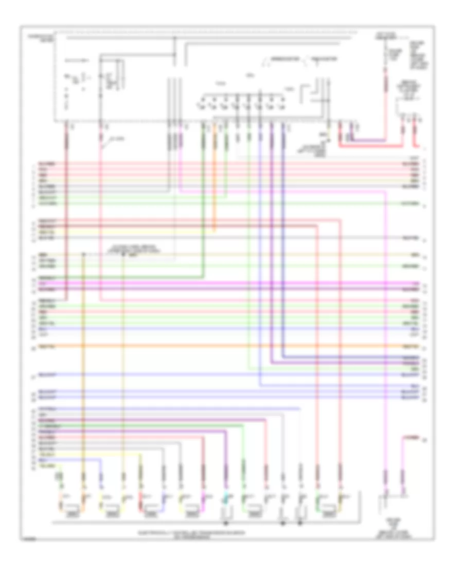
4.0L
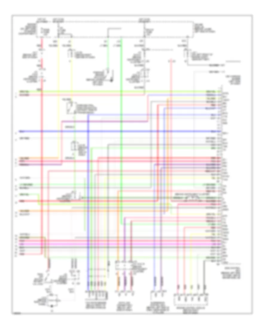
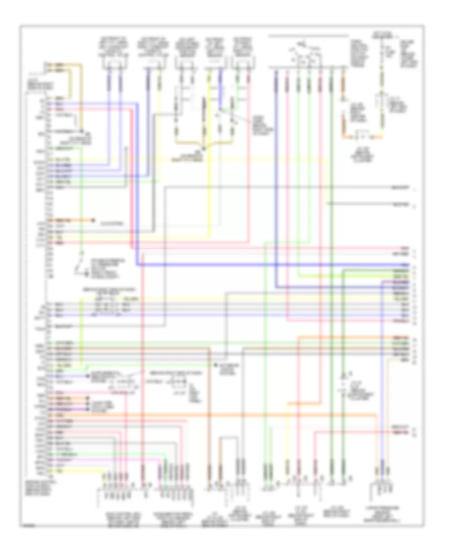
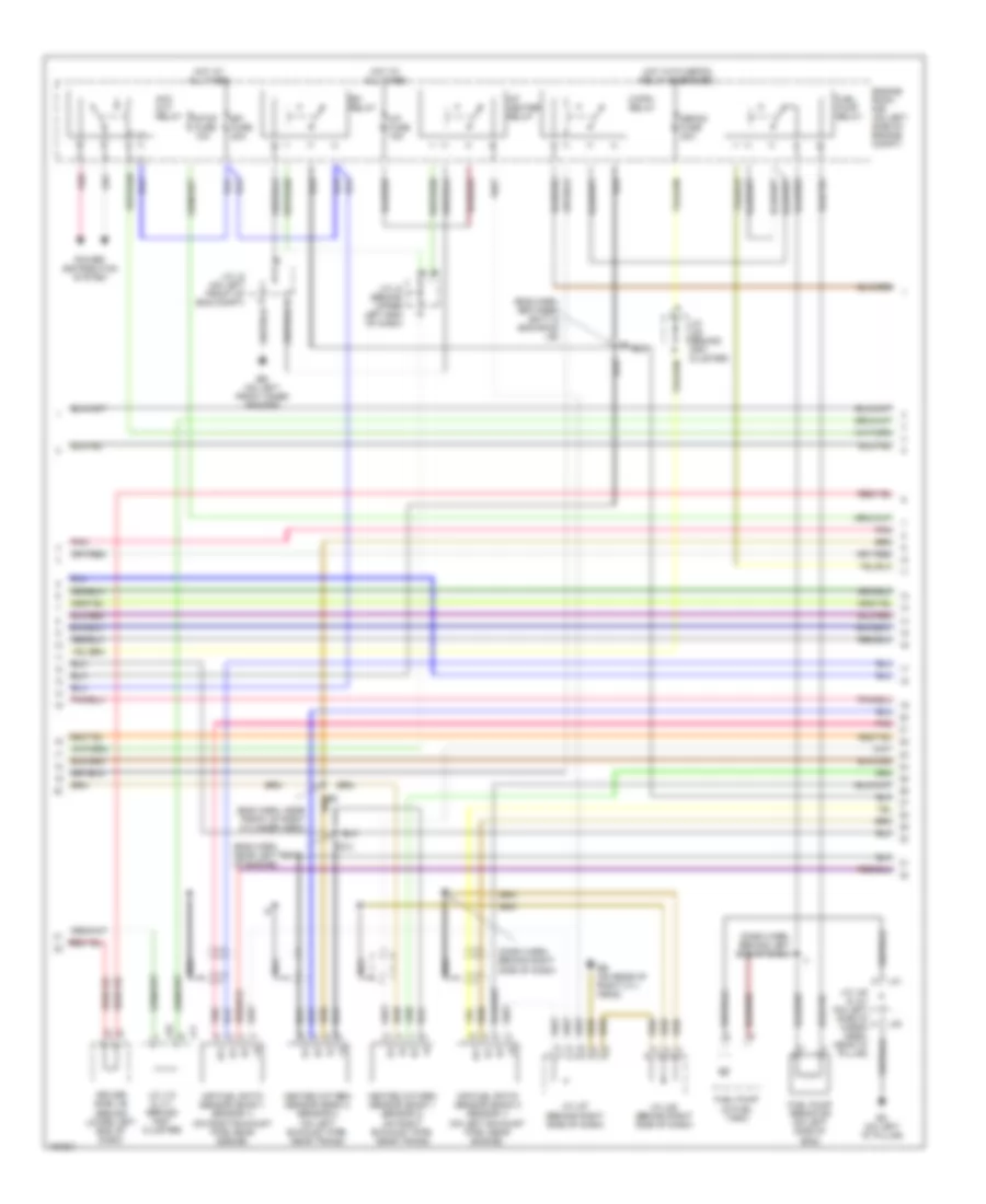
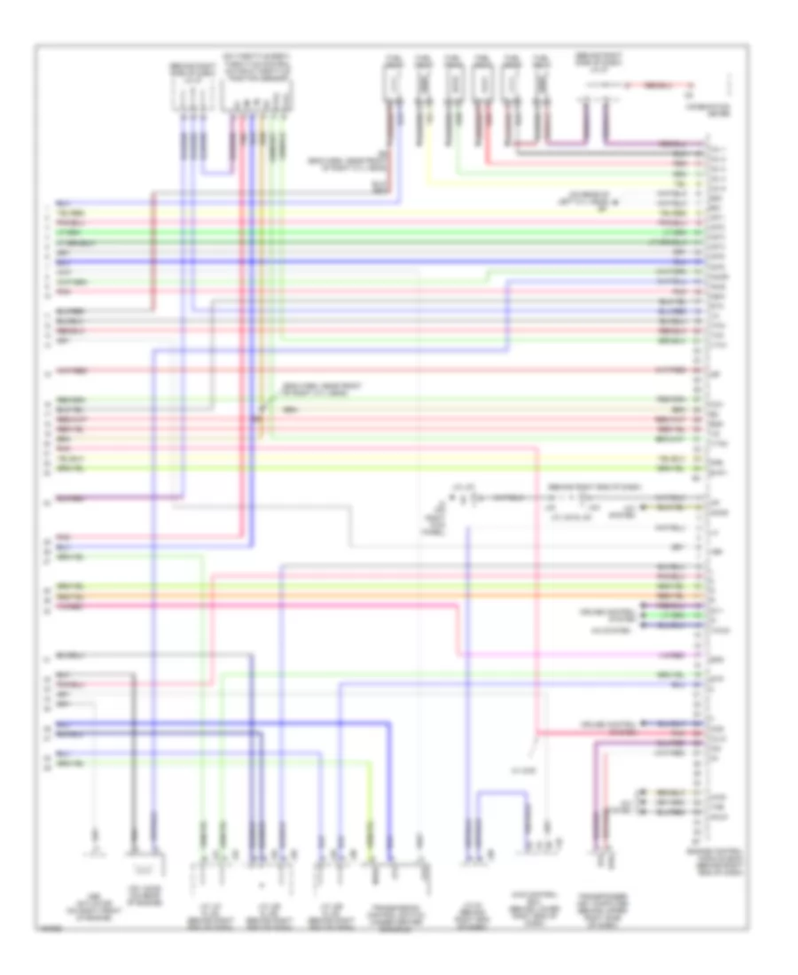
4.0L, Engine Performance Wiring Diagram (1 of 6) for Toyota 4Runner SR5 2004
 https://portal-diagnostov.com/license.html
Automotive Electricians Portal FZCO
Automotive Electricians Portal FZCO
https://portal-diagnostov.com/license.html
https://portal-diagnostov.com/license.html
Automotive Electricians Portal FZCO
Automotive Electricians Portal FZCOList of elements for 4.0L, Engine Performance Wiring Diagram (1 of 6) for Toyota 4Runner SR5 2004:
- (behind right end of dash)
- (behind right end of dash) j/c j31 & j32
- (dash harn, behind right side of dash)
- (on front of left cyl head) left camshaft timing oil control valve
- (on front of left cyl head) left vvt sensor
- (on front of right cyl head) right camshaft timing oil control valve
- (on front of right cyl head) right vvt sensor
- (on left side of eng) crankshaft position sensor
- (on rear of right cyl head)
- +b1
- A/c system
- Accelerator pedal position sensor (behind left side of dash)
- Batt
- Cluster)
- Computer data lines system
- Driver side j/b (behind lower left end of dash)
- E03
- Ee (on rear of right cyl head)
- Els
- Eng+
- Eng-
- Engine control module (ecm) (behind right end of dash)
- Eom
- Ep1
- Ep2
- Epa
- Epa2
- Exterior lights system
- F/ps
- Ge01
- Gnd
- Hot in on and start
- Ig1 fuse 15a
- Igsw
- Ik (on right kick panel)
- J/c 27 (behind right side of dash)
- J/c j20 (behind instrument cluster)
- J/c j25 (behind right center of dash)
- J/c j29 (behind right end of dash)
- J/c j31 & j32 (behind right end of dash)
- J/c j33 & j34
- J/c j33 & j34 (behind right end of dash)
- J/c j35 (behind right end of dash)
- J/c j37
- J/c j7 (behind left end of dash)
- J/c j8 & j9 (behind instrument j8
- J/c j8 (behind instrument cluster)
- J29
- J31
- J32
- J33
- J34
- J35
- Lcki
- Me01
- Mrel
- Nca
- Ne+
- Ne-
- Neo
- Oc1+
- Oc1-
- Oc2+
- Oc2-
- Park/ neutral position switch (on right side of trans)
- Pnk
- Power steering oil pressure switch (right front of eng compt)
- Psw
- Ptnk
- Red
- Sil
- Skid control ecu (behind left end of dash, above driver side j/b)
- Sp1
- Stsw
- Tach
- Trc+
- Trc-
- Vapor pressure sensor (near left rear fenderwell)
- Vcc
- Vcp1
- Vcp2
- Vcpa
- Vpa
- Vpa1
- Vpa2
- Vv1+
- Vv2+
- Wfse
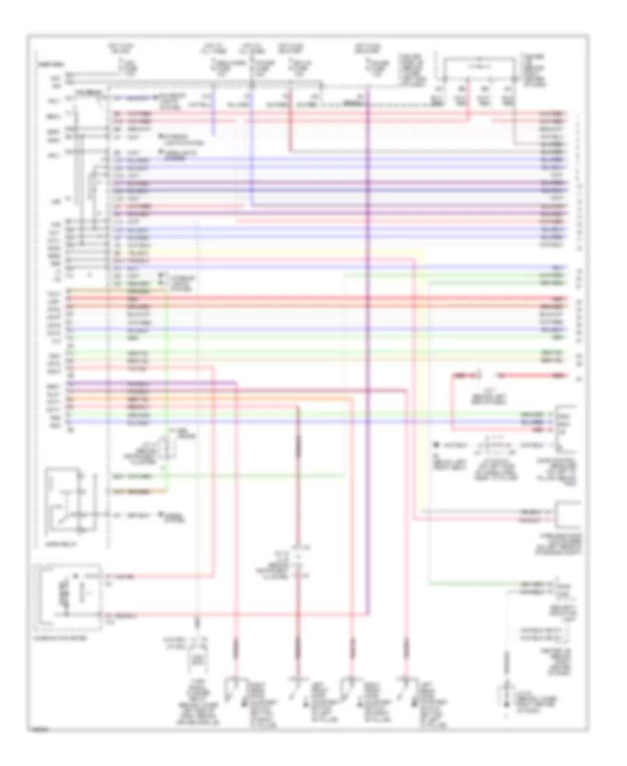
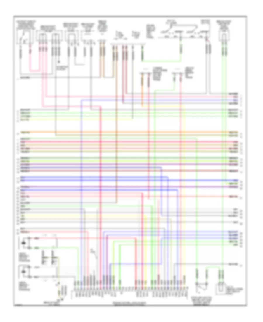
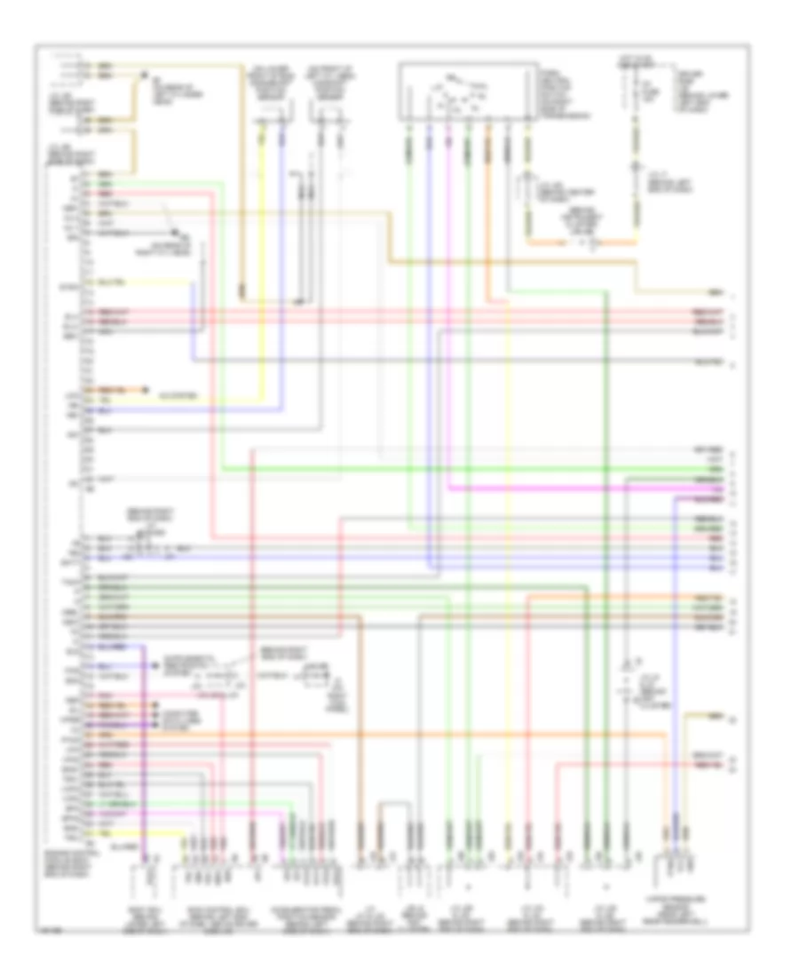
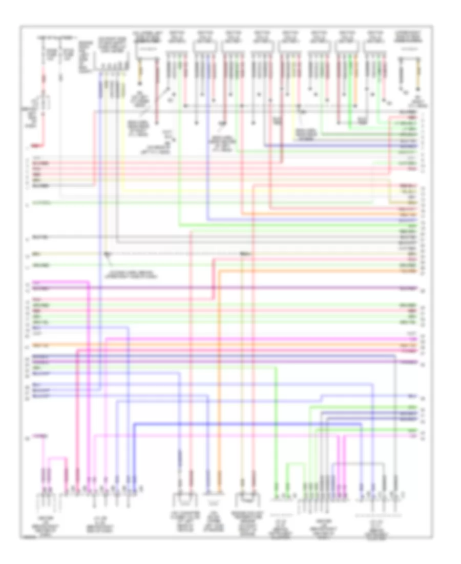
4.0L, Engine Performance Wiring Diagram (2 of 6) for Toyota 4Runner SR5 2004
 https://portal-diagnostov.com/license.html
Automotive Electricians Portal FZCO
Automotive Electricians Portal FZCO
https://portal-diagnostov.com/license.html
https://portal-diagnostov.com/license.html
Automotive Electricians Portal FZCO
Automotive Electricians Portal FZCOList of elements for 4.0L, Engine Performance Wiring Diagram (2 of 6) for Toyota 4Runner SR5 2004:
- (dash harn, behind left end of dash)
- (dash harn, behind right side of dash)
- (eng harn, between batt & eng room j/b)
- (eng harn, near front of right cylinder head)
- (eng harn, near left rear of engine)
- A/f fuse 15a
- A/f heater relay
- Acc cut relay
- Af+
- Af-
- Air fuel ratio sensor (bank 1 sensor 1) (on right exhaust pipe, near engine)
- Air fuel ratio sensor (bank 2 sensor 1) (on left exhaust pipe, near engine)
- Bo (on left "d" pillar)
- C/opn relay
- Defog fuse 30a
- Driver side j/b (behind lower left end of dash)
- E13
- Eb (on left front inner fender)
- Ee (on rear of right cyl head)
- Efi fuse 20a
- Efi relay
- Engine room r/b (on left side of engine compt)
- Fuel pump (in fuel tank)
- Fuel pump relay
- Fuel pump resistor (on left side of eng)
- Heated oxygen sensor (bank 1 sensor 2) (on right exhaust pipe, near trans)
- Heated oxygen sensor (bank 2 sensor 2) (on left exhaust pipe, near trans)
- Hot at all times
- Hot with defog relay energized
- J/c j10 & j11 (behind inst cluster)
- J/c j2 (on left front of eng compt)
- J/c j22 (behind inst cluster)
- J/c j27 (behind right side of dash)
- J/c j28 (behind right side of dash)
- J/c j4 (behind upper left end of dash)
- J/c j40 & j41 (on left side of cargo area, near "d" pillar)
- J10
- J11
- J40
- J41
- Nca
- Pnk
- Power distribution system
- Stop fuse 10a
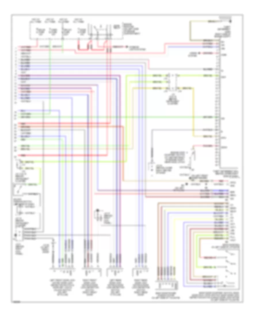
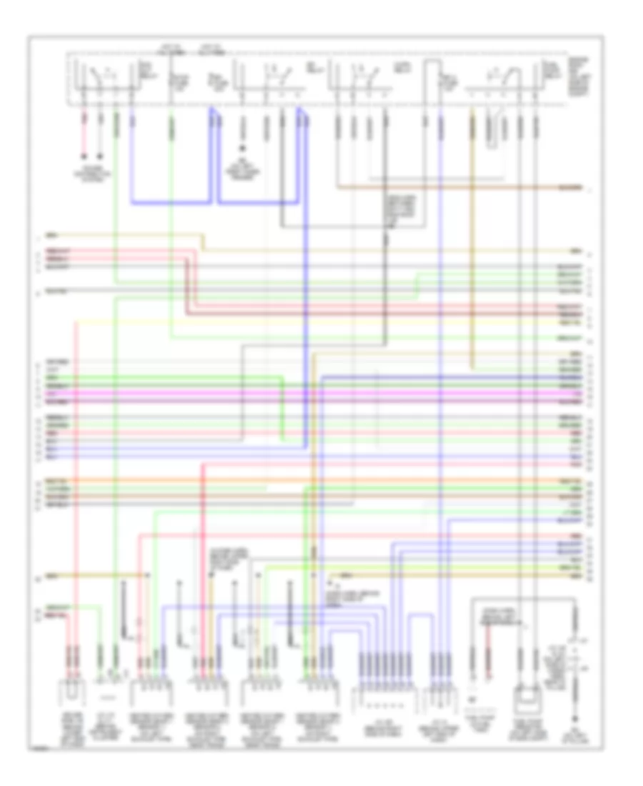
4.0L, Engine Performance Wiring Diagram (3 of 6) for Toyota 4Runner SR5 2004
 https://portal-diagnostov.com/license.html
Automotive Electricians Portal FZCO
Automotive Electricians Portal FZCO
https://portal-diagnostov.com/license.html
https://portal-diagnostov.com/license.html
Automotive Electricians Portal FZCO
Automotive Electricians Portal FZCOList of elements for 4.0L, Engine Performance Wiring Diagram (3 of 6) for Toyota 4Runner SR5 2004:
- (behind inst cluster) j/c j8 & j9
- (behind right center of dash) center j/b
- (behind right end of dash) j/c j31 & j32
- (behind right side of dash) j/c j28
- (behind upper left end of dash) j/c j4
- (on right side of transmission) park/neutral position switch
- 4wd
- Acc
- Afl+
- Afl-
- Afr+
- Afr-
- Driver side j/b (behind left kick panel)
- E05
- E06
- E10
- E11
- E23
- Ee (rear of right cyl head)
- Ekn2
- Eknk
- Engine control module (ecm) (behind right end of dash)
- Hafl
- Hafr
- Hot at all times
- Ht1b
- Ht2b
- Ign fuse 10a
- Ignition switch
- Inj 6
- J/c j4 (behind upper left end of dash)
- J11
- J31
- J32
- Knk1
- Knk2
- Knock sensor 1 (on top of engine)
- Knock sensor 2 (on top of engine)
- Lock
- Nca
- Nco+
- Nco-
- Ox1b
- Ox2b
- P/n
- Pnk
- Red
- Slt+
- Slt-
- Sp2+
- Sp2-
- Sta 2 fuse 7.5a
- Star
- Start
- Starting system
- Stoplight switch (behind left side of dash, above brake pedal)
- Th0c
- Turbine shaft speed sensor (on left side of trans)
- Vehicle speed sensor (on trans)
- W/ 4wd
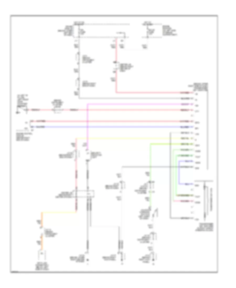
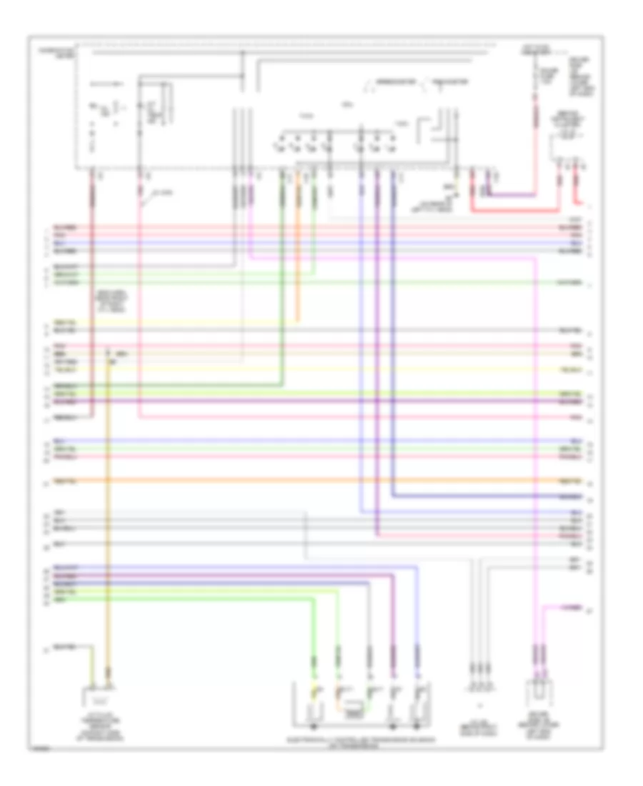
4.0L, Engine Performance Wiring Diagram (4 of 6) for Toyota 4Runner SR5 2004
 https://portal-diagnostov.com/license.html
Automotive Electricians Portal FZCO
Automotive Electricians Portal FZCO
https://portal-diagnostov.com/license.html
https://portal-diagnostov.com/license.html
Automotive Electricians Portal FZCO
Automotive Electricians Portal FZCOList of elements for 4.0L, Engine Performance Wiring Diagram (4 of 6) for Toyota 4Runner SR5 2004:
- (behind instrument cluster) j/c j8 & j9
- (eng harn, near front of right cyl head)
- (on transmission)
- A/t fluid temperature sensor (on right side of transmission)
- A/t oil temp ind
- C10
- C11
- Combination meter
- Cpu
- Driver side j/b (behind lower left end of dash)
- Ef (on rear of left cyl head)
- Electronically controlled transmission solenoid
- Gauge fuse 7.5a
- Hot in on and start
- J/c j28 (behind right side of dash)
- K11
- Mil ind
- Pnk
- Red
- Red/
- Slt+
- Slt-
- Speedometer
- Tachometer
- W/ 4wd
4.0L, Engine Performance Wiring Diagram (5 of 6) for Toyota 4Runner SR5 2004
 https://portal-diagnostov.com/license.html
Automotive Electricians Portal FZCO
Automotive Electricians Portal FZCO
https://portal-diagnostov.com/license.html
https://portal-diagnostov.com/license.html
Automotive Electricians Portal FZCO
Automotive Electricians Portal FZCOList of elements for 4.0L, Engine Performance Wiring Diagram (5 of 6) for Toyota 4Runner SR5 2004:
- (at rear of engine) noise filter 1
- (engine harn, near front of right cylinder head)
- (engine harn, near left rear of eng)
- (on right side of eng compt, on air intake) mass airflow (maf) meter
- Center j/b (behind right center of dash)
- Dome fuse 10a
- Driver side j/b (behind lower left end of dash)
- E12
- E13
- E2g
- E5 (eng harn, near center of left cyl head)
- E9 (in eng harn, near front of right cyl head)
- Ef (on rear of left cylinder head)
- Engine coolant temperature sensor (upper left side of engine)
- Engine room r/b (on left side of eng compt)
- Etcs fuse 10a
- Hot at all times
- Ignition coil & igniter 1
- Ignition coil & igniter 2
- Ignition coil & igniter 3
- Ignition coil & igniter 4
- Ignition coil & igniter 5
- Ignition coil & igniter 6
- J/c j10 & j11 (behind instrument cluster)
- J/c j29 & 30 (behind right end of dash)
- J/c j7 (behind left end of dash)
- J10
- J11
- J29
- J30
- Pnk
- Red
- Tha
- Vsv (canister closed valve) (at left rear of vehicle)
- Vsv (evap) (upper left side of engine)
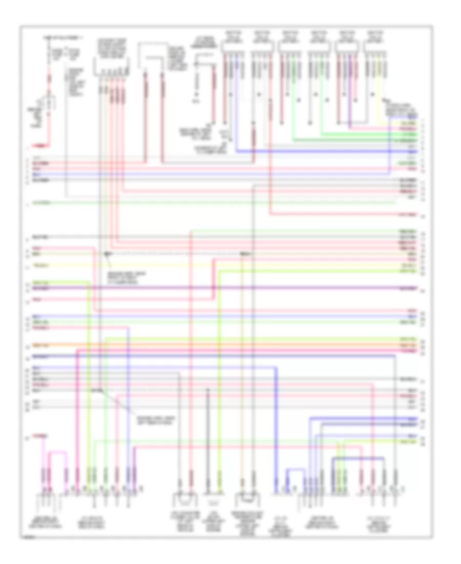
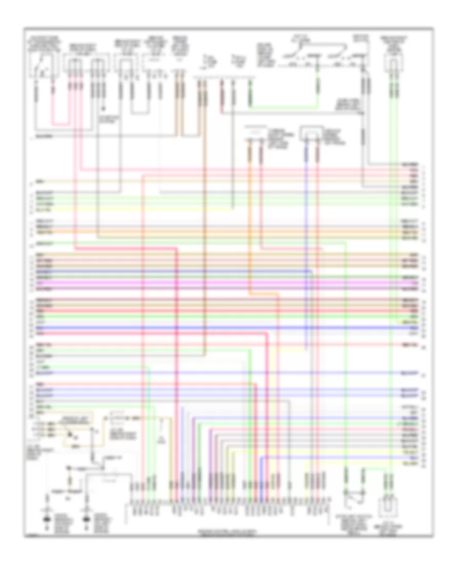
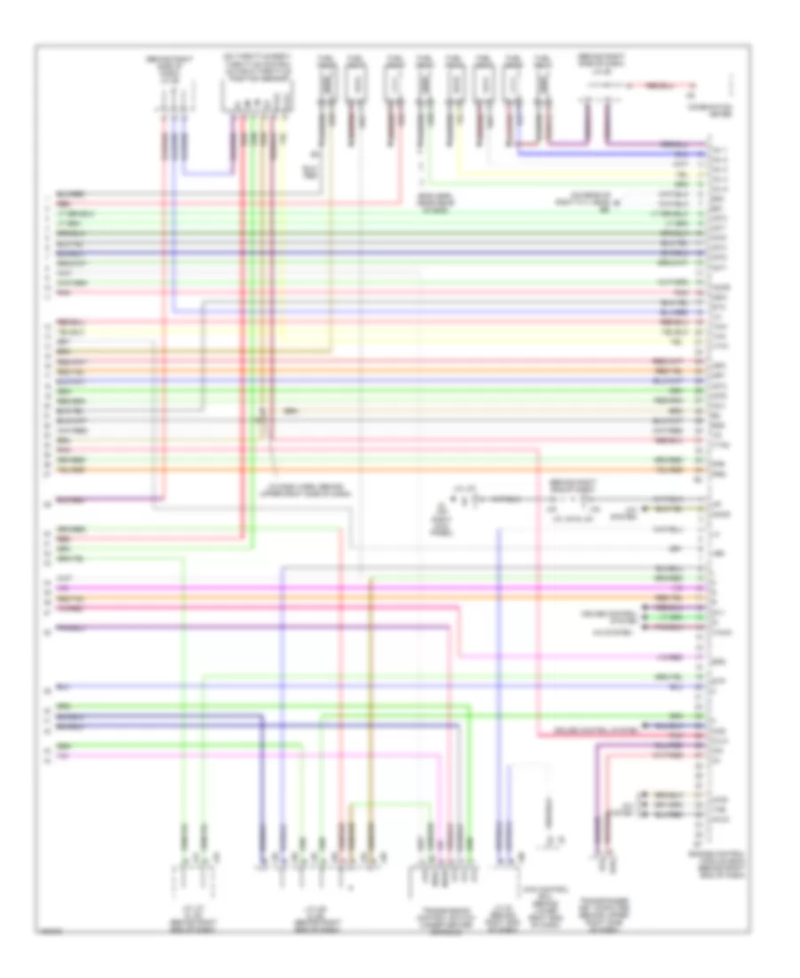
4.0L, Engine Performance Wiring Diagram (6 of 6) for Toyota 4Runner SR5 2004
 https://portal-diagnostov.com/license.html
Automotive Electricians Portal FZCO
Automotive Electricians Portal FZCO
https://portal-diagnostov.com/license.html
https://portal-diagnostov.com/license.html
Automotive Electricians Portal FZCO
Automotive Electricians Portal FZCOList of elements for 4.0L, Engine Performance Wiring Diagram (6 of 6) for Toyota 4Runner SR5 2004:
- (behind right end of dash)
- (behind right side of dash) j/c 27
- (eng harn, near front of right cyl head)
- (on rear of left cyl head)
- (on throttle body) throttle control motor & throttle position sensor
- +bm
- 4wd control ecu (behind lower right end of dash)
- A/c system
- A/cs
- Accr
- Acis
- Acld
- Acmg
- Add actuator (on right front of engine)
- At3
- Atd
- Ccs
- Ccv
- Combination meter
- Cruise control system
- E01
- E02
- E2g
- E8 (eng harn, near front of right cyl head)
- Efii
- Efio
- Engine control module (ecm) (behind right end of dash)
- Evp1
- F10
- Fpr
- Fuel inj 1
- Fuel inj 2
- Fuel inj 3
- Fuel inj 4
- Fuel inj 5
- Fuel inj 6
- Igf
- Igt1
- Igt2
- Igt3
- Igt4
- Igt5
- Igt6
- Ik (on right kick panel)
- Imi
- Imo
- Inj 1
- Inj 2
- Inj 3
- Inj 4
- Inj 5
- J/c 30 (behind right end of dash)
- J/c j29 & j30 (behind right end of dash)
- J/c j31 & j32 (behind right end of dash)
- J/c j33 & j34
- J/c j35 & j36 (behind right end of dash)
- J/c j37
- J29
- J30
- J31
- J32
- J33
- J35
- J36
- J3a
- Nssd
- Nsw
- Oilw
- Pnk
- Red
- Spd
- St1
- Sta
- Stp
- Tha
- The
- Thw
- Thwo
- Transmission control switch (under center console)
- Transponder key computer (behind upper right side of dash)
- Vsv (acis) (on rear of engine)
- Vta1
- Vta2
- W/ 4wd
4.7L
4.7L, Engine Performance Wiring Diagram (1 of 6) for Toyota 4Runner SR5 2004
 https://portal-diagnostov.com/license.html
Automotive Electricians Portal FZCO
Automotive Electricians Portal FZCO
https://portal-diagnostov.com/license.html
https://portal-diagnostov.com/license.html
Automotive Electricians Portal FZCO
Automotive Electricians Portal FZCOList of elements for 4.7L, Engine Performance Wiring Diagram (1 of 6) for Toyota 4Runner SR5 2004:
- (behind instrument cluster) j/c j20
- (behind right end of dash)
- (behind right end of dash) j/c j31 & j32
- (on front of left cyl head) camshaft position sensor
- (on lower front of eng) crankshaft position sensor
- (on rear of right cyl head)
- +b2
- A/c system
- Accelerator pedal position sensor (behind left side of dash)
- Batt
- Body ecu (behind lower left end of dash)
- Cluster)
- Computer data lines system
- Driver side j/b (behind lower left end of dash)
- E03
- Ef (on rear of left cylinder head)
- Els
- Els1
- Eng+
- Eng-
- Engine control module (ecm) (behind right end of dash)
- Eom
- Ep1
- Ep2
- Epa
- Epa2
- F/ps
- G2+
- G2-
- Ge01
- Gnd
- Hot in on and start
- Ig1 fuse 15a
- Igsw
- Ik (on right kick panel)
- Inj 7
- Inj 8
- J/b j8 (behind inst cluster)
- J/c j25 (behind center of dash)
- J/c j26 (behind right side of dash)
- J/c j28 (behind right side of dash)
- J/c j29 & j30 (behind right end of dash)
- J/c j31 & j32 (behind right end of dash)
- J/c j33 & j34
- J/c j33 & j34 (behind right end of dash)
- J/c j35 & j36 (behind right end of dash)
- J/c j37
- J/c j7 (behind left end of dash)
- J/c j8 & j9 (behind inst j8
- J29
- J30
- J31
- J32
- J33
- J34
- J35
- J36
- Lcki
- Me01
- Mrel
- Nca
- Ne+
- Ne-
- Neo
- Park/ neutral position switch (on right side of transmission)
- Pnk
- Ptnk
- Red
- Sil
- Skid control ecu (behind left end of dash, above driver side j/b)
- Slu+
- Slu-
- Sp1
- Stsw
- Tach
- Trc+
- Trc-
- Vapor pressure sensor (near left rear fenderwell)
- Vcc
- Vcp1
- Vcp2
- Vcpa
- Vpa
- Vpa1
- Vpa2
- Wfse
4.7L, Engine Performance Wiring Diagram (2 of 6) for Toyota 4Runner SR5 2004
 https://portal-diagnostov.com/license.html
Automotive Electricians Portal FZCO
Automotive Electricians Portal FZCO
https://portal-diagnostov.com/license.html
https://portal-diagnostov.com/license.html
Automotive Electricians Portal FZCO
Automotive Electricians Portal FZCOList of elements for 4.7L, Engine Performance Wiring Diagram (2 of 6) for Toyota 4Runner SR5 2004:
- (dash harn, behind left end of dash)
- (dash harn, behind right side of dash)
- (eng harn, between batt and eng room j/b) e6
- (in dash harn, behind upper right side of dash) i8
- Acc cut relay
- Bo (on left "d" pillar)
- C/opn relay
- Driver side j/b (behind lower left end of dash)
- Eb (on left front inner fender)
- Efi 2 fuse 10a
- Efi fuse 20a
- Efi relay
- Engine room r/b (on left side of engine compt)
- Fuel pump (in fuel tank)
- Fuel pump relay
- Fuel pump resistor (on left side of eng compt)
- Heated oxygen sensor (bank 1 sensor 1) (on left exhaust pipe)
- Heated oxygen sensor (bank 1 sensor 2) (on left exhaust pipe, near trans)
- Heated oxygen sensor (bank 2 sensor 1) (on right exhaust pipe)
- Heated oxygen sensor (bank 2 sensor 2) (on right exhaust pipe, near trans)
- Hot at all times
- J/c j10 & j11 (behind instrument cluster)
- J/c j28 (behind right side of dash)
- J/c j4 (behind upper left end of dash)
- J/c j40 & j41 (on left side of cargo area, near "d" pillar)
- J10
- J11
- J40
- J41
- Nca
- Pnk
- Power distribution system
- Red
- Stop fuse 10a
4.7L, Engine Performance Wiring Diagram (3 of 6) for Toyota 4Runner SR5 2004
 https://portal-diagnostov.com/license.html
Automotive Electricians Portal FZCO
Automotive Electricians Portal FZCO
https://portal-diagnostov.com/license.html
https://portal-diagnostov.com/license.html
Automotive Electricians Portal FZCO
Automotive Electricians Portal FZCOList of elements for 4.7L, Engine Performance Wiring Diagram (3 of 6) for Toyota 4Runner SR5 2004:
- (behind instrument cluster) j/c j8 & j9
- (behind right center of dash) center j/b
- (behind right end of dash) j/c j31 & j32
- (behind right side of dash) j/c j28
- (behind upper left end of dash) j/c j4
- (dash harn, behind left end of dash) i2
- (on right side of transmission) park/neutral position switch
- (rear of left cylinder head)
- 4wd
- Acc
- Driver side j/b (behind lower left end of dash)
- E23
- Engine control module (ecm) (behind right end of dash)
- Hot at all times
- Ht1a
- Ht1b
- Ht2a
- Ht2b
- Ign fuse 10a
- Ignition switch
- Inj 6
- J/c j26 (behind right side of dash)
- J/c j28 (behind right side of dash)
- J/c j4 (behind upper left end of dash)
- J11
- J31
- J32
- Knk1
- Knk2
- Knock sensor 1 (on left side of engine)
- Knock sensor 2 (on right side of engine)
- Lock
- Nca
- Nt+
- Nt-
- Ox1a
- Ox1b
- Ox2a
- Ox2b
- P/n
- Pnk
- Red
- Sl1+
- Sl1-
- Sl2+
- Sl2-
- Slt+
- Slt-
- Sp2+
- Sp2-
- Sta 2 fuse 7.5a
- Star
- Start
- Starting system
- Stoplight switch (behind left side of dash, above brake pedal)
- Th01
- Th02
- Turbine shaft speed sensor (left side of trans)
- Vehicle speed sensor (on trans)
- W/ 4wd
4.7L, Engine Performance Wiring Diagram (4 of 6) for Toyota 4Runner SR5 2004
 https://portal-diagnostov.com/license.html
Automotive Electricians Portal FZCO
Automotive Electricians Portal FZCO
https://portal-diagnostov.com/license.html
https://portal-diagnostov.com/license.html
Automotive Electricians Portal FZCO
Automotive Electricians Portal FZCOList of elements for 4.7L, Engine Performance Wiring Diagram (4 of 6) for Toyota 4Runner SR5 2004:
- (behind instrument cluster) j/c j8 & j9
- (in dash harn, behind upper right side of dash)
- A/t oil temp ind
- C10
- C11
- Combination meter
- Cpu
- Driver side j/b (behind lower left end of dash)
- Ef (on rear of left cylinder head)
- Electronically controlled transmission solenoid (on transmission)
- Gauge fuse 7.5a
- Hot in on and start
- K11
- Mil ind
- Ot+
- Ot-
- Ot2+
- Ot2-
- Pnk
- Red
- Red/
- Sl1+
- Sl1-
- Sl2+
- Sl2-
- Slt+
- Slt-
- Slu+
- Slu-
- Speedometer
- Tachometer
- W/ 4wd
4.7L, Engine Performance Wiring Diagram (5 of 6) for Toyota 4Runner SR5 2004
 https://portal-diagnostov.com/license.html
Automotive Electricians Portal FZCO
Automotive Electricians Portal FZCO
https://portal-diagnostov.com/license.html
https://portal-diagnostov.com/license.html
Automotive Electricians Portal FZCO
Automotive Electricians Portal FZCOList of elements for 4.7L, Engine Performance Wiring Diagram (5 of 6) for Toyota 4Runner SR5 2004:
- (eng harn, near center of left cyl head)
- (eng harn, near rear of eng)
- (eng harn, near rear of right cyl head)
- (in dash harn, behind upper right side of dash)
- (on right side of eng compt) mass airflow (maf) meter
- (on upper left side of eng) noise filter 1
- (upper right side of eng) noise filter 2
- Center j/b (behind right center of dash)
- Dome fuse 10a
- E2g
- Ec (right cyl head)
- Ed (on left cylinder head)
- Ee (on rear of left cyl head)
- Engine coolant temperature sensor (on right front of engine)
- Engine room r/b (left side of eng compt)
- Etcs fuse 10a
- Hot at all times
- Ignition coil & igniter 1
- Ignition coil & igniter 2
- Ignition coil & igniter 3
- Ignition coil & igniter 4
- Ignition coil & igniter 5
- Ignition coil & igniter 6
- Ignition coil & igniter 7
- Ignition coil & igniter 8
- J/c j10 & j11 (behind instrument cluster)
- J/c j29 & j30 (behind right end of dash)
- J/c j7 (behind left end of dash)
- J/c j8 & j9 (behind instrument cluster)
- J10
- J11
- J29
- J30
- Pnk
- Red
- Tha
- Vsv (canister closed valve) (at left rear of vehicle)
- Vsv (evap) (upper left side of engine)
4.7L, Engine Performance Wiring Diagram (6 of 6) for Toyota 4Runner SR5 2004
 https://portal-diagnostov.com/license.html
Automotive Electricians Portal FZCO
Automotive Electricians Portal FZCO
https://portal-diagnostov.com/license.html
https://portal-diagnostov.com/license.html
Automotive Electricians Portal FZCO
Automotive Electricians Portal FZCOList of elements for 4.7L, Engine Performance Wiring Diagram (6 of 6) for Toyota 4Runner SR5 2004:
- (behind right end of dash)
- (behind right side of dash) j/c 26
- (eng harn, near rear of eng)
- (in dash harn, behind upper right side of dash)
- (on rear of right cyl head)
- (on throttle body) throttle control motor & throttle position sensor
- +bm
- 4wd control ecu (behind lower right end of dash)
- A/c system
- A/cs
- Accr
- Acld
- Acmg
- At2
- At4
- Atd
- Atl
- Ccs
- Ccv
- Combination meter
- Cruise control system
- E01
- E02
- E2g
- Efii
- Efio
- Engine control module (ecm) (behind right end of dash)
- Fpr
- Fuel inj 1
- Fuel inj 2
- Fuel inj 3
- Fuel inj 4
- Fuel inj 5
- Fuel inj 6
- Fuel inj 7
- Fuel inj 8
- Igf1
- Igf2
- Igt1
- Igt2
- Igt3
- Igt4
- Igt5
- Igt6
- Igt7
- Igt8
- Ik (on right kick panel)
- Imi
- Imo
- Inj 1
- Inj 2
- Inj 3
- Inj 4
- Inj 5
- J/c 30 (behind right end of dash)
- J/c j31 & j32 (behind right end of dash)
- J/c j33 & j34
- J/c j35 & j36 (behind right end of dash)
- J/c j37
- J30
- J31
- J32
- J33
- J34
- J35
- J36
- Nssd
- Nssl
- Nsw
- Oilw
- Pnk
- Prg
- Red
- Spd
- St1
- Sta
- Stp
- Tha
- The
- Thw
- Thwo
- Transmission control switch (under center console)
- Transponder key computer (behind upper right side of dash)
- Vta1
- Vta2
EXTERIOR LIGHTS
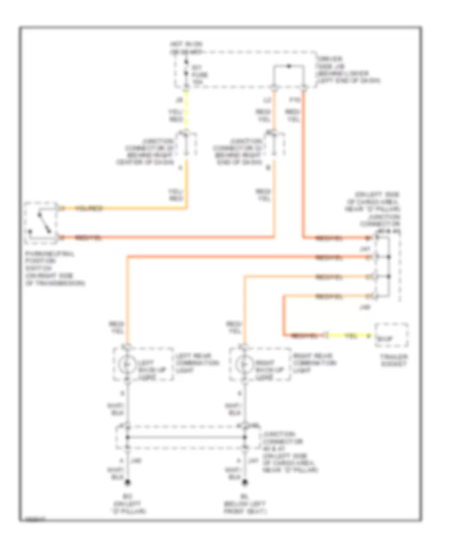
Back-up Lamps Wiring Diagram for Toyota 4Runner SR5 2004
 https://portal-diagnostov.com/license.html
Automotive Electricians Portal FZCO
Automotive Electricians Portal FZCO
https://portal-diagnostov.com/license.html
https://portal-diagnostov.com/license.html
Automotive Electricians Portal FZCO
Automotive Electricians Portal FZCOList of elements for Back-up Lamps Wiring Diagram for Toyota 4Runner SR5 2004:
- (on left side of cargo area, near ``d" pillar) junction connector 40 & 41
- A j40
- A j41
- B/up
- Bl (below left front seat)
- Bo (on left ``d" pillar)
- Driver side j/b (behind lower left end of dash)
- F10
- Hot in on
- Ig1 fuse 15a
- J40
- J41
- Junction connector 25 (behind right center of dash)
- Junction connector 33 (behind right end of dash)
- Junction connector 40 & 41 (on left side of cargo area, near ``d" pillar)
- Left back-up light
- Left rear combination light
- Or start
- Park/neutral position switch (on right side of transmission)
- Right back-up light
- Right rear combination light
- Trailer socket
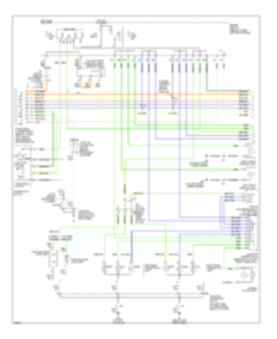
Exterior Lamps Wiring Diagram (1 of 2) for Toyota 4Runner SR5 2004
 https://portal-diagnostov.com/license.html
Automotive Electricians Portal FZCO
Automotive Electricians Portal FZCO
https://portal-diagnostov.com/license.html
https://portal-diagnostov.com/license.html
Automotive Electricians Portal FZCO
Automotive Electricians Portal FZCOList of elements for Exterior Lamps Wiring Diagram (1 of 2) for Toyota 4Runner SR5 2004:
- (behind lower left end of dash, behind driver side j/b)
- (in dash harness, above driver
- (near front of left rear wheelwell)
- (on left front of engine compt, near battery) j/c 1
- 4.7l
- A j40
- B11
- Bl (below left front seat)
- Bo (on left ``d" pillar)
- Body ecu
- Combination switch
- Driver side j/b (behind lower left end of dash)
- E20
- E24
- Ea (on right front inner fender)
- Eb (on left front inner fender)
- F13
- F15
- F16
- Haz
- Head
- High mounted stoplight
- Hot at all times
- Hot in on or start
- Idl
- Ig1 fuse 15a
- J/c 15 (behind instrument cluster)
- J/c 20 & 21 (behind instrument cluster)
- J/c 40 & 41 (on left side of j40 cargo area, near "d" pillar)
- J12
- J14
- J15
- J20
- J21 f
- J22 e
- J23
- J23 d
- J41
- J41 a
- Junction connector 22 & 23 (behind instrument cluster)
- Junction connector 39
- Junction connector 40 & 41 (on left side of cargo area, near ``d" pillar)
- Junction connector 5 (behind right kick panel)
- Left
- Left front parking light
- Left rear combination light
- License plate light
- Light ctrl switch
- Ltin
- Off
- Right
- Right front parking light
- Right rear combination light
- Rtin
- Side j/b)
- Sltin
- Stop
- Stp1
- Tail
- Tail fuse 10a
- Tail relay
- Tfl
- Tfr
- Towing converter relay (on left side of cargo area)
- Trl
- Trly
- Trr
- Tsl
- Tsr
- Turn
- Turn signal flasher relay
- Turn signal switch
- W/ drl
- W/ rear spoiler
- W/o drl
- W/o rear spoiler
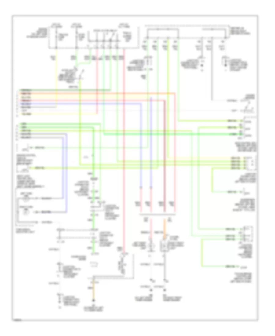
Exterior Lamps Wiring Diagram (2 of 2) for Toyota 4Runner SR5 2004
 https://portal-diagnostov.com/license.html
Automotive Electricians Portal FZCO
Automotive Electricians Portal FZCO
https://portal-diagnostov.com/license.html
https://portal-diagnostov.com/license.html
Automotive Electricians Portal FZCO
Automotive Electricians Portal FZCOList of elements for Exterior Lamps Wiring Diagram (2 of 2) for Toyota 4Runner SR5 2004:
- (behind instrument cluster)
- (behind upper left end of dash)
- 4.7l
- B j16
- Base of ``a" pillar)
- C10
- Center j/b (behind right center of dash)
- Combination meter
- Ea (on right front inner fender)
- Eb (on left front inner fender)
- Ef (on rear of left cylinder head)
- Engine control module (behind right end of dash)
- Engine room r/b (on left side of engine compt)
- Hazard switch
- Hot at all times
- J10 a
- J10 c
- J11 a
- J11 c
- J16 b
- J20 a
- J21 e
- J22
- J23
- J31 h
- J32 e
- Junction connector 10 & 11 (behind instrument cluster)
- Junction connector 15 (behind instrument cluster)
- Junction connector 16 & 17
- Junction connector 20 & 21 (behind instrument cluster)
- Junction connector 22 & 23 (behind instrument cluster)
- Junction connector 24 (behind lower right center of dash)
- Junction connector 31 & 32 (behind right end of dash)
- Junction connector 37 (behind right kick panel)
- Junction connector 4
- Junction connector 5 (behind right kick panel)
- Left front turn signal light
- Left turn ind
- Rh hi head fuse 10a
- Right front turn signal light
- Right turn ind
- S10
- Shift lever assembly)
- Shift lock control ecu (under center console, near
- Skid control ecu (behind left end of dash, above driver side j/b)
- Stop
- Stop fuse 10a
- Stop lp ctrl relay
- Stoplight switch (behind left side of dash, above brake pedal)
- Stp
- Stp2
- Stpo
- Suspension control ecu (behind left end of dash, near
- Tail ind (except usa)
- Towing brake controller (behind lower left end of dash)
- Trn-haz fuse 15a
- Turn signal indicator light
- W/ drl
- W/o drl
- W/o drl w/ drl
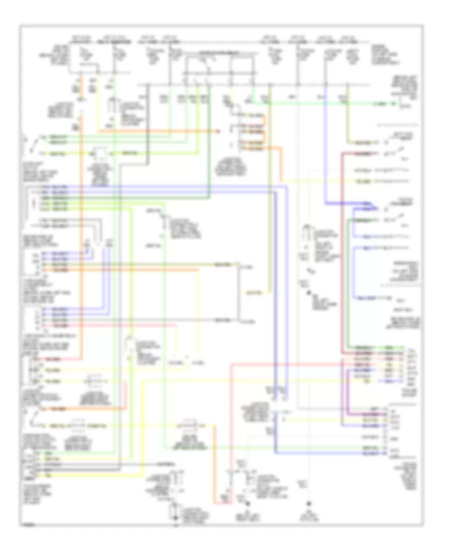
Trailer Tow Wiring Diagram for Toyota 4Runner SR5 2004
 https://portal-diagnostov.com/license.html
Automotive Electricians Portal FZCO
Automotive Electricians Portal FZCO
https://portal-diagnostov.com/license.html
https://portal-diagnostov.com/license.html
Automotive Electricians Portal FZCO
Automotive Electricians Portal FZCOList of elements for Trailer Tow Wiring Diagram for Toyota 4Runner SR5 2004:
- (behind left end of dash, above driver side j/b)
- (behind left side of dash, above brake pedal)
- B/up
- Batt
- Batt chg fuse 30a
- Batt chg relay
- Bl (below left front seat)
- Bo (on left "d" pillar)
- Body ecu
- Brk
- Driver side j/b (behind lower left end of dash)
- Drl
- E16
- E20
- E24
- Eb (on left front inner fender)
- Engine room r/b (on left side of engine compartment)
- Engine room r/b 3 (on left side of engine compartment)
- F10
- F15
- F16
- Gnd
- Hot at all times
- Hot in on or start
- Hot w/ tail relay energized
- Ig1 fuse 15a
- J12
- J14
- J15
- J20
- J21
- J23
- J40
- J41
- Junction connector (behind instrument cluster)
- Junction connector (on left front of engine compt, near battery)
- Junction connector 1 (on left front of engine compt, near battery)
- Junction connector 14 & 15 (behind instrument cluster)
- Junction connector 20 & 21 (behind instrument cluster)
- Junction connector 25 (behind right center of dash)
- Junction connector 33 (behind right end of dash)
- Junction connector 39 (near front of left rear wheelwell)
- Junction connector 4 (behind upper left end of dash)
- Junction connector 40 & 41 (on left side of j41 cargo area, near ``d" pillar)
- Junction connector 41 (on left side of cargo area, near "d" pillar)
- Junction connector 5 (behind right kick panel)
- Junction connector 7 (behind left end of dash)
- Ltin
- Ltot
- Park/neutral position switch (on right side of transmission)
- Red
- Rtin
- Rtot
- Skid control ecu
- Stin
- Stop
- Stop fuse 10a
- Stop lp ctrl relay
- Stoplight switch
- Stpo
- Sttl
- Sttr
- Tail
- Tail fuse 10a
- Towing brake controller (behind lower left end of dash)
- Towing brk fuse 30a
- Towing converter relay (on left side of cargo area)
- Towing fuse 30a
- Towing fuse 40a
- Towing tail relay
- Trailer socket
- Trl
- Trly
- Trr
- Turn signal flasher relay (w/ drl) (behind lower left end of dash, behind driver side j/b)
- Turn signal flasher relay (w/o drl) (behind lower left end of dash, behind driver side j/b)
- Turn- haz fuse 15a
- W/ drl
- W/o
- W/o drl
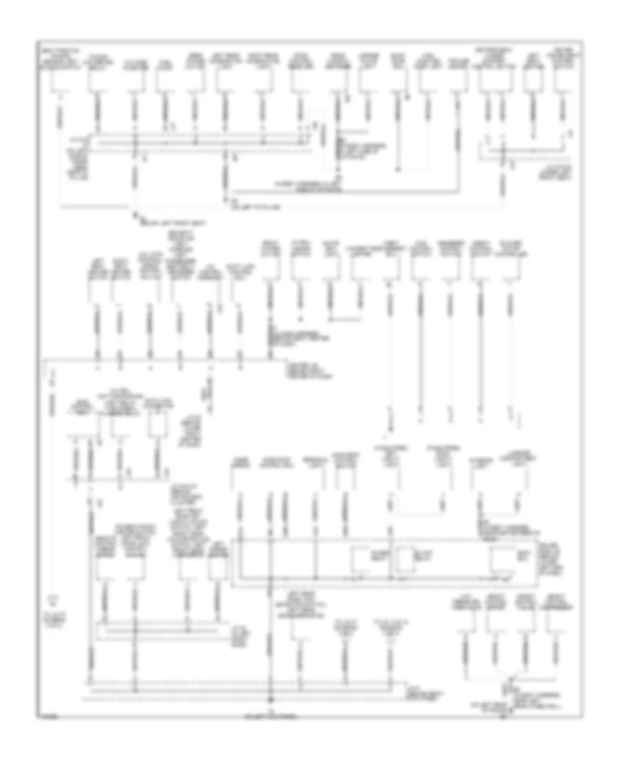
GROUND DISTRIBUTION
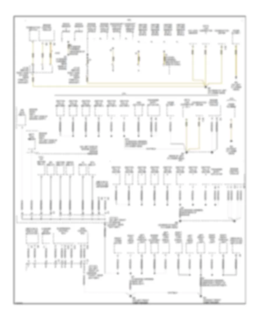
Ground Distribution Wiring Diagram (1 of 3) for Toyota 4Runner SR5 2004
 https://portal-diagnostov.com/license.html
Automotive Electricians Portal FZCO
Automotive Electricians Portal FZCO
https://portal-diagnostov.com/license.html
https://portal-diagnostov.com/license.html
Automotive Electricians Portal FZCO
Automotive Electricians Portal FZCOList of elements for Ground Distribution Wiring Diagram (1 of 3) for Toyota 4Runner SR5 2004:
- (4.0l) a/f heater relay
- (in engine harness, near rear of engine)
- (on left side of engine compt) engine room r/b
- 4.0l
- 4.7l
- 4wd
- A/c lock sensor
- Abs & ba & trac & vsc actuator
- Add actuator
- Air sus relay
- Batt chg relay
- Battery)
- C10
- Camshaft position sensor shield
- Combination meter
- Combination switch
- Compt, near battery)
- Crankshaft position sensor shield
- Data link connector
- Defog relay
- E1 (in engine harness, near right front of engine compartment)
- E12 (in engine harness, near rear of right cylinder head)
- E3 (in engine harness, near rear of engine)
- E7 (in engine harness, near left headlight)
- Ea (on right front inner fender)
- Eb (on left front inner fender)
- Ec (on right cylinder head)
- Ed (on left cylinder head)
- Ee (on rear of right cylinder head)
- Ef (on rear of left cylinder head)
- Ef (rear of left cylinder head)
- Efi relay
- Engine control module
- Engine control module shield
- Engine hood courtesy switch
- Engine room r/b 3 (on left side of engine compt)
- Engine room r/b 4 (on left side of engine compt)
- Front wiper motor
- Heated oxygen sensor (b1 s1) shield
- Heated oxygen sensor (b1 s2) shield
- Heated oxygen sensor (b2 s1) shield
- Heated oxygen sensor (b2 s2) shield
- Heater relay
- I9 (in dash harness, behind right side of dash)
- Ig relay
- Ignition coil & igniter
- Ignition coil & igniter 1
- Ignition coil & igniter 2
- Ignition coil & igniter 3
- Ignition coil & igniter 4
- Ignition coil & igniter 5
- Ignition coil & igniter 6
- J/c 2 & 3 (on left front of engine compt, near j2
- J/c 2 & 3 (on left front of engine j2
- J/c 26 (behind right side of dash, near firewall grommet)
- J/c 28 (behind right side of dash, near firewall grommet)
- Knock sensor shield
- Left front fog light
- Left front parking light
- Left front turn signal light
- Left low head- light
- Noise filter 1
- Noise filter 2
- Right front fog light
- Right front parking light
- Right front turn signal light
- Right low head- light
- S10
- S14
- S15
- Skid control ecu
- Sta relay
- Suspension control ecu
- Transfer shift actuator
- Washer level sensor
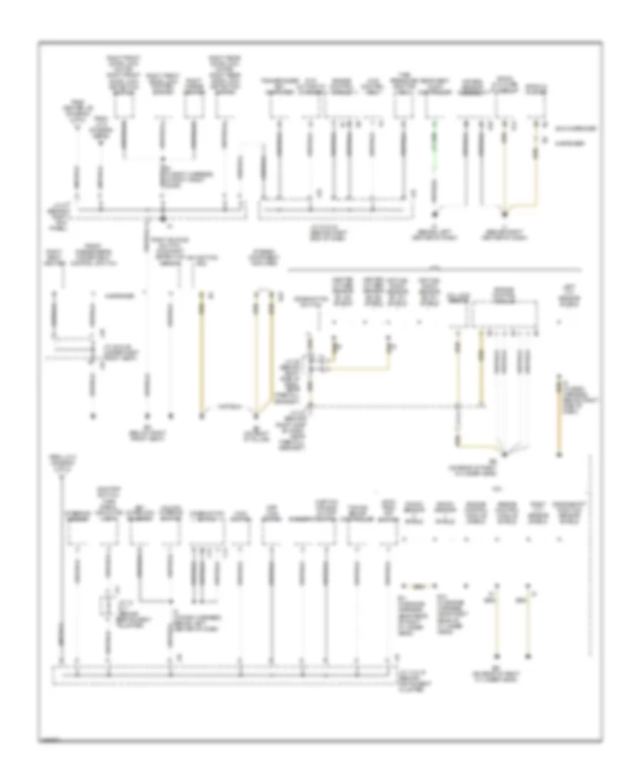
Ground Distribution Wiring Diagram (2 of 3) for Toyota 4Runner SR5 2004
 https://portal-diagnostov.com/license.html
Automotive Electricians Portal FZCO
Automotive Electricians Portal FZCO
https://portal-diagnostov.com/license.html
https://portal-diagnostov.com/license.html
Automotive Electricians Portal FZCO
Automotive Electricians Portal FZCOList of elements for Ground Distribution Wiring Diagram (2 of 3) for Toyota 4Runner SR5 2004:
- (4.0l 2wd) downhill assist control switch
- (if equipped) left vanity light
- (if equipped) right vanity light
- (on left rear of frame) bn
- (w/ drl) daytime running light relay, turn signal flasher relay
- (w/ drl) hazard switch
- 4wd control switch
- A/c control assembly
- A12
- A13
- A14
- A15
- A16
- A18
- Absorber control switch
- B3 (in body harness, near center rear of roof)
- B5 (in body harness, near left rear wheelwell)
- B6 (in body harness, in left side of liftgate)
- Back door ecu
- Bl (below left front seat)
- Blower motor controller
- Bo (on left "d" pillar)
- Body ecu
- Center j/b (behind right center of dash)
- Cigarette lighter
- Data link connector
- Dc skt relay
- Door control receiver
- Driver power seat control switch
- Driver side j/b (behind lower left end of dash)
- Driver's seat lumbar support control switch
- Front power outlet
- Fuel pump
- Glove box light
- Height control compressor
- Height control motor
- Height control switch
- Height control valve
- High mounted stop light
- I7 (in dash harness, behind right center of dash)
- Ig (on left kick panel)
- Inner mirror
- Interior light
- J/c 22 & 23 (behind instrument cluster)
- J/c 24 (behind lower right center of dash)
- J/c 38 (in left front door)
- J/c 40 & (on left side of cargo area, near "d" pillar)
- J/c 43 & 44 (under left front seat)
- J/c 5 (behind right kick panel)
- J22
- J23
- J40
- J41
- J43
- J44
- Left front door key lock & unlock switch, left front door lock detection switch, left front door lock motor
- Left mirror heater
- Left rear combination light
- Left rear door lock detection switch, left rear door lock motor
- Left seat heater
- Left seat heater switch
- License plate light
- Low pressure tank valve
- Luggage compartment light
- Moon roof control ecu
- Moon roof control switch
- Personal light
- Power relay
- Power window master switch, left front door lock control switch
- R22
- Rear power outlet
- Rear window defogger
- Remote control mirror switch
- Right rear combination light
- Right seat heater switch
- Seat position air bag sensor, left buckle switch
- Security indicator light, warning light, passenger seat belt, defogger switch
- Shift lock control ecu
- Skid control ecu
- Theft deterrent ecu
- To j/c 14 & 15 (diagram 3 of 3)
- To j/c 37 (diagram 3 of 3)
- Towing converter relay
- Trailer socket
- Voltage inverter
Ground Distribution Wiring Diagram (3 of 3) for Toyota 4Runner SR5 2004
 https://portal-diagnostov.com/license.html
Automotive Electricians Portal FZCO
Automotive Electricians Portal FZCO
https://portal-diagnostov.com/license.html
https://portal-diagnostov.com/license.html
Automotive Electricians Portal FZCO
Automotive Electricians Portal FZCOList of elements for Ground Distribution Wiring Diagram (3 of 3) for Toyota 4Runner SR5 2004:
- (4wd) trac off switch
- 4.0l
- 4wd control ecu
- 6-speaker
- A/c lock sensor
- A32
- Air bag sensor assembly
- Air fuel radio sensor (b1 s1) shield
- Air fuel radio sensor (b2 s1) shield
- B1 (in body harness, in right front door)
- Bm (below right front seat)
- Bp (on right "d" pillar)
- C12
- C14
- Combination switch
- Crankshaft position sensor shield
- Curtain air bag cutoff switch
- Diff lock switch
- Dvd automatic changer
- E10 (in engine harness, near right rear of cylinder head)
- E11 (in engine harness, near rear of right cylinder head)
- Ee (on rear of right cylinder head)
- Engine control module
- Engine control module shield
- Exc 6-speaker
- From center j/b (diagram 2 of 3)
- From j/c 5 (diagram 2 of 3)
- Front passenger's power seat control switch
- Heated oxygen sensor (b1 s2) shield
- Heated oxygen sensor (b2 s2) shield
- I5 (in dash harness, behind left center of dash)
- I9 (in dash harness, behind right side of dash)
- Ih (behind left center of dash)
- Ij (behind right center of dash)
- J/c 10 & 11 (behind instrument j10 cluster)
- J/c 14 & 15 (behind instrument cluster)
- J/c 27 (behind right side of dash, near firewall grommet)
- J/c 28 (behind right side of dash, near firewall grommet)
- J/c 33 & 34 (behind right end of dash)
- J/c 37 (behind right kick panel)
- J/c 45 & 46 (under right front seat)
- J11
- J14
- J15
- J33
- J34
- J45
- J46
- Key interlock solenoid
- Knock sensor shield
- Left vvt sensor shield
- Main switch
- Navigation ecu
- Odo/trip switch, turn signal indicator light
- R12
- Radio & player
- Radio & player w/ display
- Rear seat audio controller
- Rheostat
- Right buckle switch, occupant detection sensor
- Right front door lock control switch
- Right front door lock motor, right front door lock detection switch
- Right mirror heater
- Right rear door lock motor, right rear door lock detection switch
- Right seat heater
- Right vvt sensor shield
- S23
- Steering sensor
- Stereo component amplifier
- Tire pressure monitor ecu
- Towing brake controller
- Transponder key computer
- Unlock warning switch
HEADLIGHTS
Headlights Wiring Diagram, with DRL (1 of 2) for Toyota 4Runner SR5 2004
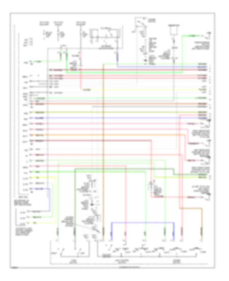 https://portal-diagnostov.com/license.html
Automotive Electricians Portal FZCO
Automotive Electricians Portal FZCO
https://portal-diagnostov.com/license.html
https://portal-diagnostov.com/license.html
Automotive Electricians Portal FZCO
Automotive Electricians Portal FZCOList of elements for Headlights Wiring Diagram, with DRL (1 of 2) for Toyota 4Runner SR5 2004:
- (in dash harness, behind left center of dash)
- (in left "b" pillar) left front door courtesy switch
- Acc
- Acc fuse 7.5a
- Auto
- Automatic light control sensor (on upper left side of dash)
- Becu
- Body ecu
- Center j/b (behind right center of dash)
- Cltb
- Clte
- Clts
- Combination switch
- Dcty
- Dimmer switch
- Driver side j/b (behind lower left end of dash)
- Drl
- E j19
- Ecu-ig fuse 10a
- Exterior lights system
- F12
- Flash
- Foglight switch
- Generator
- Gnd1
- Gnd2
- Haz
- Hazard switch
- Head
- Head tail
- Hf2
- High low
- Hot in on or acc
- Hot in on or start
- Hrly
- Ig1 fuse 15a
- J/c 15 (behind instrument cluster)
- J/c 18 & 19 (behind instru- j18 ment cluster)
- J/c 18 & 19 (behind instrument cluster)
- J/c 22 & 23 (behind instrument cluster)
- J/c 37 (behind right kick panel)
- J/c 5 (behind right kick panel)
- J/c 7 (behind left end of dash)
- J14
- J15
- J17
- J18 a
- J19
- J22 e
- J23 d
- Left
- Left rear door courtesy switch (bottom of left "c" pillar)
- Light control switch
- Mpx2
- Off
- Parking brake switch (behind upper left end of dash)
- Pcty
- Pkb
- Prg
- Rda
- Red
- Right
- Right front door courtesy switch (on right "b" pillar)
- Right rear door courtesy switch (bottom of right "c" pillar)
- Rlcy
- Rrcy
- Sig
- Tail
- Tail relay
- Trly
- Turn switch
Headlights Wiring Diagram, with DRL (2 of 2) for Toyota 4Runner SR5 2004
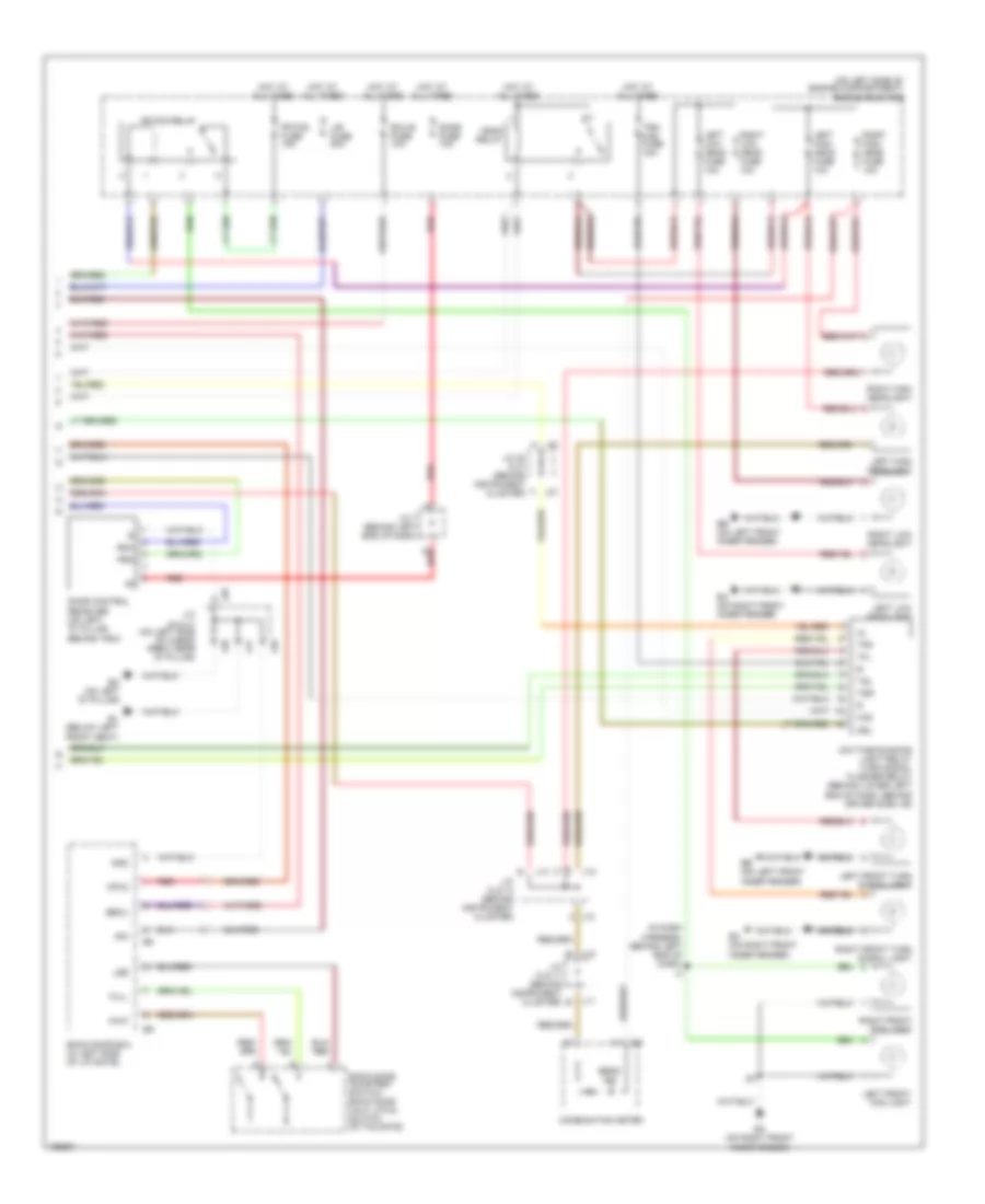 https://portal-diagnostov.com/license.html
Automotive Electricians Portal FZCO
Automotive Electricians Portal FZCO
https://portal-diagnostov.com/license.html
https://portal-diagnostov.com/license.html
Automotive Electricians Portal FZCO
Automotive Electricians Portal FZCOList of elements for Headlights Wiring Diagram, with DRL (2 of 2) for Toyota 4Runner SR5 2004:
- (in dash harness, behind left end of dash) i3
- (on left side of engine compartment) engine room r/b
- Back door courtesy switch, back door half latch switch (in tailgate)
- Back door ecu (in left side of liftgate)
- Beam ind
- Becu
- Bl (below left front seat)
- Bo (on left "d" pillar)
- Combination meter
- Daytime running light relay turn signal flasher relay (behind lower left end of dash, behind driver side j/b)
- Dome fuse 10a
- Door control receiver (on left "d" pillar, behind trim)
- Drl
- Ea (on right front
- Ea (on right front inner fender)
- Eb (on left front inner fender)
- Ecu-b fuse 10a
- Fr fog fuse 15a
- Fr fog relay
- Full
- Gnd
- Half
- Haz
- Head relay
- Hot at all times
- Inner fender)
- J/b fuse 50a
- J/c 10 & 11 (behind instrument cluster) b
- J/c 12 & 13 (behind instrument cluster)
- J/c 20 & 21 (behind instrument cluster)
- J/c 40 & 41 (on left side of cargo area, near "d" pillar)
- J/c 7 (behind left end of dash)
- J10
- J11
- J12
- J13
- J20
- J21
- J40
- J41
- Left front fog light
- Left front turn signal light
- Left high head fuse 10a
- Left high headlight
- Left low head fuse 10a
- Left low headlight
- Lse
- Mpx2
- Prg
- Rda
- Red
- Right front fog light
- Right front turn signal light
- Right high head fuse 10a
- Right high headlight
- Right low head fuse 10a
- Right low headlight
- Sig
- Tfl
- Tfr
- Trn- haz fuse 15a
- Tsl
- Tsr
Headlights Wiring Diagram, without DRL (1 of 2) for Toyota 4Runner SR5 2004
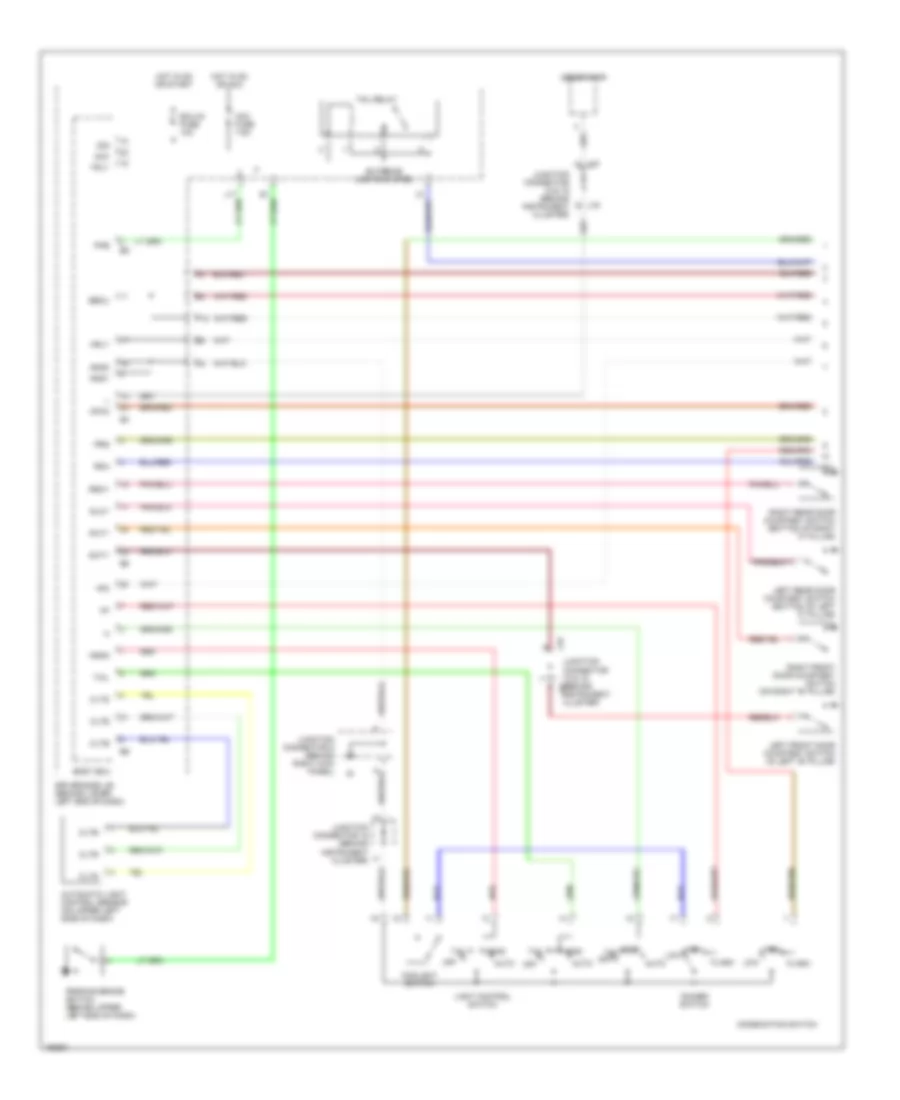 https://portal-diagnostov.com/license.html
Automotive Electricians Portal FZCO
Automotive Electricians Portal FZCO
https://portal-diagnostov.com/license.html
https://portal-diagnostov.com/license.html
Automotive Electricians Portal FZCO
Automotive Electricians Portal FZCOList of elements for Headlights Wiring Diagram, without DRL (1 of 2) for Toyota 4Runner SR5 2004:
- Acc
- Acc fuse 7.5a
- Auto
- Automatic light control sensor (on upper left side of dash)
- Becu
- Body ecu
- Cltb
- Clte
- Clts
- Combination switch
- Dcty
- Dimmer switch
- Driver side j/b (behind lower left end of dash)
- Ecu-ig fuse 10a
- Exterior lights system
- F12
- Flash
- Foglight switch
- Generator
- Gnd1
- Gnd2
- Head
- Head tail
- Hf2
- High
- High low
- Hot in on or acc
- Hot in on or start
- Hrly
- J18
- J19
- Junction connector 15 (behind instrument cluster)
- Junction connector 18 & 19 (behind instrument cluster)
- Junction connector 18 & 19 (behind j18 instrument cluster)
- Junction connector 5 (behind right kick panel)
- Left front door courtesy switch (in left "b" pillar)
- Left rear door courtesy switch (bottom of left "c" pillar)
- Light control switch
- Low
- Mpx2
- Off
- Parking brake switch (behind upper left end of dash)
- Pcty
- Pkb
- Prg
- Rda
- Red
- Right front door courtesy switch (on right "b" pillar)
- Right rear door courtesy switch (bottom of right "c" pillar)
- Rlcy
- Rrcy
- Sig
- Tail
- Tail relay
- Trly
Headlights Wiring Diagram, without DRL (2 of 2) for Toyota 4Runner SR5 2004
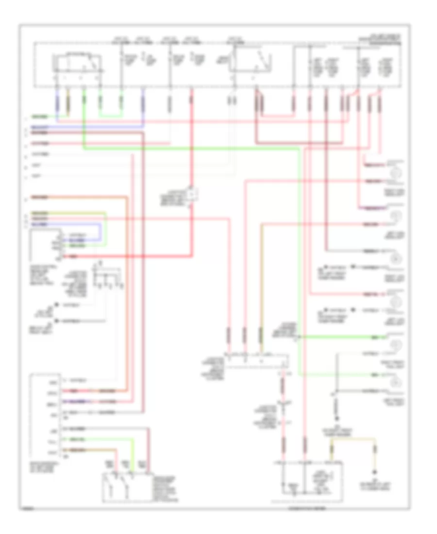 https://portal-diagnostov.com/license.html
Automotive Electricians Portal FZCO
Automotive Electricians Portal FZCO
https://portal-diagnostov.com/license.html
https://portal-diagnostov.com/license.html
Automotive Electricians Portal FZCO
Automotive Electricians Portal FZCOList of elements for Headlights Wiring Diagram, without DRL (2 of 2) for Toyota 4Runner SR5 2004:
- (except usa) tail ind
- (in dash harness, behind left end of dash) i3
- (on left side of engine compartment) engine room r/b
- (usa) head ind
- Back door courtesy switch, back door half latch switch (in tailgate)
- Back door ecu (in left side of liftgate)
- Beam ind
- Becu
- Bl (below left front seat)
- Bo (on left "d" pillar)
- C10
- Cluster)
- Combination meter
- Cylinder head)
- Dome fuse 10a
- Door control receiver (on left "d" pillar, behind trim)
- Ea (on right front
- Ea (on right front inner fender)
- Eb (on left front inner fender)
- Ecu-b fuse 10a
- Ef (on rear of left
- Fr fog fuse 15a
- Fr fog relay
- Full
- Gnd
- Half
- Head relay
- Hot at all times
- Inner fender)
- J/b fuse 50a
- J10
- J11
- J12
- J13
- J40
- J41
- Junction connector 10 & 11 (behind instrument b
- Junction connector 12 & 13 (behind instrument cluster)
- Junction connector 40 & 41 (on left side of cargo area, near "d" pillar)
- Junction connector 7 (behind left end of dash) d
- Left front fog light
- Left high head fuse 10a
- Left high headlight
- Left low head fuse 10a
- Left low headlight
- Lse
- Mpx2
- Prg
- Rda
- Red
- Right front fog light
- Right high head fuse 10a
- Right high headlight
- Right low head fuse 10a
- Right low headlight
- Sig
HORN
Horn Wiring Diagram for Toyota 4Runner SR5 2004
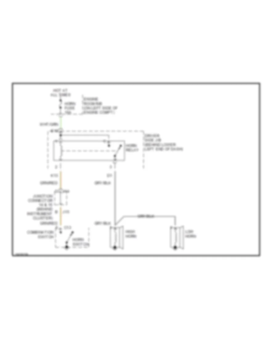 https://portal-diagnostov.com/license.html
Automotive Electricians Portal FZCO
Automotive Electricians Portal FZCO
https://portal-diagnostov.com/license.html
https://portal-diagnostov.com/license.html
Automotive Electricians Portal FZCO
Automotive Electricians Portal FZCOList of elements for Horn Wiring Diagram for Toyota 4Runner SR5 2004:
- B j15
- C j14
- C13
- Combination switch
- Driver side j/b (behind lower left end of dash)
- E10
- Engine room r/b (on left side of engine compt)
- High horn
- Horn fuse 10a
- Horn relay
- Horn switch
- Hot at all times
- Junction connector 14 & 15 (behind instrument cluster)
- K13
- Low horn
INSTRUMENT CLUSTER
Instrument Cluster Wiring Diagram (1 of 2) for Toyota 4Runner SR5 2004
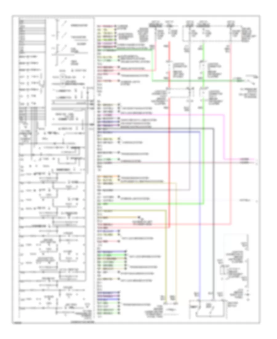 https://portal-diagnostov.com/license.html
Automotive Electricians Portal FZCO
Automotive Electricians Portal FZCO
https://portal-diagnostov.com/license.html
https://portal-diagnostov.com/license.html
Automotive Electricians Portal FZCO
Automotive Electricians Portal FZCOList of elements for Instrument Cluster Wiring Diagram (1 of 2) for Toyota 4Runner SR5 2004:
- (on left front of engine)
- (under center of rear seat, in fuel tank)
- (usa) tail ind (except usa)
- 4lo ind
- 4wd ind
- A/t oil temp ind
- A10
- A11
- A12
- A13
- A14
- A15
- A16
- A17
- A18
- A19
- A20
- Abs ind
- Air conditioning system
- Anti-lock brakes system
- B10
- B11
- B12
- B12 b13 b19 c3
- B13
- B14
- B15
- B16
- B17
- B18
- B19
- B2 b3 a13
- B20
- B8 c7 b16 b7 b18
- Beam ind
- Brake ind
- Buzzer
- C j10
- C10
- C11
- C11 c8 b9 b10
- C12
- C13
- C14
- C15
- C16
- C17
- C18
- C19
- C20
- Center diff lock ind
- Charge ind
- Combination meter
- Computer data lines system
- Cruise control system
- Cruise ind
- D10
- D11
- D12
- D13
- D14
- D15
- D16
- D17
- D18
- D19
- D20
- Dac ind
- Dome fuse 10a
- Door ind
- Driver side j/b (behind lower left end of dash)
- Driver's seat belt ind
- Ef (on rear of left cylinder head)
- Electronic suspension system
- Engine controls system
- Engine room r/b (on left side of engine compt)
- Fuel gauge
- Fuel ind
- Fuel sender
- Gauge fuse 7.5a
- Head (hi rh) fuse 10a
- Head ind
- Headlights system
- Hi ind
- Hot at all times
- Hot in on or start
- Hot w/ head relay energizied
- Hot w/ tail relay energizied
- Ign fuse 10a
- Illumination
- Interior lights system
- J/c 10 & 11 (behind instrument cluster)
- J/c 5 (behind right kick panel)
- J10
- J11
- J11 a
- Junction connector (behind instrument cluster)
- Junction connector (behind left end of dash)
- Junction connector 10 & 11 (behind instrument cluster)
- Junction connector 15 (behind instrument cluster)
- Junction connector 8 & 9 (behind instrument cluster)
- Lo ind
- Maint ind
- Malfunction indicator light
- N ind
- Odo/ trip
- Odo/trip switch
- Off ind
- Oil pressure ind
- Oil pressure switch
- Pnk
- Red
- Reset
- Slip ind
- Speedometer
- Srs ind
- Starting/charging system
- Tachometer
- Tail fuse 10a
- Temp gauge
- To tire pressure ind (diagram 2 0f 2)
- To tire pressure ind (diagram 2 of 2)
- Transmissions system
- Vsc trac ind
- Warning system
- Washer ind
- Wiper/washer system
Instrument Cluster Wiring Diagram (2 of 2) for Toyota 4Runner SR5 2004
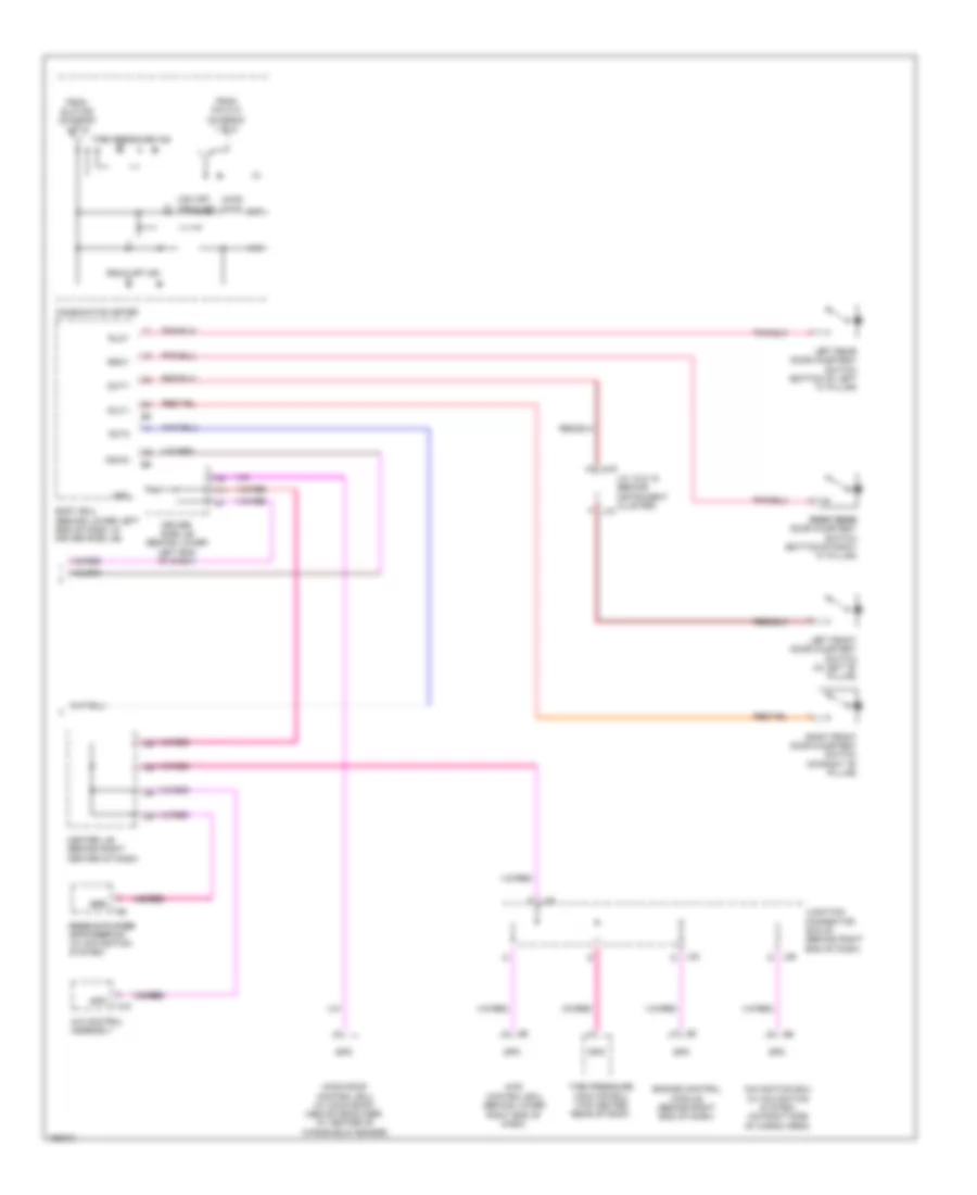 https://portal-diagnostov.com/license.html
Automotive Electricians Portal FZCO
Automotive Electricians Portal FZCO
https://portal-diagnostov.com/license.html
https://portal-diagnostov.com/license.html
Automotive Electricians Portal FZCO
Automotive Electricians Portal FZCOList of elements for Instrument Cluster Wiring Diagram (2 of 2) for Toyota 4Runner SR5 2004:
- (2wd)
- (4wd)
- 4wd control ecu (behind lower right end of dash)
- A/c control assembly
- A10
- A16
- Body ecu (behind lower left end of dash, in driver side j/b)
- C17
- Center j/b (behind right center of dash)
- Combination meter
- Dcty
- Dcy2
- Driver side j/b (behind lower left end of dash)
- Engine control module (behind right end of dash)
- From pin c13 (diagram 1 0f 2)
- From slip ind (diagram 1 0f 2)
- J/c 18 & 19 (behind instrument cluster) j18
- J19
- J29
- J30
- Junction connector 29 & 30 (behind right end of dash)
- K11
- Kswo
- Left front door courtesy switch (in left "b" pillar)
- Left rear door courtesy switch (bottom of left "c" pillar)
- Moon roof control ecu (w/ moon roof) (above headliner, at center of windshield header)
- Navigation ecu (w/ navigation system) (on right side of cargo area)
- Pcty
- Radio & player radio & player with display with display (w/ navigation system)
- Right front door courtesy switch (on right "b" pillar)
- Right rear right rear door courtesy switch (bottom of right "c" pillar)
- Rlcy
- Rrcy
- Rsca off ind
- Spd
- Spd spd
- Tire pressure ind
- Tire pressure monitor ecu (top center rear of roof)
- Trac off
- Vsc off
INTERIOR LIGHTS
Courtesy Lamps Wiring Diagram for Toyota 4Runner SR5 2004
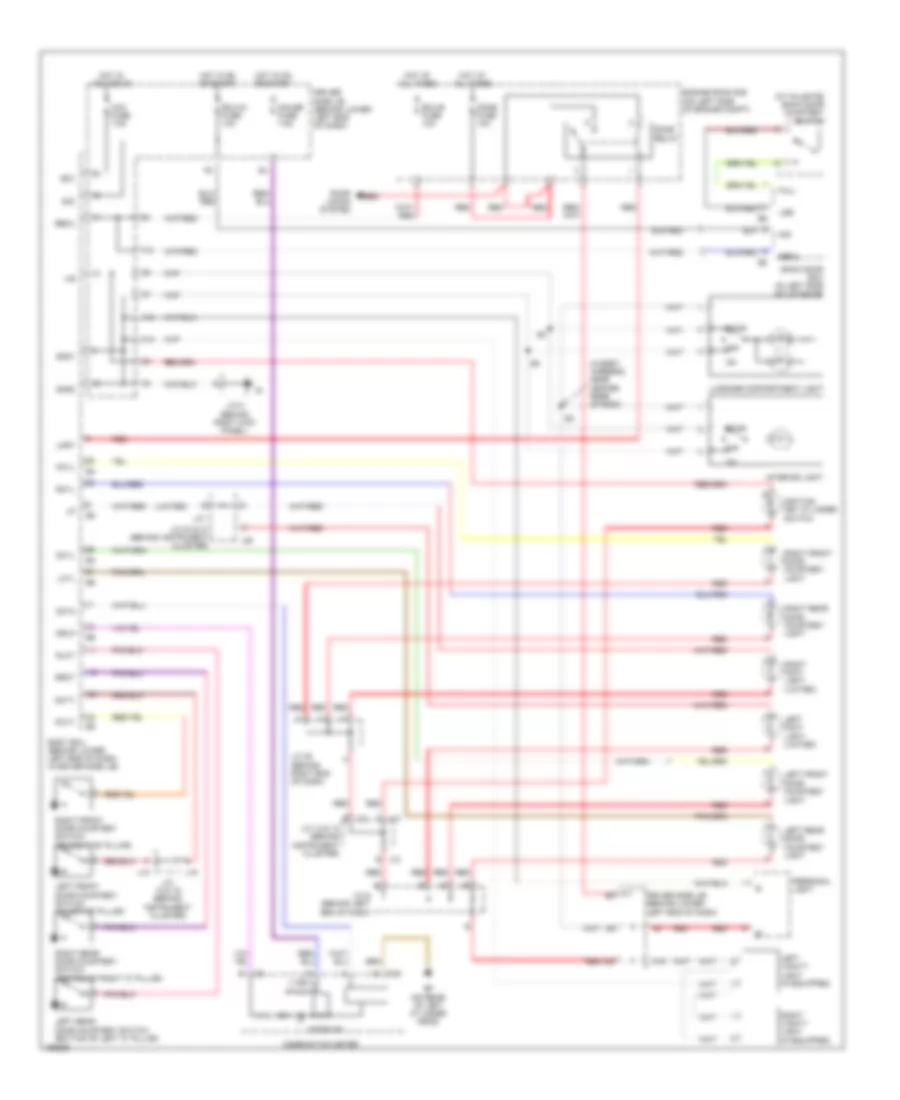 https://portal-diagnostov.com/license.html
Automotive Electricians Portal FZCO
Automotive Electricians Portal FZCO
https://portal-diagnostov.com/license.html
https://portal-diagnostov.com/license.html
Automotive Electricians Portal FZCO
Automotive Electricians Portal FZCOList of elements for Courtesy Lamps Wiring Diagram for Toyota 4Runner SR5 2004:
- (in body harness, near center rear of roof)
- (in tailgate) back door courtesy switch
- (limited)
- (on left side of engine compt)
- A12
- A18
- A19
- Acc
- Acc fuse 7.5a
- B j12
- Back door ecu (in left side of liftgate)
- Becu
- Body ecu (behind lower left end of dash, in driver side j/b)
- C j13
- C10
- Combination meter
- Dcty
- Dcy2
- Dcyl
- Dome fuse 10a
- Dome relay
- Door
- Door ind
- Door locks system
- Driver side j/b (behind lower left end of dash)
- Drlp
- Ecu-b fuse 10a
- Ecu-ig fuse 10a
- Ef (on rear of left cylinder head)
- Engine room r/b
- F12
- Full
- Gauge fuse 7.5a
- Gnd1
- Gnd2
- Hot at all times
- Hot in acc or on
- Hot in on or start
- Ignition key cylinder switch
- Ile
- Interior light
- J/c 12 & 13 (behind instrument cluster)
- J/c 18 & 19 (behind instrument cluster)
- J/c 20 & 21 (behind instrument cluster)
- J/c 35 (behind right end of dash)
- J/c 5 (behind right kick panel)
- J/c 6 (behind left end of dash)
- J18
- J19
- J20
- J21
- J22
- Lcyl
- Left foot light (limited)
- Left front door courtesy light
- Left front door courtesy switch (in left "b" pillar)
- Left rear door courtesy light
- Left rear door courtesy switch (bottom of left "c" pillar)
- Left vanity light (if equipped)
- Lmry
- Lse
- Luggage compartment light
- Off
- Pcty
- Pcyl
- Personal light
- Rcyl
- Red
- Right foot light (limited)
- Right front door courtesy light
- Right front door courtesy switch (on right "b" pillar)
- Right rear door courtesy light
- Right rear door courtesy switch (bottom of right "c" pillar)
- Right vanity light (if equipped)
- Rlcy
- Rrcy
- Sig
Instrument Illumination Wiring Diagram for Toyota 4Runner SR5 2004
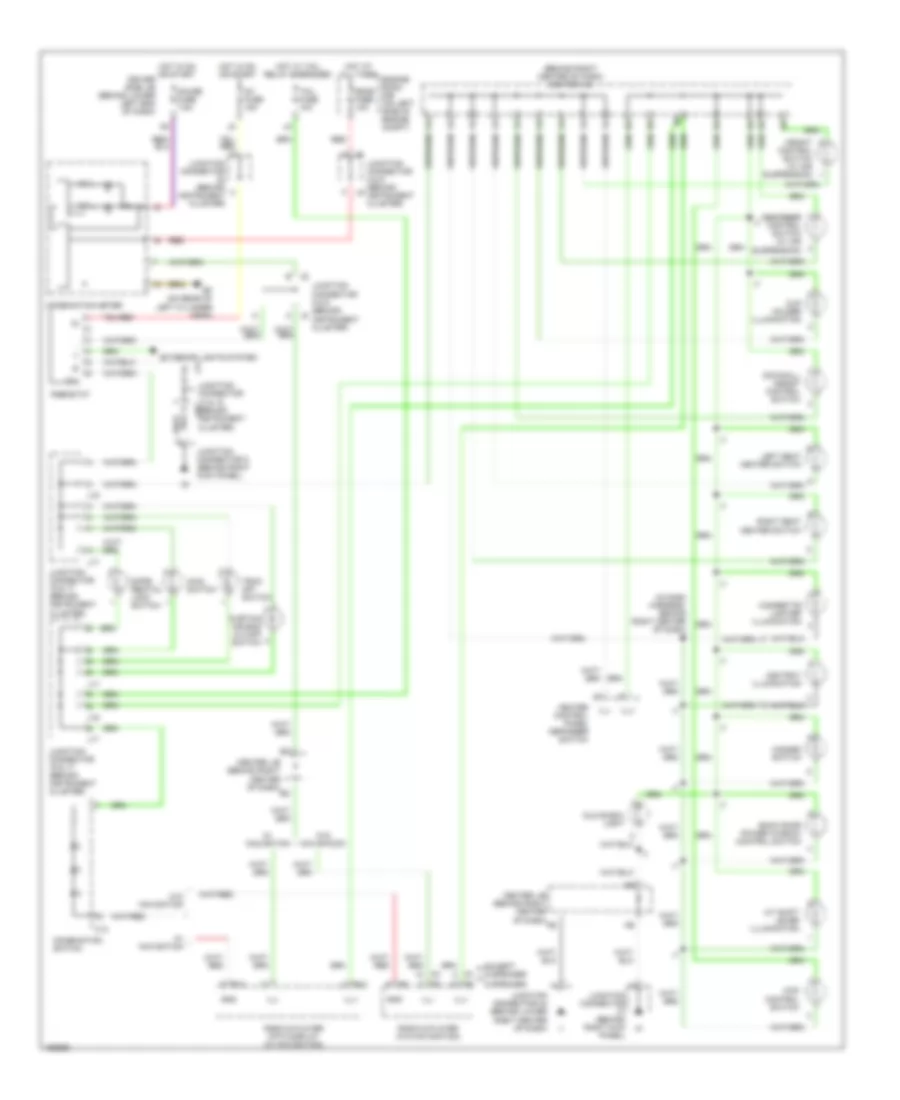 https://portal-diagnostov.com/license.html
Automotive Electricians Portal FZCO
Automotive Electricians Portal FZCO
https://portal-diagnostov.com/license.html
https://portal-diagnostov.com/license.html
Automotive Electricians Portal FZCO
Automotive Electricians Portal FZCOList of elements for Instrument Illumination Wiring Diagram for Toyota 4Runner SR5 2004:
- (behind right center of dash) center j/b
- (in dash harness, behind right center of dash) i7
- 4wd control switch
- 6 speaker
- A/t shift lever illumination
- Absorber control switch (w/ air suspension)
- Ashtray illumination
- Back door power window control switch
- C13
- Center j/b (behind right center of dash)
- Cigarette lighter illumination
- Combination meter
- Combination switch
- Cup holder illumination
- Curtain air bag cutoff switch
- Diffe- rential lock switch
- Dome fuse 10a
- Downhill assist control switch
- Driver side j/b (behind lower left end of dash)
- Ef (on rear of left cylinder head)
- Engine room r/b (on left side of engine compt)
- Except 6 speaker
- Exterior lights system
- Gauge fuse 7.5a
- Glove box light
- Gnd
- Hazard switch
- Heater control panel defogger switch
- Height control switch (w/ air suspension)
- Hot at all times
- Hot in on or start
- Hot w/ tail relay energized
- Ig1 fuse 15a
- Ill
- Ill+
- Ill-
- J14
- J16
- J17
- Junction connector (behind instrument cluster)
- Junction connector (behind right kick panel)
- Junction connector 14 & 15 (behind instrument j15 cluster)
- Junction connector 16 & 17 (behind instrument cluster)
- Junction connector 24 (behind lower right center of dash)
- Junction connector 5 (behind right kick panel)
- Junction connector 8 & 9 (behind instrument cluster)
- Left seat heater switch
- Main switch
- R10
- R12
- Radio & player (w/o navigation)
- Radio & player with display (w/ navigation)
- Red
- Rheostat
- Right seat heater switch
- Tail fuse 10a
- Trac off switch
- W/ navigation
- W/o navigation
PASSIVE RESTRAINTS
Passive Restraints Wiring Diagram for Toyota 4Runner SR5 2004
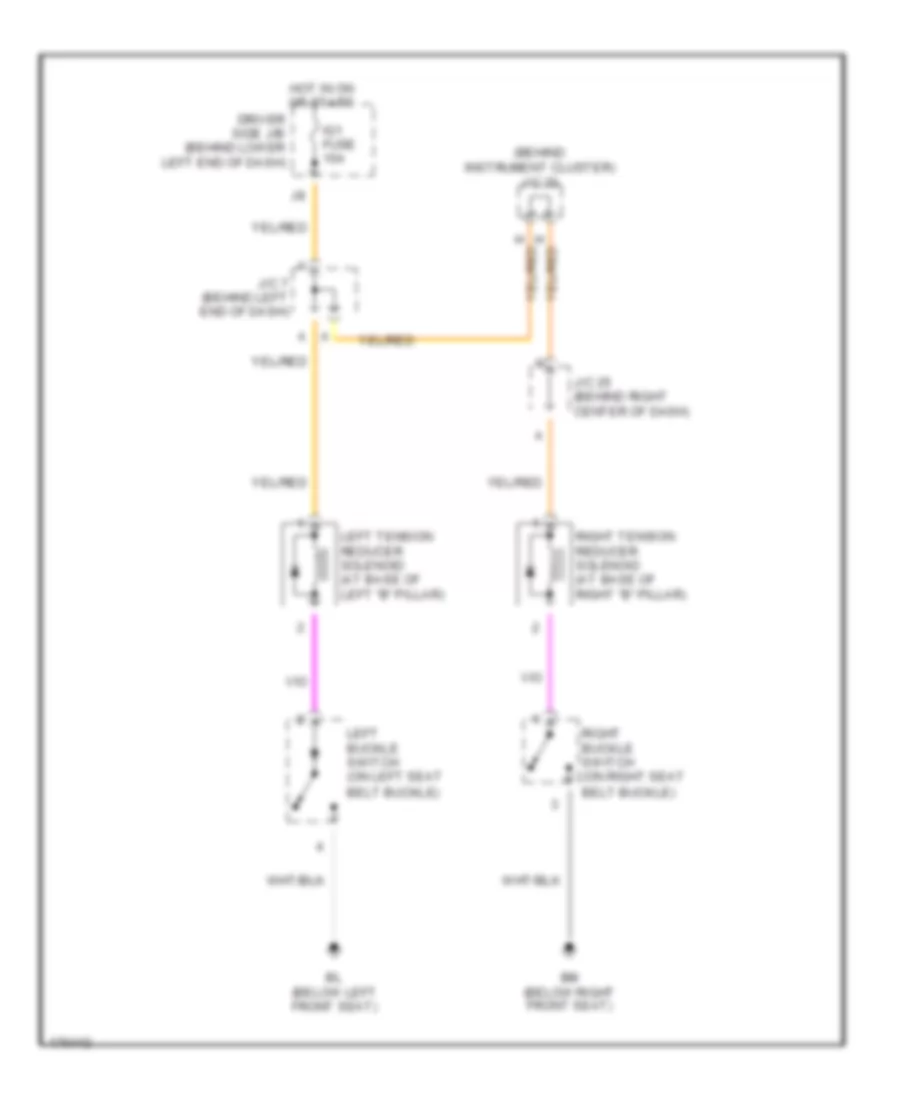 https://portal-diagnostov.com/license.html
Automotive Electricians Portal FZCO
Automotive Electricians Portal FZCO
https://portal-diagnostov.com/license.html
https://portal-diagnostov.com/license.html
Automotive Electricians Portal FZCO
Automotive Electricians Portal FZCOList of elements for Passive Restraints Wiring Diagram for Toyota 4Runner SR5 2004:
- (behind instrument cluster)
- Belt buckle)
- Bl (below left front seat)
- Bm (below right front seat)
- Driver side j/b (behind lower left end of dash)
- Hot in on or start
- Ig1 fuse 15a
- J/c 20
- J/c 25 (behind right center of dash)
- J/c 7 (behind left end of dash)
- Left buckle switch (on left seat
- Left tension reducer solenoid (at base of left "b" pillar)
- Right buckle switch (on right seat
- Right tension reducer solenoid (at base of right "b" pillar)
POWER DISTRIBUTION
Power Distribution Wiring Diagram (1 of 2) for Toyota 4Runner SR5 2004
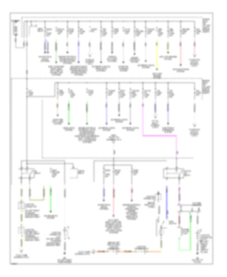 https://portal-diagnostov.com/license.html
Automotive Electricians Portal FZCO
Automotive Electricians Portal FZCO
https://portal-diagnostov.com/license.html
https://portal-diagnostov.com/license.html
Automotive Electricians Portal FZCO
Automotive Electricians Portal FZCOList of elements for Power Distribution Wiring Diagram (1 of 2) for Toyota 4Runner SR5 2004:
- (behind left end of dash) junction connector 7
- A/f heater fuse 15a
- Abs mtr fuse 40a
- Abs sol fuse 50a
- Ac1
- Ac115v inv fuse 15a
- Ac115v inv relay
- Ac2
- Air conditioning system
- Air conditioning systems
- Air conditioning, engine controls, transmissions & cruise control systems
- Air sus fuse 50a
- Alt fuse 140a
- Alt-s fuse 7.5a
- Am1 fuse 50a
- Am2 fuse 30a
- Anti-lock brakes system
- Anti-theft, body computer, interior lights, power windows, door locks &
- Batt chg fuse 30a
- Battery
- Bo (on left "d" pillar)
- Body computer, door locks, anti-theft & power tops systems
- Computer data lines system
- Defog relay
- Dome fuse 10a
- Dr/lck fuse 20a
- Eb (on left front inner fender)
- Ecu-b fuse 10a
- Efi fuse 20a
- Electronic suspension system
- Engine controls system
- Engine controls, exterior lights, transmissions, cruise control, electronic suspension, shift interlock & anti-lock brakes systems
- Engine controls, transmissions & cruise control systems
- Engine controls, warning, garage door opener, instrument cluster & headlights systems
- Engine room r/b (on left side of engine compt)
- Etcs fuse 10a
- Exterior lights & headlights systems
- Exterior lights system
- Fr fog fuse 15a
- From short pin (diagram 1 of 2)
- Gnd
- Head relay
- Headlights system
- Heater fuse 60a
- Horn fuse 10a
- Horns & anti-theft systems
- Ig relay
- J/b fuse 50a
- J41
- Junction connector (behind right kick panel)
- Junction connector (on left front of engine compartment, near battery)
- Junction connector 1 (on left front of engine compartment, near battery)
- Junction connector 2 & 3 (on left front of engine compartment, near battery)
- Junction connector 20
- Junction connector 40 & 41 j40 (on left side of cargo area, near "d" pillar)
- Main switch
- Navigation & sound systems
- Obd fuse 7.5a
- Power outlet (115v)
- Power seats system
- Radio fuse 20a
- Red
- Seat heater fuse 25a
- Short pin
- Starting/ charging system
- Stop fuse 10a
- To ecu-b (diagram 1 of 2)
- To ig 1 fuse (diagram 2 of 2)
- To ignition switch (diagram 2 0f 2)
- To ignition switch (diagram 2 of 2)
- To tail relay (diagram 2 of 2)
- Towing brk fuse 30a
- Towing fuse 30a
- Towing fuse 40a
- Trn- haz fuse 15a
- Voltage inverter
Power Distribution Wiring Diagram (2 of 2) for Toyota 4Runner SR5 2004
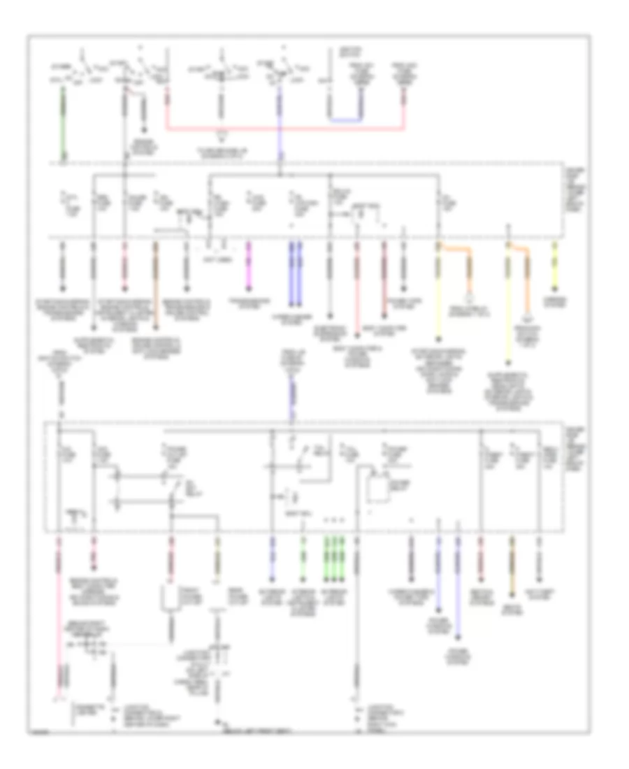 https://portal-diagnostov.com/license.html
Automotive Electricians Portal FZCO
Automotive Electricians Portal FZCO
https://portal-diagnostov.com/license.html
https://portal-diagnostov.com/license.html
Automotive Electricians Portal FZCO
Automotive Electricians Portal FZCOList of elements for Power Distribution Wiring Diagram (2 of 2) for Toyota 4Runner SR5 2004:
- (behind right center of dash) center j/b
- (not used)
- 4wd fuse 20a
- A11
- Acc
- Acc fuse 7.5a
- Am1
- Am2
- Anti-theft system
- B11
- B12
- B13
- Bcm
- Bl (below left front seat)
- Body computer & power windows systems
- Body computer system
- Body ecu
- Cig fuse 10a
- Cigarette lighter
- D p/seat fuse 30a
- Dc skt relay
- Driver side j/b (behind lower left end of dash)
- E12
- E16
- E20
- E22
- E23
- Ecu-ig fuse 10a
- Electronic suspension system
- Engine controls system
- Engine controls, body computer, mirrors, air conditioning & sound systems
- Engine controls, cruise control & anti-lock brakes systems
- Engine controls, transmissions & cruise control systems
- Exterior lights system
- F13
- Fr wip-wsh fuse 30a
- From am1 fuse (diagram 1 of 2)
- From am2 fuse (diagram 1 of 2)
- From ig relay (diagram 1 of 2)
- From ignition switch (diagram 2 of 2)
- From j/b
- From main switch (diagram 1 of 2)
- Front power outlet
- Fuse 50 (diagram 1 of 2)
- Gauge fuse 7.5a
- Ig1
- Ig1 fuse 15a
- Ig2
- Ign fuse 10a
- Ignition switch
- Interior lights & instrument cluster systems
- J11
- J13
- J25
- J28
- J29
- J30
- J31
- J32
- J40
- J41
- Junction connector 24 (behind lower right center of dash)
- Junction connector 5 (behind right kick panel)
- K10
- L17
- L20
- Lock
- Mirrors system
- Near "d" pillar)
- Off on
- On off
- P p/seat fuse 30a
- Pnk
- Power fuse 30a
- Power outlet fuse 15a
- Power relay
- Power tops system
- Power windows system
- Rear power outlet
- Red
- Rr wash fuse 15a
- Seats & memory systems
- Seats system
- Secu/ horn fuse 10a
- Sig
- Srs fuse 10a
- St2
- Sta fuse 7.5a
- Start
- Starting/charging, engine controls & transmissions systems
- Starting/charging, engine controls, instrument cluster, interior lights & warning systems
- Starting/charging, exterior lights, defogger, air conditioning, door locks & anti-lock brakes systems
- Tail fuse 10a
- Tail relay
- To driver side j/b (diagram 2 of 2)
- Transmissions system
- Trly
- Wig
- Wiper/washer & power tops systems
- Wiper/washer system
POWER DOOR LOCKS
Power Door Locks Wiring Diagram (1 of 2) for Toyota 4Runner SR5 2004
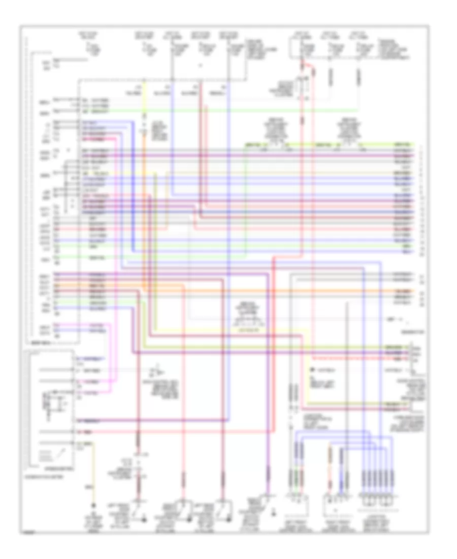 https://portal-diagnostov.com/license.html
Automotive Electricians Portal FZCO
Automotive Electricians Portal FZCO
https://portal-diagnostov.com/license.html
https://portal-diagnostov.com/license.html
Automotive Electricians Portal FZCO
Automotive Electricians Portal FZCOList of elements for Power Door Locks Wiring Diagram (1 of 2) for Toyota 4Runner SR5 2004:
- (behind
- (behind instrument cluster)
- (below left front seat)
- Acc
- Acc fuse 7.5a
- Act+
- Act-
- Actd
- B10
- Bdr1
- Becu
- Body ecu
- Bzr
- Bzr2
- C10
- Combination meter
- Dcty
- Dcy2
- Dome fuse 10a
- Door control receiver (on left "d" pillar, behind trim)
- Door ind
- Dr/lck fuse 20a
- Driver side j/b (behind lower left end of dash)
- Drlp
- Ecu-b fuse 10a
- Ecu-ig fuse 10a
- Ef (on rear of left cylinder head)
- Engine room r/b (on left side of engine compartment)
- F12
- Gauge fuse 7.5a
- Generator
- Gnd1
- Gnd2
- Hot at all times
- Hot in on or acc
- Hot in on or start
- Ig1 fuse 15a
- Instrument cluster)
- Instrument cluster) junction connector 14 & 15
- Instrument cluster) junction connector 18 & 19
- J/c 18 & 19
- J/c 25 (behind right center of dash
- J/c 8 & 9 (behind instrument cluster)
- J14
- J15
- J18
- J19
- Junction connector 38 (in left front door)
- Junction connector 6 (behind left end of dash)
- K15
- Ksw
- L10
- L11
- L16
- L18
- L22
- L23
- Left front door courtesy switch (in left "b" pillar)
- Left front door lock control switch
- Left rear door courtesy switch (bottom of left "c" pillar)
- Lsr
- Lswd
- Lswp
- Mpx2
- Pcty
- Power fuse 30a
- Prg
- Rda
- Red
- Right front door courtesy switch (on right "b" pillar)
- Right front door lock control switch
- Right rear door courtesy switch (bottom of right "c" pillar)
- Rlcy
- Rrcy
- Sig
- Skid control ecu (behind left end of dash, above driver side j/b)
- Sp1
- Spd
- Speedometer
- Ul1
- Ul3
- Wireless door lock buzzer (on left rear of of engine compt)
Power Door Locks Wiring Diagram (2 of 2) for Toyota 4Runner SR5 2004
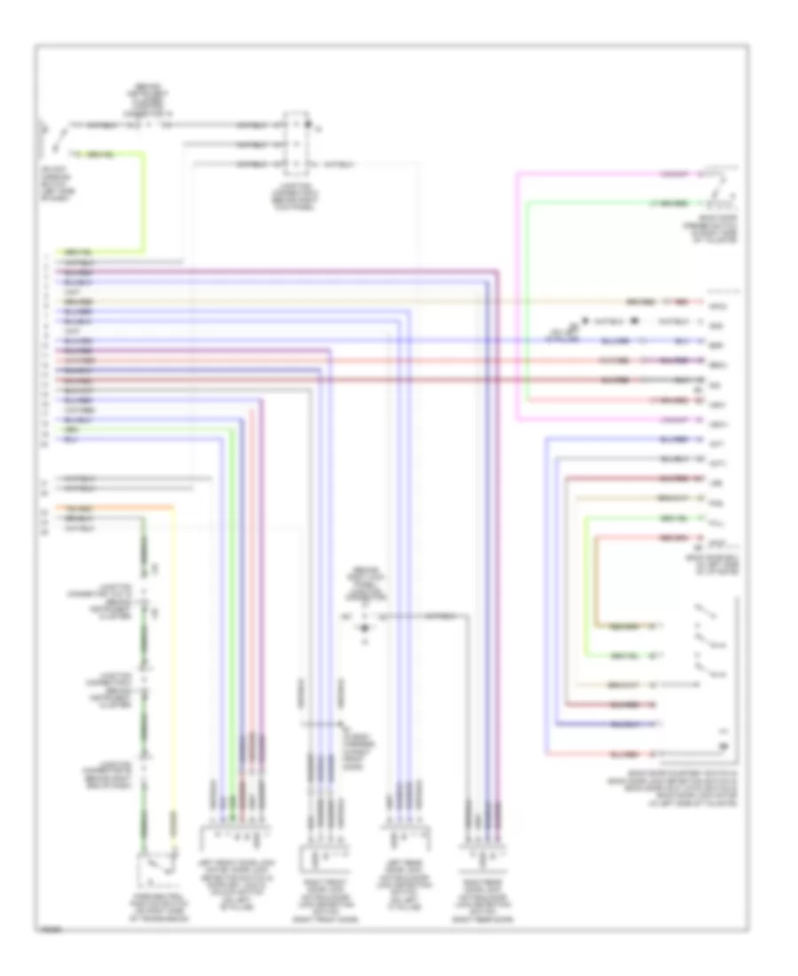 https://portal-diagnostov.com/license.html
Automotive Electricians Portal FZCO
Automotive Electricians Portal FZCO
https://portal-diagnostov.com/license.html
https://portal-diagnostov.com/license.html
Automotive Electricians Portal FZCO
Automotive Electricians Portal FZCOList of elements for Power Door Locks Wiring Diagram (2 of 2) for Toyota 4Runner SR5 2004:
- (behind instrument cluster) junction connector 15
- (behind right kick panel) junction connector
- Act+
- Act-
- B1 (in body harness, in right front door)
- Back door courtesy switch & back door lock detection switch & back door half latch switch & back door lock motor (in left side of tailgate)
- Back door ecu (in left side of liftgate)
- Back door opener switch (in right side of tailgate)
- Bdr
- Becu
- Bo (on left ``d" pillar)
- Full
- Gnd
- Half
- Hsw+
- Hsw-
- J18
- J19
- Junction connector 18 & 19 (behind instrument cluster)
- Junction connector 35 (behind right end of dash)
- Junction connector 5 (behind right kick panel)
- Junction connector 8 (behind instrument cluster)
- Left front door lock motor, door lock detection switch & door key lock & unlock switch (on left "b" pillar)
- Left rear door lock motor & door lock detectoin switch (on left "c" pillar)
- Lse
- Lssr
- Mpx2
- Park/neutral position switch (on right side of transmission)
- Pos
- Red
- Right front door lock motor & door lock detection switch (right front door)
- Right rear door lock motor & door lock detectoin switch (right rear door)
- Sig
- Unlock warning switch (left side of dash)
POWER MIRRORS
Electrochromic Mirror Wiring Diagram for Toyota 4Runner SR5 2004
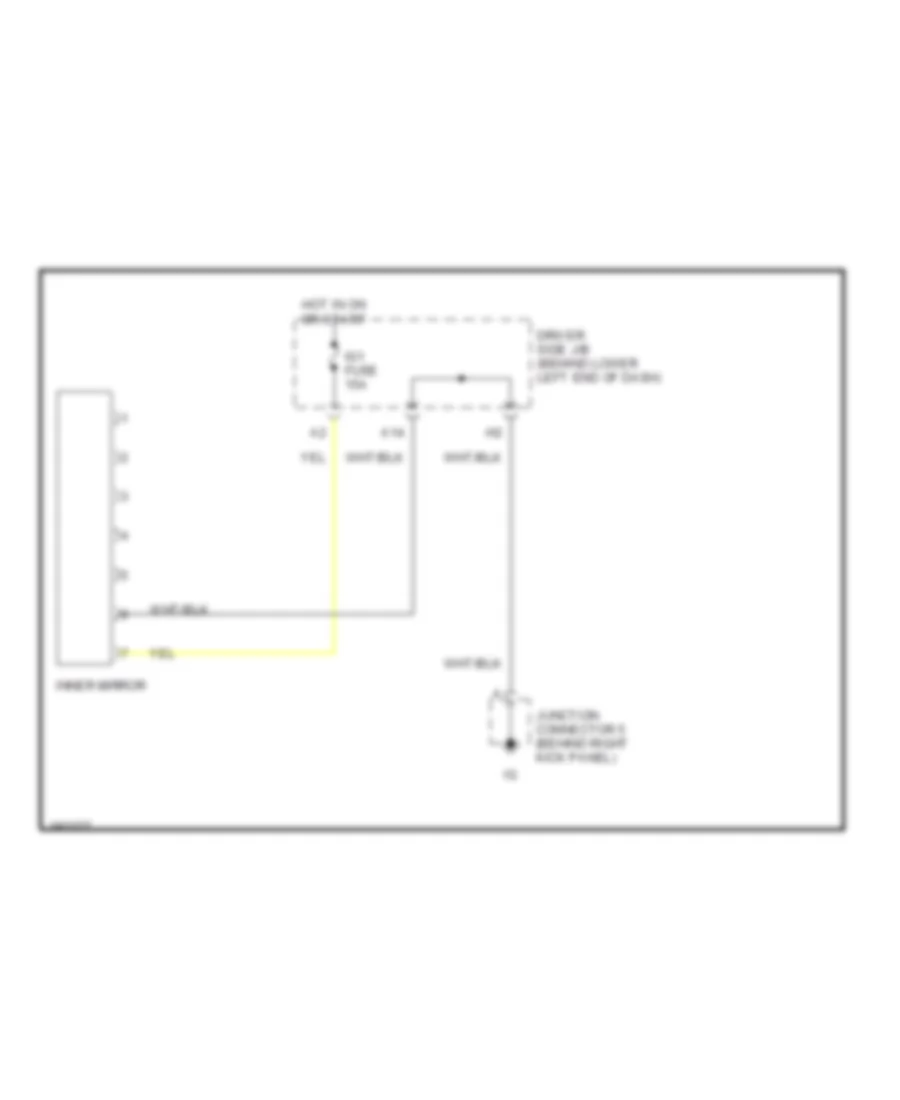 https://portal-diagnostov.com/license.html
Automotive Electricians Portal FZCO
Automotive Electricians Portal FZCO
https://portal-diagnostov.com/license.html
https://portal-diagnostov.com/license.html
Automotive Electricians Portal FZCO
Automotive Electricians Portal FZCOList of elements for Electrochromic Mirror Wiring Diagram for Toyota 4Runner SR5 2004:
- A14
- Driver side j/b (behind lower left end of dash)
- Hot in on or start
- Ig1 fuse 15a
- Inner mirror
- Junction connector 5 (behind right kick panel)
Power Mirrors Wiring Diagram for Toyota 4Runner SR5 2004
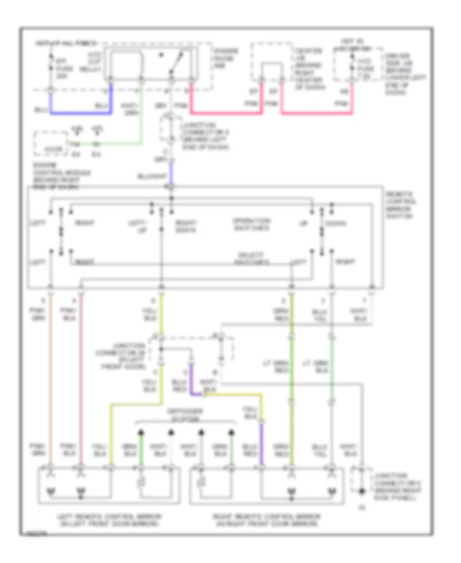 https://portal-diagnostov.com/license.html
Automotive Electricians Portal FZCO
Automotive Electricians Portal FZCO
https://portal-diagnostov.com/license.html
https://portal-diagnostov.com/license.html
Automotive Electricians Portal FZCO
Automotive Electricians Portal FZCOList of elements for Power Mirrors Wiring Diagram for Toyota 4Runner SR5 2004:
- 4.0l
- 4.7l
- Acc cut relay
- Acc fuse 7.5a
- Accr
- Center j/b (behind right center of dash)
- Defogger system
- Down
- Driver side j/b (behind lower left end of dash)
- Efi fuse 20a
- Engine control module (behind right end of dash)
- Engine room r/b
- Hot at all times
- Hot in acc or on
- Junction connector 38 (in left front door)
- Junction connector 5 (behind right kick panel)
- Junction connector 6 (behind left end of dash)
- Left
- Left remote control mirror (in left front door mirror)
- Left/ up
- Operation switches
- Pnk
- Remote control mirror switch
- Right
- Right remote control mirror (in right front door mirror)
- Right/ down
- Select switches
POWER SEATS
Driver Power Seat Wiring Diagram for Toyota 4Runner SR5 2004
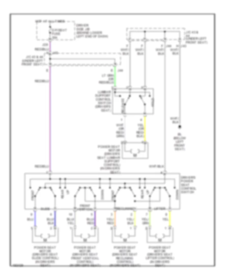 https://portal-diagnostov.com/license.html
Automotive Electricians Portal FZCO
Automotive Electricians Portal FZCO
https://portal-diagnostov.com/license.html
https://portal-diagnostov.com/license.html
Automotive Electricians Portal FZCO
Automotive Electricians Portal FZCOList of elements for Driver Power Seat Wiring Diagram for Toyota 4Runner SR5 2004:
- Bl (below left front seat)
- D p/seat fuse 30a
- Down
- Driver side j/b (behind lower left end of dash)
- Driver's power seat control switch
- Front
- Front vertical
- Hold
- Hot at all times
- J/c 43 & (under left front seat)
- J/c 43 & 44 (under left front seat)
- J29
- J43
- J44
- Lifter
- Lumbar support control switch (driver's seat)
- Power seat motor (driver's seat front vertical control) (in driver's seat)
- Power seat motor (driver's seat lifter control) (in driver's seat)
- Power seat motor (driver's seat lumbar support control) (in driver's seat)
- Power seat motor (driver's seat reclining control) (in driver's seat)
- Power seat motor (driver's seat slide control) (in driver's seat)
- Rear
- Reclining
- Release
- Slide
Heated Seats Wiring Diagram for Toyota 4Runner SR5 2004
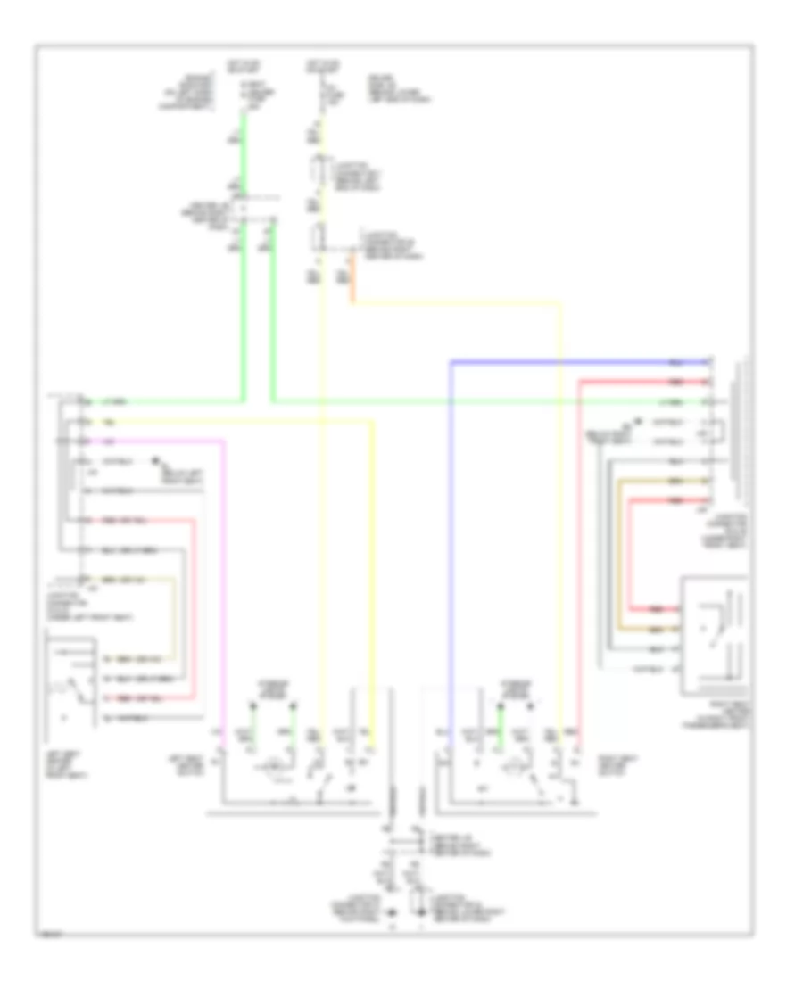 https://portal-diagnostov.com/license.html
Automotive Electricians Portal FZCO
Automotive Electricians Portal FZCO
https://portal-diagnostov.com/license.html
https://portal-diagnostov.com/license.html
Automotive Electricians Portal FZCO
Automotive Electricians Portal FZCOList of elements for Heated Seats Wiring Diagram for Toyota 4Runner SR5 2004:
- Bl (below left front seat)
- Bm (below right front seat)
- Center j/b (behind right center of dash)
- Driver side j/b (behind lower left end of dash)
- Engine room r/b (on left side of engine compartment)
- Hot in on or start
- Ig1 fuse 15a
- Interior lights system
- J43
- J44
- J45
- J46
- Junction connector 24 (behind lower right center of dash)
- Junction connector 25 (behind right center of dash)
- Junction connector 37 (behind right kick panel)
- Junction connector 43 & 44 (under left front seat)
- Junction connector 45 & 46 (under right front seat)
- Junction connector 7 (behind left end of dash)
- Left seat heater (in left front seat)
- Left seat heater switch
- Red
- Right seat heater (in right front passenger's seat)
- Right seat heater switch
- Seat heater fuse 25a
Passenger Power Seat Wiring Diagram for Toyota 4Runner SR5 2004
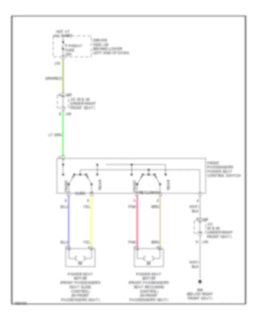 https://portal-diagnostov.com/license.html
Automotive Electricians Portal FZCO
Automotive Electricians Portal FZCO
https://portal-diagnostov.com/license.html
https://portal-diagnostov.com/license.html
Automotive Electricians Portal FZCO
Automotive Electricians Portal FZCOList of elements for Passenger Power Seat Wiring Diagram for Toyota 4Runner SR5 2004:
- Bm (below right front seat)
- Driver side j/b (behind lower left end of dash)
- Front
- Front passenger's power seat control switch
- Hot at all times
- J/c 45 & 46 (under right front seat)
- J32
- J45
- J46
- J46 f
- P p/seat fuse 30a
- Pnk
- Power seat motor (front passenger's seat reclining control) (in front passenger's seat)
- Power seat motor (front passenger's seat slide control) (in front passenger's seat)
- Rear
- Reclining
- Slide
POWER TOP/SUNROOF
Power Top/Sunroof Wiring Diagram for Toyota 4Runner SR5 2004
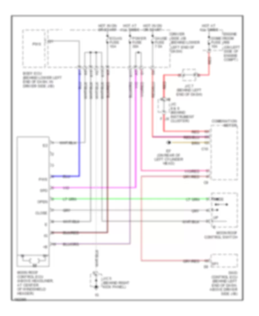 https://portal-diagnostov.com/license.html
Automotive Electricians Portal FZCO
Automotive Electricians Portal FZCO
https://portal-diagnostov.com/license.html
https://portal-diagnostov.com/license.html
Automotive Electricians Portal FZCO
Automotive Electricians Portal FZCOList of elements for Power Top/Sunroof Wiring Diagram for Toyota 4Runner SR5 2004:
- (on left side of engine compt)
- A11
- A13
- A15
- Body ecu (behind lower left end of dash, in driver side j/b)
- C10
- Close
- Combination meter
- Dome fuse 10a
- Driver side j/b (behind lower
- Ecu-ig fuse 10a
- Ef (on rear of left cylinder head)
- Engine room r/b
- Gauge fuse 7.5a
- Hot at all times
- Hot in on or start
- J/c 5 (behind right kick panel)
- J/c 7 (behind left end of dash)
- J/c 8 & 9 (behind instrument cluster)
- Left end of dash)
- Moon roof control ecu (above headliner, at center of windshield header)
- Moon roof control switch
- Open
- Power fuse 30a
- Pws
- Red
- Skid control ecu (behind left end of dash, above driver side j/b)
- Slide
- Sp1
- Spd
POWER WINDOWS
Power Windows Wiring Diagram for Toyota 4Runner SR5 2004
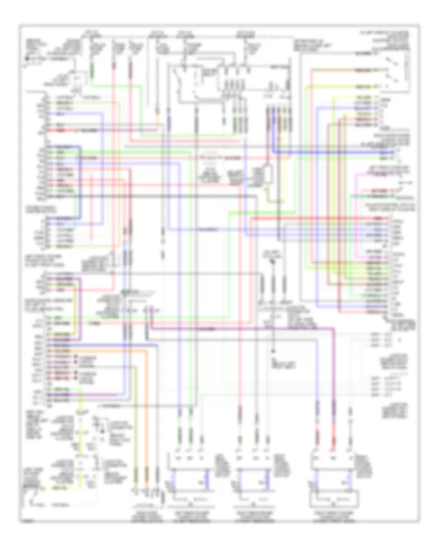 https://portal-diagnostov.com/license.html
Automotive Electricians Portal FZCO
Automotive Electricians Portal FZCO
https://portal-diagnostov.com/license.html
https://portal-diagnostov.com/license.html
Automotive Electricians Portal FZCO
Automotive Electricians Portal FZCOList of elements for Power Windows Wiring Diagram for Toyota 4Runner SR5 2004:
- (behind right kick panel) j/c 5
- (in left side of tailgate) back door courtesy switch, back door half latch switch
- (left side of dash) unlock warning switch
- (on left "d" pillar) bo
- (on left rear of engine compt)
- A j19
- Acc
- Acc fuse 7.5a
- B j14
- B10
- Back door ecu (in left side of liftgate)
- Back door power window control switch
- Back door power window motor (in left side of tailgate)
- Bddn
- Bdn
- Bdr
- Bdr1
- Bdup
- Becu
- Bl (below left front seat)
- Body ecu
- Body ecu (behind lower left end of dash, in driver side j/b)
- Bup
- Bzr
- Bzr2
- C j15
- Com
- Dcty
- Dome fuse 10a
- Door control receiver (on left "d" pillar, behind trim)
- Down
- Dr/lck fuse 20a
- Driver side j/b (behind lower left end of dash)
- Ecu-b fuse 10a
- Ecu-ig fuse 10a
- Engine room r/b (on left side of engine compt)
- F12
- Full
- Gnd
- Gnd1
- Gnd2
- Half
- Hot at all times
- Hot in acc or on
- Hot in on or start
- Ic+
- Ic-
- Ic1
- Ic2
- Interior lights system
- J/c 20 (behind instrument cluster)
- J/c 38 (in left front door)
- J18 e
- J22
- J23
- J25
- J28
- J40
- J41
- Junction connector (behind instrument cluster)
- Junction connector (behind right kick panel)
- Junction connector 14 & 15 (behind instrument cluster)
- Junction connector 18 & 19 (behind instrument cluster)
- Junction connector 22 & 23 (behind c instrument cluster)
- Junction connector 33 (behind right end of dash)
- Junction connector 40 & 41 (on left side of cargo area, near "d" pillar)
- Junction connector 7 (behind left end of dash)
- Junction connector 7 (behind left end of dash) d
- Ksw
- Left front door key lock & unlock switch
- Left front power window motor (in left front door)
- Left rear power window control switch
- Left rear power window motor (in left rear door)
- Lse
- Mpx2
- Pcty
- Pls
- Pls2
- Power fuse 30a
- Power relay
- Power window master switch
- Prg
- Pws
- Rda
- Red
- Right front power window control switch
- Right front power window motor (in right front door)
- Right rear power window control switch
- Right rear power window motor (in right rear door)
- Rlcy
- Rld
- Rlu
- Rrcy
- Rrd
- Rru
- Sig
- Ssrb
- Tailgate control switch (right side of tailgate)
- Ul3
- Vcc
- W/l 1
- W/l 2
- Wire- less door lock buzzer
RADIO
10-Speaker System Wiring Diagram, with Navigation (1 of 3) for Toyota 4Runner SR5 2004
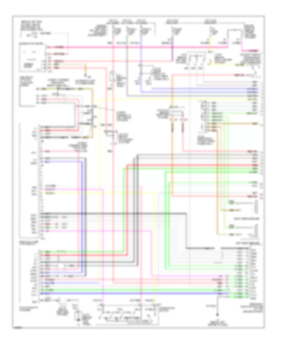 https://portal-diagnostov.com/license.html
Automotive Electricians Portal FZCO
Automotive Electricians Portal FZCO
https://portal-diagnostov.com/license.html
https://portal-diagnostov.com/license.html
Automotive Electricians Portal FZCO
Automotive Electricians Portal FZCOList of elements for 10-Speaker System Wiring Diagram, with Navigation (1 of 3) for Toyota 4Runner SR5 2004:
- (behind left end of dash, above driver side j/b) skid control ecu
- (center of liftgate) television camera
- (in body harness,
- (in body harness, in left side of liftgate)
- (in body harness, near top of left "d" pillar)
- (on rear of left cylinder head)
- (on right side of transmission) park/neutral position switch
- Acc
- Adpg
- Au1
- Au2
- C10
- C13
- Ca+
- Combination meter
- Combination switch
- Dome fuse 10a
- Driver side j/b (behind lower left end of dash)
- Dvd automatic changer
- Eau
- Engine room r/b (on left side of engine compartment)
- Gauge fuse 7.5a
- Gnd
- H j8
- Hot at all times
- Hot in on or start
- Ig1 fuse 15a
- Ih (behind left center of dash)
- J/c 25 (behind right center of dash)
- J/c 33 & 34 (behind right end of dash)
- J/c 33 (behind right end of dash)
- J/c 37 (behind right kick panel)
- J/c 42 (near front of right rear wheelwell)
- J/c 6 (behind left end of dash) c
- J/c 7 (behind left end of dash)
- J/c 8 & 9 (behind instrument cluster)
- J33
- J34
- J9 f
- K11
- Left rear speaker
- Lmut
- Mode
- Mute
- Nca
- Near right rear wheelwell)
- Ntsc
- Pnk
- R10
- Radio & player with display
- Radio 1 fuse 20a
- Radio 2 fuse 20a
- Rear seat audio controller (at top center of roof)
- Red
- Right rear speaker
- Rmu
- Rmut
- Rsl+
- Rsl-
- Rsr+
- Rsr-
- Seek+
- Seek-
- Sgnd
- Sld
- Sld1
- Sld2
- Sp1
- Speedo- meter
- Sw1
- Sw2
- Tx+
- Tx-
- Tx1+
- Tx1-
- Txl+
- Txl-
- Va-
- Val+
- Vol+
- Vol-
10-Speaker System Wiring Diagram, with Navigation (2 of 3) for Toyota 4Runner SR5 2004
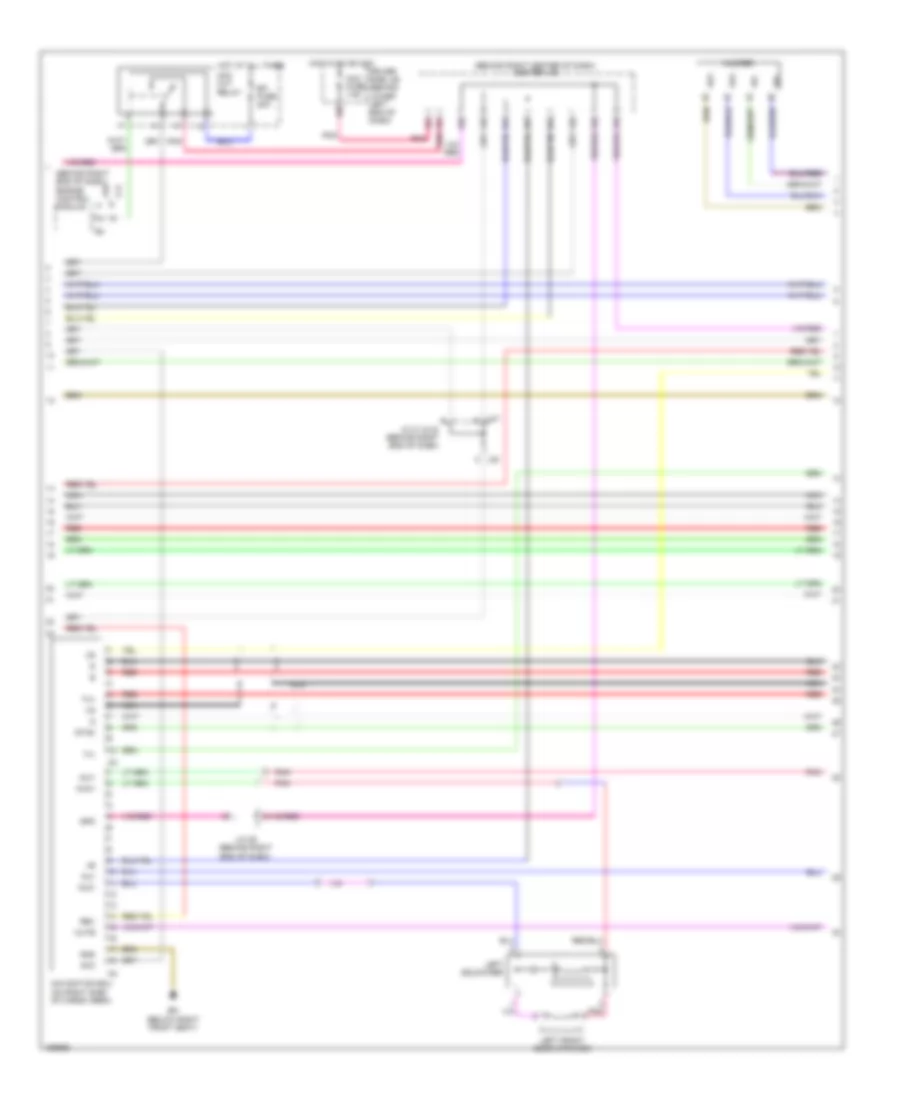 https://portal-diagnostov.com/license.html
Automotive Electricians Portal FZCO
Automotive Electricians Portal FZCO
https://portal-diagnostov.com/license.html
https://portal-diagnostov.com/license.html
Automotive Electricians Portal FZCO
Automotive Electricians Portal FZCOList of elements for 10-Speaker System Wiring Diagram, with Navigation (2 of 3) for Toyota 4Runner SR5 2004:
- (behind right center of dash) center j/b
- (behind right end of dash) engine control module
- 4.0l
- 4.7l
- Acc
- Acc cut relay
- Acc fuse 7.5a
- Aui+
- Aui-
- Auo+
- Auo-
- Bm (below right front seat)
- Driver side j/b (behind lower left end of dash)
- Efi fuse 20a
- Gnd
- Hot at all times
- Hot in on or acc
- J/c 29 (behind right end of dash)
- J/c 31 & 32 (behind right end of dash)
- J31
- J32 c
- Left front door speaker
- Left squawker
- Mute
- Navigation ecu (on right side of cargo area)
- Nca
- Pnk
- Red
- Rev
- Spd
- Sync
- Tx+
- Tx-
- Wf+
- Wf-
- Woofer
10-Speaker System Wiring Diagram, with Navigation (3 of 3) for Toyota 4Runner SR5 2004
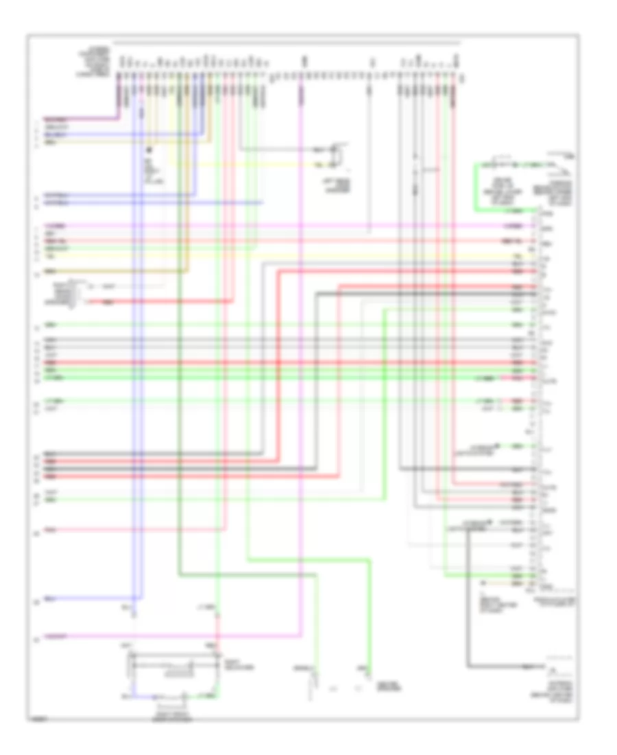 https://portal-diagnostov.com/license.html
Automotive Electricians Portal FZCO
Automotive Electricians Portal FZCO
https://portal-diagnostov.com/license.html
https://portal-diagnostov.com/license.html
Automotive Electricians Portal FZCO
Automotive Electricians Portal FZCOList of elements for 10-Speaker System Wiring Diagram, with Navigation (3 of 3) for Toyota 4Runner SR5 2004:
- +b2
- Acc
- Ant
- Antenna amplifier (behind center of dash)
- Bp (on right ``d" pillar)
- Center speaker
- Csp+
- Csp-
- Driver side j/b (behind lower left end of dash)
- Fl+
- Fl-
- Fr+
- Fr-
- Gnd
- Ij (behind right center of dash)
- Ill+
- Ill-
- Interior lights system
- J20
- Left rear door speaker
- Mute
- N-mu
- Nca
- Nca nca
- Parking brake switch (behind upper left end of dash)
- Pkb
- Pnk
- R11
- R12
- Radio & player with display
- Red
- Red red
- Rev
- Right front door speaker
- Right rear door speaker
- Right squawker
- Rl+
- Rl-
- Rr+
- Rr-
- Rs+
- Rs-
- S22
- S23
- Sgnd
- Sld
- Spd
- Stereo component amplifier (on right side of cargo area)
- Sync
- Tx+
- Tx-
- Wfl+
- Wfl-
- Wfr+
- Wfr-
10-Speaker System Wiring Diagram, without Navigation (1 of 2) for Toyota 4Runner SR5 2004
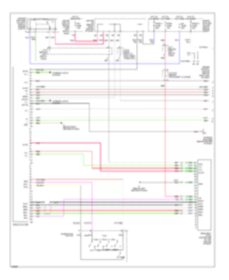 https://portal-diagnostov.com/license.html
Automotive Electricians Portal FZCO
Automotive Electricians Portal FZCO
https://portal-diagnostov.com/license.html
https://portal-diagnostov.com/license.html
Automotive Electricians Portal FZCO
Automotive Electricians Portal FZCOList of elements for 10-Speaker System Wiring Diagram, without Navigation (1 of 2) for Toyota 4Runner SR5 2004:
- (behind left center of dash)
- 4.0l 4.7l
- Acc
- Acc cut relay
- Acc fuse 7.5a
- Acc+b
- Ant+b
- Antenna amplifier (behind center of dash)
- Au1
- Au2
- Bu+b
- C13
- Center j/b (behind right center of dash)
- Combination switch
- Dome fuse 10a
- Driver side j/b (behind lower left end of dash)
- Eau
- Efi fuse 20a
- Engine control module (behind right end of dash)
- Engine room r/b (on left side of engine compt)
- F j9
- Gnd
- H j8
- Hot at all times
- Hot in acc or on
- Ij (behind right center of dash)
- Ill+
- Ill-
- Interior lights system
- J/c 42 (near front of right rear wheelwell)
- J/c 6 (behind left end of dash)
- J/c 7 (behind left end of dash)
- J/c 8 & 9 (behind instrument cluster)
- Mode
- Mute
- Nca
- Pnk
- Radio & player
- Radio 1 fuse 20a
- Radio 2 fuse 20a
- Rear seat audio controller (at top center of roof)
- Red
- Rmu
- Rmut
- Rsl+
- Rsl-
- Rsr+
- Rsr-
- Seek+
- Seek-
- Sgnd
- Sld
- Sld1
- Sw1
- Sw2
- Tx+
- Tx-
- Vol+
- Vol-
10-Speaker System Wiring Diagram, without Navigation (2 of 2) for Toyota 4Runner SR5 2004
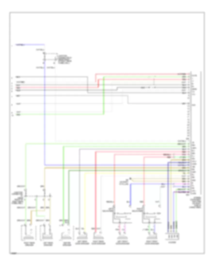 https://portal-diagnostov.com/license.html
Automotive Electricians Portal FZCO
Automotive Electricians Portal FZCO
https://portal-diagnostov.com/license.html
https://portal-diagnostov.com/license.html
Automotive Electricians Portal FZCO
Automotive Electricians Portal FZCOList of elements for 10-Speaker System Wiring Diagram, without Navigation (2 of 2) for Toyota 4Runner SR5 2004:
- +b2
- Acc
- Bp (on right ``d" pillar)
- Center speaker
- Csp+
- Csp-
- Fl+
- Fl-
- Fr+
- Fr-
- Gnd
- Junction connector (near front of right rear wheelwell)
- Junction connector 42 (near front of right rear wheelwell)
- Left front door speaker
- Left rear door speaker
- Left rear speaker
- Left squawker
- Mute
- Nca
- Pnk
- Red
- Right front door speaker
- Right rear door speaker
- Right rear speaker
- Right squawker
- Rl+
- Rl-
- Rr+
- Rr-
- Rs+
- Rs-
- S22
- S23
- Sgnd
- Stereo component amplifier (on right side of cargo area)
- Tx+
- Tx-
- Wf+
- Wf-
- Wfl+
- Wfl-
- Wfr+
- Wfr-
- Woofer
6-Speaker System Wiring Diagram, without Navigation for Toyota 4Runner SR5 2004
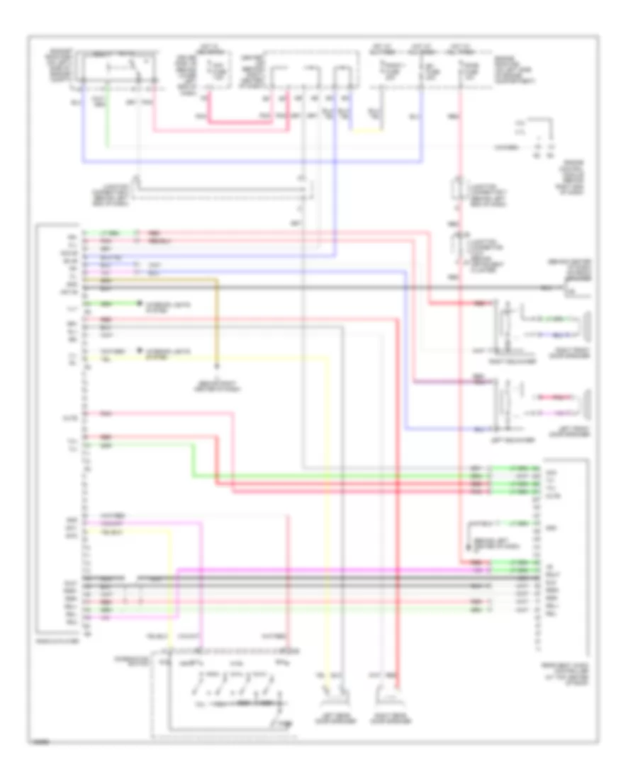 https://portal-diagnostov.com/license.html
Automotive Electricians Portal FZCO
Automotive Electricians Portal FZCO
https://portal-diagnostov.com/license.html
https://portal-diagnostov.com/license.html
Automotive Electricians Portal FZCO
Automotive Electricians Portal FZCOList of elements for 6-Speaker System Wiring Diagram, without Navigation for Toyota 4Runner SR5 2004:
- (behind center of dash) antenna amplifier
- (behind left center of dash) ih
- 4.0l
- 4.7l
- Acc
- Acc cut relay
- Acc fuse 7.5a
- Acc+b
- Ant+b
- Au1
- Au2
- Bu+b
- C13
- Center j/b (behind right center of dash)
- Combination switch
- Dome fuse 10a
- Driver side j/b (behind lower left end of dash)
- Eau
- Efi fuse 20a
- Engine control module (behind right end of dash)
- Engine room r/b (on left side of engine compartment)
- Engine room r/b (on left side of engine compt)
- F j9
- Fl+
- Fl-
- Fr+
- Fr-
- Gnd
- H j8
- Hot at all times
- Hot in acc or on
- Ij (behind right center of dash)
- Ill+
- Ill-
- Interior lights system
- Junction connector 6 (behind left end of dash)
- Junction connector 7 (behind left end of dash)
- Junction connector 8 & 9 (behind instrument cluster)
- Left front door speaker
- Left rear door speaker
- Left squawker
- Mode
- Mute
- Nca
- Pnk
- Radio & player
- Radio 1 fuse 20a
- Rear seat audio controller (at top center of roof)
- Red
- Right front door speaker
- Right rear door speaker
- Right squawker
- Rl+
- Rl-
- Rmu
- Rmut
- Rr+
- Rr-
- Rsl+
- Rsl-
- Rsr+
- Rsr-
- Seek+
- Seek-
- Sld
- Sld1
- Sw1
- Sw2
- Tx+
- Tx-
- Vol+
- Vol-
SHIFT INTERLOCK
Shift Interlock Wiring Diagram for Toyota 4Runner SR5 2004
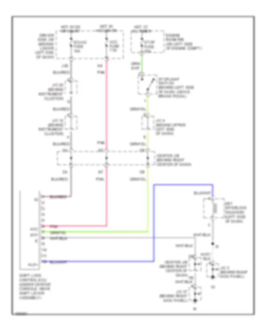 https://portal-diagnostov.com/license.html
Automotive Electricians Portal FZCO
Automotive Electricians Portal FZCO
https://portal-diagnostov.com/license.html
https://portal-diagnostov.com/license.html
Automotive Electricians Portal FZCO
Automotive Electricians Portal FZCOList of elements for Shift Interlock Wiring Diagram for Toyota 4Runner SR5 2004:
- Acc
- Acc fuse 7.5a
- Center j/b (behind right center of dash)
- Driver side j/b (behind lower left end of dash)
- Ecu-ig fuse 10a
- Engine room r/b (on left side of engine compt)
- Hot at all times
- Hot in acc or on
- Hot in on or start
- J/c 12 (behind instrument cluster)
- J/c 20 (behind instrument cluster)
- J/c 37 (behind right kick panel)
- J/c 4 (behind upper left end of dash)
- J/c 5 (behind right kick panel)
- J28
- Key interlock solenoid (left side of dash)
- Kls+
- Pnk
- Shift lock control ecu (under center console, near shift lever assembly)
- Stop fuse 10a
- Stoplight switch (behind left side of dash, above brake pedal)
- Stp
STARTING/CHARGING
Charging Wiring Diagram for Toyota 4Runner SR5 2004
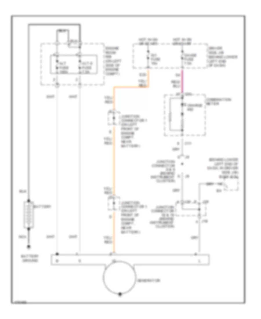 https://portal-diagnostov.com/license.html
Automotive Electricians Portal FZCO
Automotive Electricians Portal FZCO
https://portal-diagnostov.com/license.html
https://portal-diagnostov.com/license.html
Automotive Electricians Portal FZCO
Automotive Electricians Portal FZCOList of elements for Charging Wiring Diagram for Toyota 4Runner SR5 2004:
- (behind lower left end of dash, in driver side j/b) body ecu
- Alt fuse 140a
- Alt-s fuse 7.5a
- Battery
- Battery ground
- C10
- C11
- Charge ind
- Combination meter
- Driver side j/b (behind lower left end of dash)
- E20
- Engine room r/b (on left side of engine compt)
- Gauge fuse 7.5a
- Generator
- Hot in on or start
- Ig1 fuse 15a
- J18
- J19
- Junction connector 1 (on left front of engine compt, near battery)
- Junction connector 18 & 19 (behind instrument cluster)
- Junction connector 8 & 9 (behind g instrument cluster)
- Nca
Starting Wiring Diagram for Toyota 4Runner SR5 2004
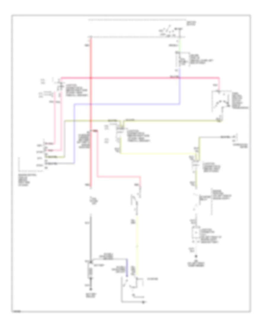 https://portal-diagnostov.com/license.html
Automotive Electricians Portal FZCO
Automotive Electricians Portal FZCO
https://portal-diagnostov.com/license.html
https://portal-diagnostov.com/license.html
Automotive Electricians Portal FZCO
Automotive Electricians Portal FZCOList of elements for Starting Wiring Diagram for Toyota 4Runner SR5 2004:
- 4.0l
- 4.7l
- A d
- Acc
- Am2 fuse 30a
- Battery
- Battery ground
- Combination meter
- Driver side j/b (behind lower left end of dash)
- E6 (in engine harness, between battery & engine room r/b)
- Eb (on left front inner fender)
- Engine control module (behind right end of dash)
- Engine room r/b (on left side of engine compt)
- Ignition switch
- Junction connector 2 & 3 (on left front of engine compt, j2 near battery)
- Junction connector 28 (behind right side of dash, near firewall grommet)
- Junction connector 35 (behind right end of dash)
- Lock
- N r
- Nca
- Nsw
- Off
- Park/ neutral position switch (on right side of p transmission)
- Pnk
- Red
- Sta
- Sta fuse 2 7.5a
- Star
- Start
- Starter
- Starter relay
- Stsw
SUPPLEMENTAL RESTRAINTS
Supplemental Restraints Wiring Diagram, with Side Airbag (1 of 2) for Toyota 4Runner SR5 2004
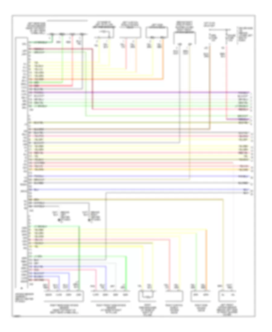 https://portal-diagnostov.com/license.html
Automotive Electricians Portal FZCO
Automotive Electricians Portal FZCO
https://portal-diagnostov.com/license.html
https://portal-diagnostov.com/license.html
Automotive Electricians Portal FZCO
Automotive Electricians Portal FZCOList of elements for Supplemental Restraints Wiring Diagram, with Side Airbag (1 of 2) for Toyota 4Runner SR5 2004:
- (at base of left "b" pillar) left pretensioner
- (behind left center of dash) ih
- (behind right center of dash) ij
- (behind right side of front bumper cover) right front air bag sensor
- +sl
- +sr
- -sl
- -sr
- A30
- A32
- A33
- Air bag sensor assembly (below center of dash)
- Csl+
- Csl-
- Csr+
- Csr-
- D2+
- D2-
- Driver side j/b (behind lower left end of dash)
- Escl
- Escr
- Esl
- Esr
- Gauge fuse 7.5a
- Gsw2
- Hot in on or start
- Icl+
- Icl-
- Icr+
- Icr-
- Ig2
- L20
- Lbe+
- Left curtain shield air bag squib
- Left front air bag sensor (behind left side of front bumper cover)
- Left rear side air bag sensor (near top front of left rear wheelwell)
- Left side air bag squib
- Lsp+
- Lsp-
- P2+
- P2-
- Pl+
- Pl-
- Pnk
- Pr+
- Pr-
- Rbe+
- Red
- Right curtain shield air bag squib
- Right front side air bag sensor (at base of right "b" pillar)
- Right pretensioner (at base of right "b" pillar)
- Right rear side air bag sensor (near top front of right rear wheelwell)
- Right side air bag squib
- Rmil
- Rmsw
- Sfl+
- Sfl-
- Sfr+
- Sfr-
- Sil
- Srs fuse 10a
- Ssl+
- Ssl-
- Ssr+
- Ssr-
- Vucl
- Vucr
- Vupl
- Vupr
Supplemental Restraints Wiring Diagram, with Side Airbag (2 of 2) for Toyota 4Runner SR5 2004
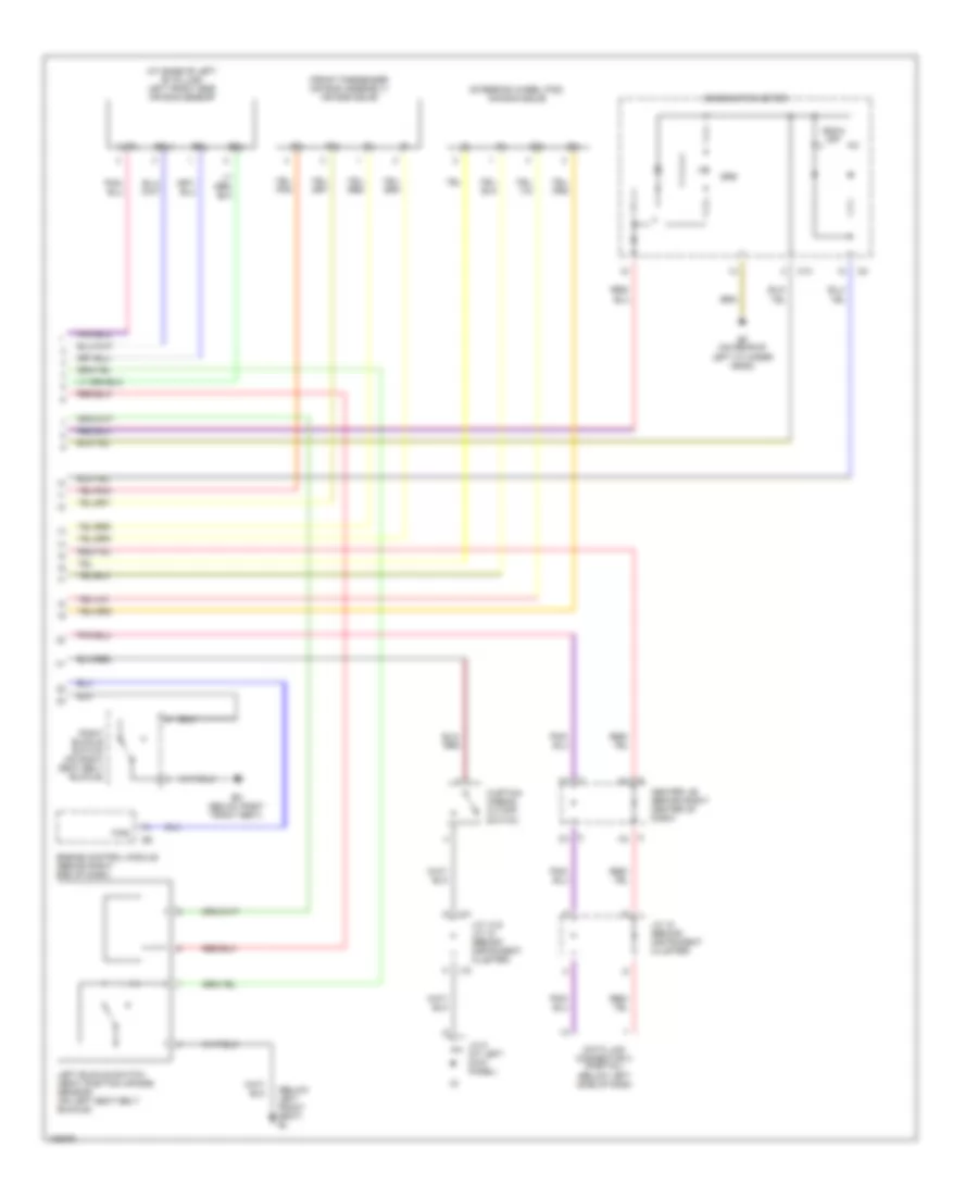 https://portal-diagnostov.com/license.html
Automotive Electricians Portal FZCO
Automotive Electricians Portal FZCO
https://portal-diagnostov.com/license.html
https://portal-diagnostov.com/license.html
Automotive Electricians Portal FZCO
Automotive Electricians Portal FZCOList of elements for Supplemental Restraints Wiring Diagram, with Side Airbag (2 of 2) for Toyota 4Runner SR5 2004:
- (at base of left "b" pillar) left front side air bag sensor
- (below left front seat) bl
- (front passenger air bag assembly) air bag squib
- (steering wheel pad) air bag squib
- Bm (below right front seat)
- C10
- Center j/b (behind right center of dash)
- Combination meter
- Curtain airbag cutoff switch
- D2+
- D2-
- Data link connector 3 (partial) (below left side of dash
- Ef (on rear of left cylinder head)
- Engine control module (behind right end of dash)
- Esl
- F/ps
- J/c 14 & j/c 15 (behind instrument cluster)
- J/c 18 (behind instrument cluster)
- J/c 5 (at left kick panel)
- J14
- J15
- Left buckle switch (seat position air bag sensor) (on left seat belt buckle)
- P2+
- P2-
- Right buckle switch (on right seat belt buckle)
- Rsca off
- Srs
- Ssl+
- Ssl-
- Vupl
Supplemental Restraints Wiring Diagram, without Side Airbag for Toyota 4Runner SR5 2004
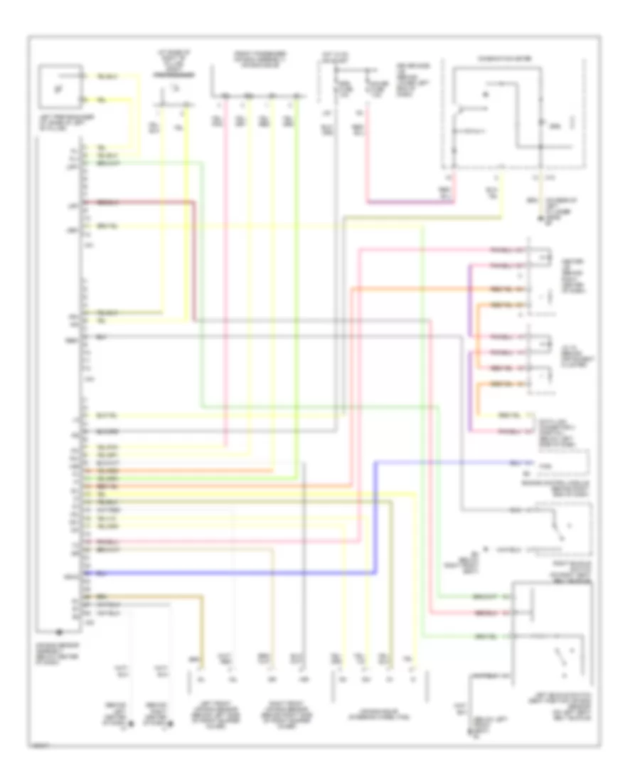 https://portal-diagnostov.com/license.html
Automotive Electricians Portal FZCO
Automotive Electricians Portal FZCO
https://portal-diagnostov.com/license.html
https://portal-diagnostov.com/license.html
Automotive Electricians Portal FZCO
Automotive Electricians Portal FZCOList of elements for Supplemental Restraints Wiring Diagram, without Side Airbag for Toyota 4Runner SR5 2004:
- (at base of right "b" pillar) right pretensioner
- (behind left center of dash) ih
- (behind right center of dash) ij
- (below left front seat) bl
- (front passenger air bag assembly) air bag squib
- (on rear of left cylinder head) ef
- +sl
- +sr
- -sl
- -sr
- A31
- A32
- A34
- Air bag sensor assembly (below center of dash)
- Air bag squib (steering wheel pad)
- Bm (below right front seat)
- C10
- Center j/b (behind right center of dash)
- Combination meter
- D2+
- D2-
- Data link connector 3 (partial) (below left side of dash)
- Driver side j/b (behind lower left end of dash)
- Engine control module (behind right end of dash)
- F/ps
- Gauge fuse 7.5a
- Gsw2
- Hot in on or start
- Ig2
- J/c 18 (behind instrument cluster)
- L20
- Lbe+
- Left buckle switch (seat position air bag sensor) (on left seat belt buckle)
- Left front air bag sensor (behind left side of front bumper cover)
- Left pretensioner (at base of left "b" pillar)
- Lsp+
- Lsp-
- P2+
- P2-
- Pl+
- Pl-
- Pr+
- Pr-
- Rbe+
- Right buckle switch (on right seat belt buckle)
- Right front air bag sensor (behind right side of front bumper cover)
- Sil
- Srs
- Srs fuse 10a
TRANSMISSION
4.0L
4.0L, 4WD Wiring Diagram for Toyota 4Runner SR5 2004
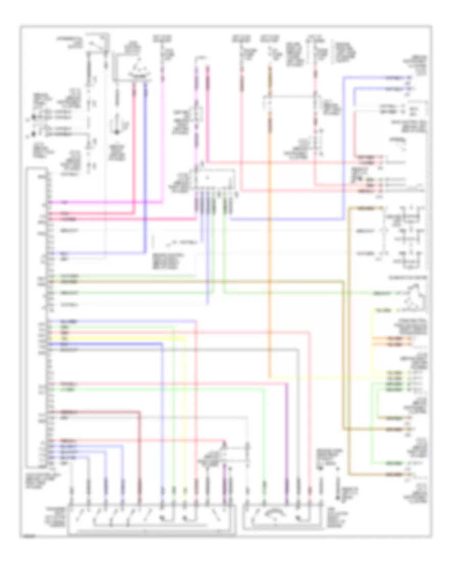 https://portal-diagnostov.com/license.html
Automotive Electricians Portal FZCO
Automotive Electricians Portal FZCO
https://portal-diagnostov.com/license.html
https://portal-diagnostov.com/license.html
Automotive Electricians Portal FZCO
Automotive Electricians Portal FZCOList of elements for 4.0L, 4WD Wiring Diagram for Toyota 4Runner SR5 2004:
- (behind instrument cluster) j/c 20, j/c 21
- (behind left kick panel) j/c 5
- (engine harn, near rear of right cyl head) e12
- (rear of left cyl head) ef
- 2-4
- 4lo
- 4wd
- 4wd control ecu (behind lower right end of dash)
- 4wd control switch
- 4wd fuse 20a
- Add
- Add actuator (right front of engine)
- C10
- C11
- Center diff lock
- Center j/b (behind right center of dash)
- Combination meter
- Differential lock switch
- Dl1
- Dl2
- Dm1
- Dm2
- Dome fuse 10a
- Driver side j/b (behind lower left end of dash)
- Engine control module (ecm) (behind right end of dash)
- Engine room r/b (left side of engine compt)
- Exi4
- F10
- Gauge fuse 7.5a
- Gnd
- Hl1
- Hl2
- Hm1
- Hm2
- Hot at all times
- Hot in on or start
- Ig1 fuse 15a
- Ii (behind right center of dash)
- Ind1
- Ind2
- Ind3
- J/c
- J/c 10, j/c 11 (behind instrument cluster)
- J/c 14, j/c 15 (behind instrument cluster)
- J/c 20 (behind instrument cluster)
- J/c 25 (behind right center of dash)
- J/c 28 (behind right side of dash) b
- J/c 29, j/c 30 (behind right end of dash)
- J/c 31, j/c 32 (behind right end of dash)
- J/c 33, j/c 34 (behind right end of dash)
- J/c 37 (behind right kick panel)
- J/c 7 (behind left end of dash)
- J/c 8, j/c 9 (behind instrument cluster)
- J10
- J11
- J13
- J14
- J15
- J20
- J21
- J29
- J30
- J31
- J32
- J33
- J34
- K11
- Park/neutral position switch (right side of transmission)
- Pnk
- Red
- Skid control ecu (behind left end of dash)
- Sp1
- Spd
- Speedo
- Tl1
- Tl2
- Tl3
- Tm1
- Tm2
- Transfer shift actuator (on trans- mission)
4.0L, A/T Wiring Diagram (1 of 3) for Toyota 4Runner SR5 2004
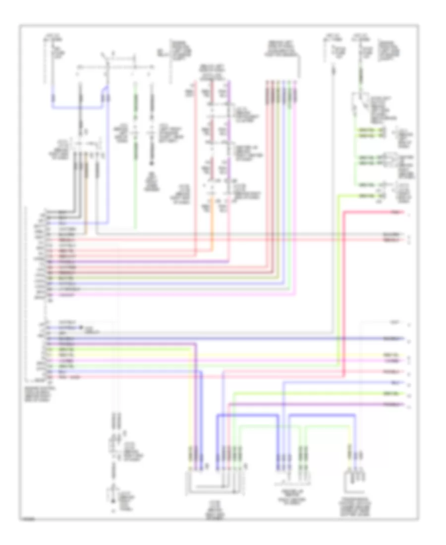 https://portal-diagnostov.com/license.html
Automotive Electricians Portal FZCO
Automotive Electricians Portal FZCO
https://portal-diagnostov.com/license.html
https://portal-diagnostov.com/license.html
Automotive Electricians Portal FZCO
Automotive Electricians Portal FZCOList of elements for 4.0L, A/T Wiring Diagram (1 of 3) for Toyota 4Runner SR5 2004:
- (4wd)
- (behind left side of dash) accelerator position sensor
- (below left side of dash)
- +b1
- +bm
- 4wd circuit
- At3
- Atd
- Batt
- Center j/b (behind
- Center j/b (behind right center of dash)
- Data link connector 3
- Eb (left front inner fender)
- Efi fuse 20a
- Efi relay
- Engine control module (ecm) (behind right end of dash)
- Engine room r/b (left side of engine compt)
- Eom
- Epa
- Epa2
- Etcs fuse 10a
- Hot at all times
- Igsw
- J/c 18 (behind instrument cluster)
- J/c 2 (left front of engine compt, near battery)
- J/c 29, j/c 30 (behind
- J/c 29, j/c 30 (behind right end of dash)
- J/c 31, j/c 32 (behind right end of dash)
- J/c 31, j/c 32 (right end of dash)
- J/c 33, j/c 34 (behind right end of dash)
- J/c 35, j/c 36 (behind right end of dash)
- J/c 37 (behind right kick panel)
- J/c 4 (behind left end of dash)
- J29
- J29 e
- J30
- J30 a
- J31
- J32
- J33
- J34
- J35 f
- J36 h
- Mil
- Mrel
- Nssd
- Oilw
- Pnk
- Right center of dash)
- Right end of dash)
- Sil
- Spd
- Stop fuse 10a
- Stoplight switch (behind left sdie of dash, above brake pedal)
- Stp
- Transmission control switch (under center console, near shifter lever)
- Vcp2
- Vcpa
- Vpa
- Vpa2
- Wfse
4.0L, A/T Wiring Diagram (2 of 3) for Toyota 4Runner SR5 2004
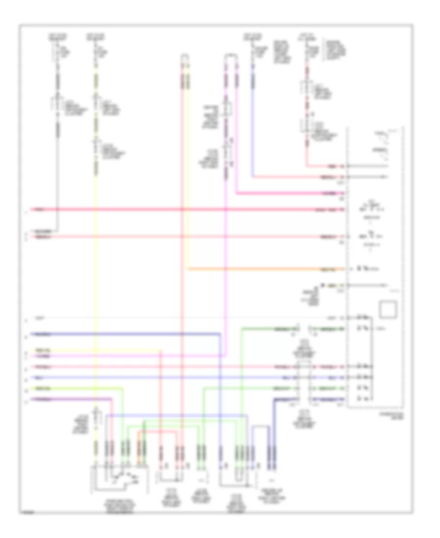 https://portal-diagnostov.com/license.html
Automotive Electricians Portal FZCO
Automotive Electricians Portal FZCO
https://portal-diagnostov.com/license.html
https://portal-diagnostov.com/license.html
Automotive Electricians Portal FZCO
Automotive Electricians Portal FZCOList of elements for 4.0L, A/T Wiring Diagram (2 of 3) for Toyota 4Runner SR5 2004:
- (4wd)
- A/t oil temp
- C10
- C11
- Center j/b (behind right center of dash)
- Cluster)
- Combination meter
- Dome fuse 10a
- Driver side j/b (behind lower left end of dash)
- Ef (rear of left cylinder head)
- Engine room r/b (left side of engine compt)
- Gauge fuse 7.5a
- Hot at all times
- Hot in on or start
- Ig1 fuse 15a
- Ign fuse 10a
- Instrument cluster)
- J/c 10, j/c 11 (behind
- J/c 20 (behind instrument cluster)
- J/c 25 (behind right center of dash)
- J/c 29 (behind right end of dash)
- J/c 29, j/c 30 (behind right end of dash)
- J/c 33, j/c 34 (behind
- J/c 35, j/c 36 (behind right end of dash)
- J/c 7 (behind left end of dash)
- J/c 8 (behind instrument cluster)
- J/c 8, j/c 9 (behind
- J/c 8, j/c 9 (behind instrument j9
- J10
- J11
- J29
- J30
- J33
- J34
- J35
- J36
- K11
- Mil
- Park/neutral position switch (right side of transmission)
- Pnk
- Red
- Right end of dash)
- Speedo
- Tach
4.0L, A/T Wiring Diagram (3 of 3) for Toyota 4Runner SR5 2004
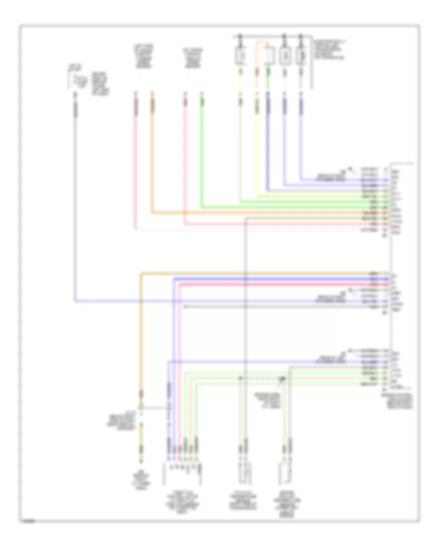 https://portal-diagnostov.com/license.html
Automotive Electricians Portal FZCO
Automotive Electricians Portal FZCO
https://portal-diagnostov.com/license.html
https://portal-diagnostov.com/license.html
Automotive Electricians Portal FZCO
Automotive Electricians Portal FZCOList of elements for 4.0L, A/T Wiring Diagram (3 of 3) for Toyota 4Runner SR5 2004:
- (engine harn, near front of right cyl head)
- (left side of trans- mission) turbine speed sensor
- (on trans- mission) vehicle speed sensor
- A/t fluid temperature sensor (right side of transmission)
- Driver side j/b (behind lower left end of dash)
- E01
- E02
- E03
- E04
- E05
- Ee (rear of right cylinder head)
- Ef (rear of left cylinder head)
- Electronically controlled transmission solenoid (on transaxle)
- Engine control module (ecm) (behind right end of dash)
- Engine coolant temperature sensor (upper left side of engine)
- Ge01
- Grommet)
- Hot in start
- J/c 27 (behind right side of dash, near firewall c
- Me01
- Nca
- Nco+
- Nco-
- Pnk
- Red
- Slt+
- Slt-
- Sp2+
- Sp2-
- Sta 2 fuse 7.5a
- Stsw
- Thoc
- Throttle control motor & throttle position sensor (on throttle body)
- Thw
- Vta1
- Vta2
4.7L
4.7L, 4WD Wiring Diagram for Toyota 4Runner SR5 2004
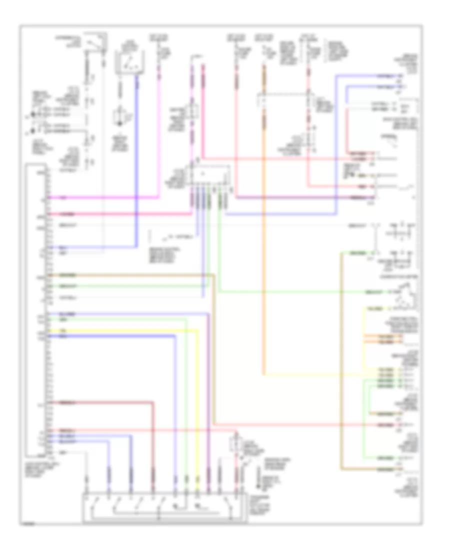 https://portal-diagnostov.com/license.html
Automotive Electricians Portal FZCO
Automotive Electricians Portal FZCO
https://portal-diagnostov.com/license.html
https://portal-diagnostov.com/license.html
Automotive Electricians Portal FZCO
Automotive Electricians Portal FZCOList of elements for 4.7L, 4WD Wiring Diagram for Toyota 4Runner SR5 2004:
- (behind instrument cluster) j/c 20, j/c 21
- (behind left kick panel) j/c 5
- (engine harn, near rear of engine)
- (rear of left cyl head) ef
- (rear of right cyl head) ee
- 4lo
- 4wd control ecu (behind lower right end of dash)
- 4wd control switch
- 4wd fuse 20a
- C10
- C11
- Center diff lock
- Center j/b (behind right center of dash)
- Combination meter
- Differential lock switch
- Dome fuse 10a
- Driver side j/b (behind lower left end of dash)
- Engine control module (ecm) (behind right end of dash)
- Engine room r/b (left side of engine compt)
- Exi4
- F10
- Gauge fuse 7.5a
- Gnd
- Hl1
- Hl2
- Hm1
- Hm2
- Hot at all times
- Hot in on or start
- Ig1 fuse 15a
- Ii (behind right center of dash)
- Ind2
- Ind3
- J/c
- J/c 10, j/c 11 (behind instrument cluster)
- J/c 14, j/c 15 (behind instrument cluster)
- J/c 20 (behind instrument cluster)
- J/c 25 (behind right center of dash)
- J/c 28 (behind right side of dash)
- J/c 29, j/c 30 (behind right end of dash)
- J/c 31, j/c 32 (behind right end of dash)
- J/c 33, j/c 34 (behind right end of dash)
- J/c 37 (behind right kick panel)
- J/c 7 (behind left end of dash)
- J/c 8, j/c 9 (behind instrument cluster)
- J10
- J11
- J13
- J14
- J15
- J20
- J21
- J29
- J30
- J31
- J32
- J33
- J34
- K11
- Park/neutral position switch (right side of transmission)
- Red
- Skid control ecu (behind left end of dash)
- Sp1
- Spd
- Speedo
- Tl2
- Tl3
- Tm1
- Tm2
- Transfer shift actuator (on trans- mission)
4.7L, A/T Wiring Diagram (1 of 3) for Toyota 4Runner SR5 2004
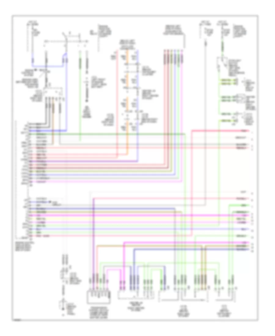 https://portal-diagnostov.com/license.html
Automotive Electricians Portal FZCO
Automotive Electricians Portal FZCO
https://portal-diagnostov.com/license.html
https://portal-diagnostov.com/license.html
Automotive Electricians Portal FZCO
Automotive Electricians Portal FZCOList of elements for 4.7L, A/T Wiring Diagram (1 of 3) for Toyota 4Runner SR5 2004:
- (4wd)
- (behind left side of dash) accelerator position sensor
- (below left side of dash)
- (engine harn, between battery and engine room j/b)
- +b1
- +bm
- 4wd circuit
- A j30
- At2
- At4
- Atd
- Atl
- Batt
- Center j/b (behind
- Center j/b (behind right center of dash)
- Data link connector 3
- E j29
- Eb (left front inner fender)
- Efi fuse 20a
- Efi relay
- Engine control module (ecm) (behind right end of dash)
- Engine controls system
- Engine room r/b (left side of engine compt)
- Eom
- Epa
- Epa2
- Etcs fuse 10a
- Hot at all times
- Igsw
- Instrument cluster)
- J/c 18 (behind instrument cluster)
- J/c 2 (left front of engine compt, near battery)
- J/c 29, j/c 30 (behind right end of dash)
- J/c 31, j/c 32 (behind right end of dash)
- J/c 31, j/c 32 (right end of dash)
- J/c 33, j/c 34 (behind right end of dash)
- J/c 35, j/c 36 (behind
- J/c 35, j/c 36 (behind right end of dash)
- J/c 37 (behind right kick panel)
- J/c 4 (behind left end of dash)
- J/c 8, j/c 9 (behind
- J31
- J32
- J33
- J34
- J35
- J35 f
- J36
- J36 h
- Mil
- Mrel
- Nssd
- Nssl
- Oilw
- Pnk
- Right center of dash)
- Right end of dash)
- Sil
- Spd
- Stop fuse 10a
- Stoplight switch (behind left sdie of dash, above brake pedal)
- Stp
- Transmission control switch (under center console, near shifter lever)
- Vcp2
- Vcpa
- Vpa
- Vpa2
- Wfse
4.7L, A/T Wiring Diagram (2 of 3) for Toyota 4Runner SR5 2004
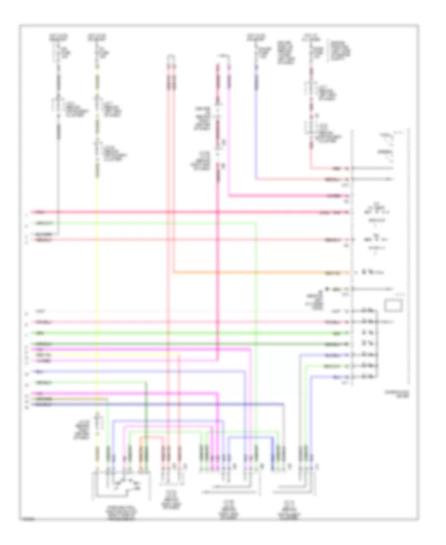 https://portal-diagnostov.com/license.html
Automotive Electricians Portal FZCO
Automotive Electricians Portal FZCO
https://portal-diagnostov.com/license.html
https://portal-diagnostov.com/license.html
Automotive Electricians Portal FZCO
Automotive Electricians Portal FZCOList of elements for 4.7L, A/T Wiring Diagram (2 of 3) for Toyota 4Runner SR5 2004:
- (4wd)
- A/t oil temp
- C10
- C11
- Center j/b (behind right center of dash)
- Cluster)
- Combination meter
- Dome fuse 10a
- Driver side j/b (behind lower left end of dash)
- Ef (rear of left cylinder head)
- Engine room r/b (left side of engine compt)
- Gauge fuse 7.5a
- Hot at all times
- Hot in on or start
- Ig1 fuse 15a
- Ign fuse 10a
- Instrument cluster)
- J/c 10, j/c 11 (behind
- J/c 20 (behind instrument cluster)
- J/c 25 (behind right center of dash)
- J/c 29, j/c 30 (behind
- J/c 29, j/c 30 (behind right end of dash)
- J/c 33, j/c 34 (behind
- J/c 7 (behind left end of dash)
- J/c 8 (behind instrument cluster)
- J/c 8, j/c 9 (behind instrument j9
- J10
- J11
- J29
- J30
- J33
- J34
- K11
- Mil
- Park/neutral position switch (right side of transmission)
- Pnk
- Red
- Right end of dash)
- Speedo
- Tach
4.7L, A/T Wiring Diagram (3 of 3) for Toyota 4Runner SR5 2004
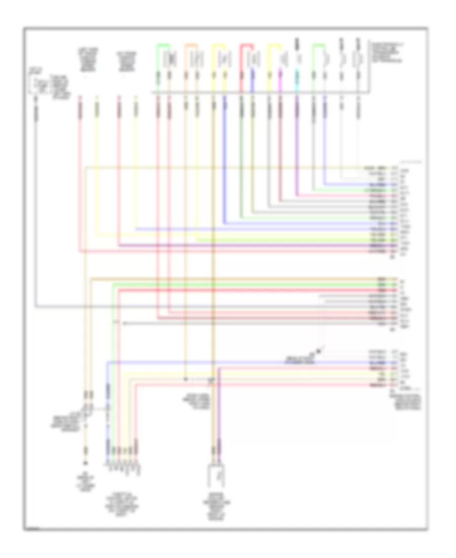 https://portal-diagnostov.com/license.html
Automotive Electricians Portal FZCO
Automotive Electricians Portal FZCO
https://portal-diagnostov.com/license.html
https://portal-diagnostov.com/license.html
Automotive Electricians Portal FZCO
Automotive Electricians Portal FZCOList of elements for 4.7L, A/T Wiring Diagram (3 of 3) for Toyota 4Runner SR5 2004:
- (4wd)
- (dash harn, behind upper right side of dash)
- (left side of trans- mission) turbine speed sensor
- (on trans- mission) vehicle speed sensor
- 4wd
- Driver side j/b (behind lower left end of dash)
- E01
- E02
- E03
- Ee (rear of right cylinder head)
- Ef (rear of left cylinder head)
- Electronically controlled transmission solenoid (on transaxle)
- Engine control module (ecm) (behind right end of dash)
- Engine coolant temperature sensor (right front of engine)
- Ge01
- Grommet)
- Hot in start
- J/c 26 (behind right side of dash, near firewall b
- Me01
- Nca
- Nt+
- Nt-
- Red
- Sl1+
- Sl1-
- Sl2+
- Sl2-
- Slt+
- Slt-
- Slu+
- Slu-
- Sp2+
- Sp2-
- Sta 2 fuse 7.5a
- Stsw
- Tho1
- Tho2
- Throttle control motor & throttle position sensor (on throttle body)
- Thw
- Vta1
- Vta2
WARNING SYSTEMS
Chime Wiring Diagram for Toyota 4Runner SR5 2004
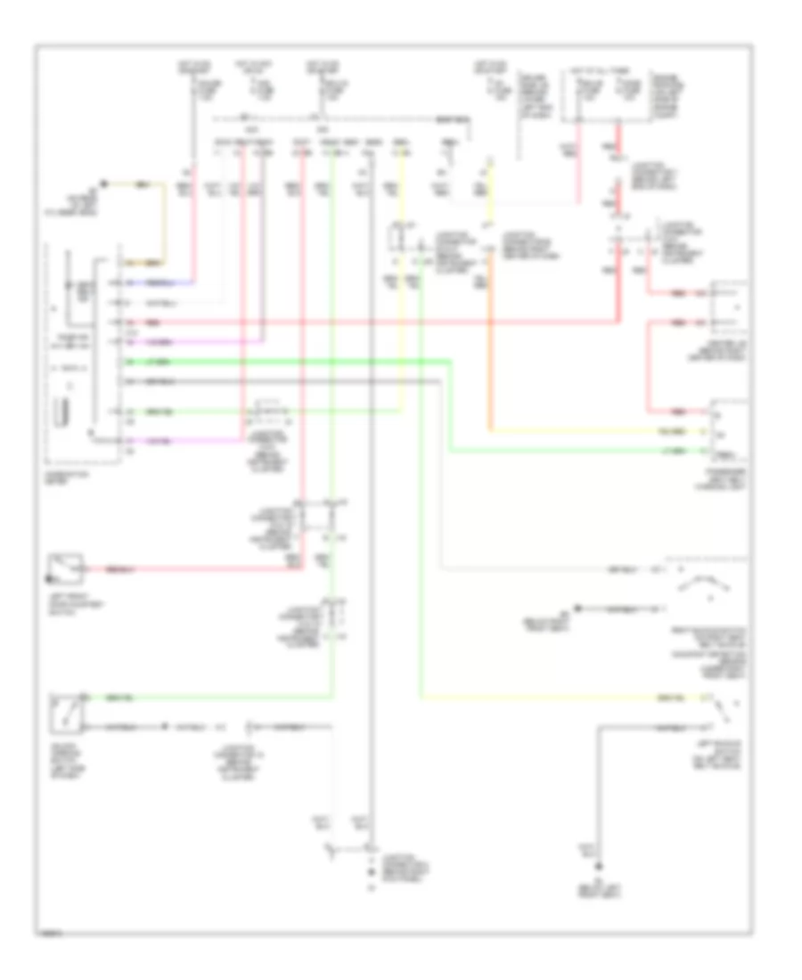 https://portal-diagnostov.com/license.html
Automotive Electricians Portal FZCO
Automotive Electricians Portal FZCO
https://portal-diagnostov.com/license.html
https://portal-diagnostov.com/license.html
Automotive Electricians Portal FZCO
Automotive Electricians Portal FZCOList of elements for Chime Wiring Diagram for Toyota 4Runner SR5 2004:
- (behind instrument cluster)
- Acc
- Acc fuse 7.5a
- B j14
- Becu
- Bl (below left front seat)
- Bm (below right front seat)
- Body ecu
- Buzzer
- C j15
- C10
- Center j/b (behind right center of dash)
- Combination meter
- Dbkl
- Dcty
- Dcy2
- Dome fuse 10a
- Door courtesy
- Door ind
- Driver side j/b (behind lower left end of dash)
- Drlp
- Ecu-b fuse 10a
- Ecu-ig fuse 10a
- Ef (on rear of left cylinder head)
- Engine room r/b (on left side of engine compt)
- Gauge fuse 7.5a
- Gnd1
- Gnd2
- Hot at all times
- Hot in acc or on
- Hot in on or start
- Ig+
- Ig1 fuse 15a
- J18 e
- J19
- J20 d
- J21
- Junction connector 14 & 15 (behind instrument cluster)
- Junction connector 15 (behind instrument cluster)
- Junction connector 18 & 19 (behind instrument cluster)
- Junction connector 20 & 21 (behind instrument cluster)
- Junction connector 25 (behind right center of dash)
- Junction connector 5 (behind right kick panel)
- Junction connector 7 (behind left end of dash)
- Junction connector 8 & 9
- Junction connector 8 & 9 (behind instrument cluster)
- Kswo
- Left buckle switch (on left seat belt buckle)
- Left front
- Occupant detection sensor (under right front seat)
- Passenger seat belt warning light
- Pbew
- Red
- Right buckle switch (on right seat belt buckle)
- Seat belt ind
- Sig
- Switch
- Unlock warning switch (left side of dash)
Tire Pressure Monitoring Wiring Diagram for Toyota 4Runner SR5 2004
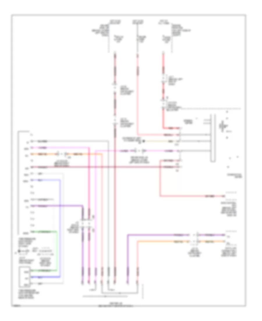 https://portal-diagnostov.com/license.html
Automotive Electricians Portal FZCO
Automotive Electricians Portal FZCO
https://portal-diagnostov.com/license.html
https://portal-diagnostov.com/license.html
Automotive Electricians Portal FZCO
Automotive Electricians Portal FZCOList of elements for Tire Pressure Monitoring Wiring Diagram for Toyota 4Runner SR5 2004:
- (on rear of left cylinder head) ef
- +5v
- C10
- Center j/b (behind right center of dash)
- Combination
- Data link connector 3 (below left side of dash)
- Dome fuse 10a
- Driver side j/b (behind lower left end of dash)
- Ecu-ig fuse 10a
- Engine room r/b (on left side of engine compt)
- Gauge fuse 7.5a
- Gnd
- Gnd2
- Hot at all times
- Hot in on or start
- Ind
- J/c 12 (behind instrument cluster)
- J/c 18 (behind instrument cluster)
- J/c 20 (behind instrument cluster)
- J/c 29 & 30 (behind right end of dash)
- J/c 33 & 34 (behind right end of dash)
- J/c 35 & 36 (behind right end of dash)
- J/c 37 (behind right kick panel)
- J/c 7 (behind left end of dash)
- J/c 8 & 9 (behind instrument cluster)
- J28
- J29
- J30
- J33
- J34
- J35
- K11
- Meter
- Pressure tire
- Rda
- Red
- Rf5v
- Sil
- Skid control ecu (behind left end of dash, above driver side j/b)
- Spd
- Speedo -meter
- Tire pressure monitor ecu (right side of dash)
- Tire pressure monitor receiver (top center rear of roof)
WIPER/WASHER
Front Wiper/Washer Wiring Diagram for Toyota 4Runner SR5 2004
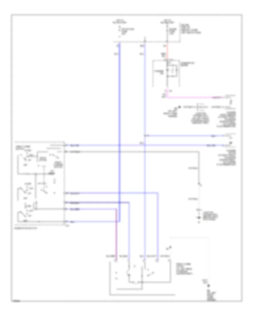 https://portal-diagnostov.com/license.html
Automotive Electricians Portal FZCO
Automotive Electricians Portal FZCO
https://portal-diagnostov.com/license.html
https://portal-diagnostov.com/license.html
Automotive Electricians Portal FZCO
Automotive Electricians Portal FZCOList of elements for Front Wiper/Washer Wiring Diagram for Toyota 4Runner SR5 2004:
- (at left rear of engine compartment)
- (behind lower
- (on left
- C10
- C14
- Combination meter
- Combination switch
- Driver side j/b
- E22
- Eb (on left front inner fender)
- Fender)
- Fr wip-wsh fuse 30a
- Front inner
- Front washer switch
- Front wiper motor
- Front wiper switch
- Gauge fuse 7.5a
- High
- Hot in on or start
- Int
- Int time
- Junction connector 2 (on left front of engine compt, near battery)
- Junction connector 5 (behind right kick panel)
- Left end of dash)
- Low
- Off
- Red/
- Solid state
- Washer ind
- Washer level sensor (at right front of engine compartment, on washer fluid reservoir)
- Washer motor (at right front of engine compartment, on washer fluid reservoir)
Rear Washer/Wiper Wiring Diagram for Toyota 4Runner SR5 2004
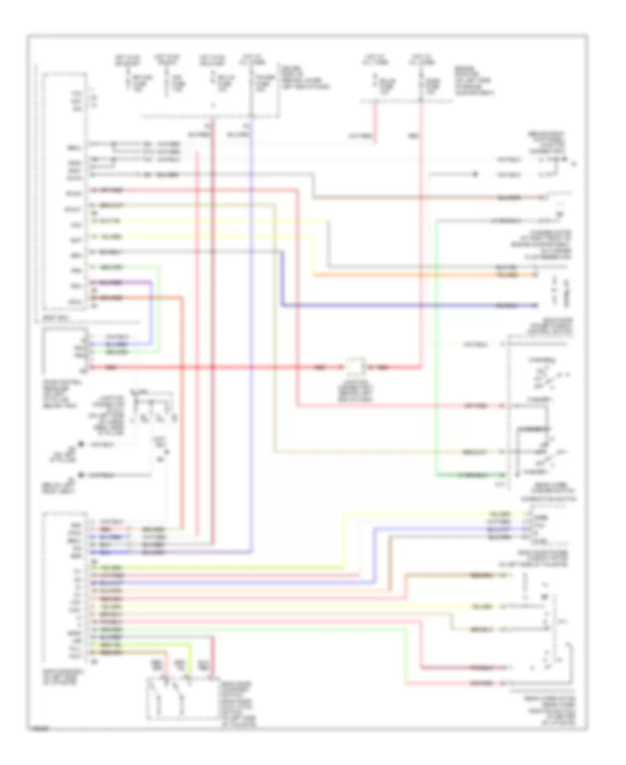 https://portal-diagnostov.com/license.html
Automotive Electricians Portal FZCO
Automotive Electricians Portal FZCO
https://portal-diagnostov.com/license.html
https://portal-diagnostov.com/license.html
Automotive Electricians Portal FZCO
Automotive Electricians Portal FZCOList of elements for Rear Washer/Wiper Wiring Diagram for Toyota 4Runner SR5 2004:
- (behind lower
- (behind right kick panel) junction connector 5
- (in center of liftgate)
- (on left side
- Acc
- Acc fuse 7.5a
- Back door courtesy switch, back door half latch switch (in left side of tailgate)
- Back door ecu (in left side of liftgate)
- Back door power window control switch
- Back door power window motor (in left side of tailgate)
- Bdn
- Bdr
- Becu
- Bl (below left front seat)
- Bo (on left "d" pillar)
- Body ecu
- Bup
- C14
- Com
- Combination switch
- Compartment)
- Dome fuse 10a
- Door control receiver (on left "d" pillar, behind trim)
- Down
- Driver side j/b
- Ecu-b fuse 10a
- Ecu-ig fuse 10a
- Engine compartment,
- Engine room r/b
- F12
- Fluid reservoir)
- Full
- Gnd
- Gnd1
- Gnd2
- Half
- Hot at all times
- Hot in on or acc
- Hot in on or start
- Ic+
- Ic-
- Ic1
- Ic2
- Int
- J40
- J41
- Junction connector 40 & 41 (on left side of cargo area, near "d" pillar)
- Junction connector 7 (behind left end of dash)
- Left end of dash)
- Lse
- Mpx2
- Of engine
- Off
- On washer
- Pls
- Pls2
- Position switch)
- Power fuse 30a
- Prg
- Rda
- Rear wiper motor (rear wiper
- Rear wiper/
- Red
- Rr wsh fuse 15a
- Rwint
- Rwon
- Sgnd
- Sig
- Ssrb
- Washer 1
- Washer 2
- Washer motor (at right front of
- Washer switch
- Wig
- Wip+
- Wip-
- Wmtr

 Čeština
 Dansk
Dansk Deutsch
 Ελληνικά
 English
 English
 Español
 Suomi
Suomi Français
 Français
 עברית
עברית Hrvatski
 Magyar
 Italiano
 日本語
日本語 Nederlands
 Polski
 Português
 Português
 Română
 Русский
 Slovenčina
 Slovenščina
 Svenska
 Türkçe
 中文 (中国)
