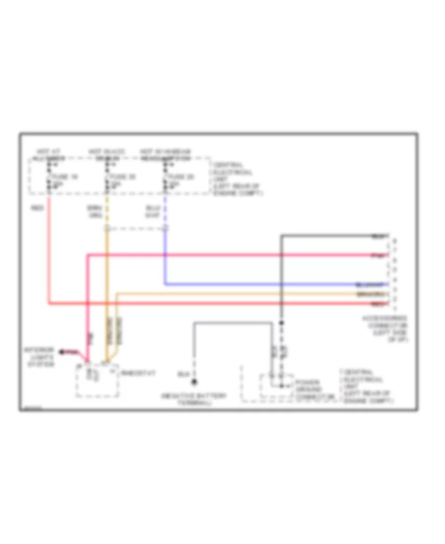
AIR CONDITIONING
2.3L
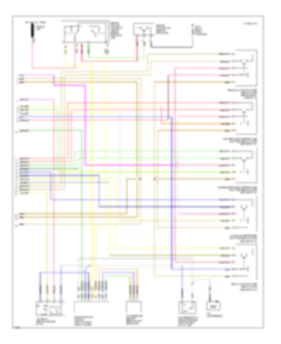
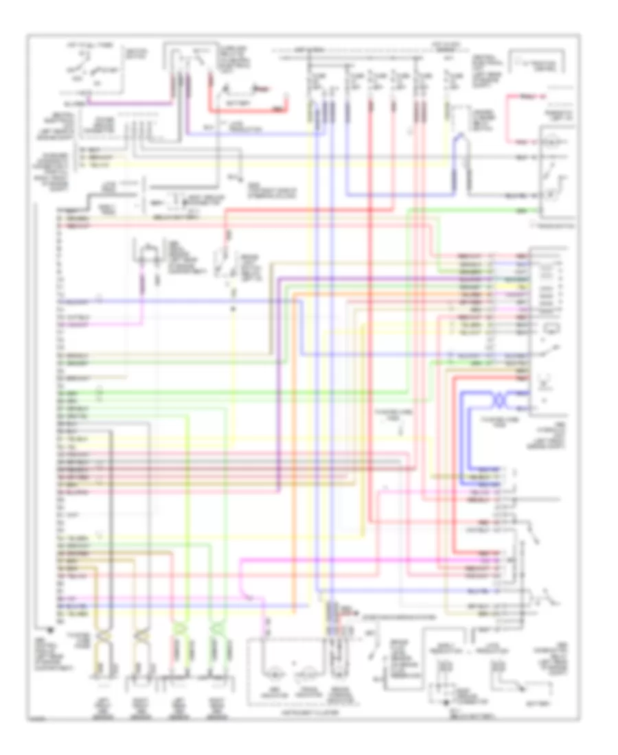
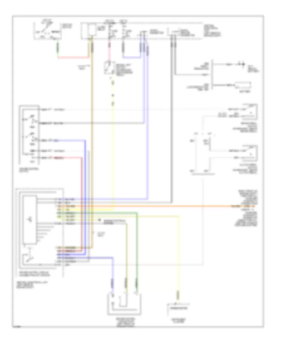
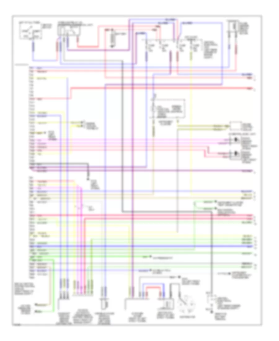
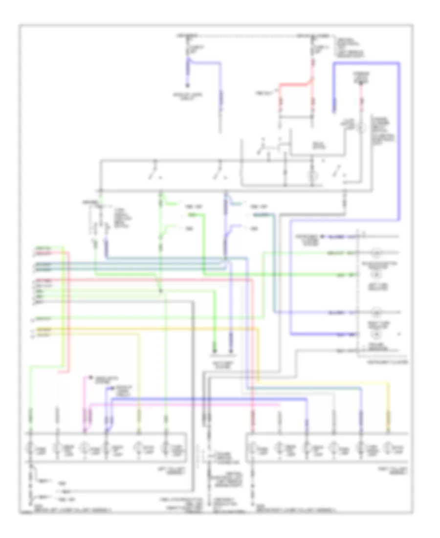
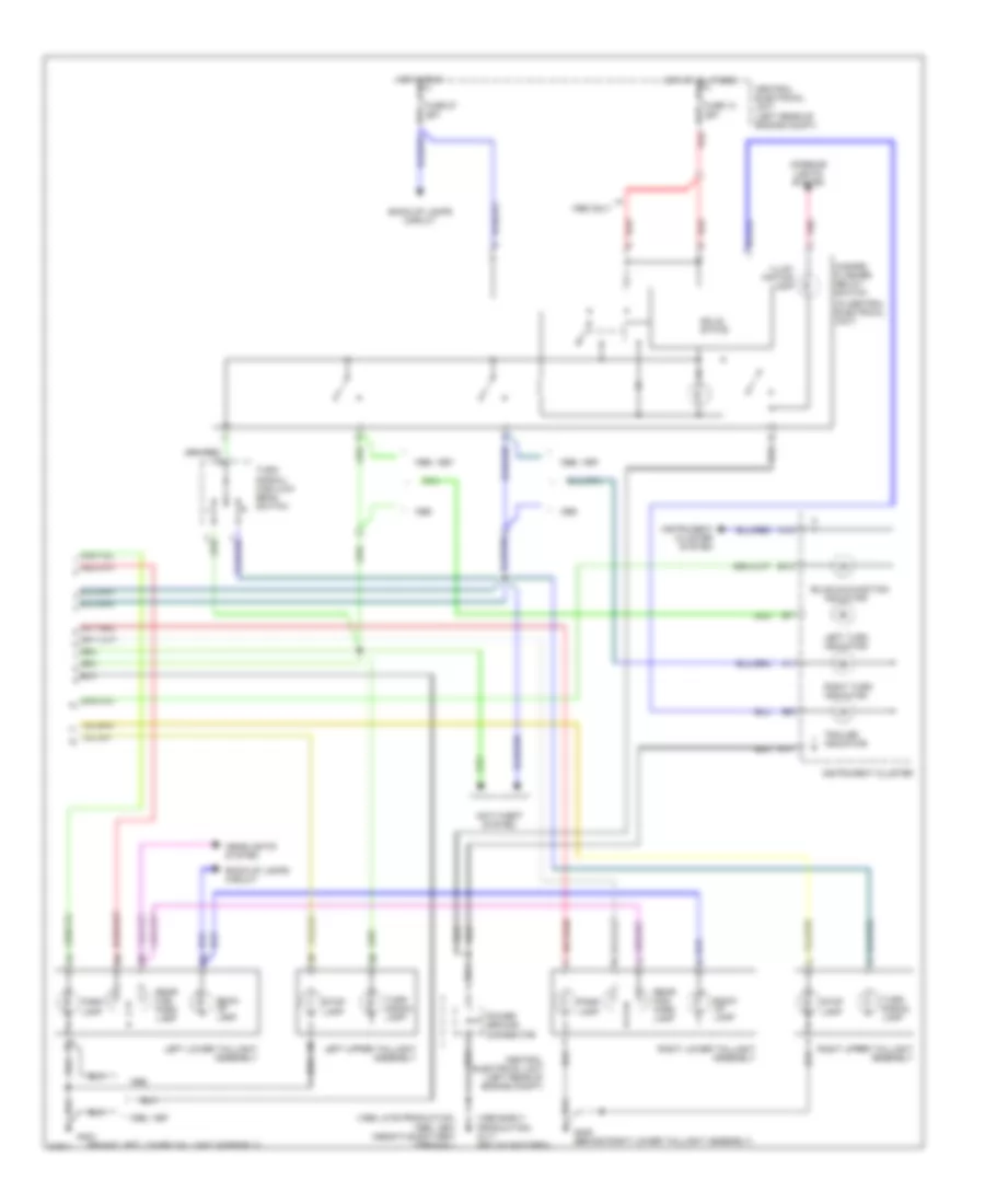
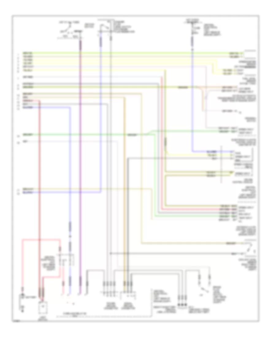
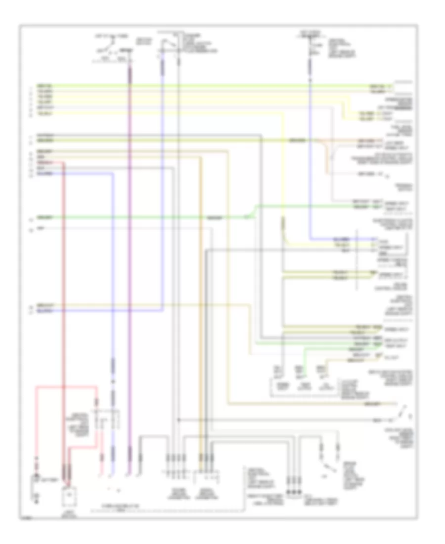
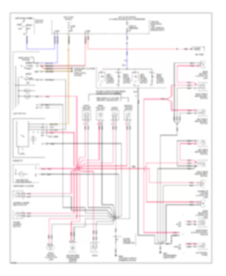
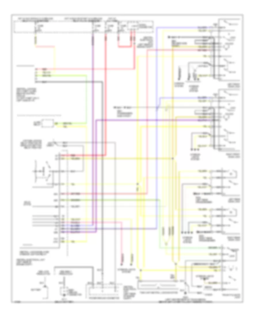
2.3L Turbo, Air Conditioning Wiring Diagrams (1 of 2) for Volvo 850 1995
 https://portal-diagnostov.com/license.html
Automotive Electricians Portal FZCO
Automotive Electricians Portal FZCO
https://portal-diagnostov.com/license.html
https://portal-diagnostov.com/license.html
Automotive Electricians Portal FZCO
Automotive Electricians Portal FZCO
List of elements for 2.3L Turbo, Air Conditioning Wiring Diagrams (1 of 2) for Volvo 850 1995:
- (1995)
- (1995) (1996)
- (1996)
- (headliner, above passenger's seat)
- A10
- A11
- A12
- A13
- A14
- A15
- A16
- A17
- A18
- A19
- A20
- A21
- A22
- A23
- A24
- A25
- A26
- A27
- A28
- A29
- A30
- Ambient temperature sensor (right rear of engine compartment)
- Anti-theft system
- B10
- B11
- B12
- B13
- B14
- B15
- B16
- C 1995 vftc
- C10
- Cabin temperature sensor, driver's side (headliner, above driver's seat)
- Cabin temperature sensor, passenger's side
- Diagnostic socket b (right front of engine compartment) data link connector
- Ecc control module (center of i/p)
- Fuse 11-31 25a
- Fuse 11-5 30a
- Fuse block
- G203 ("a" post, passenger's side)
- Generator
- Heater fan motor
- Heater fan power module (behind right side of i/p)
- Hot at all times
- Hot in on
- Instrument cluster
- Interior lights system
- Left duct temperature sensor (center of i/p)
- Pnk
- Red
- Right duct temperature sensor (center of i/p)
- Solar sensor/anti-theft indicator
- Temp sensor
- Vehicle speed
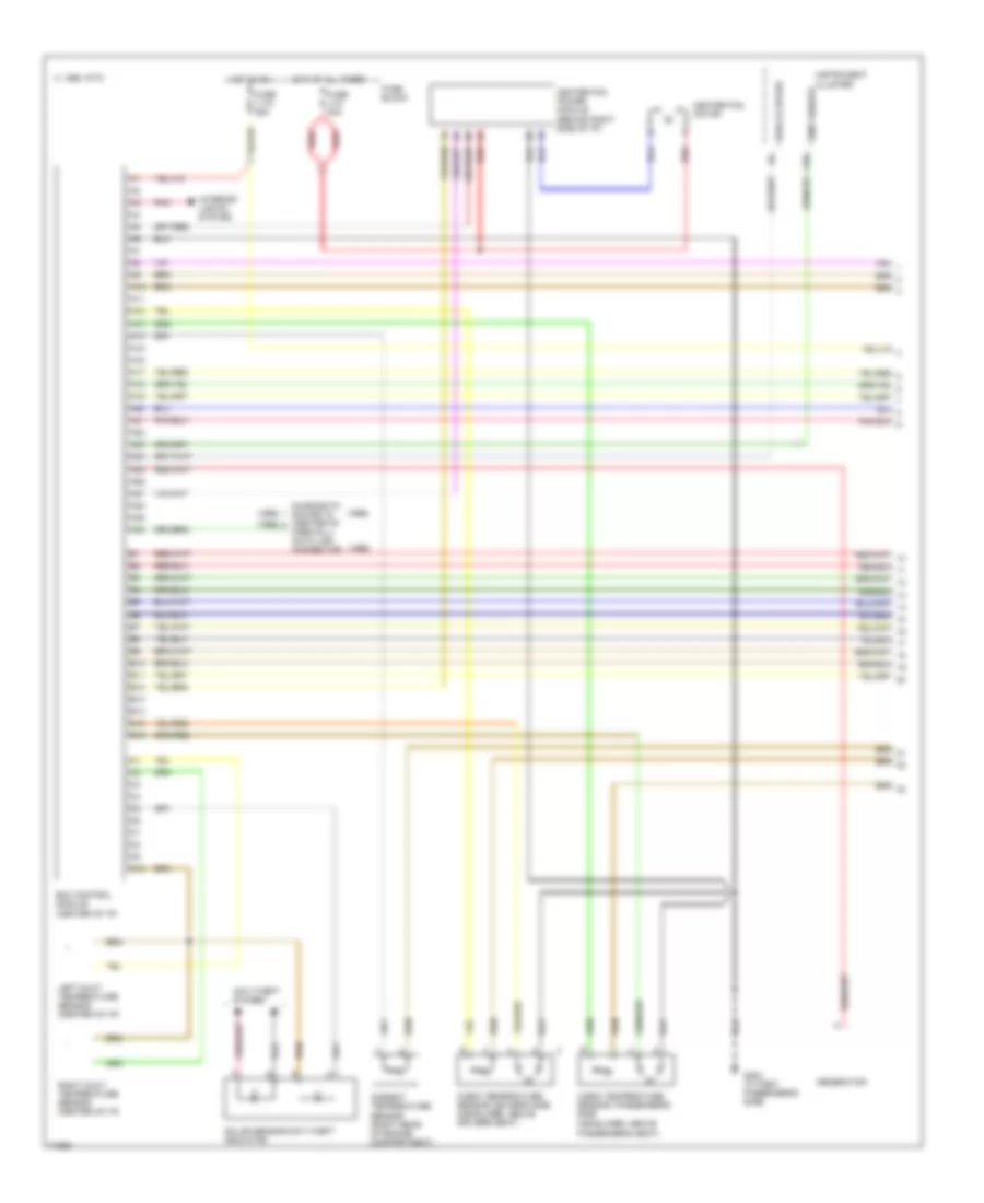
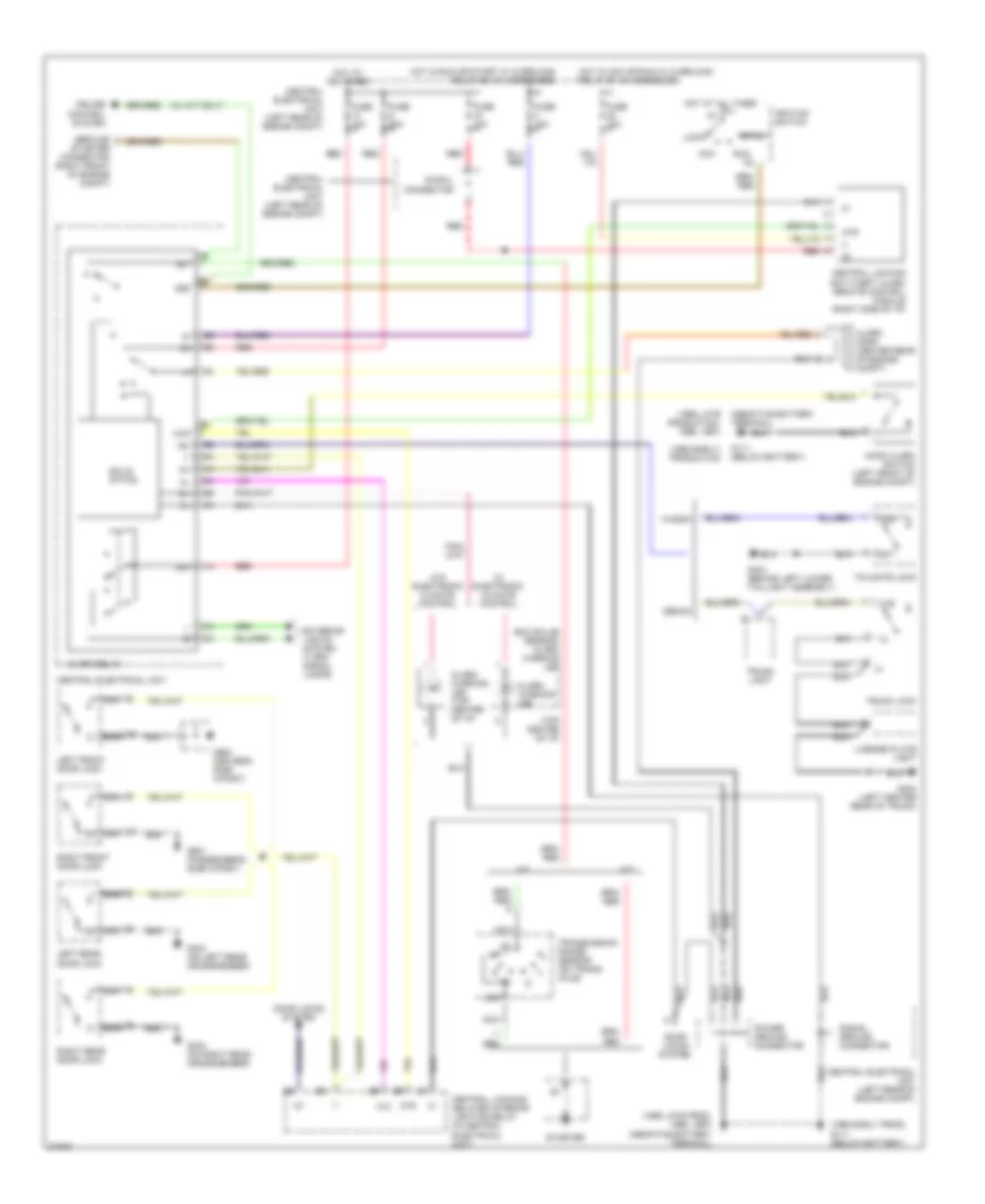
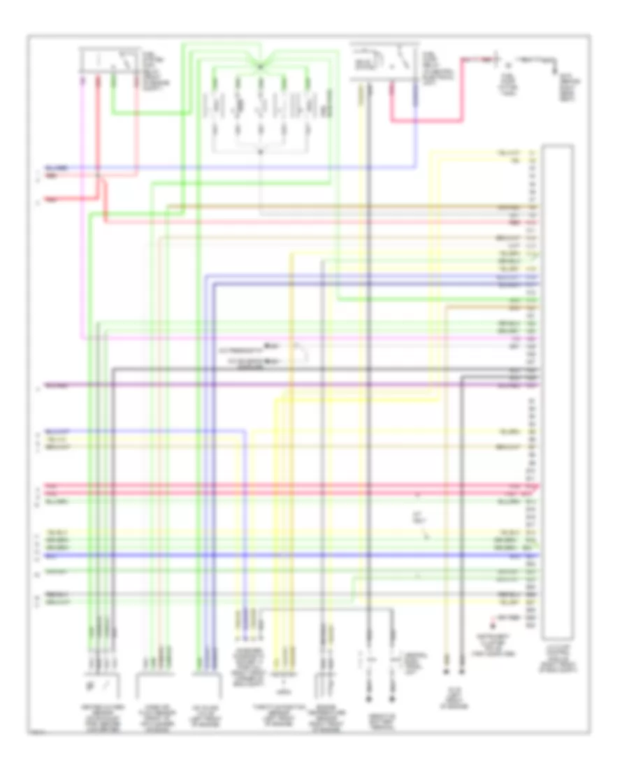
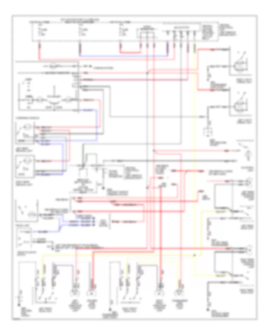
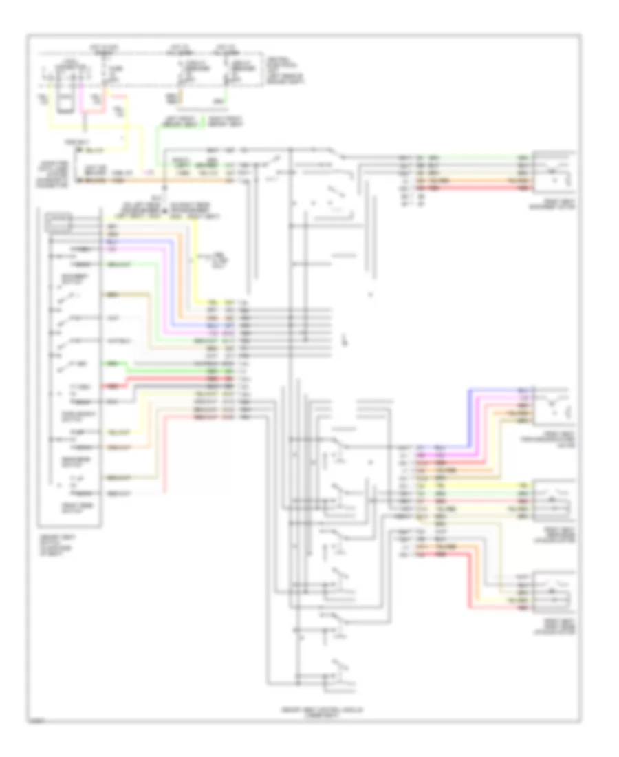
2.3L Turbo, Air Conditioning Wiring Diagrams (2 of 2) for Volvo 850 1995
 https://portal-diagnostov.com/license.html
Automotive Electricians Portal FZCO
Automotive Electricians Portal FZCO
https://portal-diagnostov.com/license.html
https://portal-diagnostov.com/license.html
Automotive Electricians Portal FZCO
Automotive Electricians Portal FZCOList of elements for 2.3L Turbo, Air Conditioning Wiring Diagrams (2 of 2) for Volvo 850 1995:
- (center of i/p)
- A/c compressor
- A/c pressostat (rear of engine compartment on a/c line)
- A/c pressure sensor (behind right headlamp)
- A/c relay (behind center of i/p)
- A22
- B23
- B25
- B28
- B29
- B40
- C 1995 vftc
- Driver's side temperature shutter servo motor (center of i/p)
- Engine control module (next to right shock tower)
- Engine cooling fan (behind radiator)
- Engine cooling fan relay (above engine radiator fan)
- Floor and defroster shutter servo motor
- Fusible link
- G119 (right front of engine)
- Hot at all times
- Passenger's side temperature shutter servo motor (center of i/p)
- Recirculation shutter servo motor (behind right side of i/p)
- Red
- Ventilation shutter servo motor
2.4L
2.4L, Air Conditioning Wiring Diagrams, Auto A/C (1 of 2) for Volvo 850 1995
 https://portal-diagnostov.com/license.html
Automotive Electricians Portal FZCO
Automotive Electricians Portal FZCO
https://portal-diagnostov.com/license.html
https://portal-diagnostov.com/license.html
Automotive Electricians Portal FZCO
Automotive Electricians Portal FZCOList of elements for 2.4L, Air Conditioning Wiring Diagrams, Auto A/C (1 of 2) for Volvo 850 1995:
- (1995)
- (1996)
- (headliner, above passenger's seat)
- A10
- A11
- A12
- A13
- A14
- A15
- A16
- A17
- A18
- A19
- A20
- A21
- A22
- A23
- A24
- A25
- A26
- A27
- A28
- A29
- A30
- Ambient temperature sensor (right rear of engine compartment)
- Anti-theft system
- B10
- B11
- B12
- B13
- B14
- B15
- B16
- C 1995 vftc
- C10
- Cabin temperature sensor, driver's side (headliner, above driver's seat)
- Cabin temperature sensor, passenger's side
- Diagnostic socket b (center of firewall) data link connector
- Ecc control module (center of i/p)
- Fuse 11-31 25a
- Fuse 11-5 30a
- Fuse block
- G203 ("a" post, passenger's side)
- Generator
- Heater fan motor
- Heater fan power module (behind right side of i/p)
- Hot at all times
- Hot in on
- Instrument cluster
- Interior lights system
- Left duct temperature sensor (center of i/p)
- Pnk
- Red
- Right duct temperature sensor (center of i/p)
- Solar sensor/anti-theft indicator
- Temp sensor
- Vehicle speed
2.4L, Air Conditioning Wiring Diagrams, Auto A/C (2 of 2) for Volvo 850 1995
 https://portal-diagnostov.com/license.html
Automotive Electricians Portal FZCO
Automotive Electricians Portal FZCO
https://portal-diagnostov.com/license.html
https://portal-diagnostov.com/license.html
Automotive Electricians Portal FZCO
Automotive Electricians Portal FZCOList of elements for 2.4L, Air Conditioning Wiring Diagrams, Auto A/C (2 of 2) for Volvo 850 1995:
- (center of i/p)
- A/c compressor
- A/c high pressure sensor (front of engine compartment, on high pressure line)
- A/c pressostat (rear of engine compartment on a/c line)
- A/c relay (behind center of i/p)
- A17
- A25
- A26
- B23
- B25
- B27
- B28
- Driver's side temperature shutter servo motor (center of i/p)
- Engine cooling fan (behind radiator)
- Engine cooling fan relay (above engine radiator fan)
- Ezk (di) ignition system control module (right side of engine compartment)
- Floor and defroster shutter servo motor
- Fusible link
- G119 (right front of engine)
- Hot at all times
- Lh 3.2mfi control module (right side of engine compartment)
- Passenger's side temperature shutter servo motor (center of i/p)
- Recirculation shutter servo motor (behind right side of i/p)
- Red
- Ventilation shutter servo motor
2.4L, Air Conditioning Wiring Diagrams, Manual A/C for Volvo 850 1995
 https://portal-diagnostov.com/license.html
Automotive Electricians Portal FZCO
Automotive Electricians Portal FZCO
https://portal-diagnostov.com/license.html
https://portal-diagnostov.com/license.html
Automotive Electricians Portal FZCO
Automotive Electricians Portal FZCOList of elements for 2.4L, Air Conditioning Wiring Diagrams, Manual A/C for Volvo 850 1995:
- (right side of engine compartment)
- A/c compressor
- A/c control panel
- A/c high pressure sensor (front of vehicle, on high pressure line)
- A/c pressostat (rear of engine compartment, on a/c line)
- A/c relay (center of i/p)
- A/c switch
- A17
- A25
- A26
- B25
- B27
- B28
- C 1995 vftc
- Engine cooling fan (behind radiator)
- Engine cooling fan relay (above engine radiator fan)
- Ezk (di) ignition system control module
- Fuse 11-31 25a
- Fuse 11-5 30a
- Fuse block
- Fusible link
- G119 (right front of engine)
- G201 (below right side of i/p)
- Heater fan
- Heater fan resistor (center of i/p)
- Hot at all times
- Hot in on
- Interior lights system
- Lh 3.2mfi control module (right side of engine compartment)
- Max fan relay
- Off
- Pnk
- Recirc switch
- Recirculation shutter servo motor (center of i/p)
- Red
- Solid state
ANTI-LOCK BRAKES
Anti-lock Brake Wiring Diagrams for Volvo 850 1995
 https://portal-diagnostov.com/license.html
Automotive Electricians Portal FZCO
Automotive Electricians Portal FZCO
https://portal-diagnostov.com/license.html
https://portal-diagnostov.com/license.html
Automotive Electricians Portal FZCO
Automotive Electricians Portal FZCOList of elements for Anti-lock Brake Wiring Diagrams for Volvo 850 1995:
- (below battery)
- (on brake fluid reservoir)
- A13
- A18
- A28
- A29
- Abs combination relay (left rear of engine compt)
- Abs control module (left rear of engine compartment)
- Abs hydraulic unit (left front engine compt)
- Abs indicator
- Abs pedal sensor (left rear of engine compartment)
- Acc
- Battery
- Body ground connector
- Brake fluid level sensor
- Brake light switch (below left i/p)
- Brake warning indicator
- Central electrical unit (left rear of engine compt)
- Control
- Early prod
- Early production
- Fuse 10a
- Fuse 15a
- Fuse 30a
- G111
- G111 (below battery)
- G205 (top right side of steering column)
- Hazard/ flasher relay switch
- Hot at all times
- Hot in acc or run
- Hot in run
- Ignition switch
- Instrument cluster
- Late prod
- Late production
- Left front abs sensor
- Left rear abs sensor
- Nca
- Off
- On-board diagnostic connector a (partial) (right front of engine compt)
- Overload relay #2 (in central electrical unit)
- Pnk
- Power ground connector
- Red
- Rheostat (left i/p)
- Right front abs sensor
- Right rear abs sensor
- Start
- Starting/charging system
- Tracs indicator
- Tracs switch
- Twisted wire pair
- Twisted wire pairs
- W/ traction
ANTI-THEFT
Base Anti-theft Wiring Diagram for Volvo 850 1995
 https://portal-diagnostov.com/license.html
Automotive Electricians Portal FZCO
Automotive Electricians Portal FZCO
https://portal-diagnostov.com/license.html
https://portal-diagnostov.com/license.html
Automotive Electricians Portal FZCO
Automotive Electricians Portal FZCOList of elements for Base Anti-theft Wiring Diagram for Volvo 850 1995:
- (1995 early prod) g111 (below battery)
- (1995 early) production
- (1995 late production, 1996, 1997)
- (top center of i/p)
- (w/ a/t only)
- 30-rail connector
- 30k
- 31b
- 50e
- 50f
- 50s
- A/t
- Acc
- Al2
- Alarm horn (center rear of engine compt)
- Alarm relay
- Alarm warning led
- Alarm warning led (top center of i/p)
- Atr
- Central electrical unit
- Central electrical unit (left rear of engine compt)
- Central locking anti-theft alarm remote control module (right side of i/p)
- Central locking/ delayed interior lighting relay (in central electrical unit)
- Cruise control system
- Door locks system
- Ecc solar sensor/ alarm warning led
- Exterior lights system (turn- signal lamps)
- Fuse 10a
- Fuse 15a
- Fuse 25a
- G111 (below battery)
- G303 (on right rear crossmember)
- G304 (on left rear crossmember)
- G404 (behind left lower taillight assembly)
- G404 (left center rear of trunk)
- G900 (driver's side a-post)
- G901 (passenger's side a-post)
- Hood alarm switch (left front of engine compt)
- Hot at all times
- Hot in acc or run w/ overload relay #1 (x+) energized
- Hot in run or start w/ overload relay #2 (15+) energized
- Ignition switch
- Left front door lock
- Left rear door lock
- License plate light
- Lock
- M/t
- Nca
- Nca t
- Power ground connector
- Red
- Right front door lock
- Right rear door lock
- Run
- Sedan
- Service starter connector (right front of engine compt)
- Signal ground connector
- Solid state
- Start
- Starter
- Tailgate lock
- Transmission range sensor (on trans- axle)
- Trunk light
- Trunk lock
- W/ electronic climate control
- W/o electronic climate control
- Wagon
COMPUTER DATA LINES
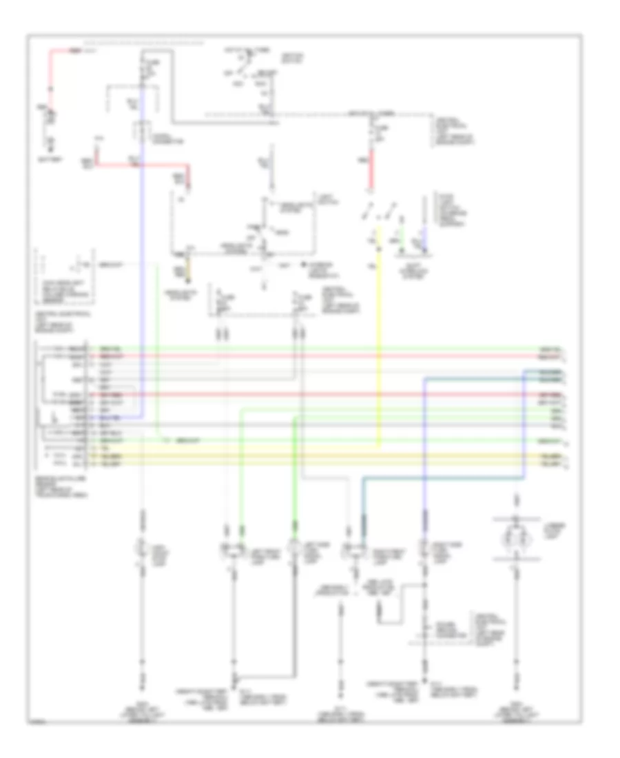
Computer Data Lines for Volvo 850 1995
 https://portal-diagnostov.com/license.html
Automotive Electricians Portal FZCO
Automotive Electricians Portal FZCO
https://portal-diagnostov.com/license.html
https://portal-diagnostov.com/license.html
Automotive Electricians Portal FZCO
Automotive Electricians Portal FZCOList of elements for Computer Data Lines for Volvo 850 1995:
- 30-rail connector
- A30
- Abs control module (next to left shock tower)
- Aw50-42 automatic transmission control module (right side of engine compt)
- B22
- B36
- Body ground connector
- Central electrical unit (left rear of engine comp)
- Cruise control module (in central electrical unit)
- Electronic climate control module (center of i/p)
- Fuse 10a
- Fuse 15a
- G111 (below battery)
- G125 (next to starter)
- G901 (passenger's side a-post)
- Hot at all times
- Hot in acc or run
- Instrument cluster (vdo type only)
- Left seat control module (under left front seat)
- Motronic 4.3 mfi control module (right side of engine compt)
- On-board diagnostic connector a (right front of engine compt)
- On-board diagnostic connector b (right front of engine compt)
- On-board diagnostic ii connector (16-pin) (center console, forward gear shifter)
- Power ground connector
- Red
- Right seat control module (under right front seat)
- Srs sensor module (below center console)
COOLING FAN
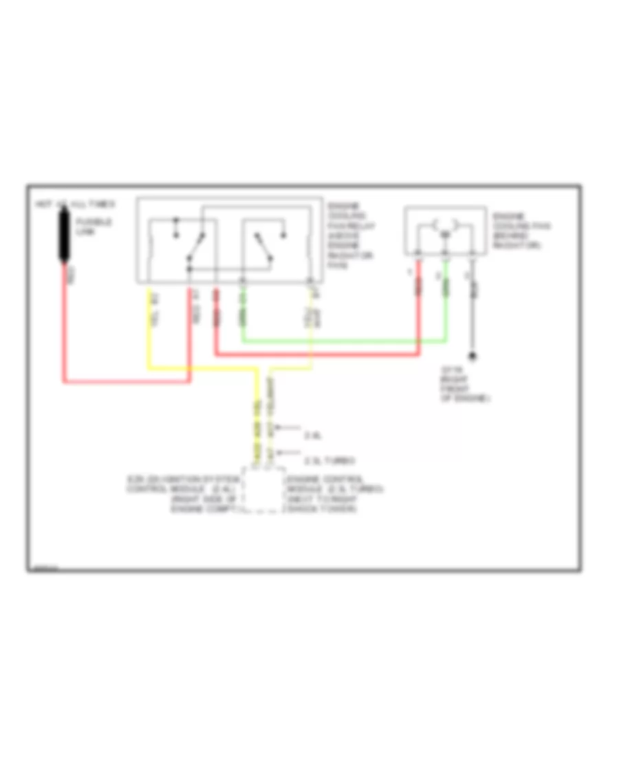
Cooling Fan Wiring Diagram for Volvo 850 1995
 https://portal-diagnostov.com/license.html
Automotive Electricians Portal FZCO
Automotive Electricians Portal FZCO
https://portal-diagnostov.com/license.html
https://portal-diagnostov.com/license.html
Automotive Electricians Portal FZCO
Automotive Electricians Portal FZCOList of elements for Cooling Fan Wiring Diagram for Volvo 850 1995:
- (2.3l turbo)
- (2.4l) control module
- (right side of engine compt)
- 2.3l turbo
- 2.4l
- A17
- A22
- A26
- Engine control module (next to right shock tower)
- Engine cooling fan (behind radiator)
- Engine cooling fan relay (above engine radiator fan)
- Ezk (di) ignition system
- Fusible link
- G119 (right front of engine)
- Hot at all times
- Red
CRUISE CONTROL
Cruise Control Wiring Diagram for Volvo 850 1995
 https://portal-diagnostov.com/license.html
Automotive Electricians Portal FZCO
Automotive Electricians Portal FZCO
https://portal-diagnostov.com/license.html
https://portal-diagnostov.com/license.html
Automotive Electricians Portal FZCO
Automotive Electricians Portal FZCOList of elements for Cruise Control Wiring Diagram for Volvo 850 1995:
- (-)
- (1995)
- (1996-97)
- (right front of engine compt) (1995 partial) on-board diagnostic connector b
- (w/ a/t) (w/ m/t)
- 15i-rail connector
- A/t
- Acc
- Alarm relay
- Battery
- Brake light switch (on bracket, above brake pedal)
- Brake pedal switch (on bracket, above brake pedal)
- Central electrical unit (left rear of engine compt)
- Clutch pedal switch (on bracket, above clutch pedal)
- Cruise control module (unused pins not shown)
- Cruise control switch
- Cruise control vacuum pump (left front of engine compt)
- Dec
- Early production
- Engine controls system
- Fuse 10a
- G111 (below battery)
- Hot at all times
- Hot in run
- Ignition switch
- Instrument cluster
- Late production, 1996, 1997
- M/t
- Nca
- Off
- On-board diagnostic connector (1996-97 partial) (center console forward shifter)
- Red
- Res
- Signal ground connector
- Speedometer
- Start
- W/ a/t only
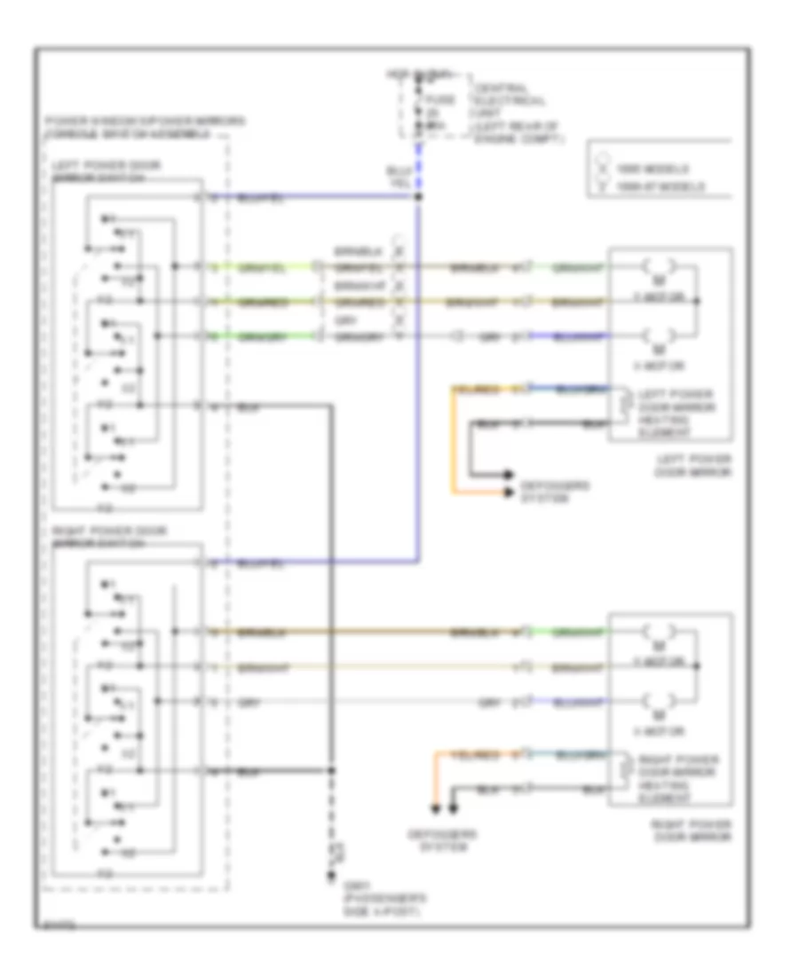
DEFOGGERS
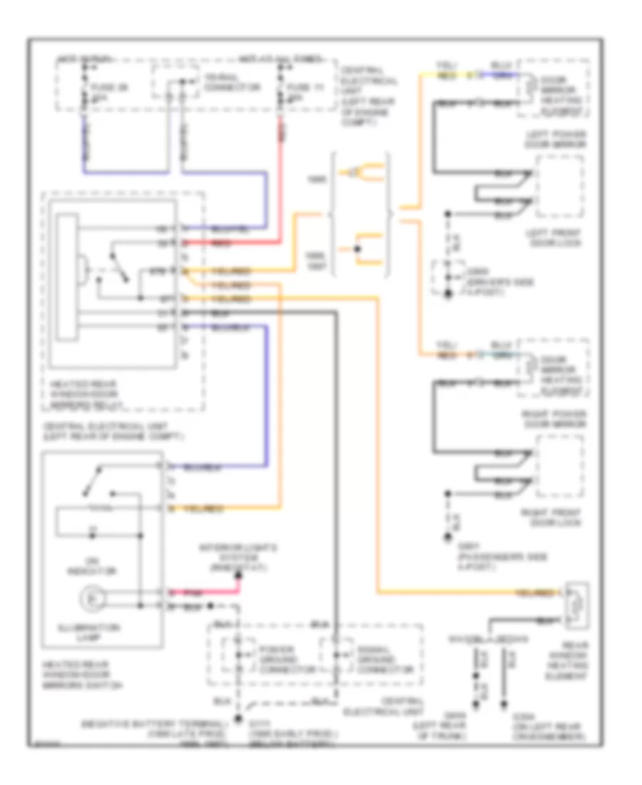
Defogger Wiring Diagram for Volvo 850 1995
 https://portal-diagnostov.com/license.html
Automotive Electricians Portal FZCO
Automotive Electricians Portal FZCO
https://portal-diagnostov.com/license.html
https://portal-diagnostov.com/license.html
Automotive Electricians Portal FZCO
Automotive Electricians Portal FZCOList of elements for Defogger Wiring Diagram for Volvo 850 1995:
- 15i
- 15i-rail connector
- 1996,
- 87b
- Central electrical unit
- Central electrical unit (left rear of engine compt)
- Ddor mirror heating element
- Door mirror heating element
- Fuse 11 30a
- Fuse 28 10a
- G111 (1995 early prod.) (below battery)
- G304 (on left rear crossmember)
- G900 (driver's side a-post)
- G901 (passenger's side a-post)
- Heated rear window/door mirrors relay
- Heated rear window/door mirrors switch
- Hot at all times
- Hot in run
- Illumination lamp
- Interior lights system (rheostat)
- Left front door lock
- Left power door mirror
- On indicator
- Pnk
- Power ground connector
- Rear window heating element
- Red
- Right front door lock
- Right power door mirror
- Sedan
- Signal ground connector
- Wagon
ENGINE PERFORMANCE
2.3L
2.3L Turbo, Engine Performance Wiring Diagrams (1 of 2) for Volvo 850 1995
 https://portal-diagnostov.com/license.html
Automotive Electricians Portal FZCO
Automotive Electricians Portal FZCO
https://portal-diagnostov.com/license.html
https://portal-diagnostov.com/license.html
Automotive Electricians Portal FZCO
Automotive Electricians Portal FZCOList of elements for 2.3L Turbo, Engine Performance Wiring Diagrams (1 of 2) for Volvo 850 1995:
- (a/t)
- (m/t)
- A/t
- A10
- A11
- A12
- A13
- A14
- A15
- A16
- A17
- A18
- A19
- A20
- A21
- A22
- A23
- A24
- A25
- A26
- A27
- A28
- A29
- A30
- A31
- A32
- A33
- A34
- A35
- A36
- A37
- A38
- A39
- A40
- A41
- A42
- Battery
- Camshaft position sensor (behind distributor)
- Central electrical unit (left rear corner of engine compt.)
- Egr converter (center front of eng compt)
- Egr temperature sensor (left front of eng compt, above stater motor)
- Engine cooling fan relay
- Engine temperature sensor (right front of eng)
- Evap valve (left front of eng compt)
- Fuel injectors
- Fuel system main relay (front of eng compt)
- Fuse #1 15a
- Fuse #15 10a
- Fuse #33 15a
- G119 (left front of eng)
- Heated oxygen sensor (front) (on exhaust pipe, before converter)
- Heated oxygen sensor (rear) (california) (on exhaust pipe, after converter)
- Hot in acc or run
- Iac idling valve (left front of eng)
- Knock sensor (front) (right front of eng)
- Knock sensor (rear) (left front of eng)
- M/t
- Mass air flow sensor (on air intake duct)
- Motronic 4.3 mfi control module (right front of engine compartment)
- Nca
- Pnk
- Ptc resistor (left side of eng)
- Red
- Throttle position sensor (left front of eng)
- Turbo control valve (left side 0f eng)
2.3L Turbo, Engine Performance Wiring Diagrams (2 of 2) for Volvo 850 1995
 https://portal-diagnostov.com/license.html
Automotive Electricians Portal FZCO
Automotive Electricians Portal FZCO
https://portal-diagnostov.com/license.html
https://portal-diagnostov.com/license.html
Automotive Electricians Portal FZCO
Automotive Electricians Portal FZCOList of elements for 2.3L Turbo, Engine Performance Wiring Diagrams (2 of 2) for Volvo 850 1995:
- (partial) (in console, front of gear selector)
- A/c pressostat (air conditioning system)
- A/c pressure sensor (cooling fans system)
- A/c relay (w/ ecc)
- A/c solenoid coupling
- A10
- A18
- Acc
- Accelerometer (center rear of eng compt)
- Aw 50-42 automatic transmission control module (left front of eng compt)
- B10
- B11
- B12
- B13
- B14
- B15
- B16
- B17
- B18
- B19
- B20
- B21
- B22
- B23
- B24
- B25
- B26
- B27
- B28
- B29
- B30
- B31
- B32
- B33
- B34
- B35
- B36
- B37
- B38
- B39
- B40
- B41
- B42
- Central electrical unit
- Central electrical unit (left rear corner of engine compt.)
- Cruise control module (in central elec. unit)
- Di power stage (front of left strut tower)
- Distributor
- Ecc control module pin a23 (optional)
- Fuel pump (in fuel tank)
- Fuel pump relay (in central electrical unit)
- Fuse #2 15a
- G102 left front shock tower)
- G119 (left front of engine)
- G202 (left side of i/p)
- G310 (behind right rear seat)
- Hot at all times
- Igniti0n coil (front of left strut tower)
- Ignition switch
- Instrument cluster
- Instrument cluster (temp. gauge) pin a26
- Instrument cluster pin a11 (tachometer)
- Instrument cluster pin a9 (trip computer)
- J/b (30 rail) (in electrical central unit)
- Mal- function indicator "check engine"
- Motronic 4.3 mfi control module (right front of engine compart- ment)
- Nca
- Off
- On-board diagnostic
- On-board diagnostic ii socket
- Overload relay 15+ (in central electrical unit)
- Pin 1
- Pin 2
- Pin 3
- Pnk
- Pulse sensor (below distributor)
- Red
- Run
- Socket a (partial) (right front corner of eng compt)
- Solid state
- Speedo- meter (output)
- Start
2.4L
2.4L, Engine Performance Wiring Diagrams (1 of 2) for Volvo 850 1995
 https://portal-diagnostov.com/license.html
Automotive Electricians Portal FZCO
Automotive Electricians Portal FZCO
https://portal-diagnostov.com/license.html
https://portal-diagnostov.com/license.html
Automotive Electricians Portal FZCO
Automotive Electricians Portal FZCOList of elements for 2.4L, Engine Performance Wiring Diagrams (1 of 2) for Volvo 850 1995:
- (in central elec. unit)
- A/c high pressure sensor (w/ ecc)
- A/c pressostat
- A/c relay pin 4 (w/ ecc)
- A/t only
- A10
- A11
- A12
- A13
- A14
- A15
- A16
- A17
- A18
- A19
- A20
- A21
- A22
- A23
- A24
- A25
- A26
- A27
- A28
- A29
- A30
- Acc
- Aw 50-42 automatic transmission control module (right front of engine compt.)
- B10
- B11
- B12
- B13
- B14
- B15
- B16
- B17
- B18
- B19
- B20
- B21
- B22
- B23
- B24
- B25
- B26
- B27
- B28
- B29
- B30
- Battery
- Camshaft position sensor (behind distributor)
- Central electrical unit (left rear corner of engine compt.)
- Cruise control module
- Di power stage (front of left strut tower)
- Distributor
- Ecc control module pin a23 (optional)
- Engine cooling fan relay
- Ezk (di) ignition system control module (right front of engine compt.)
- Fuse #1 15a
- Fuse #2 15a
- Fuse #33 15a
- Fuse #8 40a
- G102 (on left front shock tower)
- G119 (left front of eng)
- Hot at all times
- Hot in acc or run
- Igniti0n coil (front of left strut tower)
- Ignition switch
- Instrument cluster
- Instrument cluster pin a11 (tachometer)
- Instrument cluster temp. gauge pin a26
- Knock sensor (front) (right front of eng)
- Knock sensor (rear) (left front of eng)
- Mal- function indicator "check engine"
- Nca
- Off
- Overload relay 15+ (in central electrical unit)
- Pnk
- Pulse sensor (below distri- butor)
- Red
- Run
- Speedo- meter (output)
- Start
- Variable intake manifold solenoid (left side of engine)
2.4L, Engine Performance Wiring Diagrams (2 of 2) for Volvo 850 1995
 https://portal-diagnostov.com/license.html
Automotive Electricians Portal FZCO
Automotive Electricians Portal FZCO
https://portal-diagnostov.com/license.html
https://portal-diagnostov.com/license.html
Automotive Electricians Portal FZCO
Automotive Electricians Portal FZCOList of elements for 2.4L, Engine Performance Wiring Diagrams (2 of 2) for Volvo 850 1995:
- A/c pressostat
- A/c solenoid coupling
- A/t only
- A10
- A11
- A12
- A13
- A14
- A15
- A16
- A17
- A18
- A19
- A20
- A21
- A22
- A23
- A24
- A25
- A26
- A27
- A28
- A29
- A30
- B10
- B11
- B12
- B13
- B14
- B15
- B16
- B17
- B18
- B19
- B20
- B21
- B22
- B23
- B24
- B25
- B26
- B27
- B28
- B29
- B30
- Central elec- trical unit
- Engine temperature sensor (right front of engine)
- Fuel injectors
- Fuel pump (in fuel tank)
- Fuel pump relay (in central electrical unit)
- Fuel system main relay (front of engine compt.)
- G119 (left front of engine)
- G310 (behind right rear seat)
- Heated oxygen sensor (on exhaust pipe, before converter)
- Iac idling valve (left front of engine)
- Instrument cluster pin a9 (trip computer)
- Lh 3.2 mfi control module (right front of eng compt)
- Mass air flow sensor (front of air cleaner housing)
- On-board diagnostic socket a (partial) (right front corner of eng compt)
- Pnk
- Red
- Solid state
- Throttle position sensor (left front of engine)
EXTERIOR LIGHTS
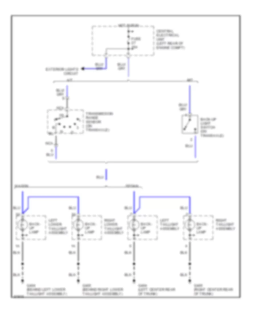
Back-up Lamps Wiring Diagram for Volvo 850 1995
 https://portal-diagnostov.com/license.html
Automotive Electricians Portal FZCO
Automotive Electricians Portal FZCO
https://portal-diagnostov.com/license.html
https://portal-diagnostov.com/license.html
Automotive Electricians Portal FZCO
Automotive Electricians Portal FZCOList of elements for Back-up Lamps Wiring Diagram for Volvo 850 1995:
- 15i
- A/t
- Back- up lamp
- Back-up light switch (on transaxle)
- Central electrical unit (left rear of engine compt)
- Exterior lights circuit
- Fuse 15a
- G404 (behind left lower taillight assembly)
- G404 (left center rear of trunk)
- G405 (behind right lower taillight assembly)
- G405 (right center rear of trunk)
- Hot in run
- Left lower taillight assembly
- Left taillight assembly
- M/t
- Nca
- Right lower taillight assembly
- Right taillight assembly
- Sedan
- Transmission range sensor (on transaxle)
- Wagon
Backup Lamps Wiring Diagram, Sedan & Wagon for Volvo 850 1995
 https://portal-diagnostov.com/license.html
Automotive Electricians Portal FZCO
Automotive Electricians Portal FZCO
https://portal-diagnostov.com/license.html
https://portal-diagnostov.com/license.html
Automotive Electricians Portal FZCO
Automotive Electricians Portal FZCOList of elements for Backup Lamps Wiring Diagram, Sedan & Wagon for Volvo 850 1995:
- 15i
- A/t
- Back- up lamp
- Back-up light switch (on transaxle)
- Central electrical unit (left rear of engine compt)
- Exterior lights circuit
- Fuse 15a
- G404 (behind left lower taillight assembly)
- G404 (left center rear of trunk)
- G405 (behind right lower taillight assembly)
- G405 (right center rear of trunk)
- Hot in run
- Left lower taillight assembly
- Left taillight assembly
- M/t
- Nca
- Right lower taillight assembly
- Right taillight assembly
- Sedan
- Transmission range sensor (on transaxle)
- Wagon
Exterior Lamps Wiring Diagram, Sedan (1 of 2) for Volvo 850 1995
 https://portal-diagnostov.com/license.html
Automotive Electricians Portal FZCO
Automotive Electricians Portal FZCO
https://portal-diagnostov.com/license.html
https://portal-diagnostov.com/license.html
Automotive Electricians Portal FZCO
Automotive Electricians Portal FZCOList of elements for Exterior Lamps Wiring Diagram, Sedan (1 of 2) for Volvo 850 1995:
- 15i
- 15i-rail connector
- 1995 early production
- 1995 late production, 1996, 1997
- 54h
- 54l
- 54r
- 56b
- 58a
- 58b
- 58c
- 58la
- 58lb
- 58ra
- 58rb
- Acc
- Battery
- Central electrical unit (left rear of engine compt)
- From trunk lock a (diagram 1 of 2)
- Fuse 10a
- G111 (1995 early prod) (below battery)
- G304 (left rear crossmember)
- G404 (left center rear of trunk)
- Head
- Headlights system
- High- mount stop lamp
- Hot at all times
- Ignition switch
- Interior lights (rheostat)
- Left front park/turn lamp
- Left side turn signal lamp
- License plate light
- License plate light (diagram 1 of 2)
- Light switch
- Main headlight relay/bulb failure warning sensor
- Nca
- Off
- Park
- Power ground connector
- Rear bulb failure warning sensor (left rear of trunk/cargo area)
- Red
- Right front park/turn lamp
- Right side turn signal lamp
- Run
- Shift interlock system
- Spoiler high- mount stop lamp
- Start
- Stop light switch (on brake pedal support)
- Trunk lock
- W/ rear spoiler
Exterior Lamps Wiring Diagram, Sedan (2 of 2) for Volvo 850 1995
 https://portal-diagnostov.com/license.html
Automotive Electricians Portal FZCO
Automotive Electricians Portal FZCO
https://portal-diagnostov.com/license.html
https://portal-diagnostov.com/license.html
Automotive Electricians Portal FZCO
Automotive Electricians Portal FZCOList of elements for Exterior Lamps Wiring Diagram, Sedan (2 of 2) for Volvo 850 1995:
- (1995 early production) g111 (below battery)
- (in central electrical unit)
- 1995 only
- 1996, 1997
- A17
- A18
- Anti-theft system
- B10
- Back- up lamp
- Back-up lamps circuit
- Bulb malfunction
- Central electrical unit (left rear of engine compt)
- Fuse 13 15a
- Fuse 27 15a
- G404 (behind left lower taillight assembly)
- G405 (behind right lower taillight assembly)
- Hazard flasher relay/ switch
- Headlights system
- Hot at all times
- Hot in run
- Illum- ination lamp
- Indicator
- Instrument cluster
- Instrument cluster system
- Interior lights system
- Left taillight assembly
- Left turn indicator
- Park lamp
- Pnk
- Power ground connector
- Rear fog lamp
- Red
- Right taillight assembly
- Right turn indicator
- Solid state
- Stop lamp
- Trailer indicator
- Turn signal lamp
- Turn signal/ high-low beam switch
Exterior Lamps Wiring Diagram, Wagon (1 of 2) for Volvo 850 1995
 https://portal-diagnostov.com/license.html
Automotive Electricians Portal FZCO
Automotive Electricians Portal FZCO
https://portal-diagnostov.com/license.html
https://portal-diagnostov.com/license.html
Automotive Electricians Portal FZCO
Automotive Electricians Portal FZCOList of elements for Exterior Lamps Wiring Diagram, Wagon (1 of 2) for Volvo 850 1995:
- 15i
- 15i-rail connector
- 1995 early production
- 1995 late production, 1996, 1997
- 54h
- 54l
- 54r
- 56b
- 58a
- 58b
- 58c
- 58la
- 58lb
- 58ra
- 58rb
- Acc
- Battery
- Central electrical unit (left rear of engine compt)
- Fuse 10a
- G111 (1995 early prod) (below battery)
- G404 (behind left lower taillight assembly)
- Head
- Headlights system
- High- mount stop lamp
- Hot at all times
- Ignition switch
- Interior lights (rheostat)
- Left front park/turn lamp
- Left side turn signal lamp
- License plate light
- Light switch
- Main headlight relay/bulb failure warning sensor
- Off
- Park
- Power ground connector
- Rear bulb failure sensor (left rear of trunk/cargo area)
- Red
- Right front park/turn lamp
- Right side turn signal lamp
- Run
- Shift interlock system
- Start
- Stop light switch (on brake pedal support)
Exterior Lamps Wiring Diagram, Wagon (2 of 2) for Volvo 850 1995
 https://portal-diagnostov.com/license.html
Automotive Electricians Portal FZCO
Automotive Electricians Portal FZCO
https://portal-diagnostov.com/license.html
https://portal-diagnostov.com/license.html
Automotive Electricians Portal FZCO
Automotive Electricians Portal FZCOList of elements for Exterior Lamps Wiring Diagram, Wagon (2 of 2) for Volvo 850 1995:
- (1995 early production) g111 (below battery)
- (behind left lower taillight assembly)
- (in central electrical unit)
- 1995 only
- 1996, 1997
- A17
- A18
- Anti-theft system
- B10
- Back- up lamp
- Back-up lamps circuit
- Bulb malfunction
- Central electrical unit (left rear of engine compt)
- Fuse 13 15a
- Fuse 27 15a
- G404
- G405 (behind right lower taillight assembly)
- Hazard flasher relay/ switch
- Headlights system
- Hot at all times
- Hot in run
- Illum- ination lamp
- Indicator
- Instrument cluster
- Instrument cluster system
- Interior lights system
- Left lower taillight assembly
- Left turn indicator
- Left upper taillight assembly
- Park lamp
- Pnk
- Power ground connector
- Rear fog/ park lamp
- Red
- Right lower taillight assembly
- Right turn indicator
- Right upper taillight assembly
- Solid state
- Stop lamp
- Trailer indicator
- Turn signal lamp
- Turn signal/ high-low beam switch
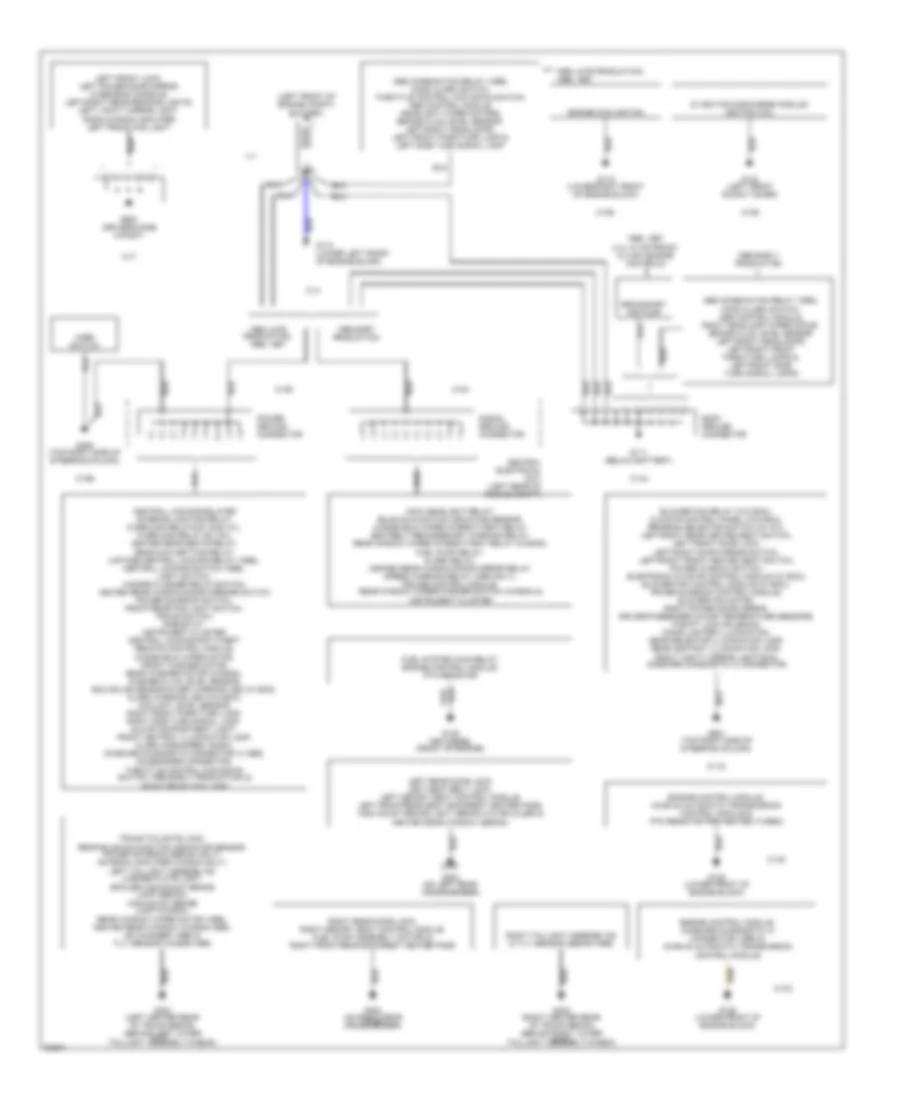
GROUND DISTRIBUTION
Ground Distribution Wiring Diagram for Volvo 850 1995
 https://portal-diagnostov.com/license.html
Automotive Electricians Portal FZCO
Automotive Electricians Portal FZCO
https://portal-diagnostov.com/license.html
https://portal-diagnostov.com/license.html
Automotive Electricians Portal FZCO
Automotive Electricians Portal FZCOList of elements for Ground Distribution Wiring Diagram for Volvo 850 1995:
- (left front of engine compt) battery
- 1/1-
- 1995 early production
- 1995 eary production
- 1995 late production, 1996, 1997
- 1996, 1997 2.4l w/ motronic (4.4 mfi) engine controls
- 31/15
- 31/32
- 31/33
- 31/4
- 31/44
- 31/47
- 31/50
- 31/51
- 31/52
- 31/55
- 31/65
- 31/7
- Abs combination relay (1995) hood alarm switch, throttle control kick down switch, abs control module headlight wiper motors, brake fluid level sensor, left/right headlamps, left front park/turn lamp & left side turn signal lamp
- Abs combination relay (1995), hood alarm switch, abs control module, right headlamp wiper motor, brake fluid level sensor left/right headlamps, left/right front park/turn lamps & left/right side turn signal lamps
- Blower fan relay (w/o ecc), climate control panel (w/o ecc), program selector switch (w/ a/t), left/right rear heated seat switch, left front door lock, left/right door mirror switch, left/right front heated seat switch, power window switch, electronic climate control module (w/ ecc), blower fan control module (w/ ecc), power sunroof control module, blower fan motor, right power door mirror, driver/passenger in-car temperature sensors, p-shift lock solenoid, cigar lighter illumination, gear selector illumination lamp, rear ashtray illumination lamp, right vanity mirror lighting & on-board diagnostic (ii) connector
- Body ground connector
- Central electrical unit (left rear of engine compt)
- Central locking/delayed interior lighting relay, overload relays #1 & #3 (x+), overload relay #2 (15+), heated rear seats relay, deadlock setting relay, 2-stage central locking relay (1996), central locking switch (1996), light switch, hazard flasher relay/switch, heated rear window/door mirrors switch power sunroof switch, front/rear fog light switch, tracs switch, rheostat, instrument cluster, central locking/anti-theft remote control module, windshield wiper motor, front washer motor, rear washer motor (wagon), washer fluid level sensor, ecc solar sensor/alarm warning led (w/ ecc), alarm warning led (w/o ecc), coolant level sensor, right front park/turn lamp, right side turn signal lamp, glove compartment light, front ashtray illumination lamp, alarm horn/siren, radio, on-board diagnostic connector a (1995), accesories connector, throttle control kick-down switch (1995 early production) & right front fog lamp
- Di ignition discharge module/ ignition coil
- Engine control module, aw50-42 automatic transmission control module & ptc resistor pre-heater (turbo)
- Engine control module, on-board diagnostic (ii) connector (1995) & aw50-42 automatic transmission control module
- Engine cooling fan
- Fuel system main relay, engine control module, ptc resistor
- G102 (left front shock tower)
- G110 (lower left front of engine block)
- G111 (below battery)
- G119 (lower right front of engine block)
- G125 (lower front of engine block)
- G125 1997 diesel (front of engine)
- G205 (top right side of steering column)
- G303 (on right rear 31/48 crossmember)
- G304 (on left rear crossmember)
- G403 (right center rear of trunk-sedan) (behind right lower 31/12 taillight assembly-wagon)
- G404 (left center rear of trunk-sedan) (behind left lower 31/11 taillight assembly-wagon)
- G900 (driver's side a-post)
- G901 (top right side of steering column)
- Horn switch
- Left front lock, left power door mirror, overhead console, left/right rear reading lights, left vanity mirror light, radio & radio amplifier left front fog light
- Left rear door lock, left seat belt lock, left memory seat control module, left front/rear seat backrest heater pads, high mount brake light (sedan w/o sploiler) & heated rear window (sedan)
- Main headlight relay/ bulb malfunction indicator sensor, windshield wiper intermittent relay, seatbelt reminder/key warning relay, rear window wiper intermittent relay (wagon), fuel pump relay, alarm relay, heated rear window/door mirror relay, speed warning relay (1995 only), cruise control module, rear window wiper/washer switch (wagon) & instrument cluster
- Power ground connector
- Right rear door lock, right memory seat control module, fuel pump assembly (motor) & right front/rear backrest heater pads
- Right taillight assembly(s) & tilt sensor (sedan-1996)
- Secondary air pump
- Signal ground connector
- Trunk/tailgate lock, rear bulb malfunction indicator sensor, power antenna (sedan only), antenna amplifier (wagon only), left taillight assembly(s) license plate light, spoiler high-mount brake lamp (sedan), high-mount brake lamp (wagon), rear window wiper motor (1996), heated rear window (wagon-1996), cd changer (1996) & tilt sensor (wagon-1996)
HEADLIGHTS
Headlamps/Fog Lamps Wiring Diagram (1 of 2) for Volvo 850 1995
 https://portal-diagnostov.com/license.html
Automotive Electricians Portal FZCO
Automotive Electricians Portal FZCO
https://portal-diagnostov.com/license.html
https://portal-diagnostov.com/license.html
Automotive Electricians Portal FZCO
Automotive Electricians Portal FZCOList of elements for Headlamps/Fog Lamps Wiring Diagram (1 of 2) for Volvo 850 1995:
- (1995 early production)
- (below battery)
- 15i
- 56a
- 56b
- 56b6l
- 56b6r
- 56bs
- 81a
- Acc
- Battery
- Canada
- Central electrical unit (left rear of engine compt)
- Central electrical unit (left side of engine compt)
- Exc usa/ canada
- Flash
- Fuse 15a
- G111
- Head
- High
- Hot at all times
- Ignition switch
- Illumination lamps
- Instrument cluster system
- Interior lights
- Left headlight
- Light switch
- Lock
- Main headlight relay/ bulb failure warning sensor
- Off
- Park
- Pnk
- Rear bulb failure warning sensor (left rear corner of trunk/cargo area)
- Red
- Right headlight
- Run
- Signal ground connector
- Solid state
- Start
- System (rheostat)
- Turn signal/ high-low beam switch
- Usa
Headlamps/Fog Lamps Wiring Diagram (2 of 2) for Volvo 850 1995
 https://portal-diagnostov.com/license.html
Automotive Electricians Portal FZCO
Automotive Electricians Portal FZCO
https://portal-diagnostov.com/license.html
https://portal-diagnostov.com/license.html
Automotive Electricians Portal FZCO
Automotive Electricians Portal FZCOList of elements for Headlamps/Fog Lamps Wiring Diagram (2 of 2) for Volvo 850 1995:
- (1995 early production) g111
- (below battery)
- (left center rear of trunk)
- A17
- A18
- B10
- Bulb failure warning indicator
- Central electrical unit (left rear of engine compt)
- Central electrical unit (left side of engine compt)
- Exterior lights system
- Fog light relay
- Front fog lights bridge
- Front fog lights switch
- Fuse
- Fuse 10a
- Fuse 15a
- G404
- G404 (behind left lower taillight assembly)
- G405 (behind right lower taillight assembly)
- G405 (right center rear of trunk)
- High beam indicator
- Hot at all times
- Illumination lamp
- Instrument cluster
- Instrument cluster system (overload relay #2 [15+])
- Interior lights system (rheostat)
- Left front fog lamp
- Left lower taillight assembly (wagon)
- Left taillight assembly (sedan)
- Off
- On indicator
- Pnk
- Power ground connector
- Rear bulb failure warning sensor (left rear of trunk)
- Rear fog lamp
- Rear fog lights switch
- Rear fog lights warning indicator
- Rear fog/park lamp
- Red
- Right front fog lamp
- Right lower taillight assembly (wagon)
- Right taillight assembly (sedan)
- Sedan
- Wagon
Headlight Wiring Diagram (1 of 2) for Volvo 850 1995
 https://portal-diagnostov.com/license.html
Automotive Electricians Portal FZCO
Automotive Electricians Portal FZCO
https://portal-diagnostov.com/license.html
https://portal-diagnostov.com/license.html
Automotive Electricians Portal FZCO
Automotive Electricians Portal FZCOList of elements for Headlight Wiring Diagram (1 of 2) for Volvo 850 1995:
- (1995 early production)
- (below battery)
- 15i
- 56a
- 56b
- 56b6l
- 56b6r
- 56bs
- 81a
- Acc
- Battery
- Canada
- Central electrical unit (left rear of engine compt)
- Central electrical unit (left side of engine compt)
- Exc usa/ canada
- Flash
- Fuse 15a
- G111
- Head
- High
- Hot at all times
- Ignition switch
- Illumination lamps
- Instrument cluster system
- Interior lights
- Left headlight
- Light switch
- Lock
- Main headlight relay/ bulb failure warning sensor
- Off
- Park
- Pnk
- Rear bulb failure warning sensor (left rear corner of trunk/cargo area)
- Red
- Right headlight
- Run
- Signal ground connector
- Solid state
- Start
- System (rheostat)
- Turn signal/ high-low beam switch
- Usa
Headlight Wiring Diagram (2 of 2) for Volvo 850 1995
 https://portal-diagnostov.com/license.html
Automotive Electricians Portal FZCO
Automotive Electricians Portal FZCO
https://portal-diagnostov.com/license.html
https://portal-diagnostov.com/license.html
Automotive Electricians Portal FZCO
Automotive Electricians Portal FZCOList of elements for Headlight Wiring Diagram (2 of 2) for Volvo 850 1995:
- (1995 early production) g111
- (below battery)
- (left center rear of trunk)
- A17
- A18
- B10
- Bulb failure warning indicator
- Central electrical unit (left rear of engine compt)
- Central electrical unit (left side of engine compt)
- Exterior lights system
- Fog light relay
- Front fog lights bridge
- Front fog lights switch
- Fuse
- Fuse 10a
- Fuse 15a
- G404
- G404 (behind left lower taillight assembly)
- G405 (behind right lower taillight assembly)
- G405 (right center rear of trunk)
- High beam indicator
- Hot at all times
- Illumination lamp
- Instrument cluster
- Instrument cluster system (overload relay #2 [15+])
- Interior lights system (rheostat)
- Left front fog lamp
- Left lower taillight assembly (wagon)
- Left taillight assembly (sedan)
- Off
- On indicator
- Pnk
- Power ground connector
- Rear bulb failure warning sensor (left rear of trunk)
- Rear fog lamp
- Rear fog lights switch
- Rear fog lights warning indicator
- Rear fog/park lamp
- Red
- Right front fog lamp
- Right lower taillight assembly (wagon)
- Right taillight assembly (sedan)
- Sedan
- Wagon
HORN
Horn Wiring Diagram for Volvo 850 1995
 https://portal-diagnostov.com/license.html
Automotive Electricians Portal FZCO
Automotive Electricians Portal FZCO
https://portal-diagnostov.com/license.html
https://portal-diagnostov.com/license.html
Automotive Electricians Portal FZCO
Automotive Electricians Portal FZCOList of elements for Horn Wiring Diagram for Volvo 850 1995:
- 1995 early production
- 1995 late production & 1996-97
- Central electrical unit (left rear of engine compt)
- Fuse 34 25a
- G205 (top right side of steering column)
- Horn 1
- Horn 2
- Horn switch
- Hot in acc or run
- Slip ring (in steering column)
INSTRUMENT CLUSTER
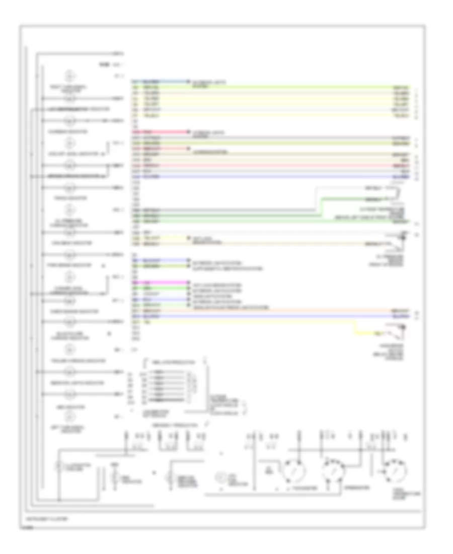
Instrument Cluster Wiring Diagram, VDO (1 of 2) for Volvo 850 1995
 https://portal-diagnostov.com/license.html
Automotive Electricians Portal FZCO
Automotive Electricians Portal FZCO
https://portal-diagnostov.com/license.html
https://portal-diagnostov.com/license.html
Automotive Electricians Portal FZCO
Automotive Electricians Portal FZCOList of elements for Instrument Cluster Wiring Diagram, VDO (1 of 2) for Volvo 850 1995:
- (unused pins not shown)
- 1. avg speed 2. instant fuel consumption 3. avg fuel consumption 4. outside temp 5. distance since last reset 6. distance to empty 7. diagnosis
- 1995 early production
- 1995 late production
- 5v reg
- 8v reg
- A10
- A11
- A12
- A13
- A14
- A15
- A16
- A17
- A18
- A19
- A20
- A21
- A22
- A23
- A24
- A25
- A26
- A27
- A28
- A29
- A30
- Abs indicator
- Anti-lock brake system
- B10
- B11
- B12
- B13
- B14
- B15
- B16
- Brake warning indicator
- Bulb failure warning indicator
- Charging indicator
- Charging system
- Check engine indicator
- Computer datalines system
- Coolant level indicator
- D10
- D11
- Exterior lights system
- Fuel gauge
- Fuel indicator
- Fuse
- Hand brake switch (below center console)
- Headlights & exterior lights system
- Headlights system
- High beam indicator
- Illumination (4 bulbs)
- Indicator
- Instrument cluster
- Interior lights system
- Kedt
- Kefa
- Left turn signal
- Low
- Low gear selection indicator
- Microprocessor
- N/a
- Nca
- Oil pressure
- Oil pressure sensor (front of engine)
- Outside temperature sensor (behind left side of front bumper)
- Park brake indicator
- Pnk
- Rear fog lights indicator
- Reset
- Right turn signal
- Service reminder indicator
- Speedo- meter
- Srs
- Srs indicator
- Tacho- meter
- Temperature gauge
- Tracs indicator
- Trailer warning indicator
- Trip computer controls
- Trip computer or ambient temperature/ clock module 0r clock module
- Warning indicator
- Washer level
Instrument Cluster Wiring Diagram, VDO (2 of 2) for Volvo 850 1995
 https://portal-diagnostov.com/license.html
Automotive Electricians Portal FZCO
Automotive Electricians Portal FZCO
https://portal-diagnostov.com/license.html
https://portal-diagnostov.com/license.html
Automotive Electricians Portal FZCO
Automotive Electricians Portal FZCOList of elements for Instrument Cluster Wiring Diagram, VDO (2 of 2) for Volvo 850 1995:
- A23
- A24
- Acc
- Aw 50-42 automatic transmisssion control module (right side of engine compt)
- B18
- B21
- B23
- B39
- Battery
- Brake fluid level switch (left rear of engine compt)
- Central electrical unit (left rear of engine compt)
- Coolant level sensor (right front of engine compt)
- Cruise control module
- Data
- Electronic climate control module (center of i/p)
- Fuel level sensor (in fuel tank)
- Fuse 10a
- G111 (1995 early prod) (below battery)
- Gnd
- Hot at all times
- Hot in run or start
- Ignition switch
- Light switch
- Low gear
- Mil
- Motronic 4.3 mfi control module (left side of engine compt)
- Off
- Overload relay #2 (15+)
- Power ground connector
- Program switch
- Pwr
- Red
- Rpm input
- Run
- Signal ground connector
- Speed input
- Speed warning relay
- Speedometer sensor (on transmission)
- Start
- Temp input
- Washer fluid level switch (in washer fluid reservoir)
Instrument Cluster Wiring Diagram, Yasaki (1 of 2) for Volvo 850 1995
 https://portal-diagnostov.com/license.html
Automotive Electricians Portal FZCO
Automotive Electricians Portal FZCO
https://portal-diagnostov.com/license.html
https://portal-diagnostov.com/license.html
Automotive Electricians Portal FZCO
Automotive Electricians Portal FZCOList of elements for Instrument Cluster Wiring Diagram, Yasaki (1 of 2) for Volvo 850 1995:
- (unused pins not shown)
- 1995 early production
- 1995 late production
- 5v reg
- A10
- A11
- A12
- A13
- A14
- A15
- A16
- A17
- A18
- A19
- A20
- A21
- A22
- A23
- A24
- A25
- A26
- A27
- A28
- A29
- A30
- Abs indicator
- Anti-lock brake system
- B10
- B11
- B12
- B13
- B14
- B15
- B16
- Brake warning indicator
- Bulb failure
- Charging indicator
- Charging system
- Check engine indicator
- Coolant level indicator
- D10
- Exterior lights system
- Fuel indicator
- Fuse
- Hand brake switch (below center console)
- Headlights & exterior lights system
- Headlights system
- High beam indicator
- Illumination (5 bulbs)
- Indicator
- Instrument cluster
- Interior lights system
- Left turn signal
- Low
- Low gear selection indicator
- Nca
- Oil pressure
- Oil pressure sensor (front of engine)
- Outside temperature sensor (behind left side of front bumper)
- Outside temperature/ clock module 0r clock module
- Park brake indicator
- Pnk
- Rear fog lights indicator
- Right turn signal
- Service reminder indicator
- Speedmeter
- Srs
- Srs indicator
- Tachometer
- Tank/ temperature gauge
- Tracs indicator
- Trailer warning indicator
- Warning indicator
- Washer level
Instrument Cluster Wiring Diagram, Yasaki (2 of 2) for Volvo 850 1995
 https://portal-diagnostov.com/license.html
Automotive Electricians Portal FZCO
Automotive Electricians Portal FZCO
https://portal-diagnostov.com/license.html
https://portal-diagnostov.com/license.html
Automotive Electricians Portal FZCO
Automotive Electricians Portal FZCOList of elements for Instrument Cluster Wiring Diagram, Yasaki (2 of 2) for Volvo 850 1995:
- A23
- A24
- Acc
- Aw 50-42 automatic transmisssion control module (right side of engine compt)
- B18
- B23
- B29
- Battery
- Brake fluid level switch (left rear of engine compt)
- Central electrical unit (left rear of engine compt)
- Coolant level sensor (right front of engine compt)
- Cruise control module
- Electronic climate control module (center of i/p)
- Ezk di ignition system control module (right side of engine compt)
- Fuel level sensor (in fuel tank)
- Fuse 10a
- G111 (1995 early prod) (below battery)
- Gnd
- Hot at all times
- Hot in run or start
- Ignition switch
- Lh 3.2 mfi control module (right rear of engine compt)
- Light switch
- Low gear
- Mil out
- Mil output
- Off
- Overload relay #2 (15+)
- Power ground connector
- Program switch
- Pwr
- Red
- Rpm output
- Run
- Signal ground connector
- Speed input
- Speed warning relay
- Speedometer sensor (on transmission)
- Start
- Temp input
- Temp output
- Washer fluid level switch (in washer fluid reservoir)
INTERIOR LIGHTS
Courtesy Lamps Wiring Diagram for Volvo 850 1995
 https://portal-diagnostov.com/license.html
Automotive Electricians Portal FZCO
Automotive Electricians Portal FZCO
https://portal-diagnostov.com/license.html
https://portal-diagnostov.com/license.html
Automotive Electricians Portal FZCO
Automotive Electricians Portal FZCOList of elements for Courtesy Lamps Wiring Diagram for Volvo 850 1995:
- (1996 sedan)
- (1996 wagon)
- (2)
- (left center rear of trunk-sedan) (behind left lower taillight assembly)
- (passenger's side a-post)
- (sedan)
- (wagon)
- 1995 sedan & wagon 0r 1996 wagon
- 1995 sedan & wagon or 1996 wagon
- 1996 sedan
- 30-rail connector
- 30l
- 31b
- 31l
- Anti- theft system
- Bp-
- Central electrical unit (left rear of engine compt)
- Central locking/ delayed courtesy lighting relay
- Deadlock setting relay or 2-stage central locking relay
- Door
- Driver's side entry lamp
- Fuse 10a
- Fuse 25a
- G205 (top right side of steering column)
- G303 (on right rear crossmember)
- G304 (on left rear crossmember)
- G407
- G900 (driver's side a-post)
- G901
- G901 (passenger's side a-post)
- Glove box light
- Hot at all times
- Hot in on or start w/ overload relay #2 (15+) energized
- Left front door lock
- Left front open-door warning lamp
- Left rear door lock
- Left rear open-door warning lamp
- Left rear reading light
- Left vanity mirror light
- Nca
- Nca 31d
- Nca t
- Overhead console
- Passenger's side entry lamp
- Power ground connector
- Red
- Right front door lock
- Right front open-door warning lamp
- Right rear door lock
- Right rear open-door warning lamp
- Right rear reading light
- Right vanity mirror light
- Seatbelt indicator
- Sedan
- Solid state
- T/f
- Trunk lamp
- Trunk/tailgate switch
- Warning system
Instrument Illumination Wiring Diagram for Volvo 850 1995
 https://portal-diagnostov.com/license.html
Automotive Electricians Portal FZCO
Automotive Electricians Portal FZCO
https://portal-diagnostov.com/license.html
https://portal-diagnostov.com/license.html
Automotive Electricians Portal FZCO
Automotive Electricians Portal FZCOList of elements for Instrument Illumination Wiring Diagram for Volvo 850 1995:
- (4 bulbs-vdo) (5 bulbs-yasaki)
- (not used)
- 10a
- 11a
- 15i
- 1996 models w/ 2-stage central locking only
- 56b
- A/c control panel
- A10
- A17
- Acc
- Battery
- Central electrical unit (left rear of engine compt)
- Central locking switch
- Cigarette lighter illumination lamp
- Circuit breaker
- Electronic climate control module
- Front ashtray illumination lamp
- Front fog light switch
- Fuse 5a
- G205 (top right side of steering column)
- G901 (passenger's side a-post)
- Gear selector illumination lamp
- Hazard flasher relay/switch
- Head
- Headlights system
- Heated rear window/door mirrors switch
- Hot at all times
- Hot in acc or run
- Hot in acc or run w/ overload relay #3 (x+) energized
- Ignition switch
- Instrument cluster
- Instrument cluster system
- Left front heated seat switch
- Left front power window switch
- Left rear heated seat switch
- Left rear power window switch
- Light switch
- Off
- Park
- Pnk
- Power ground connector
- Power sunroof switch
- Power window/power mirror console switch assembly
- Radio
- Rear ashtray illumination lamp
- Rear fog light switch
- Red
- Rheostat
- Right front heated seat switch
- Right front power window switch
- Right rear heated seat switch
- Right rear power window switch
- Run
- Start
- Tracs switch
- W/ auto a/c
- W/ manual a/c
MEMORY SYSTEMS
Memory Seats Wiring Diagram for Volvo 850 1995
 https://portal-diagnostov.com/license.html
Automotive Electricians Portal FZCO
Automotive Electricians Portal FZCO
https://portal-diagnostov.com/license.html
https://portal-diagnostov.com/license.html
Automotive Electricians Portal FZCO
Automotive Electricians Portal FZCOList of elements for Memory Seats Wiring Diagram for Volvo 850 1995:
- & 1997 only
- (1995)
- (1996, 97)
- (left seat)
- (on left rear crossmember) g304
- (on right rear crossmember) g303
- (right seat)
- (right) (left)
- 1995 only
- Back
- Backrest switch
- C10
- C11
- C12
- C13
- C14
- Central electrical unit (left rear of engine compt)
- Circuit breaker 30a
- Computer data lines system (diagnostic connector)
- D10
- D11
- D12
- D13
- D14
- D15
- D16
- Down
- Forw
- Forw-backw switch
- Front edge switch
- Front seat backrest motor
- Front seat forward-backward motor
- Front seat front edge up-down motor
- Front seat rear edge up-down motor
- Fuse 15a
- Hot at all times
- Hot in acc or run
- Left front memory seat
- M1+
- M1-
- M2+
- M2-
- M3+
- M3-
- M4+
- M4-
- Mem
- Memory seat control module (under seat)
- Memory seat switch (along side of seat)
- Nca
- R1+
- R1-
- R2+
- R2-
- R3+
- R3-
- R31
- R4+
- R4-
- Rear edge switch
- Red
- Right front memory seat
- Vg1
- Vg2
- Vg3/4
- Vr1
- Vr2
- Vr3
- Vr4
- X-rail connector
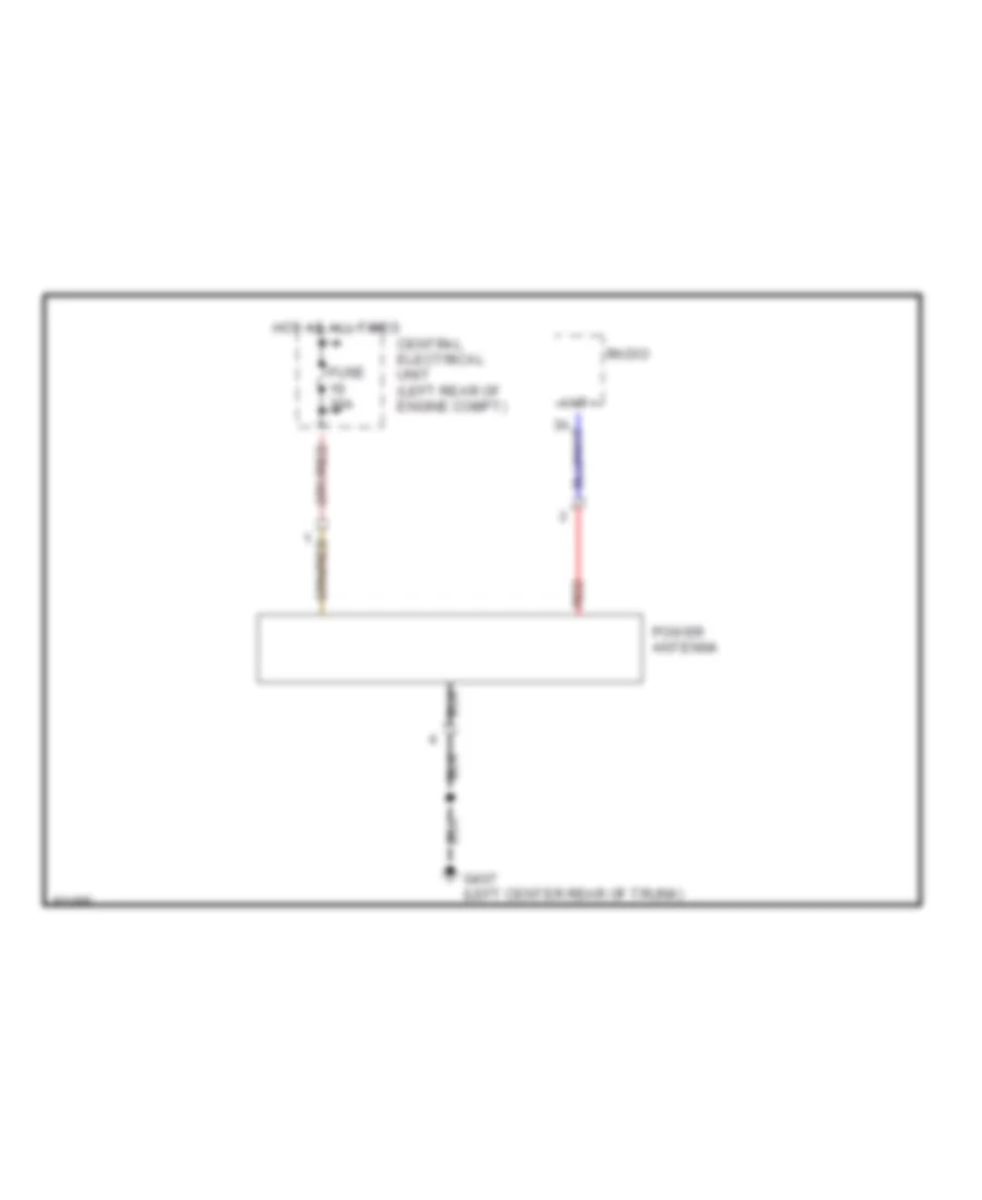
POWER ANTENNA
Power Antenna Wiring Diagram for Volvo 850 1995
 https://portal-diagnostov.com/license.html
Automotive Electricians Portal FZCO
Automotive Electricians Portal FZCO
https://portal-diagnostov.com/license.html
https://portal-diagnostov.com/license.html
Automotive Electricians Portal FZCO
Automotive Electricians Portal FZCOList of elements for Power Antenna Wiring Diagram for Volvo 850 1995:
- Ant+
- Central electrical unit (left rear of engine compt)
- Fuse 30a
- G407 (left center rear of trunk)
- Hot at all times
- Power antenna
- Radio
- Red
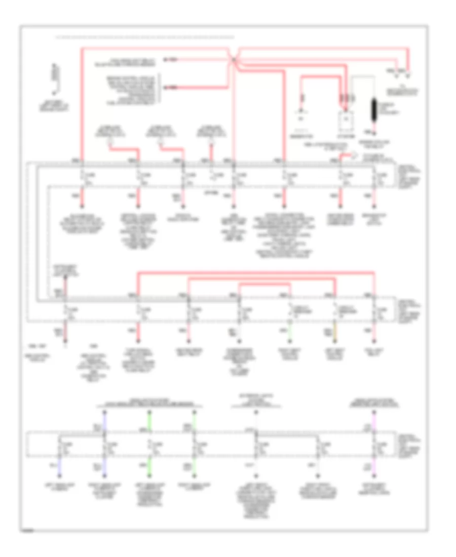
POWER DISTRIBUTION
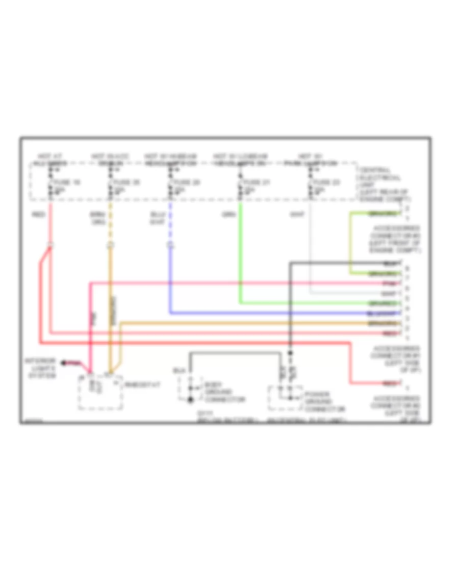
Accessories Connector Wiring Diagram, Early Production for Volvo 850 1995
 https://portal-diagnostov.com/license.html
Automotive Electricians Portal FZCO
Automotive Electricians Portal FZCO
https://portal-diagnostov.com/license.html
https://portal-diagnostov.com/license.html
Automotive Electricians Portal FZCO
Automotive Electricians Portal FZCOList of elements for Accessories Connector Wiring Diagram, Early Production for Volvo 850 1995:
- (in central elec unit)
- Accessories connector #1 (left side of i/p)
- Accessories connector #2 (left side of i/p)
- Accessories connector #3 (left front of engine compt)
- Body ground connector
- Central electrical unit (left rear of engine compt)
- Dim out
- Fuse 16 30a
- Fuse 20 15a
- Fuse 21 15a
- Fuse 23 10a
- Fuse 35 10a
- G111 (below battery)
- Hot at all times
- Hot in acc or run
- Hot w/ hi-beam headlamps on
- Hot w/ lo-beam headlamps on
- Hot w/ park lamps on
- Interior lights system
- Pnk
- Power ground connector
- Red
- Rheostat
Accessories Connector Wiring Diagram, Late Production for Volvo 850 1995
 https://portal-diagnostov.com/license.html
Automotive Electricians Portal FZCO
Automotive Electricians Portal FZCO
https://portal-diagnostov.com/license.html
https://portal-diagnostov.com/license.html
Automotive Electricians Portal FZCO
Automotive Electricians Portal FZCOList of elements for Accessories Connector Wiring Diagram, Late Production for Volvo 850 1995:
- Accessories connector (left side of i/p)
- Central electrical unit (left rear of engine compt)
- Dim out
- Fuse 16 30a
- Fuse 20 15a
- Fuse 35 10a
- Hot at all times
- Hot in acc or run
- Hot w/ hi-beam headlamps on
- Interior lights system
- Pnk
- Power ground connector
- Red
- Rheostat
Power Distribution Wiring Diagram (1 of 2) for Volvo 850 1995
 https://portal-diagnostov.com/license.html
Automotive Electricians Portal FZCO
Automotive Electricians Portal FZCO
https://portal-diagnostov.com/license.html
https://portal-diagnostov.com/license.html
Automotive Electricians Portal FZCO
Automotive Electricians Portal FZCOList of elements for Power Distribution Wiring Diagram (1 of 2) for Volvo 850 1995:
- (30-rail connector) obd (ii) diagnostic connector, driver's side entry lamp, passengers's side entry lamp, glove box light, door open warning lamps, trunk light, vanity mirror lights, ceiling light, central locking/anti-theft remote control module
- (spare)
- 1996 late production & 1997 only
- 1996, 1997
- Abs combination relay (1995) or abs control module (1996, 1997)
- Abs control module
- Abs control module (w/ traction control only) & abs combination relay
- Accessories connector & power antenna (sedan) or not used (wagon)
- Battery (left front of engine compt)
- Blower fan relay (w/o ecc) or blower fan (w/ ecc) & blower fan power module (w/ ecc)
- Brake/stop light switch
- Central electrical unit (left rear of engine compt)
- Central locking/ delayed interior lighting relay, alarm relay deadlock setting relay & 2-stage central locking relay (1996, 1997)
- Circuit breaker
- Engine control module, ezk (di) ignition system control module (1995), aw 50-42 automatic transmission control module & fuel system main relay
- Engine cooling fan relay
- Exterior lights system (light switch)
- Fog light relay
- Fuse
- Fuse 10a
- Fuse 15a
- Fuse 25a
- Fuse 30a
- Generator
- Headlights system (main headlight relay/bulb failure sensor)
- Headlights system (rear fog light switch)
- Heated rear seat relay
- Heated rear window/door mirror relay
- Instrument cluster & light switch
- Instrument cluster & rear fog lamps
- Left front park/turn lamp, license plate light, rear bulb failure warning sensor & accessories connector- (1995 early production)
- Left headlamp (hi-beam)
- Left headlamp (lo-beam) & accessories connector- (1995 early production)
- Left seat control module
- Main headlight relay/ bulb failure warning sensor
- Overload relay #1 (x+) (diagram 2 of 2)
- Overload relay #2 (15+) (diagram 2 of 2)
- Overload relay #3 (x+) (diagram 2 of 2)
- Radio & radio amplifier
- Red
- Right front park/turn lamp & rear bulb failure warning sensor
- Right headlamp (hi-beam) & instrument cluster
- Right headlamp (lo-beam)
- Right seat control module
- Starter
- To fuse 36 (diagram 2 of 2)
- To ignition switch (diagram 2 of 2)
- Turn signal/ high-low beam switch, hazard flasher relay/switch & alarm relay
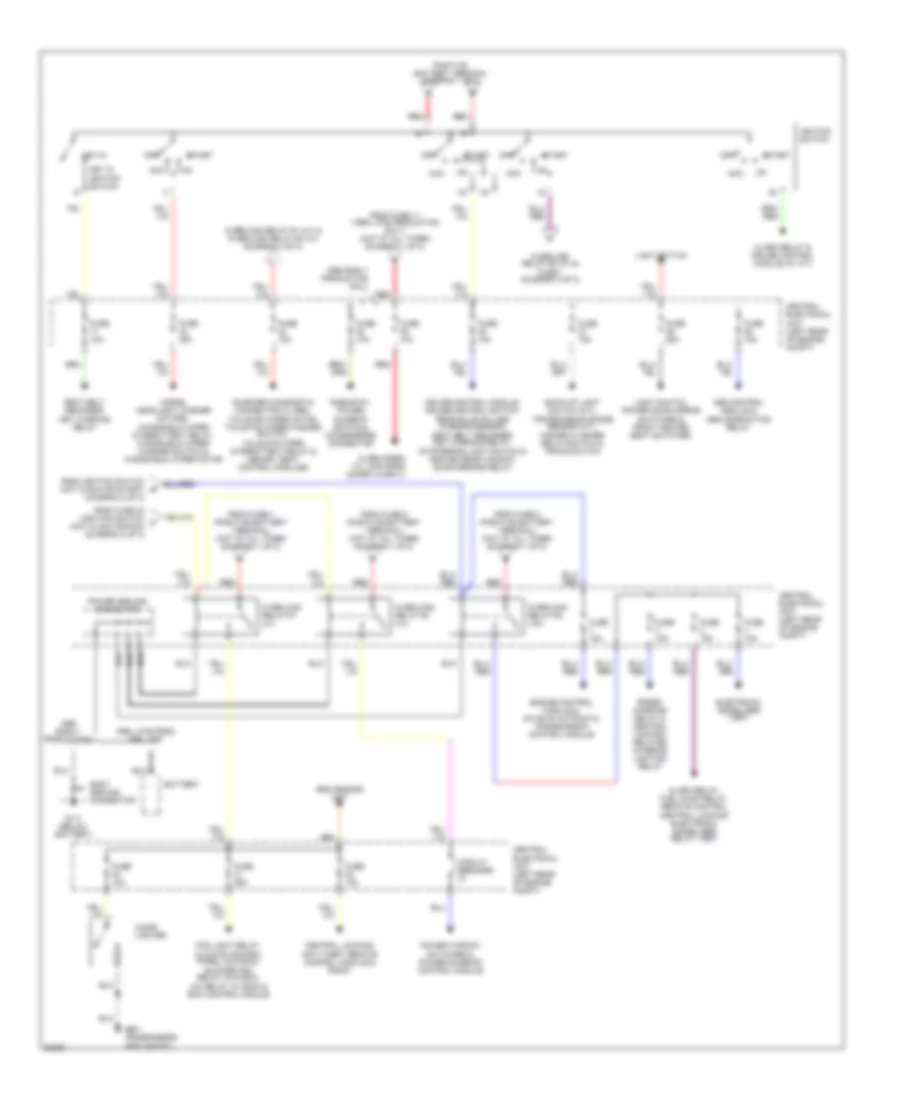
Power Distribution Wiring Diagram (2 of 2) for Volvo 850 1995
 https://portal-diagnostov.com/license.html
Automotive Electricians Portal FZCO
Automotive Electricians Portal FZCO
https://portal-diagnostov.com/license.html
https://portal-diagnostov.com/license.html
Automotive Electricians Portal FZCO
Automotive Electricians Portal FZCOList of elements for Power Distribution Wiring Diagram (2 of 2) for Volvo 850 1995:
- 15i
- 1995 late prod, 1996, 1997
- 1996 early production only
- Abs control module & abs combination relay
- Acc
- Alarm relay & cruise control module (w/ a/t)
- Alarm relay, fuel pump relay, remote control central locking/ electronic immobilizer relay (1997)
- Alarm siren (w/ late prod guard alarm ii)
- Back-up light switch (m/t), transmission range sensor (a/t), hazard flasher relay/switch & tracs switch
- Battery
- Body ground connector
- Central electrical unit (left rear of engine compt)
- Central locking/ anti-theft remote control module & radio
- Cigar lighter
- Circuit breaker
- Cruise control module, cruise control switch, rear bulb failure warning sensor, seat belt reminder/ key warning relay, stop/brake light switch & heated rear window/ door mirrors relay
- Early production
- Electronic immobilizer (1997)
- Engine control module & aw 50-42 automatic transmission control module
- Fog light relay, climate control panel (w/o ecc), blower fan relay (w/o ecc), a/c relay (w/ ecc) & ecc control module
- From fuse 11 (1996 late production only) (hot at all times) (diagram 1 of 2)
- From fuse 33 (ignition switch f (hot in acc or run) (diagram 2 of 2)
- From fuse 6 (positive battery terminal) (hot at all times) (diagram 1 of 2)
- From fuse 7 (positive battery terminal) (hot at all times) (diagram 1 of 2)
- From fuse 8 (positive battery terminal) (hot at all times) (diagram 1 of 2)
- From ignition switch (hot in run or start) (diagram 2 of 2)
- Fuse 10a
- Fuse 15a
- Fuse 25a
- G111 (below battery)
- G901 (passenger's side a-post)
- Horns, headlight washer motors, windshield wiper intermittent relay, windshield wiper/ washer switch & windshield wiper motor
- Ignition switch
- Key in ignition switch
- Key-in
- Light switch
- Light switch, power door mirror switches & front heated seat switches
- Off
- On-board diagnostic connector a (1995), tailgate wiper motor, tailgate wiper/washer switch, tailgate wiper intermittent relay & memory seat control modules
- Overload relay #1 (x+)
- Overload relay #1 (x+) & overload relay #3 (x+) (diagram 2 of 2)
- Overload relay #2 (15+)
- Overload relay #2 (x+) & fuse 1 (diagram 2 of 2)
- Overload relay #3 (x+)
- Positive battery terminal (diagram 1 of 1)
- Power ground connector
- Power window switches & power sunroof control module
- Red
- Rheostat, power sunroof switch & accessories connector
- Seat belt reminder/ key warning relay
- Speed warning relay & central locking/ delayed interior lighting relay
- Srs sensor unit
- Start
POWER DOOR LOCKS
Central Locking Wiring Diagram, with Deadlock for Volvo 850 1995
 https://portal-diagnostov.com/license.html
Automotive Electricians Portal FZCO
Automotive Electricians Portal FZCO
https://portal-diagnostov.com/license.html
https://portal-diagnostov.com/license.html
Automotive Electricians Portal FZCO
Automotive Electricians Portal FZCOList of elements for Central Locking Wiring Diagram, with Deadlock for Volvo 850 1995:
- (sedan only)
- 1995 early production
- 1995 late production
- 30-rail connector
- 31b
- 31d
- 85a
- 85b
- 85r
- Al1
- Al2
- Alarm relay
- Atr
- Battery
- Body ground connector
- Central electrical unit (left rear of engine compt)
- Central locking/ anti-theft alarm remote control module (w/ anti-theft only) (left side of i/p)
- Central locking/delayed interior lighting relay
- Deadlock setting relay
- Fuse 10a
- Fuse 25a
- G111 (below battery)
- G303 (right rear crossmember)
- G304 (left rear crossmember)
- G404 (left center rear of trunk-sedan) (behind left lower taillight assembly-wagon)
- G900 (driver's side a-post)
- G901 (passenger's side a-post)
- Hot at all times
- Hot in acc or run w/ overload relay #1 (x+) energized
- Hot in run or start w/ overload
- Interior lights system
- Left front door lock
- Left rear door lock
- Lock
- Mbh
- Mbl
- Mbls
- Nca
- Nca m+
- Nca mbls
- Nca t
- Power ground connector
- Red
- Relay #2 (15+) energized
- Right front door lock
- Right rear door lock
- Sedan
- Solid state
- Tank cap central locking motor
- Trunk/tailgate lock
- Unlock
- Wagon
- Warning system
Central Locking Wiring Diagram, without Deadlock for Volvo 850 1995
 https://portal-diagnostov.com/license.html
Automotive Electricians Portal FZCO
Automotive Electricians Portal FZCO
https://portal-diagnostov.com/license.html
https://portal-diagnostov.com/license.html
Automotive Electricians Portal FZCO
Automotive Electricians Portal FZCOList of elements for Central Locking Wiring Diagram, without Deadlock for Volvo 850 1995:
- (not used)
- (sedan only)
- 1995 early production
- 1995 late production
- 2-stage locking relay position or deadlock setting relay position
- 30-rail connector
- 31b
- 31d
- 85a
- 85b
- 85r
- Al1
- Al2
- Alarm relay
- Atr
- Battery
- Body ground connector
- Central electrical unit (left rear of engine compt)
- Central locking/ anti-theft alarm remote control module (w/ anti-theft only) (left side of i/p)
- Central locking/delayed interior lighting relay
- Fuse 10a
- Fuse 25a
- G111 (below battery)
- G303 (right rear crossmember)
- G304 (left rear crossmember)
- G404 (left center rear of trunk-sedan) (behind left lower taillight assembly-wagon)
- G900 (driver's side a-post)
- G901 (passenger's side a-post)
- Hot at all times
- Hot in acc or run w/ overload relay #1 (x+) energized
- Hot in run or start w/ overload
- Interior lights system
- Left front door lock
- Left rear door lock
- Lock
- Nca
- Nca t
- Power ground connector
- Red
- Relay #2 (15+) energized
- Right front door lock
- Right rear door lock
- Sedan
- Solid state
- Tank cap central locking motor
- Trunk/tailgate lock
- Unlock
- Wagon
- Warning system
POWER MIRRORS
Power Mirror Wiring Diagram for Volvo 850 1995
 https://portal-diagnostov.com/license.html
Automotive Electricians Portal FZCO
Automotive Electricians Portal FZCO
https://portal-diagnostov.com/license.html
https://portal-diagnostov.com/license.html
Automotive Electricians Portal FZCO
Automotive Electricians Portal FZCOList of elements for Power Mirror Wiring Diagram for Volvo 850 1995:
- 1995 models
- 1996-97 models
- Central electrical unit (left rear of engine compt)
- Defoggers system
- Fuse 25a
- G901 (passenger's side a-post)
- Hot in run
- Left power door mirror
- Left power door mirror heating element
- Left power door mirror switch
- Power windows/power mirrors console switch assembly
- Right power door mirror
- Right power door mirror heating element
- Right power door mirror switch
- X-motor
- Y-motor
POWER SEATS
Front Seat Heater Wiring Diagram for Volvo 850 1995
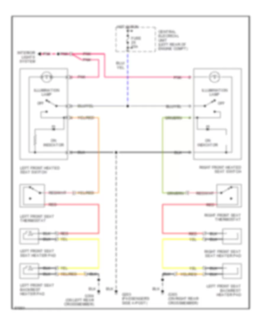 https://portal-diagnostov.com/license.html
Automotive Electricians Portal FZCO
Automotive Electricians Portal FZCO
https://portal-diagnostov.com/license.html
https://portal-diagnostov.com/license.html
Automotive Electricians Portal FZCO
Automotive Electricians Portal FZCOList of elements for Front Seat Heater Wiring Diagram for Volvo 850 1995:
- Central elecrical unit (left rear of engine compt)
- Fuse 25a
- G203 (passenger's side a-post)
- G303 (on right rear crossmember)
- G304 (on left rear crossmember)
- Hot in run
- Illumination lamp
- Interior lights system
- Left front heated seat switch
- Left front seat thermostat
- Left front seat backrest heater pad
- Left front seat seat heater pad
- Off
- On indicator
- Pnk
- Red
- Right front heated seat switch
- Right front seat seat heater pad
- Right front seat thermostat
Rear Seat Heater Wiring Diagram for Volvo 850 1995
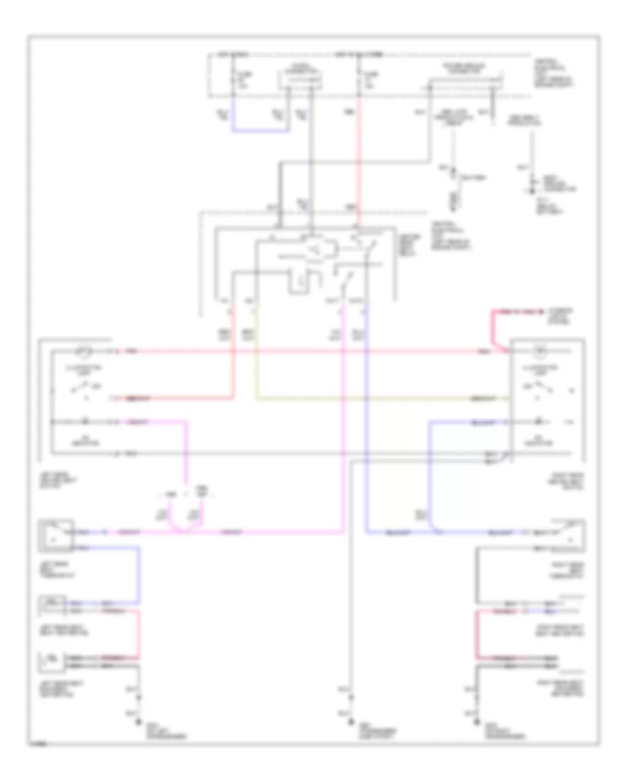 https://portal-diagnostov.com/license.html
Automotive Electricians Portal FZCO
Automotive Electricians Portal FZCO
https://portal-diagnostov.com/license.html
https://portal-diagnostov.com/license.html
Automotive Electricians Portal FZCO
Automotive Electricians Portal FZCOList of elements for Rear Seat Heater Wiring Diagram for Volvo 850 1995:
- 15i
- 15i-rail connector
- 1995 early production
- 1995 late production & 1996-97
- 1996,
- Battery
- Body ground connector
- Central electrical unit (left rear of engine compt)
- Fuse 10a
- Fuse 15a
- G111 (below battery)
- G303 (on right crossmember)
- G304 (on left crossmember)
- G901 (passenger's side a-post)
- Heated rear seat relay
- Hot at all times
- Hot in run
- Illumination lamp
- In1
- In2
- Interior lights system
- Left rear heated seat switch
- Left rear seat backrest heater pad
- Left rear seat seat heater pad
- Left rear seat thermostat
- Off
- On indicator
- Out1
- Out2
- Pnk
- Power ground connector
- Red
- Right rear heated seat switch
- Right rear seat backrest heater pad
- Right rear seat seat heater pad
- Right rear seat thermostat
POWER TOP/SUNROOF
Power Top/Sunroof Wiring Diagrams for Volvo 850 1995
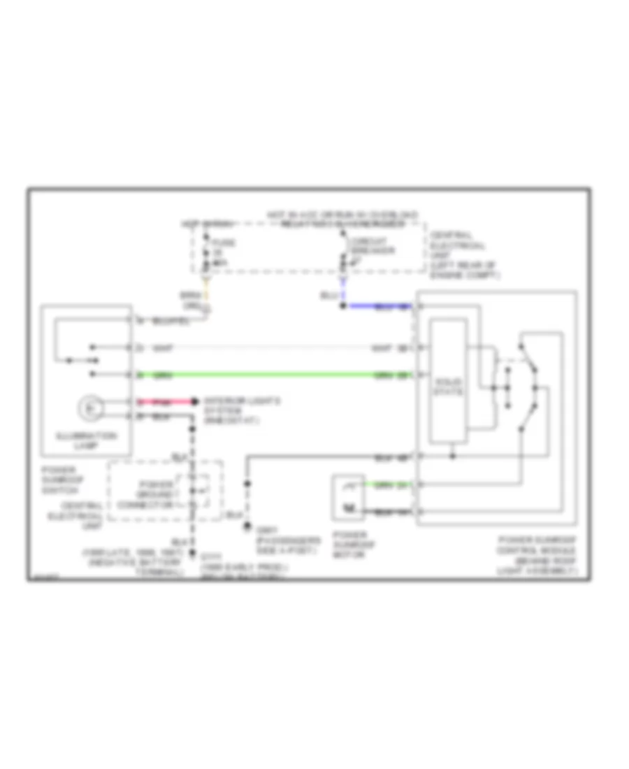 https://portal-diagnostov.com/license.html
Automotive Electricians Portal FZCO
Automotive Electricians Portal FZCO
https://portal-diagnostov.com/license.html
https://portal-diagnostov.com/license.html
Automotive Electricians Portal FZCO
Automotive Electricians Portal FZCOList of elements for Power Top/Sunroof Wiring Diagrams for Volvo 850 1995:
- Central electrical unit
- Central electrical unit (left rear of engine compt)
- Circuit breaker
- Fuse 10a
- G111 (1995 early prod.) (below battery)
- G901 (passenger's side a-post)
- Hot in acc or run w/ overload relay no.3 (x+) energized
- Hot in run
- Illumination lamp
- Interior lights system (rheostat)
- Pnk
- Power ground connector
- Power sunroof control module (behind roof light assembly)
- Power sunroof motor
- Power sunroof switch
- Solid state
POWER WINDOWS
Power Window Wiring Diagram for Volvo 850 1995
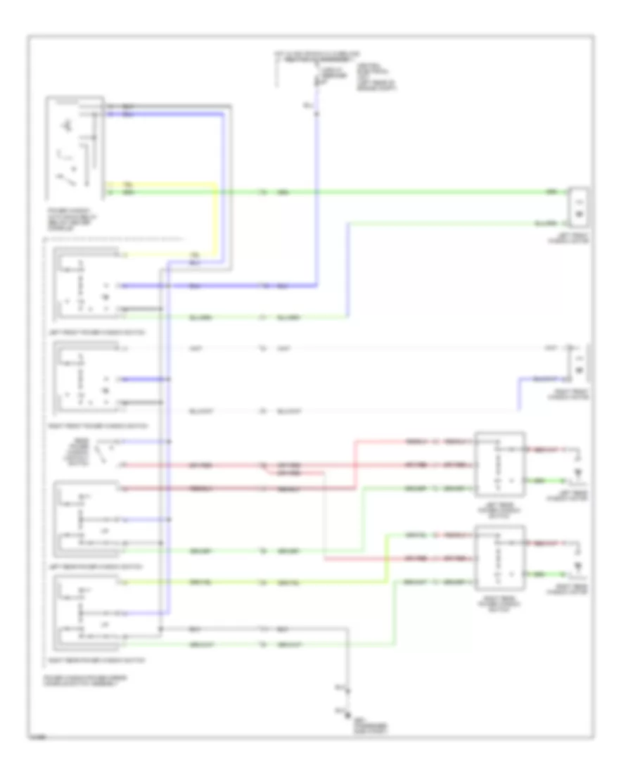 https://portal-diagnostov.com/license.html
Automotive Electricians Portal FZCO
Automotive Electricians Portal FZCO
https://portal-diagnostov.com/license.html
https://portal-diagnostov.com/license.html
Automotive Electricians Portal FZCO
Automotive Electricians Portal FZCOList of elements for Power Window Wiring Diagram for Volvo 850 1995:
- Central electrical unit (left rear of engine compt)
- Circuit breaker
- G901 (passenger side a-post)
- Hot in acc or run w/ overload relay #3 (x+) energized
- Left front power window switch
- Left front window motor
- Left rear power window switch
- Left rear window motor
- Power window auto down relay (below center console)
- Power window/power mirror console switch assembly
- Rear power window lock-out switch
- Right front power window switch
- Right front window motor
- Right rear power window switch
- Right rear window motor
RADIO
Radio Wiring Diagrams, with Amplifier for Volvo 850 1995
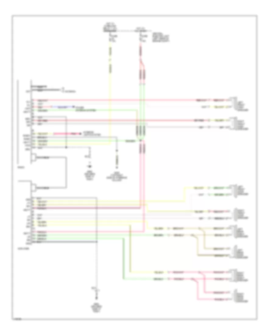 https://portal-diagnostov.com/license.html
Automotive Electricians Portal FZCO
Automotive Electricians Portal FZCO
https://portal-diagnostov.com/license.html
https://portal-diagnostov.com/license.html
Automotive Electricians Portal FZCO
Automotive Electricians Portal FZCOList of elements for Radio Wiring Diagrams, with Amplifier for Volvo 850 1995:
- +acc
- +ant
- +batt
- Amplifier
- Ant
- Antenna
- Central electric unit (left rear of engine compt)
- Din cable
- Dl+
- Dl-
- Dr+
- Dr-
- Fuse 10a
- Fuse 15a
- G205 (top right side of steering column)
- G900 (driver's side "a" post)
- Gnd
- Hot at all times
- Hot w/ overload relay 1 (x+) energized
- Interior lights system
- Left front dash speaker
- Left front door speaker
- Left rear door speaker
- Left rear shelf speaker
- Lf+
- Lf-
- Lr+
- Lr-
- Nca
- Pnk
- Power antenna system
- Radio
- Red
- Rf+
- Rf-
- Rheo+
- Rheo-
- Right front dash speaker
- Right front door speaker
- Right rear door speaker
- Right rear shelf speaker
- Rr+
- Rr-
Radio Wiring Diagrams, without Amplifier for Volvo 850 1995
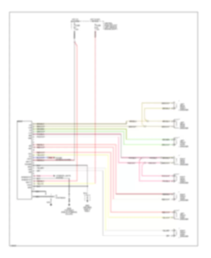 https://portal-diagnostov.com/license.html
Automotive Electricians Portal FZCO
Automotive Electricians Portal FZCO
https://portal-diagnostov.com/license.html
https://portal-diagnostov.com/license.html
Automotive Electricians Portal FZCO
Automotive Electricians Portal FZCOList of elements for Radio Wiring Diagrams, without Amplifier for Volvo 850 1995:
- +acc
- +ant
- +batt
- +dl
- +dr
- +lf
- +lr
- +rf
- +rheostat
- +rr
- -dl
- -dr
- -lf
- -lr
- -rf
- -rheostat
- -rr
- Antenna
- Central electric unit (left rear of engine compt)
- Dimmer
- Fuse 10a
- Fuse 15a
- G205 (top right side of steering column)
- G900 (driver's side "a" post)
- Gnd
- Hot at all times
- Hot in acc or run
- Interior lights system
- Left front dash speaker
- Left front door speaker
- Left rear door speaker
- Left rear shelf speaker
- Nca
- Pnk
- Power antenna system
- Radio
- Red
- Right front dash speaker
- Right front door speaker
- Right rear door speaker
- Right rear shelf speaker
SHIFT INTERLOCKS
Shift Interlock Wiring Diagram for Volvo 850 1995
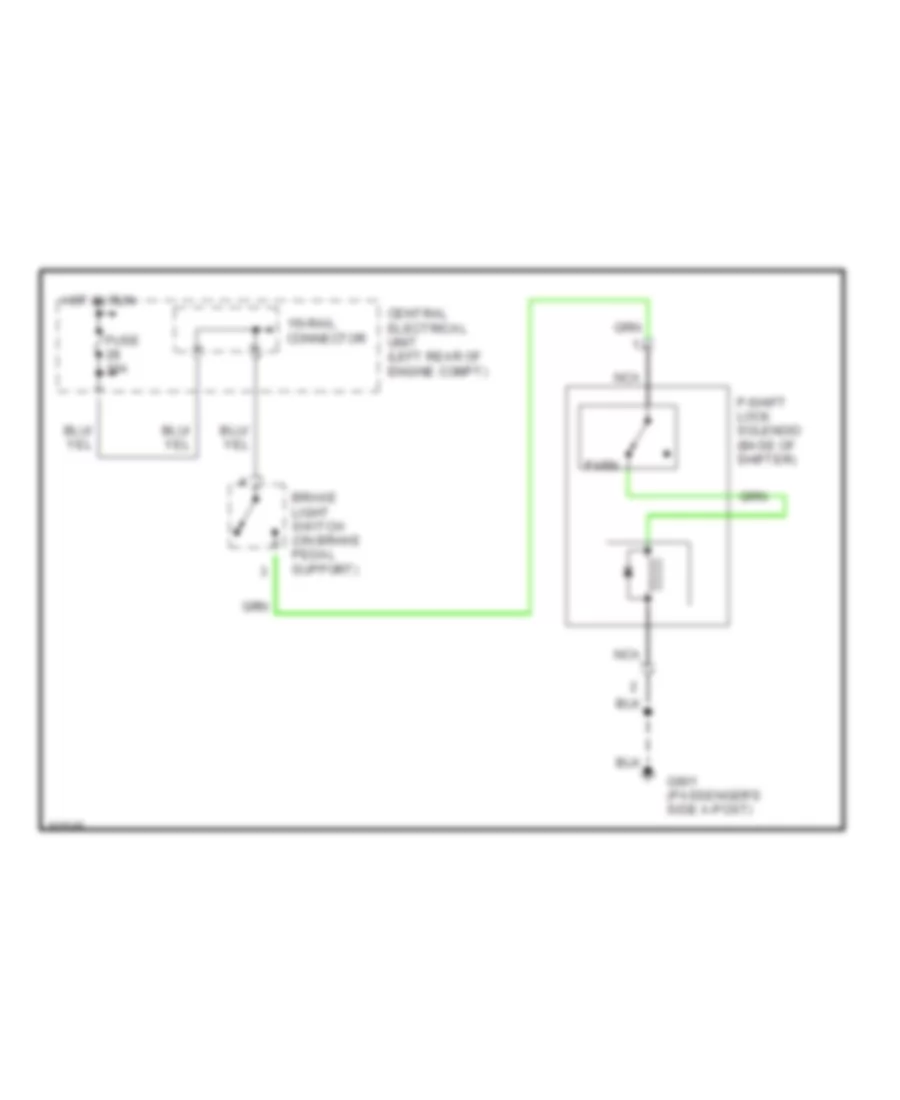 https://portal-diagnostov.com/license.html
Automotive Electricians Portal FZCO
Automotive Electricians Portal FZCO
https://portal-diagnostov.com/license.html
https://portal-diagnostov.com/license.html
Automotive Electricians Portal FZCO
Automotive Electricians Portal FZCOList of elements for Shift Interlock Wiring Diagram for Volvo 850 1995:
- 15i-rail connector
- Brake light switch (on brake pedal support)
- Central electrical unit (left rear of engine compt)
- Fuse 10a
- G901 (passenger's side a-post)
- Hot in run
- Nca
- P-shift lock solenoid (base of shifter)
- Park
STARTING/CHARGING
Charging Wiring Diagram for Volvo 850 1995
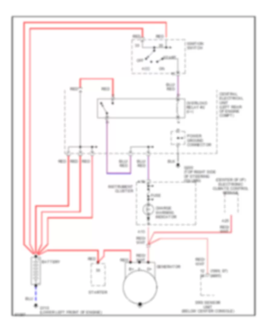 https://portal-diagnostov.com/license.html
Automotive Electricians Portal FZCO
Automotive Electricians Portal FZCO
https://portal-diagnostov.com/license.html
https://portal-diagnostov.com/license.html
Automotive Electricians Portal FZCO
Automotive Electricians Portal FZCOList of elements for Charging Wiring Diagram for Volvo 850 1995:
- (1996, 97) (1995)
- (center of i/p) electronic climate control module
- A13
- A18
- A25
- Acc
- Battery
- Central electrical unit (left rear of engine compt)
- Charge warning indicator
- Fuse
- G110 (lower left front of engine)
- G205 (top right side of steering column)
- Generator
- Ignition switch
- Instrument cluster
- Off
- Overload relay #2 (x+)
- Power ground connector
- Red
- Srs sensor unit (below center console)
- Start
- Starter
Starting Wiring Diagram for Volvo 850 1995
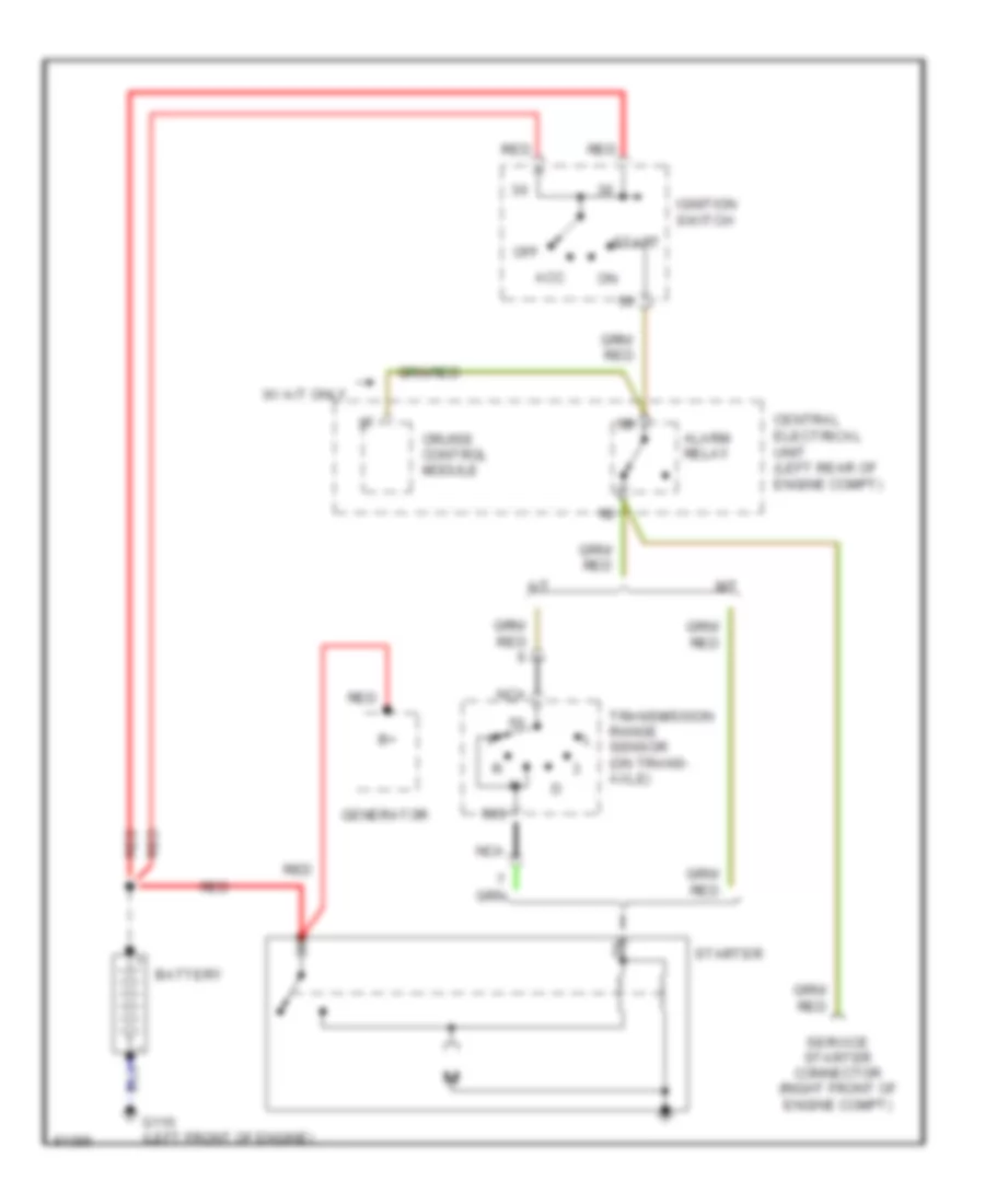 https://portal-diagnostov.com/license.html
Automotive Electricians Portal FZCO
Automotive Electricians Portal FZCO
https://portal-diagnostov.com/license.html
https://portal-diagnostov.com/license.html
Automotive Electricians Portal FZCO
Automotive Electricians Portal FZCOList of elements for Starting Wiring Diagram for Volvo 850 1995:
- 50s
- A/t
- Acc
- Alarm relay
- Battery
- Central electrical unit (left rear of engine compt)
- Cruise control module
- G110 (left front of engine)
- Generator
- Ignition switch
- M/t
- Nca
- Off
- Red
- Service starter connector (right front of engine compt)
- Start
- Starter
- Transmission range sensor (on trans- axle)
- W/ a/t only
SUPPLEMENTAL RESTRAINTS
Supplemental Restraint Wiring Diagram for Volvo 850 1995
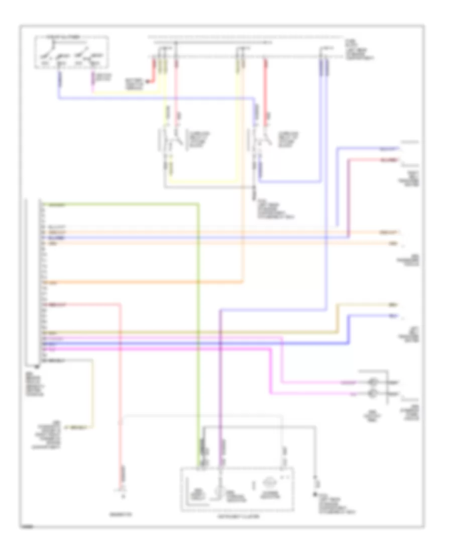 https://portal-diagnostov.com/license.html
Automotive Electricians Portal FZCO
Automotive Electricians Portal FZCO
https://portal-diagnostov.com/license.html
https://portal-diagnostov.com/license.html
Automotive Electricians Portal FZCO
Automotive Electricians Portal FZCOList of elements for Supplemental Restraint Wiring Diagram for Volvo 850 1995:
- (left rear of engine compartment)
- A13
- A17
- A18
- Acc
- Battery positive terminal
- Charge indicator
- Fuse block
- G104 (left rear of engine compartment, in fuse/relay box)
- Generator
- Hot at all times
- Ignition switch
- Instrument cluster
- Left belt tensioner igniter
- Nca
- Obd diagnostic socket b (right front corner of engine compartment)
- Off
- Overload relay 15+ (in fuse block)
- Overload relay x+ (in fuse block)
- Red
- Right belt tensioner igniter
- Run
- Srs contact reel
- Srs passenger module
- Srs safety circuit
- Srs sensor module (beneath center console)
- Srs steering wheel module
- Srs warning indicator
- Start
TRANSMISSION
Transmission Wiring Diagram for Volvo 850 1995
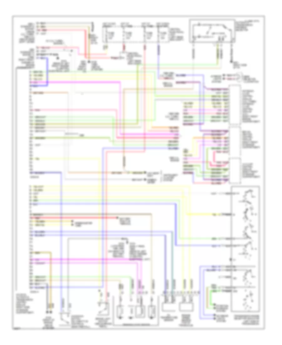 https://portal-diagnostov.com/license.html
Automotive Electricians Portal FZCO
Automotive Electricians Portal FZCO
https://portal-diagnostov.com/license.html
https://portal-diagnostov.com/license.html
Automotive Electricians Portal FZCO
Automotive Electricians Portal FZCOList of elements for Transmission Wiring Diagram for Volvo 850 1995:
- (rear of left front fender, in central electrical unit)
- (w/ 2.3l turbo engine)
- 15i
- 1995 2.4l engine
- 1995 vftc c
- 1995/1996 2.3l turbo, 1996 2.4l
- 50s
- A12
- A30
- Automatic transmission program selector
- Aw 50-42 automatic transmission control module (right side of engine compartment)
- B12
- B20
- B24
- B26
- B36
- B42
- Battery positive terminal
- Brake light switch (above brake pedal)
- Central electrical unit (left rear eng compt)
- Conn a
- Conn b
- Engine speed sensor (top of transaxle)
- Exterior lights system
- Ezk (di) ignition control module (right front of engine compartment)
- Fuse 11-1 15a
- Fuse 11-12 10a
- Fuse 11-15 10a
- Fuse 11-33 15a
- G104
- G104 (early prod 1995) (rear of left front fender in central electrical unit)
- G125 (1995) (above starter)
- G125 (front of engine, above starter)
- G201 (1996) (right side of i/p)
- G201 (right side of i/p)
- Gear selector illumination
- Hot at all times
- Hot in acc or run
- Hot in run or start
- Instrument cluster system
- Interior lights system
- Kickdown switch (on throttle controls, near firewall)
- Lh 3.2 mfi control module (right front of engine compartment)
- Low gear indic
- Motronic 4.3 mfi control module (2.3l turbo) motronic 4.4 mfi control module (2.4l) (right front engine compartment)
- Ms1
- Ms2
- Nca
- Obd diagnostic socket a (1995) (right front corner of engine compartment)
- Obd ii diagnostic
- Oil temperature sensor
- Pnk
- Red
- Socket (1995/96 2.3l turbo, 1996 2.4l) (above gear shift lever)
- Speedo- meter
- Speedometer (1996)
- Starting/ charging system
- Sth
- Sthg
- Transaxle solenoids
- Transmission range selector indicator (left side of transmission)
WARNING SYSTEMS
Warning System Wiring Diagrams for Volvo 850 1995
 https://portal-diagnostov.com/license.html
Automotive Electricians Portal FZCO
Automotive Electricians Portal FZCO
https://portal-diagnostov.com/license.html
https://portal-diagnostov.com/license.html
Automotive Electricians Portal FZCO
Automotive Electricians Portal FZCOList of elements for Warning System Wiring Diagrams for Volvo 850 1995:
- 15i
- 15i-rail connector
- 30-rail connector
- 31d
- Battery
- Central electrical unit
- Central electrical unit (left rear of engine compt)
- Fuse 15 10a
- Fuse 17 10a
- Fuse 28 10a
- G314 (on left rear crossmember)
- G900 (driver's side "a" pillar)
- Hot at all times
- Hot in run
- Ignition switch
- Interior lights system
- Key in
- Key-in ignition switch
- Left front door lock
- Left seat belt switch (in seat belt buckle)
- Nca
- Overhead console
- Red
- Seat belt indicator
- Seatbelt reminder/ key warning relay
- Signal ground connector
WIPER/WASHER
Front Wiper/Washer Wiring Diagram, Early Production for Volvo 850 1995
 https://portal-diagnostov.com/license.html
Automotive Electricians Portal FZCO
Automotive Electricians Portal FZCO
https://portal-diagnostov.com/license.html
https://portal-diagnostov.com/license.html
Automotive Electricians Portal FZCO
Automotive Electricians Portal FZCOList of elements for Front Wiper/Washer Wiring Diagram, Early Production for Volvo 850 1995:
- (below battery)
- 31b
- 53a
- 53b
- Body ground connector
- Central electrical unit (left rear of engine compt)
- Front washer motor
- Fuse 25a
- G111
- Headlamp wiper/washer circuit
- Headlamp wiper/washer circuit & horns system
- Hot in acc or on
- Int
- Off
- Power ground connector
- Signal ground connector
- Solid state
- Washer switch
- Windshield wiper intermittent relay
- Windshield wiper motor
- Windshield wiper/washer switch
- Wiper switch
Front Wiper/Washer Wiring Diagram, Late Production for Volvo 850 1995
 https://portal-diagnostov.com/license.html
Automotive Electricians Portal FZCO
Automotive Electricians Portal FZCO
https://portal-diagnostov.com/license.html
https://portal-diagnostov.com/license.html
Automotive Electricians Portal FZCO
Automotive Electricians Portal FZCOList of elements for Front Wiper/Washer Wiring Diagram, Late Production for Volvo 850 1995:
- 31b
- 53a
- 53b
- Battery
- Central electrical unit (left rear of engine compt)
- Front washer motor
- Fuse 25a
- Headlamp wiper/washer circuit
- Headlamp wiper/washer circuit & horns system
- Hot in acc or on
- Int
- Off
- Power ground connector
- Signal ground connector
- Solid state
- Washer switch
- Windshield wiper intermittent relay
- Windshield wiper motor
- Windshield wiper/washer switch
- Wiper switch
Headlamp Wiper/Washer Wiring Diagram, Early Production for Volvo 850 1995
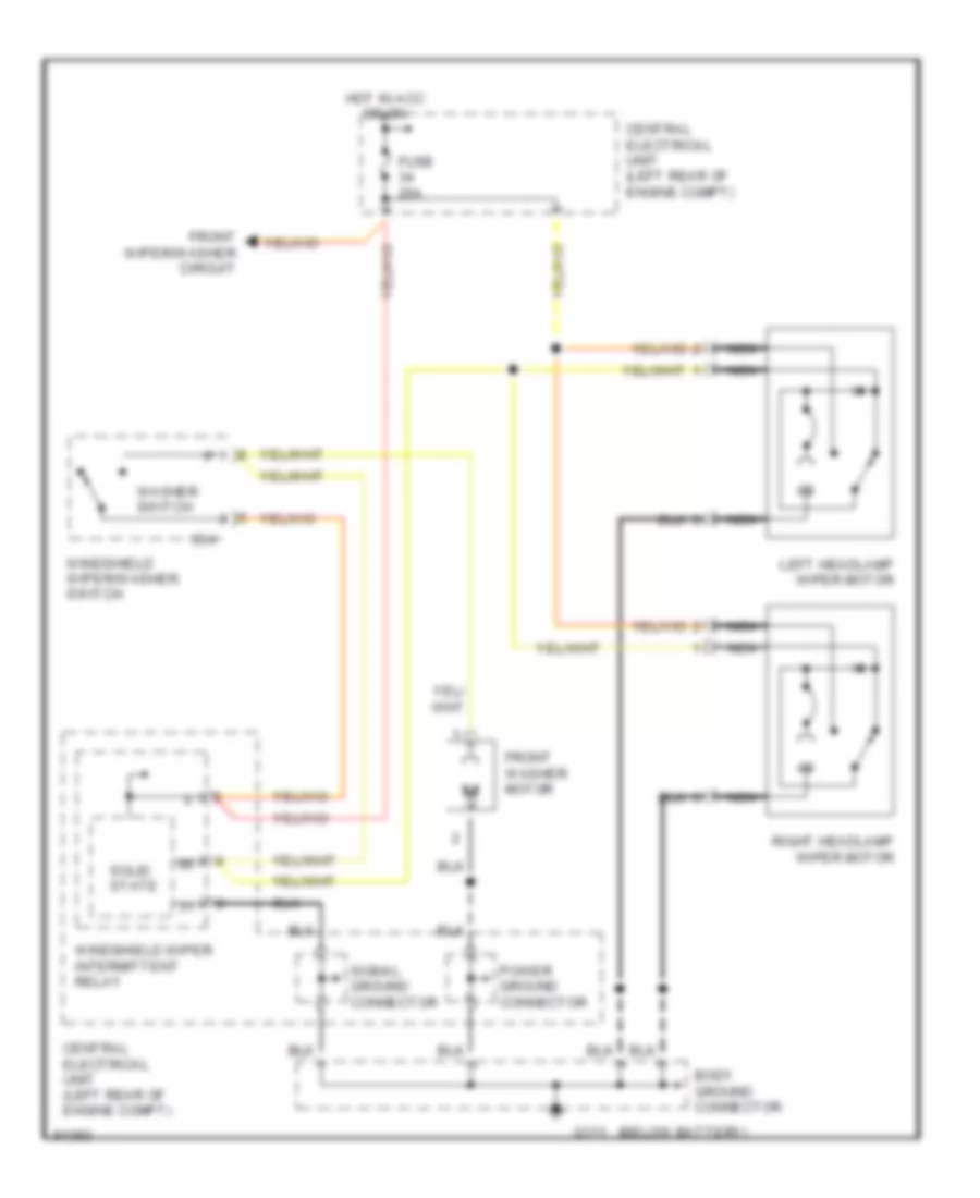 https://portal-diagnostov.com/license.html
Automotive Electricians Portal FZCO
Automotive Electricians Portal FZCO
https://portal-diagnostov.com/license.html
https://portal-diagnostov.com/license.html
Automotive Electricians Portal FZCO
Automotive Electricians Portal FZCOList of elements for Headlamp Wiper/Washer Wiring Diagram, Early Production for Volvo 850 1995:
- (below battery)
- 53a
- Body ground connector
- Central electrical unit (left rear of engine compt)
- Front washer motor
- Front wiper/washer circuit
- Fuse 25a
- G111
- Hot in acc or on
- Left headlamp wiper motor
- Nca
- Power ground connector
- Right headlamp wiper motor
- Signal ground connector
- Solid state
- Washer switch
- Windshield wiper intermittent relay
- Windshield wiper/washer switch
Headlamp Wiper/Washer Wiring Diagram, Late Production for Volvo 850 1995
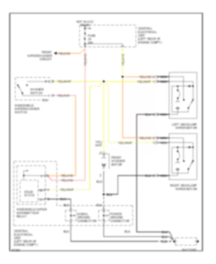 https://portal-diagnostov.com/license.html
Automotive Electricians Portal FZCO
Automotive Electricians Portal FZCO
https://portal-diagnostov.com/license.html
https://portal-diagnostov.com/license.html
Automotive Electricians Portal FZCO
Automotive Electricians Portal FZCOList of elements for Headlamp Wiper/Washer Wiring Diagram, Late Production for Volvo 850 1995:
- 53a
- Battery
- Central electrical unit (left rear of engine compt)
- Front washer motor
- Front wiper/washer circuit
- Fuse 25a
- Hot in acc or on
- Left headlamp wiper motor
- Nca
- Power ground connector
- Right headlamp wiper motor
- Signal ground connector
- Solid state
- Washer switch
- Windshield wiper intermittent relay
- Windshield wiper/washer switch
Rear Wiper/Washer Wiring Diagram, Early Production for Volvo 850 1995
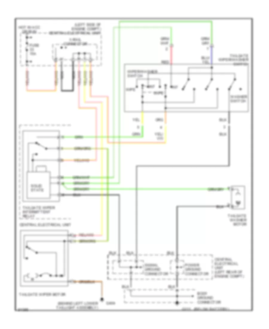 https://portal-diagnostov.com/license.html
Automotive Electricians Portal FZCO
Automotive Electricians Portal FZCO
https://portal-diagnostov.com/license.html
https://portal-diagnostov.com/license.html
Automotive Electricians Portal FZCO
Automotive Electricians Portal FZCOList of elements for Rear Wiper/Washer Wiring Diagram, Early Production for Volvo 850 1995:
- (behind left lower taillight assembly)
- (below battery)
- (left side of engine compt) central electrical unit
- Body ground connector
- Central electrical unit
- Central electrical unit (left rear of engine compt)
- Fuse 15a
- G111
- G404
- Hot in acc or run
- Int
- Nca
- Power ground connector
- Red
- Signal ground connector
- Solid state
- Tailgate washer motor
- Tailgate wiper intermittent relay
- Tailgate wiper motor
- Tailgate wiper/washer switch
- Washer switch
- Wipe
- Wiper/washer switch
- X-rail connector
Rear Wiper/Washer Wiring Diagram, Late Production for Volvo 850 1995
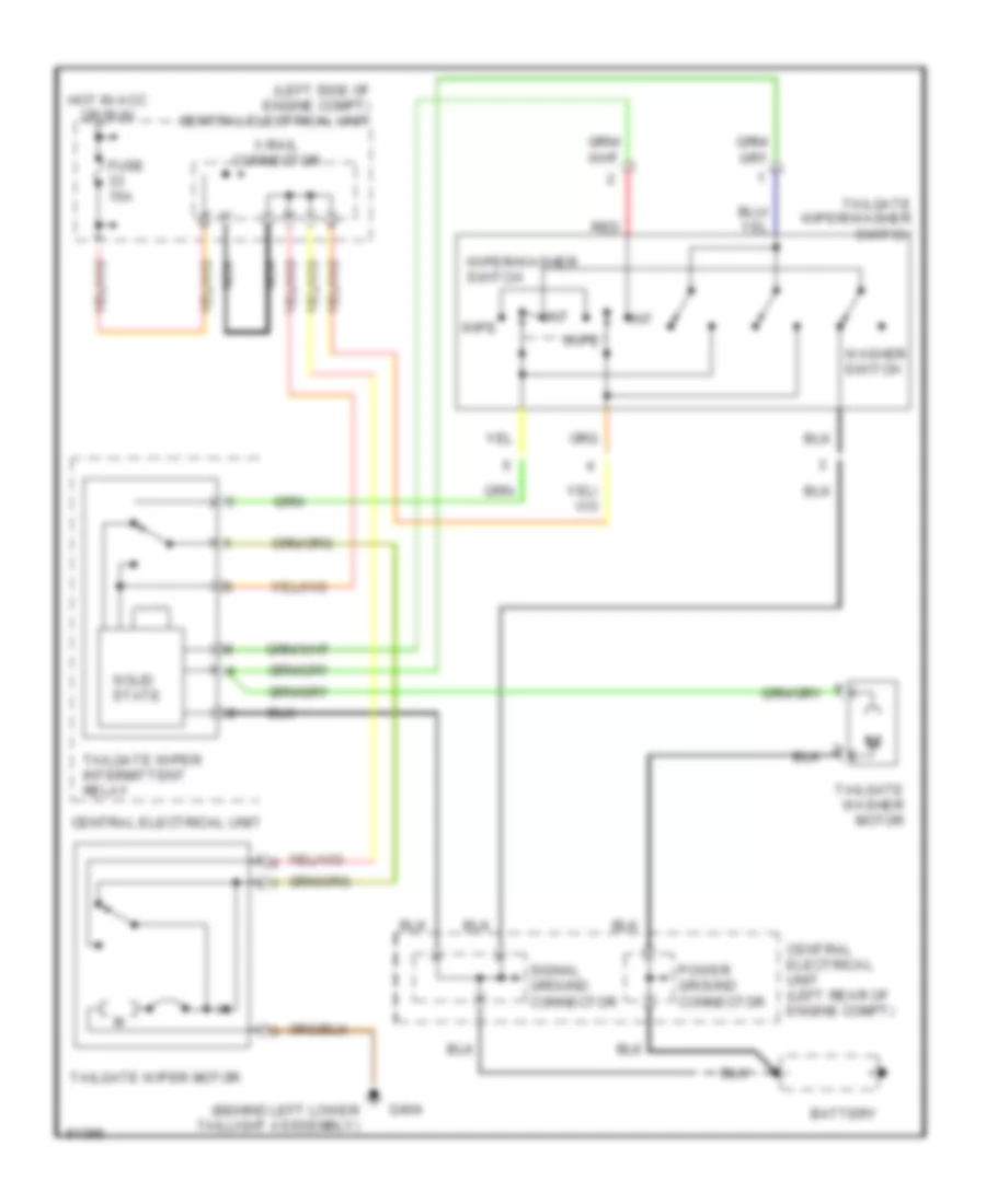 https://portal-diagnostov.com/license.html
Automotive Electricians Portal FZCO
Automotive Electricians Portal FZCO
https://portal-diagnostov.com/license.html
https://portal-diagnostov.com/license.html
Automotive Electricians Portal FZCO
Automotive Electricians Portal FZCOList of elements for Rear Wiper/Washer Wiring Diagram, Late Production for Volvo 850 1995:
- (behind left lower taillight asssembly)
- (left side of engine compt) central electrical unit
- Battery
- Central electrical unit
- Central electrical unit (left rear of engine compt)
- Fuse 15a
- G404
- Hot in acc or run
- Int
- Nca
- Power ground connector
- Red
- Signal ground connector
- Solid state
- Tailgate washer motor
- Tailgate wiper intermittent relay
- Tailgate wiper motor
- Tailgate wiper/washer switch
- Washer switch
- Wipe
- Wiper/washer switch
- X-rail connector

 Čeština
 Dansk
Dansk Deutsch
 Ελληνικά
 English
 English
 Español
 Suomi
Suomi Français
 Français
 עברית
עברית Hrvatski
 Magyar
 Italiano
 日本語
日本語 Nederlands
 Polski
 Português
 Português
 Română
 Русский
 Slovenčina
 Slovenščina
 Svenska
 Türkçe
 中文 (中国)
