AIR CONDITIONING
Air Conditioning Wiring Diagrams for Isuzu Trooper LS 1998
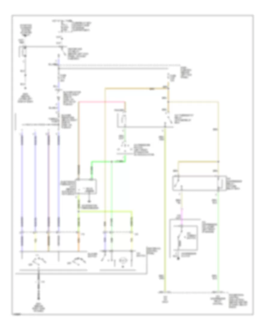
List of elements for Air Conditioning Wiring Diagrams for Isuzu Trooper LS 1998:
- A/c compressor (on lower left front of engine)
- A/c compressor relay (in fuse/ relay box)
- A/c compressor relay control
- A/c on input
- A/c pressure switch (left front of radiator, on accumulator)
- A/c switch
- A/c thermo switch
- A/c thermostat relay (in fuse/relay box)
- B14
- Blower motor (below right side of dash, on bottom of plenum)
- Blower resistors (below right side of dash, on plenum)
- Blower switch
- C-1
- C-3
- Compressor clutch
- Dash fuse box (behind left kick panel)
- E15
- Electronic thermostat unit (behind glove box, on plenum)
- Evaporator thermosensor
- Fl-1 main 80a
- Fuse c-19 25a
- Fuse c-20 10a
- Fuse/relay box (on right side of engine compartment)
- G201 (behind right side of dash)
- G202 (behind lower left side of dash)
- Heater and a/c relay (behind left kick panel, on dash fuse box)
- Heater-a/c control panel
- Hot at all times
- I-18
- I-23
- Off
- Powertrain control module (pcm) (behind center of dash, below radio)
- Solid state
- Starting/ charging system (starter relay)
- Thermo fuse
 Čeština
 Dansk
Dansk Deutsch
 Ελληνικά
 English
 English
 Español
 Suomi
Suomi Français
 Français
 עברית
עברית Hrvatski
 Magyar
 Italiano
 日本語
日本語 한국어
한국어 Polski
 Português
 Português
 Română
 Русский
 Slovenčina
 Slovenščina
 Svenska
 Türkçe
 中文 (中国)
 Nederlands