ANTI-LOCK BRAKES
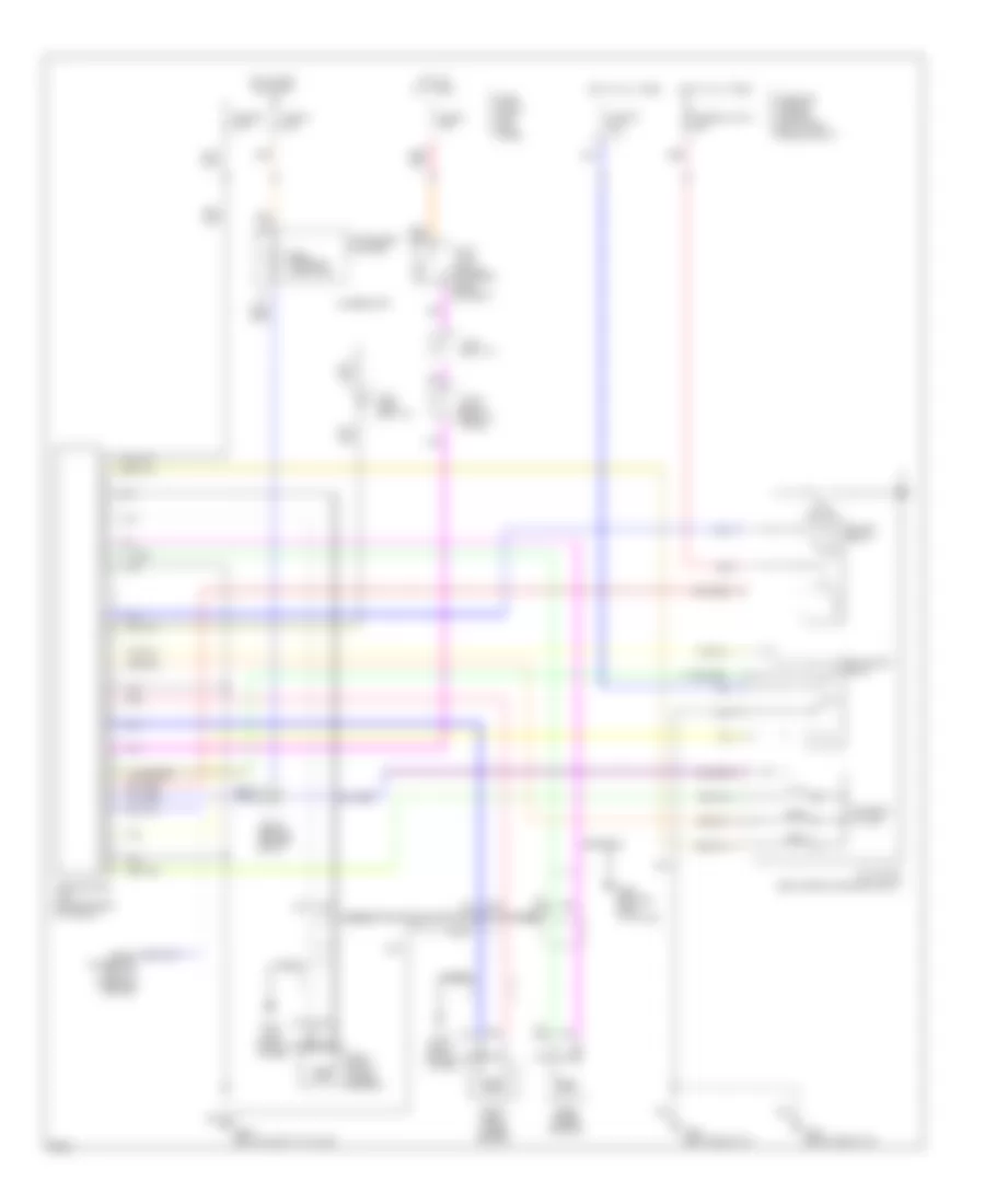
Anti-lock Brake Wiring Diagrams for Infiniti J30 t 1997
List of elements for Anti-lock Brake Wiring Diagrams for Infiniti J30 t 1997:
- (right rear of engine compt)
- (right shock tower)
- Abs control
- Abs warning indicator
- Actuator
- Actuator relay
- All times
- Alternator
- Fuse 20 7.5a
- Fuse 31 7.5a
- Fuse 4 15a
- Fuse 57 20a
- Fuse and fusible link box (right side engine compt)
- Fuse block (left kick panel)
- Fusible link c 30a
- G102 (left shock tower)
- G103
- G201 (right side of i/p)
- G202 (left side of i/p)
- G904 (bottom left "c" pillar)
- G905 (bottom right "c" pillar)
- Hot at
- Hot at all times
- Hot in run or start
- Instrument cluster
- J/c-10 (behind center of i/p)
- J/c-13 (right rear of trunk)
- J/c-6 (left i/p)
- J/c-7 (1995) (left i/p)
- Left front wheel sensor
- Motor
- Motor relay
- Nca
- Pnk
- Rear wheel sensor
- Red
- Right front wheel sensor
- Solenoid valves
- Stop lamp switch (on brake pedal support)
- Unit (center rear of trunk)
 Čeština
 Dansk
Dansk Deutsch
 Ελληνικά
 English
 English
 Español
 Suomi
Suomi Français
 Français
 עברית
עברית Hrvatski
 Magyar
 Italiano
 日本語
日本語 한국어
한국어 Polski
 Português
 Português
 Română
 Русский
 Slovenčina
 Slovenščina
 Svenska
 Türkçe
 中文 (中国)
 Nederlands