AIR CONDITIONING
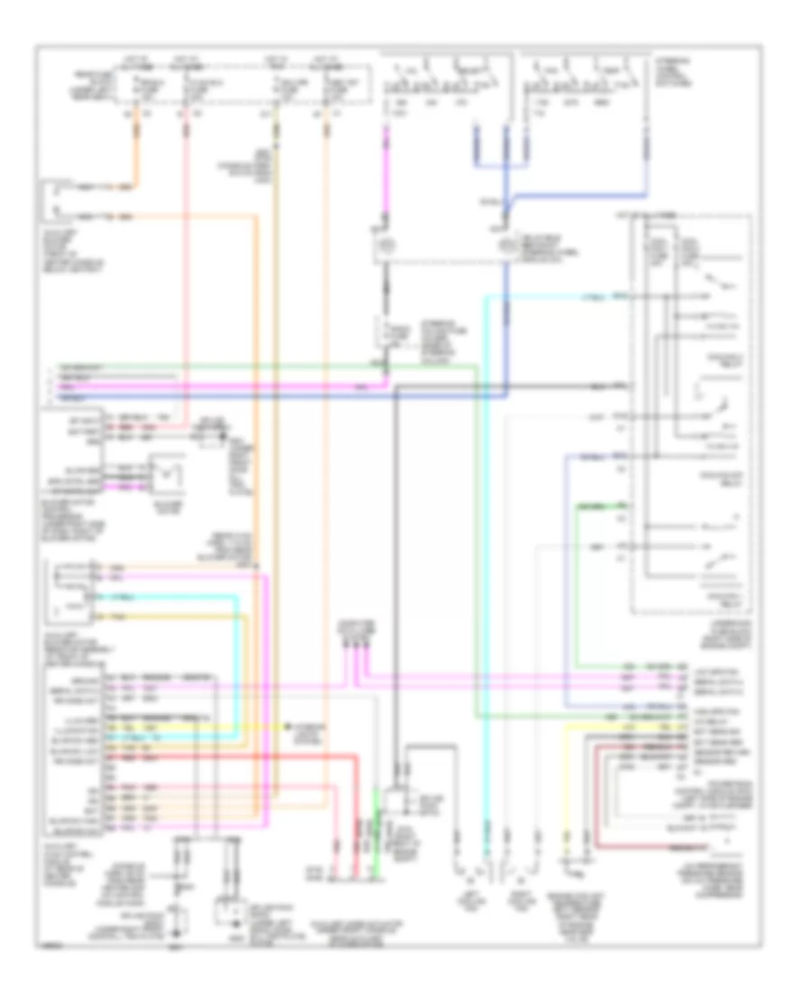
Automatic A/C Wiring Diagram (1 of 2) for Cadillac DeVille DTS 2003
 https://portal-diagnostov.com/license.html
Automotive Electricians Portal FZCO
Automotive Electricians Portal FZCO
https://portal-diagnostov.com/license.html
https://portal-diagnostov.com/license.html
Automotive Electricians Portal FZCO
Automotive Electricians Portal FZCO
List of elements for Automatic A/C Wiring Diagram (1 of 2) for Cadillac DeVille DTS 2003:
- inst panel
- (body harn, 53.5 cm from c201)
- (i/p harn, 65 cm from radio conn breakout)
- (left front corner of engine) g100
- A/c clu fuse 15a
- A/c compressor clutch
- A/c compressor clutch solenoid
- A/c compressor temperature switch
- A/c low temp
- A/c refrigerant low temperature sensor (rear of engine compt, on a/c low pressure line)
- A10
- A11
- A12
- Ac clu relay
- Acc
- Air inlet act drv
- Air inlet act sig
- Air mix act drv
- Air mix act sig
- Air temperature actuator assembly (on right side of of hvac module)
- Ambient air temperature sensor (on hood latch support)
- Aux
- Auxiliary air temperature sensor (under front console, near aux blower mtr)
- B10
- B11
- Bat
- Blwr spd cntrl
- C11
- Computer data lines system
- Dash integration module (dim) (behind right side of dash, near blower motor)
- Dim fuse 10a
- Drvr air mix drv
- Drvr air mix sig
- G201 (under right front door sill trim plate)
- Ground
- Headlights system
- Hot at all times
- Hot in on
- Hot in on or start
- Hvac fuse 10a
- Iat sens cntrl
- Iat sens sig
- Ign
- Ign sw fuse 15a
- Ignition switch
- Inside air temperature sensor (behind left side of dash, left of steering column)
- Instrument panel integration module (above radio)
- Left air temperature actuator (on left side of hvac module)
- Left sun load sensor
- Lh sun load sens
- Lock
- Lower left air temperature sensor (under left side of dash, in a/c dash)
- Lower right air temperature sensor (under right side of dash, in a/c duct)
- Mode act drv
- Mode act sig
- Mode actuator (on left side of hvac module)
- Nca
- Pnk
- Rear fuse block (under left rear seat)
- Recirculation actuator (under right side of dash, right of blower motor)
- Red
- Rh sun load sens
- Right
- Right sun load sensor
- Rr air mix act drv
- Rr air mix act sig
- S130
- S205
- S207 (i/p harn, 86.1 cm from
- S213 (body harn, 73.2 cm from c200)
- S215
- Sensor return
- Serial data 2
- Splice pack sp201
- Start
- Steer whl ctrl
- Sun load sensor assembly (at top center of dash, in defogger grille)
- Tan
- Temp sens input
- Underhood fuse block (right side of engine compt)
- Upper left air temperature sensor (under left side of dash, in a/c duct)
- Upper right air temperature sensor (under right side of dash, in a/c duct)
- Voltage sens
Automatic A/C Wiring Diagram (2 of 2) for Cadillac DeVille DTS 2003
List of elements for Automatic A/C Wiring Diagram (2 of 2) for Cadillac DeVille DTS 2003:
- (console harn, 68 cm from rear heater and a/c control module conn)
- (dhs)
- (dts)
- (rear hvac harn, 17.5 cm from rear blower motor) s307
- 350(dhs)
- 450(dts)
- A/c refrigerant pressure sensor (on a/c pressure hose, near compressor)
- A/c relay
- Auxiliary blower motor (front of center console, below ashtray)
- Auxiliary blower motor resistor assembly (at front of center console)
- Auxiliary hvac control module (at rear of center console)
- Auxiliary mode actuator (under front console, near auxiliary blower motor)
- B10
- Bat
- Battery
- Blower motor
- Blower motor control processor (under right side of dash, right of blower motor)
- Blwr grd
- Blwr sw high
- Blwr sw low
- Blwr sw m/h
- Blwr sw med
- Computer data lines system
- Cool fan 1 fuse 30a
- Cool fan 2 fuse 30a
- Coolfan 1 relay
- Coolfan 2 relay
- Coolfan s/p relay
- D10
- D11
- Dhs
- Dts
- E nca
- E10
- Ect sens grd
- Ect sens sig
- Engine coolant temperature (ect) sensor (right rear of engine, near egr valve)
- F11
- Fan
- G nca
- G104 (right front of engine compt)
- G201
- G201 (under right front door sill trim plate)
- Grd
- Ground
- High spd fan
- Hot at all times
- Hot in run
- Hvac blo fuse 40a
- Ign
- Ign 3 rr fuse 10a
- Illum grd
- Illumination
- Inflatable restraint steering wheel module coil
- Interior lights system
- Left cooling fan
- Low spd fan
- Mem t&t fuse 10a
- Nca
- Pnk
- Powertrain control module (pcm) (left side of engine compt, in air cleaner)
- Radio fuse 2a
- Rear fuse block (under left rear seat)
- Red
- Right cooling fan
- Rr blo fuse 10a
- Rr mode act
- S300
- S301 (dts) (console harn, 50.5 cm from c304)
- Select
- Sensor grd
- Sensor return
- Serial data 2
- Sp cntrl out
- Sp input
- Spd cntrl grd
- Splice pack sp104
- Splice pack sp200 (under left front door sill trim plate) g200 plate)
- Splice pack sp201
- Splice pack sp201 (under right front door sill trim plate)
- Steering column fuse holder (base of steering column)
- Steering wheel control switches
- Tan
- Temp
- Underhood fuse block (right side of engine compt)
- Vol
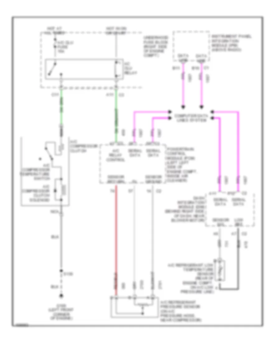
Compressor Wiring Diagram for Cadillac DeVille DTS 2003
List of elements for Compressor Wiring Diagram for Cadillac DeVille DTS 2003:
- A/c clu fuse 15a
- A/c compressor clutch
- A/c compressor clutch solenoid
- A/c compressor temperature switch
- A/c refrigerant low temperature sensor (rear of engine compt, on a/c low a
- A/c refrigerant pressure sensor (on a/c pressure hose, near compressor)
- A/c relay control
- A11
- A12
- Ac clu relay
- B11
- C1 b10
- Computer data lines system
- Dash integration module (dim) (behind right side of dash, near blower motor)
- Data line
- G100 (left front corner of engine)
- Hot at all times
- Hot in on or start
- Instrument panel integration module (ipm) (above radio)
- Low ref
- Nca
- Powertrain control module (pcm) (left left side of engine compt, inside air cleaner)
- Pressure line)
- S130
- Sensor ground
- Sensor return
- Sensor sig
- Serial data
- Underhood fuse block (right side of engine compt)

 Čeština
 Dansk
Dansk Deutsch
 Ελληνικά
 English
 English
 Español
 Suomi
Suomi Français
 Français
 עברית
עברית Hrvatski
 Magyar
 Italiano
 日本語
日本語 한국어
한국어 Polski
 Português
 Português
 Română
 Русский
 Slovenčina
 Slovenščina
 Svenska
 Türkçe
 中文 (中国)