TRANSMISSION
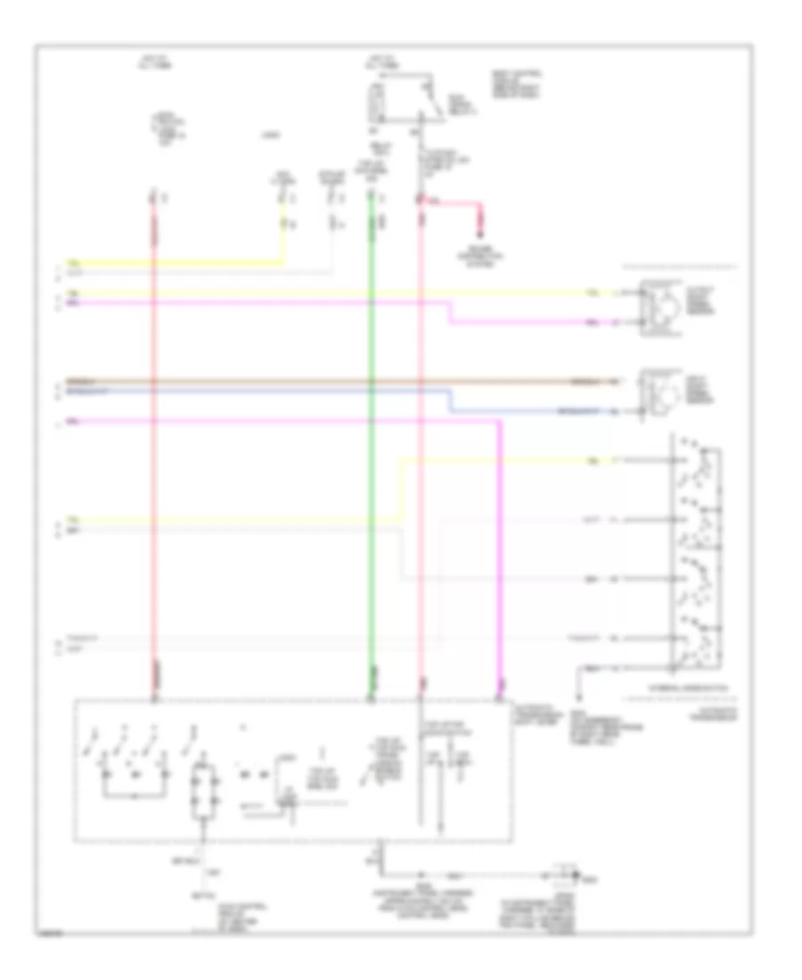
A/T Wiring Diagram (1 of 2) for Cadillac XLR V 2006
 https://portal-diagnostov.com/license.html
Automotive Electricians Portal FZCO
Automotive Electricians Portal FZCO
https://portal-diagnostov.com/license.html
https://portal-diagnostov.com/license.html
Automotive Electricians Portal FZCO
Automotive Electricians Portal FZCO
List of elements for A/T Wiring Diagram (1 of 2) for Cadillac XLR V 2006:
- 1-2 shft sol vlv
- 1-2 shift sol
- 2-3 shft sol vlv
- 2-3 shift sol
- 4-5 shft sol vlv
- 4-5 shift sol
- 4.4l
- 4.6l
- A/t iss hi sig
- A/t iss lo sig
- Acc voltage
- Acc/tcm fuse 3 10a
- Automatic transaxle fluid temperature sensor
- Automatic transmission
- B+ voltage
- Batt +
- Class 2 ser data
- Computer data lines system
- D11
- E11
- Ecm/tcm fuse 11 15a
- Engine control module (behind lower right front fender)
- G106
- Gear high trans temp service trans shift to prk
- Ground
- Head up display
- Hi spd can +
- Hi spd can -
- Hi spd ser data +
- Hi spd ser data -
- Hot at all times
- Hot in run or start
- Hud message center
- Ign 1 vlt
- Instrument panel cluster
- Logic
- Mesg req tcm
- Message center
- Oss hi sig
- Oss low sig
- Pc sol vlv hi cntl
- Pc sol vlv lo cntl
- Pnk
- Power distribution system
- Pressure control sol
- Sp106 (in engine harness, right rear of engine compt by battery, grounded to g106)
- Stop lamp sw sig
- Stop lp sw sig
- Tan
- Tap up/dwn gear
- Tap up/dwn sw sig
- Tcc pwm sol
- Tcc sol vlv cntl
- Tft sen lo ref
- Tft sens sig
- Transmission control module (behind lower right side of front fender)
- Trs a
- Trs b
- Trs c
- Trs p
- Underhood fuse block (right rear of engine compt)
- Up- shift ind cntl
- Up-shift
- Up-shift ind
A/T Wiring Diagram (2 of 2) for Cadillac XLR V 2006
List of elements for A/T Wiring Diagram (2 of 2) for Cadillac XLR V 2006:
- Acc vlt sig
- Automatic transmission
- Automatic transmission shift lever
- Body control module (behind right side of dash)
- Btsi sol/col lock fuse 19 10a
- G202
- G402 (on underbody, on right rear frame by right rear wheel well)
- Hot at all times
- Hvac control module (at center of dash)
- I/p lamp cntl
- Input shaft speed sensor
- Internal mode switch
- Logic
- Output shaft speed sensor
- Pnk
- Power distribution system
- Relay cntl
- Run/ crank relay 2
- S246 (instrument panel harness, approximately 35.0 cm from hvac control head) control head)
- Sp202 (in instrument panel harness, at base of right a pillar behind trim panel, grounded to g202)
- Stplmp sw sig
- Tap dwn -
- Tap up +
- Tap up/ dwn enbl sig
- Tap up/ tap dwn enbl sig
- Tap up/ tap dwn trans- mission enable switch
- Tap up/tap down switch
- Tutd sw/ strg col sw fuse 15 2a

 Čeština
 Dansk
Dansk Deutsch
 Ελληνικά
 English
 English
 Español
 Suomi
Suomi Français
 Français
 עברית
עברית Hrvatski
 Magyar
 Italiano
 日本語
日本語 한국어
한국어 Polski
 Português
 Português
 Română
 Русский
 Slovenčina
 Slovenščina
 Svenska
 Türkçe
 中文 (中国)