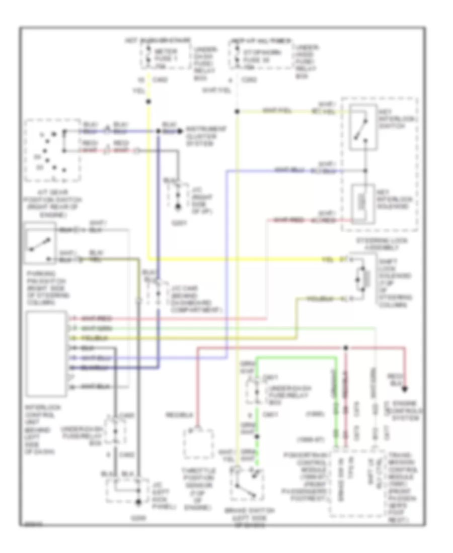
SHIFT INTERLOCKS
Shift Interlock Wiring Diagram for Honda Odyssey LX 1996
List of elements for Shift Interlock Wiring Diagram for Honda Odyssey LX 1996:
- (behind left side of dash)
- (top of engine)
- A/t gear position switch (right rear of
- A22
- B12
- Brake sw in
- Brake switch (left side of dash)
- C262
- C401
- C402
- C405
- C474
- C475
- C477
- C479
- D12 (1995)
- D5 (1996-97)
- Engine controls system
- Engine)
- G200
- G201
- Hot at all times
- Hot in on or start
- Instrument cluster system
- Interlock control unit
- J/c (left kick panel)
- J/c (right side of i/p)
- J/c c445 (behind dashboard compartment)
- Key interlock solenoid
- Key interlock switch
- Meter fuse 1 10a
- Parking pin switch (right side of steering column)
- Powertrain control module (1996-97) (front passenger's footrest)
- Rly ctrl
- Shft lk
- Shift lock solenoid (top of steering column)
- Steering lock assembly
- Stop/horn fuse 30 15a
- Throttle position sensor
- Tps in
- Trans- mission control module (1995) (front passen- ger's foot rest)
- Under- dash fuse/ relay box
- Under- hood fuse/ relay box
- Under-dash fuse/relay box
 Čeština
 Dansk
Dansk Deutsch
 Ελληνικά
 English
 English
 Español
 Suomi
Suomi Français
 Français
 עברית
עברית Hrvatski
 Magyar
 Italiano
 日本語
日本語 한국어
한국어 Polski
 Português
 Português
 Română
 Русский
 Slovenčina
 Slovenščina
 Svenska
 Türkçe
 中文 (中国)
 Nederlands